EP2377708A2 - Soft top for a convertible vehicle - Google Patents
Soft top for a convertible vehicle Download PDFInfo
- Publication number
- EP2377708A2 EP2377708A2 EP20110162108 EP11162108A EP2377708A2 EP 2377708 A2 EP2377708 A2 EP 2377708A2 EP 20110162108 EP20110162108 EP 20110162108 EP 11162108 A EP11162108 A EP 11162108A EP 2377708 A2 EP2377708 A2 EP 2377708A2
- Authority
- EP
- European Patent Office
- Prior art keywords
- soft
- unit
- component body
- components
- hood according
- Prior art date
- Legal status (The legal status is an assumption and is not a legal conclusion. Google has not performed a legal analysis and makes no representation as to the accuracy of the status listed.)
- Granted
Links
Images


Classifications
-
- B—PERFORMING OPERATIONS; TRANSPORTING
- B60—VEHICLES IN GENERAL
- B60J—WINDOWS, WINDSCREENS, NON-FIXED ROOFS, DOORS, OR SIMILAR DEVICES FOR VEHICLES; REMOVABLE EXTERNAL PROTECTIVE COVERINGS SPECIALLY ADAPTED FOR VEHICLES
- B60J7/00—Non-fixed roofs; Roofs with movable panels, e.g. rotary sunroofs
- B60J7/08—Non-fixed roofs; Roofs with movable panels, e.g. rotary sunroofs of non-sliding type, i.e. movable or removable roofs or panels, e.g. let-down tops or roofs capable of being easily detached or of assuming a collapsed or inoperative position
- B60J7/12—Non-fixed roofs; Roofs with movable panels, e.g. rotary sunroofs of non-sliding type, i.e. movable or removable roofs or panels, e.g. let-down tops or roofs capable of being easily detached or of assuming a collapsed or inoperative position foldable; Tensioning mechanisms therefor, e.g. struts
- B60J7/1226—Soft tops for convertible vehicles
- B60J7/1265—Soft tops for convertible vehicles characterised by kinematic movements, e.g. using parallelogram linkages
-
- B—PERFORMING OPERATIONS; TRANSPORTING
- B60—VEHICLES IN GENERAL
- B60J—WINDOWS, WINDSCREENS, NON-FIXED ROOFS, DOORS, OR SIMILAR DEVICES FOR VEHICLES; REMOVABLE EXTERNAL PROTECTIVE COVERINGS SPECIALLY ADAPTED FOR VEHICLES
- B60J7/00—Non-fixed roofs; Roofs with movable panels, e.g. rotary sunroofs
- B60J7/08—Non-fixed roofs; Roofs with movable panels, e.g. rotary sunroofs of non-sliding type, i.e. movable or removable roofs or panels, e.g. let-down tops or roofs capable of being easily detached or of assuming a collapsed or inoperative position
- B60J7/12—Non-fixed roofs; Roofs with movable panels, e.g. rotary sunroofs of non-sliding type, i.e. movable or removable roofs or panels, e.g. let-down tops or roofs capable of being easily detached or of assuming a collapsed or inoperative position foldable; Tensioning mechanisms therefor, e.g. struts
- B60J7/1226—Soft tops for convertible vehicles
Definitions
- the invention relates to a soft-top hood for a convertible vehicle according to the closer defined in the preamble of claim 1.
- Soft-top tops for convertible vehicles with various top mechanisms are known from practice, by means of which they can be transferred between a closed state and an open state.
- Conventional soft-top covers are often transferred by means of a Z-shaped folding from the closed state to the open state, wherein a rear window is moved in the opposite direction to the main columns and forms the lowest component when the top is off.
- a rigid, a flat dome-like module forming movement unit consisting of rear window, clamp, Eckspriegel and main pillars, which is displaced by means of a four-bar link between a position with the roof closed and a contrast pivoted rearward down position with the top down.
- the rear portion of the hood can be similar to that of a hard-top hood.
- a hood Due to the rigid movement unit such a hood has the disadvantage that the individual components of the movement unit can not be moved to each other at a top opening and the top can therefore only be used when there is enough space for the top including the movement unit in a rear-side storage compartment.
- the main pillars and a wheel arch of the convertible vehicle it can come to bottlenecks at a top opening.
- the invention provides a soft-top convertible top for a convertible vehicle, which can be moved between a closed position covering a passenger compartment and an open position releasing the passenger compartment, having a component body, which is at least partially covered by a flexible top cloth, which serves as components a rear window, a Stoffhaltebügel, a Eckspriegel and main columns, wherein the orientation of the components of the component body to each other in a transfer of the top between the closed position and the open position remains.
- a unit consisting of at least one component of the component body is movable in a transition of the top between the closed position and the open position relative to the other components of the component body within movement limits, which are predetermined by the top cloth.
- the component body according to the invention is limited in particular by curved, as simple as possible planes, which are spanned by the rear window, the fabric support bracket and the Eckspriegel. Furthermore, the component body is delimited by a plane in which the two main pillars are located.
- the component body thus represents a to a certain extent rigid module, which can be "compressed” by a limited mobility of the components to each other.
- An inventively designed soft top canopy has the advantage that the component group can be transferred as a dome-like structure in a rear-side storage space and this can be stored adapted to the space requirements due to their flexibility.
- the component body is preferably reducible with the top down, wherein a change in the shape of the component body can be realized by a movable mounting of at least one unit of the components in relation to the other components.
- a fabric length of the top cloth u. a. be formed very short in the main columns, so that a good Verdeckstofffaltung can be done with the top down without a "crunching" of the top fabric, especially in the main columns.
- the fabric length of the top between the disc and the Eckspriegel and optionally between the disc and the fabric support bracket can advantageously be very low.
- Another advantage of a soft top according to the invention is that the rear window can be designed to be significantly larger than in known casings, whereby a much better view is provided to the rear. This effect is further enhanced by the slimmer main columns.
- the movable unit is rotationally movable relative to the other components. This can be realized in a simple manner by a unit mounted in a pivot point relative to the other components.
- the unit translatorsich compared to the other components be movable. In a simple way, this can be implemented, for example, via a bearing of the unit in a slotted guide.
- More complex movements of the unit and thus a more flexible adaptation to spatial conditions can be implemented if the unit is movable relative to the other components by a combined movement of rotational and translational movement.
- Such a movement can be implemented in a simple manner, for example with a four-bar mechanism or a curved link guide.
- the main column may represent the movable unit of the components.
- a storage space required by the components of the component body when the top is open can be reduced in a simple manner if the main columns are moved into the space formed by the component body when the top is closed.
- the space required by the top in its storage position storage space can be easily adapted to the conditions imposed by a storage space, so that the hood according to the invention can also be used in a limited example of a wheel well storage space.
- the main column can be raised relative to the other components of the component body, for example, 4 cm to 5 cm.
- the main column In order to move the main column relative to the other components, the main column can be pivotally mounted relative to the other components, for example via a pivot point connected to a top linkage and arranged in a front or rear region of the main columns.
- a movement of the main columns via a slotted guide or a four-bar linkage can be implemented in a simple manner.
- a total length occupied by the component body with the top down can be advantageously reduced with respect to a total length of the component body with the roof down, thus allowing the component body to be housed in shorter rear storage compartments.
- a movement of the unit relative to the other components can be realized in particular by a four-bar mechanism, for example a four-bar hinge.
- the fabric support bracket represents the unit, wherein by pivoting or displacement of the fabric support bracket relative to the rear window or other components of the component body reducing the space requirement of the component body with the top down with respect to one of the component body with the roof closed space can be achieved.
- the movements described with the various movement options can be freely selected and combined.
- the rear window, corner bow or all imaginable combinations of components represent the unit and be movably mounted relative to the other components, so that the component body adapted at a transfer of the top in its open position to the spatial conditions of the rear storage space and, for example in several areas can be "compressed". It is up to the skilled person, a suitable choice of units and movement mechanisms to meet the units according to the spatial conditions.
- the movement of the unit relative to the other components can be implemented in a simple constructive manner, that the unit in a transfer of the top between its closed position and its open position by a connection to a top linkage, for example by a trained as a train push rod drive rod, is positively controlled or positively driven and thus implemented in a top movement without an additional drive.
- the drive rod can represent an additional link of the top linkage.
- the drive rod may interact either directly with the unit or with the four-link mechanism.
- a more accurate control of the movement sequence of the unit relative to the other elements can be achieved by means of a separate drive for moving the unit, which may be formed, for example, as a hydraulic or electric drive.
- the drive can interact with the unit, for example by means of a Bowden cable.
- Fig. 1 is a highly schematic representation of a section of a convertible vehicle 1 shown with a soft-top top 3, wherein the top 3 without a top 3 spanning flexible top cloth 5 is shown.
- the top cloth 5 extends with the roof 3 closed from a arranged on a windshield frame 7 rooftop 9 to a fabric support bracket 11 which is disposed in a region of a rear-side cover 13.
- the top 3 is bounded by lateral roof frame elements 15, which with the hood closed 3 concave front side to a left side of the vehicle arranged C-pillar or main pillar 17 and a right vehicle side arranged main pillar 19 of the hood 3.
- the lateral roof frame elements 15 and the roof frame elements also representing main columns 17, 19 connected via cross-bow 21, wherein a closed at the top 3 rear cross bar is referred to as Eckspriegel 23.
- the top 3 can be moved starting from the shown, a passenger compartment 25 covering, closed position by means not shown, cooperating with a top linkage 29 drive means in a passenger compartment 7 releasing, open position, in which the top 3 in a rear-side storage compartment 27th stowed.
- the rear-side storage space 27 can be closed by the rear-side cover 13 in the present case.
- a rear-side part of the top 3 forms a in the Fig. 2 apparent component body 31, which as components, the main columns 17, 19, the Eckspriegel 23, the fabric support bracket 11 and a rear window 33 has.
- the component body 31 is bounded by planes that are spanned by the Eckspriegel 23, the fabric support bracket 11, the rear window 33. Furthermore, a plane spanned by the two main pillars 17, 19 bounds the component body 31.
- the rear window 33 is connected via a rear window frame 35 with the component body 31, wherein the rear window frame 35 in a spanned by the flexible top cloth 5 area 39 present additionally via connecting struts 37 is connected to the Eckspriegel 23.
- an insert 41 is provided, which cooperates with the Eckspriegel 23 and the main column 17.
- the component body 31 is shown in a simplified lateral view alone, wherein a rigid connection of the rear window 33 is shown schematically to the Eckspriegel 23, which is presently realized by the connecting struts 37. Furthermore, the rear window 33 is rigidly connected to the fabric support bracket 11.
- the main columns 17, 19 are presently rotatably mounted on a handlebar of the top linkage 29, not shown in more detail, and are connected to the top linkage 29 in a force-controlled manner via a drive rod engaging in a rear region of the main columns 17, 19 and designed as a pull-push rod 45. so that they are moved in a Verdeckö Stamms- or closing movement on the hood kinematics.
- the component body 31 In a transfer of the top 3 between its closed position and its open position, the component body 31 remains, d. H. the components 11, 17, 19, 23, 33 are not moved in opposite directions to each other. In principle, the components 11, 23, 33 of the component body 31 maintain their relative position to each other, only the main columns 17, 19 are pivoted in a Verdeckö Stamms- or closing movement relative to the remaining components 11, 23, 33. The component body 31 thus retains its shape except for the main columns 17, 19.
- the entire displacement of the component body 31 as a unit allows an advantageously simple top mechanism.
- the component body 31 may be articulated via a four-bar linkage mechanism to a main bearing of the convertible top 3, which is not shown in more detail, and may optionally be positioned as the lowermost or uppermost component of the convertible top 3 in the rear-side storage compartment 27.
- the component body 31 In a convertible top opening movement, the component body 31 is displaced downwards in a substantially parallel manner, without carrying out a significant tilting about a vehicle transverse axis.
- the main pillars 17, 19 are optically advantageous with the roof 3 closed, at least approximately parallel to the rear window 33, resulting in a C-pillar optics, which corresponds to a coupe or a convertible vehicle with hard-top hood.
- the main columns 17, 19 can be characterized by a good view obliquely behind very narrow and coupe-like and the rear window 33 advantageously be made large.
- the rear window 33 is deposited in the same direction as the main columns 17, 19, namely pointing at least approximately horizontally and with its side facing the passenger compartment 25 closed with the top 3 downwards.
- the top 3 is characterized particularly flat in the stored condition.
- the lateral roof frame elements 15 arranged on the vehicle front side of the main pillars 17, 19 when the roof 3 is closed can be connected to the component body 31 via a four-bar linkage so that they are displaced rearwardly and downwardly under the main pillars 17, 19 at the beginning of a roof opening movement.
- multi-part lateral roof frame elements arranged in front of the main columns they can alternatively be displaced under a Z-type under the component body via a respective rotatable bearing.
- the lateral roof frame elements may be connected to each other via four-bar linkages and connected directly to the main bearing via a four-bar linkage, wherein the side roof frame elements are displaced under a roof opening under the component bodies connected to the lateral roof frame elements.
- other convertible top mechanisms can be used.
- Fig. 4 is the component body 31 in the only schematically shown and of a body shell 47 and a wheel well 49 including a refueling not shown limited rear storage compartment 27 shown in the open top 3, in which the component body 31 together with the remaining top elements in a top opening movement of the folding top kinematics is relocated. Only by the pivoting of the main columns 17, 19 about the pivot point 43 from the first position I to the second position II, the arrangement of the component body 31 in the rear-side storage space 27 due to the small-trained storage space 27 is possible, since a occupied by the component body 31 height is reduced by the pivoting of the main columns 17, 19 from its first position to its second position from a height H1 to a height H2.
- the main columns 17, 19 in a hood rear side rear portion rotatably mounted relative to the other rigidly interconnected components 11, 23, 33 of the component body 31.
- the main columns 17, 19 are pivotally connected via a pivot point 51 to the fabric support bracket 11, but in an alternative embodiment of the invention, but also on a handlebar of the top linkage 29th be articulated.
- the main columns 17, 19 are analogous to the embodiment described above between the first position I with the roof closed 3 and the second position II with the roof 3 open.
- the main columns 17, 19 To move the main columns 17, 19 relative to the component body 31, the main columns 17, 19 in a hood front side area via a schematically illustrated, designed as a train-push rod 53 drive rod forcibly connected to the convertible top linkage 29.
- a train-push rod 53 drive rod forcibly connected to the convertible top linkage 29.
- Fig. 6 shows a further alternative embodiment of the invention, in which the main columns 17, 19 via a schematically illustrated, designed as a four-bar hinge 55 four-bar linkage between the first position I with the roof 3 and the second position II with open top 3 are displaced.
- the four-bar hinge 55 connects the main columns 17, 19 with an unobvious handlebars of the top linkage 29, wherein the main columns positively controlled in a top movement on the top kinematics via a trained as a train push rod 57 and in a hood front side area on the main columns 17, 19 drive rod become.
- a storage space required by the component body 31 is adapted to the rear-side storage space 27 and the height of the component body 31 is reduced.
- the main columns 17, 19 are in a further alternative embodiment of the invention by means of a slide guide 59 shown schematically with respect to the other Components 11, 23, 33 of the component body 31 movably mounted.
- a slide guide 59 shown schematically with respect to the other Components 11, 23, 33 of the component body 31 movably mounted.
- two linear slide tracks 61, 63 are provided, which are presently arranged on a link of the convertible top linkage 29 and in which the main columns 17, 19 are mounted.
- a first slide track 61 is arranged in a hood front-side area of the main columns 17, 19 and a second slide track 63 in a hood rear-side area of the main columns 17, 19.
- the main columns 17, 19 For translational movement of the main columns 17, 19 between the first position I with the roof 3 closed and the second position II with the top 3 open, the main columns 17, 19 via a schematically illustrated and trained as a train push rod 65 drive rod to the top linkage 29 forcibly controlled tethered, wherein the pull-push rod 65 in the present case in a central region of the main columns 17, 19 cooperates with these.
- the unit 67 is designed as a four-bar hinge 69 four-bar linkage from a first position I with the hood 3 in a closed relative to this pivoted to the rear second position II, whereby thereby a total length of the component body 31 is shortened and this can also be used in short rear storage rooms 27 formed.
- the one-end with the main bearings 17, 19 and the other end connected to a handlebar of the top linkage 29 four-bar hinge 69 is only schematically indicated and as a train-push rod 71 trained drive rod forcibly connected to a hood kinematics.
- two components of the component body 31 are rigidly connected to each other, namely on the one hand, as in the previous embodiments, the rear window 33 with the fabric support bracket 11 and on the other hand, the main columns 17, 19 with the Eckspriegel 23rd
Abstract
Description
Die Erfindung betrifft ein Soft-Top-Verdeck für ein Cabriolet-Fahrzeug nach der im Oberbegriff des Patentanspruchs 1 näher definierten Art.The invention relates to a soft-top hood for a convertible vehicle according to the closer defined in the preamble of
Aus der Praxis sind Soft-Top-Verdecke für Cabriolet-Fahrzeuge mit vielfältigen Verdeckmechanismen bekannt, mittels welcher sie zwischen einem geschlossenen Zustand und einem offenen Zustand überführbar sind. Konventionelle Soft-Top-Verdecke werden dabei häufig mittels einer Z-förmigen Faltung von dem geschlossenen Zustand in den offenen Zustand überführt, wobei eine Heckscheibe bei der Überführung gegenläufig zu Hauptsäulen bewegt wird und bei abgelegtem Verdeck das unterste Bauteil bildet.Soft-top tops for convertible vehicles with various top mechanisms are known from practice, by means of which they can be transferred between a closed state and an open state. Conventional soft-top covers are often transferred by means of a Z-shaped folding from the closed state to the open state, wherein a rear window is moved in the opposite direction to the main columns and forms the lowest component when the top is off.
Eine alternative Verdeckgestaltung ist in der
Durch die starre Bewegungseinheit hat ein derartiges Verdeck den Nachteil, dass die einzelnen Bauteile der Bewegungseinheit bei einer Verdecköffnung nicht zueinander bewegt werden können und das Verdeck daher nur eingesetzt werden kann, wenn in einem heckseitigen Ablageraum genügend Platz für das Verdeck inklusive der Bewegungseinheit ist. Insbesondere zwischen den Hauptsäulen und einem Radkasten des Cabriolet-Fahrzeugs kann es bei einer Verdecköffnung zu Engstellen kommen.Due to the rigid movement unit such a hood has the disadvantage that the individual components of the movement unit can not be moved to each other at a top opening and the top can therefore only be used when there is enough space for the top including the movement unit in a rear-side storage compartment. In particular, between the main pillars and a wheel arch of the convertible vehicle it can come to bottlenecks at a top opening.
Es ist Aufgabe der vorliegenden Erfindung, ein Soft-Top-Verdeck für ein Cabriolet-Fahrzeug mit einem eine Heckscheibe, einen Stoffhaltebügel, einen Eckspriegel und Hauptsäulen umfassenden Bauelementekörper zu schaffen, welcher hinsichtlich seines Platzbedarfs in einem heckseitigen Ablageraum optimiert ist.It is an object of the present invention to provide a soft-top hood for a convertible vehicle with a rear window, a fabric support bracket, a corner hoop and main pillars comprising component body, which is optimized in terms of its space requirement in a rear-side storage space.
Diese Aufgabe wird mit einem Soft-Top-Verdeck für ein Cabriolet-Fahrzeug gemäß den Merkmalen des Patentanspruches 1 gelöst.This object is achieved with a soft-top hood for a convertible vehicle according to the features of
Vorteilhafte Weiterbildungen eines Soft-Top-Verdecks nach der Erfindung ergeben sich aus den Unteransprüchen.Advantageous developments of a soft top hood according to the invention will become apparent from the dependent claims.
Die Erfindung sieht ein Soft-Top-Verdeck für ein Cabriolet-Fahrzeug vor, welches zwischen einer einen Fahrgastraum überdeckenden, geschlossenen Position und einer den Fahrgastraum freigebenden, offenen Position verfahrbar ist, aufweisend einen wenigstens bereichsweise von einem flexiblen Verdeckbezug bezogenen Bauelementekörper, welcher als Bauelemente eine Heckscheibe, einen Stoffhaltebügel, einen Eckspriegel und Hauptsäulen umfasst, wobei die Orientierung der Bauelemente des Bauelementekörpers zueinander bei einer Überführung des Verdecks zwischen der geschlossenen Position und der offenen Position bestehen bleibt. Erfindungsgemäß ist eine aus wenigstens einem Bauelement des Bauelementekörpers bestehende Einheit bei einer Überführung des Verdecks zwischen der geschlossenen Position und der offenen Position gegenüber den anderen Bauelementen des Bauelementekörpers innerhalb von Bewegungsgrenzen, welche durch den Verdeckbezug vorgegeben sind, bewegbar.The invention provides a soft-top convertible top for a convertible vehicle, which can be moved between a closed position covering a passenger compartment and an open position releasing the passenger compartment, having a component body, which is at least partially covered by a flexible top cloth, which serves as components a rear window, a Stoffhaltebügel, a Eckspriegel and main columns, wherein the orientation of the components of the component body to each other in a transfer of the top between the closed position and the open position remains. According to the invention, a unit consisting of at least one component of the component body is movable in a transition of the top between the closed position and the open position relative to the other components of the component body within movement limits, which are predetermined by the top cloth.
Der Bauelementekörper gemäß der Erfindung wird begrenzt durch insbesondere gebogene, möglichst einfache Ebenen, welche durch die Heckscheibe, den Stoffhaltebügel und den Eckspriegel aufgespannt werden. Weiterhin wird der Bauelementekörper von einer Ebene begrenzt, in welcher die beiden Hauptsäulen liegen. Indem die Orientierung der Bauelemente des Bauelementekörpers zueinander bei einer Überführung des Verdecks zwischen der geschlossenen Position und der offenen Position bestehen bleibt, bleiben die durch die Heckscheibe, den Stoffhaltebügel, den Eckspriegel und die Hauptsäulen gebildeten Ebenen bezüglich des Bauelementekörpers bei einer Überführung des Verdecks zwischen seiner offenen Position und seiner geschlossenen Position erhalten, d. h., dass sowohl bei offenem Verdeck als auch bei geschlossenem Verdeck die gleiche Seite der jeweiligen Ebene dem Bauelementekörper zugewandt ist.The component body according to the invention is limited in particular by curved, as simple as possible planes, which are spanned by the rear window, the fabric support bracket and the Eckspriegel. Furthermore, the component body is delimited by a plane in which the two main pillars are located. By maintaining the orientation of the components of the component body to each other in a transfer of the top between the closed position and the open position, the planes formed by the rear window, the fabric support bracket, the corner bow and the main columns remain with respect to the component body in a transfer of the top between his open position and its closed position, d. h. That is the same side of the respective plane facing the component body both with the top and when the top is closed.
Der Bauelementekörper stellt somit ein bis zu einem gewissen Grad starres Modul dar, welches durch eine begrenzte Beweglichkeit der Bauelemente zueinander "gestaucht" werden kann.The component body thus represents a to a certain extent rigid module, which can be "compressed" by a limited mobility of the components to each other.
Ein erfindungsgemäß ausgestaltetes Soft-Top-Verdeck hat den Vorteil, dass die Bauteilgruppe als kuppelartiges Gebilde in einen heckseitigen Ablageraum überführt werden kann und in diesem aufgrund ihrer Flexibilität den Bauraumverhältnissen angepasst abgelegt werden kann.An inventively designed soft top canopy has the advantage that the component group can be transferred as a dome-like structure in a rear-side storage space and this can be stored adapted to the space requirements due to their flexibility.
Der Bauelementekörper ist hierzu bezüglich seiner Größe, insbesondere seiner Bauhöhe, bei geschlossenem Verdeck vorzugsweise verkleinerbar, wobei eine Veränderung der Form des Bauelementekörpers durch eine bewegbare Lagerung wenigstens einer Einheit der Bauelemente gegenüber den anderen Bauelementen realisiert werden kann.With regard to its size, in particular its height, the component body is preferably reducible with the top down, wherein a change in the shape of the component body can be realized by a movable mounting of at least one unit of the components in relation to the other components.
Durch den Einsatz eines erfindungsgemäßen Verdecks und den dabei reduzierten Bedarf an Ablageraum steht vorteilhafterweise auch ein vergrößertes Restvolumen zur anderweitigen Verwendung zur Verfügung.By using a top according to the invention and the reduced need for storage space is advantageously also an increased residual volume for other use available.
Da sich bei einer Öffnungsbewegung bzw. einer Schließbewegung des Verdecks die Heckscheibe, der Stoffhaltebügel, der Eckspriegel und die Hauptsäulen in gleicher Weise bewegen und keine gegenläufige Bewegung der Bauteile stattfindet, kann eine Stofflänge des Verdeckbezugs u. a. im Bereich der Hauptsäulen sehr kurz ausgebildet sein, so dass eine gute Verdeckstofffaltung bei abgelegtem Verdeck ohne ein "Knautschen" des Verdeckstoffs insbesondere im Bereich der Hauptsäulen erfolgen kann.Since move in an opening movement or a closing movement of the top, the rear window, the fabric support bracket, the corner bow and the main columns in the same way and no opposing movement of the components takes place, a fabric length of the top cloth u. a. be formed very short in the main columns, so that a good Verdeckstofffaltung can be done with the top down without a "crunching" of the top fabric, especially in the main columns.
Weiterhin kann die Stofflänge des Verdecks zwischen der Scheibe und dem Eckspriegel und gegebenenfalls zwischen der Scheibe und dem Stoffhaltebügel vorteilhafterweise sehr gering sein.Furthermore, the fabric length of the top between the disc and the Eckspriegel and optionally between the disc and the fabric support bracket can advantageously be very low.
Ein weiterer Vorteil eines erfindungsgemäß ausgebildeten Verdecks liegt darin, dass die Heckscheibe deutlich größer als bei bekannten Verdecken ausgebildet sein kann, wodurch eine wesentlich bessere Sicht nach hinten bereitgestellt ist. Dieser Effekt wird durch die ebenfalls schlanker ausbildbaren Hauptsäulen weiter verstärkt.Another advantage of a soft top according to the invention is that the rear window can be designed to be significantly larger than in known casings, whereby a much better view is provided to the rear. This effect is further enhanced by the slimmer main columns.
In einer konstruktiv einfach ausgebildeten Ausgestaltung der Erfindung ist die bewegliche Einheit rotatorisch gegenüber den anderen Bauelementen bewegbar. Dies lässt sich auf einfache Weise durch eine in einem Drehpunkt gegenüber den anderen Bauelementen gelagerte Einheit realisieren.In a structurally simple design of the invention, the movable unit is rotationally movable relative to the other components. This can be realized in a simple manner by a unit mounted in a pivot point relative to the other components.
In einer hierzu alternativen Ausgestaltung der Erfindung kann die Einheit translatorsich gegenüber den anderen Bauelementen bewegbar sein. Auf einfache Weise lässt sich dies beispielsweise über eine Lagerung der Einheit in einer Kulissenführung umsetzen.In an alternative embodiment of the invention, the unit translatorsich compared to the other components be movable. In a simple way, this can be implemented, for example, via a bearing of the unit in a slotted guide.
Komplexere Bewegungen der Einheit und somit eine flexiblere Anpassung an räumliche Gegebenheiten können umgesetzt werden, wenn die Einheit durch eine kombinierte Bewegung aus rotatorischer und translatorischer Bewegung gegenüber den anderen Bauelementen bewegbar ist. Eine derartige Bewegung lässt sich auf einfache Weise beispielsweise mit einem Viergelenkmechanismus oder einer gebogenen Kulissenführung umsetzen.More complex movements of the unit and thus a more flexible adaptation to spatial conditions can be implemented if the unit is movable relative to the other components by a combined movement of rotational and translational movement. Such a movement can be implemented in a simple manner, for example with a four-bar mechanism or a curved link guide.
Bei einer vorteilhaften Ausgestaltung der Erfindung kann die Hauptsäule die bewegbare Einheit der Bauelemente darstellen. Hierdurch kann ein von den Bauelementen des Bauelementekörpers bei offenem Verdeck benötigter Stauraum auf einfache Weise reduziert werden, wenn die Hauptsäulen in den von dem Bauelementekörper bei geschlossenem Verdeck gebildeten Raum bewegt werden. Der von dem Verdeck in seiner Ablageposition benötigte Stauraum kann einfach auf die von einem Ablageraum vorgegebenen Rahmenbedingungen angepasst werden, so dass das erfindungsgemäße Verdeck auch bei einem beispielsweise durch einen Radkasten begrenzten Stauraum eingesetzt werden kann. Die Hauptsäule kann dabei gegenüber den anderen Bauelementen des Bauelementekörpers um beispielsweise 4 cm bis 5 cm angehoben werden.In an advantageous embodiment of the invention, the main column may represent the movable unit of the components. As a result, a storage space required by the components of the component body when the top is open can be reduced in a simple manner if the main columns are moved into the space formed by the component body when the top is closed. The space required by the top in its storage position storage space can be easily adapted to the conditions imposed by a storage space, so that the hood according to the invention can also be used in a limited example of a wheel well storage space. The main column can be raised relative to the other components of the component body, for example, 4 cm to 5 cm.
Zur Bewegung der Hauptsäule gegenüber den anderen Bauelementen kann die Hauptsäule beispielsweise über einen mit einem Verdeckgestänge verbundenen und in einem vorderen oder hinteren Bereich der Hauptsäulen angeordneten Drehpunkt gegenüber den anderen Bauelementen verschwenkbar gelagert sein. Auch eine Bewegung der Hauptsäulen über eine Kulissenführung oder ein Viergelenk ist dabei auf einfache Weise umsetzbar.In order to move the main column relative to the other components, the main column can be pivotally mounted relative to the other components, for example via a pivot point connected to a top linkage and arranged in a front or rear region of the main columns. A movement of the main columns via a slotted guide or a four-bar linkage can be implemented in a simple manner.
Wenn die Hauptsäule und der Eckspriegel zusammen eine starre, gegenüber den anderen Bauelementen bewegliche Einheit darstellen, kann eine von dem Bauelementekörper bei abgelegtem Verdeck eingenommene Gesamtlänge gegenüber einer Gesamtlänge des Bauelementekörpers bei geschlossenem Verdeck vorteilhafterweise reduziert werden, womit der Bauelementekörperin kürzeren heckseitigen Stauräumen untergebracht werden kann. Eine Bewegung der Einheit gegenüber den anderen Bauelementen kann dabei insbesondere durch einen Viergelenkmechanismus, beispielsweise ein viergelenkscharnier realisiert werden.When the main pillar and the corner hoop together constitute a rigid unit movable with respect to the other components, a total length occupied by the component body with the top down can be advantageously reduced with respect to a total length of the component body with the roof down, thus allowing the component body to be housed in shorter rear storage compartments. A movement of the unit relative to the other components can be realized in particular by a four-bar mechanism, for example a four-bar hinge.
Alternativ hierzu kann es auch vorgesehen sein, dass der Stoffhaltebügel die Einheit darstellt, wobei durch eine Verschwenkung oder Verschiebung des Stoffhaltebügels gegenüber der Heckscheibe oder anderen Bauelementen des Bauelementkörpers eine Reduzierung des Bauraumbedarfs des Bauelementekörpers bei offenem Verdeck gegenüber einem von dem Bauelementekörper bei geschlossenem Verdeck eingenommenen Bauraum erzielt werden kann.Alternatively, it may also be provided that the fabric support bracket represents the unit, wherein by pivoting or displacement of the fabric support bracket relative to the rear window or other components of the component body reducing the space requirement of the component body with the top down with respect to one of the component body with the roof closed space can be achieved.
Je nach Anwendungsfall und vorgegebenen Rahmenbedingungen können die beschriebenen Bewegungen mit den verschiedenen Bewegungsmöglichkeiten frei ausgewählt und kombiniert werden. Auch können die Heckscheibe, der Eckspriegel oder sämtliche vorstellbare Kombinationen von Bauelementen die Einheit darstellen und gegenüber den jeweils anderen Bauelementen bewegbar gelagert sein, so dass der Bauelementekörper bei einer Überführung des Verdecks in seine offene Position an die räumlichen Gegebenheiten des heckseitigen Stauraums angepasst und beispielsweise in mehreren Bereichen "zusammengedrückt" werden kann. Es bleibt dem Fachmann überlassen, eine geeignete Auswahl der Einheiten und Bewegungsmechanismen der Einheiten entsprechend den räumlichen Rahmenbedingungen zu treffen.Depending on the application and given framework conditions, the movements described with the various movement options can be freely selected and combined. Also, the rear window, corner bow or all imaginable combinations of components represent the unit and be movably mounted relative to the other components, so that the component body adapted at a transfer of the top in its open position to the spatial conditions of the rear storage space and, for example in several areas can be "compressed". It is up to the skilled person, a suitable choice of units and movement mechanisms to meet the units according to the spatial conditions.
Die Bewegung der Einheit gegenüber den anderen Bauelementen kann auf einfache konstruktive Weise dadurch umgesetzt werden, dass die Einheit bei einer Überführung des Verdecks zwischen seiner geschlossenen Position und seiner offenen Position durch eine Anbindung an ein Verdeckgestänge, beispielsweise durch eine als Zug-Druckstange ausgebildete Antriebsstange, zwangsgesteuert bzw. zwangsgeführt ist und somit bei einer Verdeckbewegung ohne einen zusätzlichen Antrieb umgesetzt wird. Die Antriebsstange kann dabei einen zusätzlichen Lenker des Verdeckgestänges darstellen. Bei Einsatz eines Viergelenkmechanismus zur Bewegung der Einheit kann die Antriebsstange entweder direkt mit der Einheit oder mit dem Viergelenkmechanismus zusammenwirken.The movement of the unit relative to the other components can be implemented in a simple constructive manner, that the unit in a transfer of the top between its closed position and its open position by a connection to a top linkage, for example by a trained as a train push rod drive rod, is positively controlled or positively driven and thus implemented in a top movement without an additional drive. The drive rod can represent an additional link of the top linkage. When using a four-link mechanism to move the unit, the drive rod may interact either directly with the unit or with the four-link mechanism.
Eine genauere Steuerung des Bewegungsablaufs der Einheit gegenüber den anderen Elementen kann mittels eines separaten Antriebs zur Bewegung der Einheit erzielt werden, wobei dieser beispielsweise als hydraulischer oder elektrischer Antrieb ausgebildet sein kann. Der Antrieb kann dabei beispielsweise mittels eines Bowdenzugs mit der Einheit zusammenwirken.A more accurate control of the movement sequence of the unit relative to the other elements can be achieved by means of a separate drive for moving the unit, which may be formed, for example, as a hydraulic or electric drive. The drive can interact with the unit, for example by means of a Bowden cable.
Weitere Vorteile und vorteilhafte Ausführungen eines Verdecks für ein Cabriolet-Fahrzeug nach der Erfindung ergeben sich aus der Zeichnung und der Beschreibung.Further advantages and advantageous embodiments of a hood for a convertible vehicle according to the invention will become apparent from the drawings and the description.
Nachfolgend sind vorteilhafte Ausführungsbeispiele eines erfindungsgemäßen Verdecks anhand der Zeichnung prinzipmäßig beschrieben, wobei zugunsten der Übersichtlichkeit in der Beschreibung der Ausführungsbeispiele für bau- und funktionsgleiche Bauteile dieselben Bezugszeichen verwendet werden.Below advantageous embodiments of a hood according to the invention are described in principle with reference to the drawing, wherein the same reference numerals are used for the sake of clarity in the description of the embodiments for construction and functionally identical components.
Es zeigt:
- Fig. 1
- eine vereinfachte dreidimensionale Ansicht eines Ausschnitts eines Cabriolet-Fahrzeugs mit einem ohne einen Verdeckbezug dargestellten Soft-Top-Verdeck, wobei das Soft-Top-Verdeck in einer einen Fahrgastraum überspannenden, geschlossenen Position gezeigt ist;
- Fig. 2
- eine vereinfachte dreidimensionale Darstellung eines heckseitigen Bereichs des Verdecks der
Fig.1 , wobei eine Heckscheibe, ein Stoffhaltebügel, ein Eckspriegel und die Hauptsäulen einen Bauelementekörper bilden; - Fig. 3
- eine vereinfachte Seitenansicht des Bauelementekörpers der
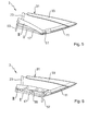
Fig. 2 , wobei die Hauptsäulen um einen verdeckfrontseitigen Drehpunkt gegenüber den weiteren Bauelementen des Bauelementekörpers verschwenkbar sind; - Fig. 4
- eine schematische Darstellung des in einem heckseitigen Ablageraum des Cabriolet-Fahrzeugs abgelegten Bauelementekörpers der
Fig. 3 in einer Seitenansicht; - Fig. 5
- eine vereinfachte Seitenansicht eines alternativen Ausführungsbeispiels des Bauelementekörpers der
Fig. 2 , wobei die Hauptsäulen um einen verdeckheckseitigen Drehpunkt gegenüber den weiteren Bauelementen des Bauelementekörpers verschwenkbar sind; - Fig. 6
- eine vereinfachte Seitenansicht eines alternativen Ausführungsbeispiels des Bauelementekörpers der
Fig. 2 , wobei die Hauptsäulen über einen viergelenk- mechanismus gegenüber den weiteren Bauelementen des Bauelementekörpers verlagerbar sind; - Fig. 7
- eine vereinfachte Seitenansicht eines alternativen Ausführungsbeispiels des Bauelementekörpers der
Fig. 2 , wobei die Hauptsäulen über eine Kulissenführung gegenüber den weiteren Bauelementen des Bauelementekörpers verlagerbar sind; und - Fig. 8
- eine vereinfachte Seitenansicht eines alternativen Ausführungsbeispiels des Bauelementekörpers der
Fig. 2 , wobei die Hauptsäulen zusammen mit dem Eckspriegel eine Einheit bilden, welche mittels eines Viergelenkmechanismus gegenüber den weiteren Bauelementen des Bauelementekörpers verlagerbar ist.
- Fig. 1
- a simplified three-dimensional view of a section of a convertible vehicle with a soft-top roof without a top cover, wherein the soft-top top is shown in a passenger compartment spanning, closed position;
- Fig. 2
- a simplified three-dimensional representation of a rear-side portion of the hood of the
Fig.1 wherein a rear window, a fabric support bracket, a corner hoop and the main pillars form a component body; - Fig. 3
- a simplified side view of the component body of
Fig. 2 , wherein the main columns are pivotable about a hood front side pivot point with respect to the other components of the component body; - Fig. 4
- a schematic representation of the stored in a rear-side storage compartment of the convertible vehicle component body of
Fig. 3 in a side view; - Fig. 5
- a simplified side view of an alternative embodiment of the component body of
Fig. 2 , wherein the main pillars are pivotable about a hood rear side pivot point relative to the other components of the component body; - Fig. 6
- a simplified side view of an alternative embodiment of the component body of
Fig. 2 with the main columns over a four-bar linkage mechanism are displaceable relative to the other components of the component body; - Fig. 7
- a simplified side view of an alternative embodiment of the component body of
Fig. 2 , wherein the main columns are displaceable over a slotted guide relative to the other components of the component body; and - Fig. 8
- a simplified side view of an alternative embodiment of the component body of
Fig. 2 , wherein the main columns together with the Eckspriegel form a unit which is displaceable by means of a four-bar mechanism with respect to the other components of the component body.
In
Seitlich wird das Verdeck 3 von seitlichen Dachrahmenelementen 15 begrenzt, welche bei geschlossenem Verdeck 3 fluchtend verdeckfrontseitig an eine einer linken Fahrzeugseite angeordneten C-Säule bzw. Hauptsäule 17 und eine einer rechten Fahrzeugseite angeordneten Hauptsäule 19 des Verdecks 3 anschließen. In Verdeckquerrichtung sind die seitlichen Dachrahmenelemente 15 und die ebenfalls Dachrahmenelemente darstellenden Hauptsäulen 17, 19 über Querspriegel 21 verbunden, wobei ein bei geschlossenem Verdeck 3 hinterster Querspriegel als Eckspriegel 23 bezeichnet wird.Laterally, the top 3 is bounded by lateral
Das Verdeck 3 kann ausgehend von der gezeigten, einen Fahrgastraum 25 überdeckenden, geschlossenen Position mittels einer nicht näher dargestellten, mit einem Verdeckgestänge 29 zusammenwirkenden Antriebseinrichtung in eine den Fahrgastraum 7 freigebende, offene Position verlagert werden, in welcher das Verdeck 3 in einem heckseitigen Ablageraum 27 verstaut ist. Der heckseitige Ablageraum 27 ist vorliegend von dem heckseitigen Deckel 13 verschließbar.The top 3 can be moved starting from the shown, a
Ein heckseitiger Teil des Verdecks 3 bildet dabei einen in der
Die Heckscheibe 33 ist über einen Heckscheibenrahmen 35 mit dem Bauelementekörper 31 verbunden, wobei der Heckscheibenrahmen 35 in einem von dem flexiblen Verdeckbezug 5 überspannten Bereich 39 vorliegend zusätzlich über Verbindungsstreben 37 mit dem Eckspriegel 23 verbunden ist.The
Weiterhin ist eine Einlage 41 vorgesehen, welche mit dem Eckspriegel 23 und der Hauptsäule 17 zusammenwirkt.Furthermore, an insert 41 is provided, which cooperates with the
In der
Die Hauptsäulen 17, 19 sind vorliegend an einem nicht näher dargestellten Lenker des Verdeckgestänges 29 drehbar gelagert und über eine in einem heckseitigen Bereich der Hauptsäulen 17, 19 angreifende, als Zug-Druckstange 45 ausgebildete und nur schematisch dargestellte Antriebsstange zwangsgesteuert an das Verdeckgestänge 29 angebunden, so dass sie bei einer Verdecköffnungs- oder schließbewegung über die Verdeckkinematik mitbewegt werden.The
Bei einer Überführung des Verdecks 3 zwischen seiner geschlossenen Position und seiner offenen Position bleibt der Bauelementekörper 31 bestehen, d. h. die Bauelemente 11, 17, 19, 23, 33 werden nicht gegensinnig zueinander bewegt. Im Prinzip behalten die Bauelemente 11, 23, 33 des Bauelementekörpers 31 ihre relative Position zueinander bei, nur die Hauptsäulen 17, 19 werden bei einer Verdecköffnungs- bzw. schließbewegung gegenüber den restlichen Bauelementen 11, 23, 33 verschwenkt. Der Bauelementekörper 31 behält somit mit Ausnahme der Hauptsäulen 17, 19 seine Form bei.In a transfer of the top 3 between its closed position and its open position, the
Die gesamte Verlagerung des Bauelementekörpers 31 als Einheit ermöglicht einen vorteilhafterweise einfachen Verdeckmechanismus. Der Bauelementekörper 31 kann über einen Viergelenkmechanismus an einem nicht näher ersichtlichen Hauptlager des Verdecks 3 angelenkt sein und wahlweise als unterstes oder oberstes Bauteil des Verdecks 3 in dem heckseitigen Ablageraum 27 positioniert werden. Bei einer Verdecköffnungsbewegung wird der Bauelementekörper 31 im Wesentlichen parallel heckwärts abwärts verlagert, ohne ein nennenswertes Verkippen um eine Fahrzeugquerachse durchzuführen.The entire displacement of the
Die Hauptsäulen 17, 19 stehen bei geschlossenem Verdeck 3 optisch vorteilhaft wenigstens annähernd parallel zu der Heckscheibe 33, wodurch sich eine C-Säulenoptik ergibt, die einem Coupe oder einem Cabriolet-Fahrzeug mit Hard-Top-Verdeck entspricht. Die Hauptsäulen 17, 19 können dadurch für ein gute Sicht nach schräg hinten sehr schmal und coupéartig und die Heckscheibe 33 vorteilhafterweise groß ausgebildet sein.The
Die Heckscheibe 33 wird gleichsinnig zu den Hauptsäulen 17, 19 abgelegt, nämlich wenigstens annähernd horizontal und mit ihrer bei geschlossenem Verdeck 3 dem Fahrgastraum 25 zugewandten Seite nach unten zeigend. Das Verdeck 3 ist dadurch im abgelegten Zustand besonders flach.The
Die bei geschlossenem Verdeck 3 fahrzeugfrontseitig der Hauptsäulen 17, 19 angeordneten seitlichen Dachrahmenelemente 15 können über einen Viergelenkmechanismus an den Bauelementekörper 31 angebunden sein, so dass sie bei Beginn einer Dachöffnungsbewegung heckwärts und abwärts unter die Hauptsäulen 17, 19 verlagert werden.The lateral
Bei mehrteiligen vor den Hauptsäulen angeordneten seitlichen Dachrahmenelementen können diese alternativ hierzu über eine jeweils drehbare Lagerung Z-artig unter den Bauelementekörper verlagert werden.In the case of multi-part lateral roof frame elements arranged in front of the main columns, they can alternatively be displaced under a Z-type under the component body via a respective rotatable bearing.
In einer weiteren Alternative können die seitlichen Dachrahmenelemente über Viergelenkmechanismen miteinander verbunden sein und direkt über einen Viergelenkmechanismus an das Hauptlager angebunden sein, wobei die seitlichen Dachrahmenelemente bei einer Verdecköffnung unter den an die seitlichen Dachrahmenelemente angebundenen Bauelementekörper verlagert werden. Selbstverständlich können weitere verdeckmechanismen eingesetzt werden.In a further alternative, the lateral roof frame elements may be connected to each other via four-bar linkages and connected directly to the main bearing via a four-bar linkage, wherein the side roof frame elements are displaced under a roof opening under the component bodies connected to the lateral roof frame elements. Of course, other convertible top mechanisms can be used.
In der
Bei einer in der
Zur Bewegung der Hauptsäulen 17, 19 gegenüber dem Bauelementekörper 31 sind die Hauptsäulen 17, 19 in einem verdeckfrontseitigen Bereich über eine schematisch dargestellte, als Zug-Druckstange 53 ausgebildete Antriebsstange zwangsgesteuert an das Verdeckgestänge 29 angebunden.To move the
Auch hier wird durch die Bewegung der Hauptsäulen 17, 19 von der ersten Position I in die zweite Position II ein von dem Bauelementekörper 31 benötigter Ablageraum an den heckseitigen Ablageraum 27 angepasst und die Höhe des Bauelementekörpers 31 reduziert.Here, too, by the movement of the
Die Hauptsäulen 17, 19 sind in einer weiteren alternativen Ausgestaltung der Erfindung mittels einer schematisch dargestellten Kulissenführung 59 gegenüber den weiteren Bauelementen 11, 23, 33 des Bauelementekörpers 31 beweglich gelagert. Dabei sind insbesondere zwei linear ausgebildete Kulissenbahnen 61, 63 vorgesehen, welche vorliegend an einem Lenker des Verdeckgestänges 29 angeordnet sind und in welchen die Hauptsäulen 17, 19 gelagert sind. Eine erste Kulissenbahn 61 ist dabei in einem verdeckfrontseitigen Bereich der Hauptsäulen 17, 19 und eine zweite Kulissenbahn 63 in einem verdeckheckseitigen Bereich der Hauptsäulen 17, 19 angeordnet.The
Zur translatorischen Bewegung der Hauptsäulen 17, 19 zwischen der ersten Position I bei geschlossenem Verdeck 3 und der zweiten Position II bei offenem Verdeck 3 sind die Hauptsäulen 17, 19 über eine nur schematisch dargestellte und als Zug-Druckstange 65 ausgebildete Antriebsstange an das Verdeckgestänge 29 zwangsgesteuert angebunden, wobei die Zug-Druckstange 65 vorliegend in einem mittigen Bereich der Hauptsäulen 17, 19 mit diesen zusammenwirkt.For translational movement of the
Um den Bauelementekörper 31 bei einer Verdecköffnungsbewegung in seiner Länge zu verkürzen, bilden bei der in der
Auch bei dieser Ausgestaltung sind jeweils zwei Bauelemente des Bauelementekörpers 31 starr miteinander verbunden, nämlich einerseits wie bei den vorherigen Ausführungsbeispielen die Heckscheibe 33 mit dem Stoffhaltebügel 11 und andererseits die Hauptsäulen 17, 19 mit dem Eckspriegel 23.Also in this embodiment, two components of the
Claims (11)
dadurch gekennzeichnet,
dass eine aus wenigstens einem Bauelement (11, 17, 19, 23, 33, 67) des Bauelementekörpers (31) bestehende Einheit (17, 19, 67) bei einer Überführung des Verdecks (3) zwischen der geschlossenen Position und der offenen Position gegenüber den anderen Bauelementen des Bauelementekörpers (31) innerhalb von Bewegungsgrenzen, welche durch den Verdeckbezug (5) vorgegeben sind, bewegbar ist.Soft-top hood for a convertible vehicle (1) which can be moved between a closed position covering a passenger compartment (25) and an open position releasing the passenger compartment (25), comprising a flexible top cover (5) at least partially ) comprising a rear window (33), a fabric support bracket (11), a Eckspriegel (23) and main columns (17, 19), wherein the orientation of the components (11, 17, 19, 23, 33, 67) of the component body (31) to each other during a transfer of the top (3) between the closed position and the open position remains,
characterized,
in that a unit (17, 19, 67) consisting of at least one component (11, 17, 19, 23, 33, 67) of the component body (31) is located between the closed position and the open position when the convertible top (3) is transferred the other components of the component body (31) within movement limits, which are predetermined by the top cloth (5), is movable.
dadurch gekennzeichnet, 1
dass die Einheit (17, 19, 67) rotatorisch gegenüber den anderen Bauelementen bewegbar ist.Soft-top hood according to claim 1,
characterized , 1
in that the unit (17, 19, 67) is rotationally movable relative to the other components.
dadurch gekennzeichnet, 1
dass die Einheit (17, 19, 67) translatorisch gegenüber den anderen Bauelementen bewegbar ist.Soft-top hood according to claim 1,
characterized , 1
in that the unit (17, 19, 67) is movable in translation relative to the other components.
dadurch gekennzeichnet,
dass die Einheit (17, 19, 67) durch eine kombinierte rotatorische und translatorische Bewegung gegenüber den anderen Bauelementen bewegbar ist.Soft-top hood according to claim 1,
characterized,
in that the unit (17, 19, 67) is movable relative to the other components by a combined rotational and translational movement.
dass die Hauptsäulen (17, 19) die Einheit darstellen.Soft-top hood according to one of claims 1 to 4, characterized
that the main columns (17, 19) representing the unit.
dass die Hauptsäulen (17, 19) und der Eckspriegel (23) die Einheit (67) darstellen.Soft-top hood according to one of claims 1 to 4, characterized
that the main column (17, 19) and the corner bow (23) representing the unit (67).
dass der Stoffhaltebügel (11) die Einheit darstellt.Soft-top hood according to one of claims 1 to 4, characterized
that the fabric support bracket (11) represents the unit.
dass die Einheit (17, 19, 67) bei einer Überführung des Verdecks (3) zwischen seiner geschlossenen Position und seiner offenen Position durch eine Anbindung an ein Verdeckgestänge (29) zwangsgesteuert ist.Soft-top hood according to one of claims 1 to 7, characterized
in that the unit (17, 19, 67) is force-controlled in the event of a transfer of the convertible top (3) between its closed position and its open position by a connection to a convertible top linkage (29).
dass ein separater Antrieb zur Bewegung der Einheit (17, 19, 67) vorgesehen ist.Soft-top hood according to one of claims 1 to 7, characterized
that a separate drive for moving the unit (17, 19, 67) is provided.
dass mehrere bewegliche Einheiten (17, 19, 67) vorgesehen sind.Soft-top hood according to one of claims 1 to 9, characterized
that a plurality of movable units (17, 19, 67) are provided are.
dass wenigstens zwei Bauelemente des Bauelementekörpers (31) starr miteinander verbunden sind.Soft-top hood according to one of claims 1 to 10, characterized
in that at least two components of the component body (31) are rigidly connected to one another.
Applications Claiming Priority (1)
| Application Number | Priority Date | Filing Date | Title |
|---|---|---|---|
| DE201010014921 DE102010014921A1 (en) | 2010-04-14 | 2010-04-14 | Soft-top hood for a convertible vehicle |
Publications (3)
| Publication Number | Publication Date |
|---|---|
| EP2377708A2 true EP2377708A2 (en) | 2011-10-19 |
| EP2377708A3 EP2377708A3 (en) | 2013-07-03 |
| EP2377708B1 EP2377708B1 (en) | 2016-06-08 |
Family
ID=44279713
Family Applications (1)
| Application Number | Title | Priority Date | Filing Date |
|---|---|---|---|
| EP11162108.2A Active EP2377708B1 (en) | 2010-04-14 | 2011-04-12 | Soft top for a convertible vehicle |
Country Status (2)
| Country | Link |
|---|---|
| EP (1) | EP2377708B1 (en) |
| DE (1) | DE102010014921A1 (en) |
Families Citing this family (1)
| Publication number | Priority date | Publication date | Assignee | Title |
|---|---|---|---|---|
| DE102012021553A1 (en) * | 2012-11-02 | 2014-05-08 | Valmet Automotive Oy | Cover i.e. flexible convertible roof cover, for cabriolet vehicle, has force loading device coacting with steering wheel such that loading device counteracts downward movement of front end against window during upward pivoting of bracket |
Citations (1)
| Publication number | Priority date | Publication date | Assignee | Title |
|---|---|---|---|---|
| DE102007020180A1 (en) | 2007-04-28 | 2008-10-30 | Wilhelm Karmann Gmbh | Cabriolet vehicle, has cover with main columns extending out obliquely from window spandrel |
Family Cites Families (3)
| Publication number | Priority date | Publication date | Assignee | Title |
|---|---|---|---|---|
| US2833593A (en) * | 1953-12-28 | 1958-05-06 | Gen Motors Corp | Convertible top with an inflatable covering |
| DE4124813C1 (en) * | 1991-07-26 | 1992-06-17 | Mercedes-Benz Aktiengesellschaft, 7000 Stuttgart, De | |
| DE102006002030B3 (en) * | 2006-01-13 | 2007-07-12 | Edscha Cabrio-Dachsysteme Gmbh | Motor vehicle`s e.g. convertible vehicle, rear window controlling device, has drive guide driven about fixed bearing, and coupling guide guided about another fixed bearing, where bearings are arranged at roof unit |
-
2010
- 2010-04-14 DE DE201010014921 patent/DE102010014921A1/en not_active Withdrawn
-
2011
- 2011-04-12 EP EP11162108.2A patent/EP2377708B1/en active Active
Patent Citations (1)
| Publication number | Priority date | Publication date | Assignee | Title |
|---|---|---|---|---|
| DE102007020180A1 (en) | 2007-04-28 | 2008-10-30 | Wilhelm Karmann Gmbh | Cabriolet vehicle, has cover with main columns extending out obliquely from window spandrel |
Also Published As
| Publication number | Publication date |
|---|---|
| EP2377708A3 (en) | 2013-07-03 |
| EP2377708B1 (en) | 2016-06-08 |
| DE102010014921A1 (en) | 2011-10-20 |
Similar Documents
| Publication | Publication Date | Title |
|---|---|---|
| DE10205342B4 (en) | Cabriolet motor vehicle with foldable hardtop | |
| EP1831043B1 (en) | Cabriolet vehicle having a movable rear-window shelf | |
| DE10152944A1 (en) | Convertible top for a convertible vehicle | |
| DE10043703A1 (en) | Lowerable vehicle roof | |
| DE10254366A1 (en) | motor vehicle | |
| EP1893433B1 (en) | Convertible with a roof which can be stored below a covering | |
| EP1971501B1 (en) | Folding top for a motor vehicle | |
| EP1945474B1 (en) | Displaceable roof part of an openable vehicle roof | |
| EP1331122A1 (en) | Retractable hardtop vehicle roof | |
| WO2005095134A1 (en) | Convertible | |
| EP1897731B1 (en) | Foldable soft top with the soft top material attached along the frame | |
| DE10249299B4 (en) | Storage compartment cover of a convertible | |
| DE102017128136B4 (en) | A convertible top, comprising a headliner assembly | |
| WO2008061578A1 (en) | Cover system for a convertible vehicle | |
| EP2377708B1 (en) | Soft top for a convertible vehicle | |
| DE102009048353A1 (en) | Soft-folding top for two seater cabriolet-vehicle, has folding top elements running in folding top rail direction and exhibiting folding top parts that are pivoted to each other in opposite rotation direction in opening position of top | |
| EP1656273B1 (en) | Convertible | |
| EP1683670B1 (en) | Retractable hard top roof for a convertible car | |
| EP1800928B1 (en) | Multi-part roof for vehicles with open superstructure | |
| DE102015106311B4 (en) | Convertible top with coupling handlebar unit | |
| EP1897724B1 (en) | Top for a convertible | |
| EP2889171A1 (en) | Soft top for a convertible | |
| DE102005009720A1 (en) | Hood for a convertible vehicle | |
| EP1737690B1 (en) | Convertible | |
| DE102007060363B4 (en) | Motor vehicle with a rear window comprehensive unit |
Legal Events
| Date | Code | Title | Description |
|---|---|---|---|
| AK | Designated contracting states |
Kind code of ref document: A2 Designated state(s): AL AT BE BG CH CY CZ DE DK EE ES FI FR GB GR HR HU IE IS IT LI LT LU LV MC MK MT NL NO PL PT RO RS SE SI SK SM TR |
|
| AX | Request for extension of the european patent |
Extension state: BA ME |
|
| PUAI | Public reference made under article 153(3) epc to a published international application that has entered the european phase |
Free format text: ORIGINAL CODE: 0009012 |
|
| RAP1 | Party data changed (applicant data changed or rights of an application transferred) |
Owner name: VALMET AUTOMOTIVE OY |
|
| PUAL | Search report despatched |
Free format text: ORIGINAL CODE: 0009013 |
|
| AK | Designated contracting states |
Kind code of ref document: A3 Designated state(s): AL AT BE BG CH CY CZ DE DK EE ES FI FR GB GR HR HU IE IS IT LI LT LU LV MC MK MT NL NO PL PT RO RS SE SI SK SM TR |
|
| AX | Request for extension of the european patent |
Extension state: BA ME |
|
| RIC1 | Information provided on ipc code assigned before grant |
Ipc: B60J 7/12 20060101AFI20130524BHEP |
|
| 17P | Request for examination filed |
Effective date: 20131217 |
|
| RBV | Designated contracting states (corrected) |
Designated state(s): AL AT BE BG CH CY CZ DE DK EE ES FI FR GB GR HR HU IE IS IT LI LT LU LV MC MK MT NL NO PL PT RO RS SE SI SK SM TR |
|
| 17Q | First examination report despatched |
Effective date: 20150423 |
|
| GRAP | Despatch of communication of intention to grant a patent |
Free format text: ORIGINAL CODE: EPIDOSNIGR1 |
|
| INTG | Intention to grant announced |
Effective date: 20151130 |
|
| GRAS | Grant fee paid |
Free format text: ORIGINAL CODE: EPIDOSNIGR3 |
|
| GRAA | (expected) grant |
Free format text: ORIGINAL CODE: 0009210 |
|
| AK | Designated contracting states |
Kind code of ref document: B1 Designated state(s): AL AT BE BG CH CY CZ DE DK EE ES FI FR GB GR HR HU IE IS IT LI LT LU LV MC MK MT NL NO PL PT RO RS SE SI SK SM TR |
|
| REG | Reference to a national code |
Ref country code: GB Ref legal event code: FG4D Free format text: NOT ENGLISH |
|
| REG | Reference to a national code |
Ref country code: CH Ref legal event code: EP |
|
| REG | Reference to a national code |
Ref country code: IE Ref legal event code: FG4D Free format text: LANGUAGE OF EP DOCUMENT: GERMAN |
|
| REG | Reference to a national code |
Ref country code: AT Ref legal event code: REF Ref document number: 804949 Country of ref document: AT Kind code of ref document: T Effective date: 20160715 |
|
| REG | Reference to a national code |
Ref country code: DE Ref legal event code: R096 Ref document number: 502011009901 Country of ref document: DE |
|
| REG | Reference to a national code |
Ref country code: LT Ref legal event code: MG4D |
|
| REG | Reference to a national code |
Ref country code: NL Ref legal event code: MP Effective date: 20160608 |
|
| PG25 | Lapsed in a contracting state [announced via postgrant information from national office to epo] |
Ref country code: FI Free format text: LAPSE BECAUSE OF FAILURE TO SUBMIT A TRANSLATION OF THE DESCRIPTION OR TO PAY THE FEE WITHIN THE PRESCRIBED TIME-LIMIT Effective date: 20160608 Ref country code: LT Free format text: LAPSE BECAUSE OF FAILURE TO SUBMIT A TRANSLATION OF THE DESCRIPTION OR TO PAY THE FEE WITHIN THE PRESCRIBED TIME-LIMIT Effective date: 20160608 Ref country code: NO Free format text: LAPSE BECAUSE OF FAILURE TO SUBMIT A TRANSLATION OF THE DESCRIPTION OR TO PAY THE FEE WITHIN THE PRESCRIBED TIME-LIMIT Effective date: 20160908 |
|
| PG25 | Lapsed in a contracting state [announced via postgrant information from national office to epo] |
Ref country code: LV Free format text: LAPSE BECAUSE OF FAILURE TO SUBMIT A TRANSLATION OF THE DESCRIPTION OR TO PAY THE FEE WITHIN THE PRESCRIBED TIME-LIMIT Effective date: 20160608 Ref country code: GR Free format text: LAPSE BECAUSE OF FAILURE TO SUBMIT A TRANSLATION OF THE DESCRIPTION OR TO PAY THE FEE WITHIN THE PRESCRIBED TIME-LIMIT Effective date: 20160909 Ref country code: RS Free format text: LAPSE BECAUSE OF FAILURE TO SUBMIT A TRANSLATION OF THE DESCRIPTION OR TO PAY THE FEE WITHIN THE PRESCRIBED TIME-LIMIT Effective date: 20160608 Ref country code: ES Free format text: LAPSE BECAUSE OF FAILURE TO SUBMIT A TRANSLATION OF THE DESCRIPTION OR TO PAY THE FEE WITHIN THE PRESCRIBED TIME-LIMIT Effective date: 20160608 Ref country code: NL Free format text: LAPSE BECAUSE OF FAILURE TO SUBMIT A TRANSLATION OF THE DESCRIPTION OR TO PAY THE FEE WITHIN THE PRESCRIBED TIME-LIMIT Effective date: 20160608 Ref country code: SE Free format text: LAPSE BECAUSE OF FAILURE TO SUBMIT A TRANSLATION OF THE DESCRIPTION OR TO PAY THE FEE WITHIN THE PRESCRIBED TIME-LIMIT Effective date: 20160608 |
|
| PG25 | Lapsed in a contracting state [announced via postgrant information from national office to epo] |
Ref country code: CZ Free format text: LAPSE BECAUSE OF FAILURE TO SUBMIT A TRANSLATION OF THE DESCRIPTION OR TO PAY THE FEE WITHIN THE PRESCRIBED TIME-LIMIT Effective date: 20160608 Ref country code: RO Free format text: LAPSE BECAUSE OF FAILURE TO SUBMIT A TRANSLATION OF THE DESCRIPTION OR TO PAY THE FEE WITHIN THE PRESCRIBED TIME-LIMIT Effective date: 20160608 Ref country code: SK Free format text: LAPSE BECAUSE OF FAILURE TO SUBMIT A TRANSLATION OF THE DESCRIPTION OR TO PAY THE FEE WITHIN THE PRESCRIBED TIME-LIMIT Effective date: 20160608 Ref country code: IS Free format text: LAPSE BECAUSE OF FAILURE TO SUBMIT A TRANSLATION OF THE DESCRIPTION OR TO PAY THE FEE WITHIN THE PRESCRIBED TIME-LIMIT Effective date: 20161008 Ref country code: IT Free format text: LAPSE BECAUSE OF FAILURE TO SUBMIT A TRANSLATION OF THE DESCRIPTION OR TO PAY THE FEE WITHIN THE PRESCRIBED TIME-LIMIT Effective date: 20160608 Ref country code: EE Free format text: LAPSE BECAUSE OF FAILURE TO SUBMIT A TRANSLATION OF THE DESCRIPTION OR TO PAY THE FEE WITHIN THE PRESCRIBED TIME-LIMIT Effective date: 20160608 |
|
| PG25 | Lapsed in a contracting state [announced via postgrant information from national office to epo] |
Ref country code: PT Free format text: LAPSE BECAUSE OF FAILURE TO SUBMIT A TRANSLATION OF THE DESCRIPTION OR TO PAY THE FEE WITHIN THE PRESCRIBED TIME-LIMIT Effective date: 20161010 Ref country code: SM Free format text: LAPSE BECAUSE OF FAILURE TO SUBMIT A TRANSLATION OF THE DESCRIPTION OR TO PAY THE FEE WITHIN THE PRESCRIBED TIME-LIMIT Effective date: 20160608 Ref country code: PL Free format text: LAPSE BECAUSE OF FAILURE TO SUBMIT A TRANSLATION OF THE DESCRIPTION OR TO PAY THE FEE WITHIN THE PRESCRIBED TIME-LIMIT Effective date: 20160608 |
|
| REG | Reference to a national code |
Ref country code: DE Ref legal event code: R097 Ref document number: 502011009901 Country of ref document: DE |
|
| PLBE | No opposition filed within time limit |
Free format text: ORIGINAL CODE: 0009261 |
|
| STAA | Information on the status of an ep patent application or granted ep patent |
Free format text: STATUS: NO OPPOSITION FILED WITHIN TIME LIMIT |
|
| 26N | No opposition filed |
Effective date: 20170309 |
|
| PG25 | Lapsed in a contracting state [announced via postgrant information from national office to epo] |
Ref country code: DK Free format text: LAPSE BECAUSE OF FAILURE TO SUBMIT A TRANSLATION OF THE DESCRIPTION OR TO PAY THE FEE WITHIN THE PRESCRIBED TIME-LIMIT Effective date: 20160608 Ref country code: SI Free format text: LAPSE BECAUSE OF FAILURE TO SUBMIT A TRANSLATION OF THE DESCRIPTION OR TO PAY THE FEE WITHIN THE PRESCRIBED TIME-LIMIT Effective date: 20160608 |
|
| REG | Reference to a national code |
Ref country code: CH Ref legal event code: PL |
|
| GBPC | Gb: european patent ceased through non-payment of renewal fee |
Effective date: 20170412 |
|
| REG | Reference to a national code |
Ref country code: IE Ref legal event code: MM4A |
|
| REG | Reference to a national code |
Ref country code: FR Ref legal event code: ST Effective date: 20171229 |
|
| PG25 | Lapsed in a contracting state [announced via postgrant information from national office to epo] |
Ref country code: FR Free format text: LAPSE BECAUSE OF NON-PAYMENT OF DUE FEES Effective date: 20170502 Ref country code: MC Free format text: LAPSE BECAUSE OF FAILURE TO SUBMIT A TRANSLATION OF THE DESCRIPTION OR TO PAY THE FEE WITHIN THE PRESCRIBED TIME-LIMIT Effective date: 20160608 |
|
| PG25 | Lapsed in a contracting state [announced via postgrant information from national office to epo] |
Ref country code: GB Free format text: LAPSE BECAUSE OF NON-PAYMENT OF DUE FEES Effective date: 20170412 Ref country code: CH Free format text: LAPSE BECAUSE OF NON-PAYMENT OF DUE FEES Effective date: 20170430 Ref country code: LU Free format text: LAPSE BECAUSE OF NON-PAYMENT OF DUE FEES Effective date: 20170412 Ref country code: LI Free format text: LAPSE BECAUSE OF NON-PAYMENT OF DUE FEES Effective date: 20170430 |
|
| REG | Reference to a national code |
Ref country code: BE Ref legal event code: MM Effective date: 20170430 |
|
| PG25 | Lapsed in a contracting state [announced via postgrant information from national office to epo] |
Ref country code: IE Free format text: LAPSE BECAUSE OF NON-PAYMENT OF DUE FEES Effective date: 20170412 |
|
| PG25 | Lapsed in a contracting state [announced via postgrant information from national office to epo] |
Ref country code: BE Free format text: LAPSE BECAUSE OF NON-PAYMENT OF DUE FEES Effective date: 20170430 |
|
| REG | Reference to a national code |
Ref country code: AT Ref legal event code: MM01 Ref document number: 804949 Country of ref document: AT Kind code of ref document: T Effective date: 20170412 |
|
| PG25 | Lapsed in a contracting state [announced via postgrant information from national office to epo] |
Ref country code: AT Free format text: LAPSE BECAUSE OF NON-PAYMENT OF DUE FEES Effective date: 20170412 |
|
| PG25 | Lapsed in a contracting state [announced via postgrant information from national office to epo] |
Ref country code: MT Free format text: LAPSE BECAUSE OF FAILURE TO SUBMIT A TRANSLATION OF THE DESCRIPTION OR TO PAY THE FEE WITHIN THE PRESCRIBED TIME-LIMIT Effective date: 20160608 |
|
| PG25 | Lapsed in a contracting state [announced via postgrant information from national office to epo] |
Ref country code: AL Free format text: LAPSE BECAUSE OF FAILURE TO SUBMIT A TRANSLATION OF THE DESCRIPTION OR TO PAY THE FEE WITHIN THE PRESCRIBED TIME-LIMIT Effective date: 20160608 |
|
| PG25 | Lapsed in a contracting state [announced via postgrant information from national office to epo] |
Ref country code: HU Free format text: LAPSE BECAUSE OF FAILURE TO SUBMIT A TRANSLATION OF THE DESCRIPTION OR TO PAY THE FEE WITHIN THE PRESCRIBED TIME-LIMIT; INVALID AB INITIO Effective date: 20110412 |
|
| PG25 | Lapsed in a contracting state [announced via postgrant information from national office to epo] |
Ref country code: BG Free format text: LAPSE BECAUSE OF FAILURE TO SUBMIT A TRANSLATION OF THE DESCRIPTION OR TO PAY THE FEE WITHIN THE PRESCRIBED TIME-LIMIT Effective date: 20160608 |
|
| PG25 | Lapsed in a contracting state [announced via postgrant information from national office to epo] |
Ref country code: CY Free format text: LAPSE BECAUSE OF NON-PAYMENT OF DUE FEES Effective date: 20160608 |
|
| PG25 | Lapsed in a contracting state [announced via postgrant information from national office to epo] |
Ref country code: MK Free format text: LAPSE BECAUSE OF FAILURE TO SUBMIT A TRANSLATION OF THE DESCRIPTION OR TO PAY THE FEE WITHIN THE PRESCRIBED TIME-LIMIT Effective date: 20160608 |
|
| PG25 | Lapsed in a contracting state [announced via postgrant information from national office to epo] |
Ref country code: TR Free format text: LAPSE BECAUSE OF FAILURE TO SUBMIT A TRANSLATION OF THE DESCRIPTION OR TO PAY THE FEE WITHIN THE PRESCRIBED TIME-LIMIT Effective date: 20160608 |
|
| PG25 | Lapsed in a contracting state [announced via postgrant information from national office to epo] |
Ref country code: HR Free format text: LAPSE BECAUSE OF FAILURE TO SUBMIT A TRANSLATION OF THE DESCRIPTION OR TO PAY THE FEE WITHIN THE PRESCRIBED TIME-LIMIT Effective date: 20160608 |
|
| P01 | Opt-out of the competence of the unified patent court (upc) registered |
Effective date: 20230601 |
|
| PGFP | Annual fee paid to national office [announced via postgrant information from national office to epo] |
Ref country code: DE Payment date: 20230630 Year of fee payment: 13 |