EP2377663B1 - Batch mixer - Google Patents
Batch mixer Download PDFInfo
- Publication number
- EP2377663B1 EP2377663B1 EP10731195.3A EP10731195A EP2377663B1 EP 2377663 B1 EP2377663 B1 EP 2377663B1 EP 10731195 A EP10731195 A EP 10731195A EP 2377663 B1 EP2377663 B1 EP 2377663B1
- Authority
- EP
- European Patent Office
- Prior art keywords
- alarm
- display
- mixing
- latch
- door
- Prior art date
- Legal status (The legal status is an assumption and is not a legal conclusion. Google has not performed a legal analysis and makes no representation as to the accuracy of the status listed.)
- Not-in-force
Links
Images


Classifications
-
- B—PERFORMING OPERATIONS; TRANSPORTING
- B29—WORKING OF PLASTICS; WORKING OF SUBSTANCES IN A PLASTIC STATE IN GENERAL
- B29B—PREPARATION OR PRETREATMENT OF THE MATERIAL TO BE SHAPED; MAKING GRANULES OR PREFORMS; RECOVERY OF PLASTICS OR OTHER CONSTITUENTS OF WASTE MATERIAL CONTAINING PLASTICS
- B29B7/00—Mixing; Kneading
- B29B7/02—Mixing; Kneading non-continuous, with mechanical mixing or kneading devices, i.e. batch type
- B29B7/06—Mixing; Kneading non-continuous, with mechanical mixing or kneading devices, i.e. batch type with movable mixing or kneading devices
- B29B7/10—Mixing; Kneading non-continuous, with mechanical mixing or kneading devices, i.e. batch type with movable mixing or kneading devices rotary
- B29B7/18—Mixing; Kneading non-continuous, with mechanical mixing or kneading devices, i.e. batch type with movable mixing or kneading devices rotary with more than one shaft
- B29B7/183—Mixing; Kneading non-continuous, with mechanical mixing or kneading devices, i.e. batch type with movable mixing or kneading devices rotary with more than one shaft having a casing closely surrounding the rotors, e.g. of Banbury type
-
- B—PERFORMING OPERATIONS; TRANSPORTING
- B01—PHYSICAL OR CHEMICAL PROCESSES OR APPARATUS IN GENERAL
- B01F—MIXING, e.g. DISSOLVING, EMULSIFYING OR DISPERSING
- B01F27/00—Mixers with rotary stirring devices in fixed receptacles; Kneaders
- B01F27/60—Mixers with rotary stirring devices in fixed receptacles; Kneaders with stirrers rotating about a horizontal or inclined axis
-
- B—PERFORMING OPERATIONS; TRANSPORTING
- B01—PHYSICAL OR CHEMICAL PROCESSES OR APPARATUS IN GENERAL
- B01F—MIXING, e.g. DISSOLVING, EMULSIFYING OR DISPERSING
- B01F35/00—Accessories for mixers; Auxiliary operations or auxiliary devices; Parts or details of general application
-
- B—PERFORMING OPERATIONS; TRANSPORTING
- B01—PHYSICAL OR CHEMICAL PROCESSES OR APPARATUS IN GENERAL
- B01F—MIXING, e.g. DISSOLVING, EMULSIFYING OR DISPERSING
- B01F35/00—Accessories for mixers; Auxiliary operations or auxiliary devices; Parts or details of general application
- B01F35/71—Feed mechanisms
-
- B—PERFORMING OPERATIONS; TRANSPORTING
- B29—WORKING OF PLASTICS; WORKING OF SUBSTANCES IN A PLASTIC STATE IN GENERAL
- B29B—PREPARATION OR PRETREATMENT OF THE MATERIAL TO BE SHAPED; MAKING GRANULES OR PREFORMS; RECOVERY OF PLASTICS OR OTHER CONSTITUENTS OF WASTE MATERIAL CONTAINING PLASTICS
- B29B7/00—Mixing; Kneading
- B29B7/02—Mixing; Kneading non-continuous, with mechanical mixing or kneading devices, i.e. batch type
- B29B7/22—Component parts, details or accessories; Auxiliary operations
- B29B7/26—Component parts, details or accessories; Auxiliary operations for discharging, e.g. doors
- B29B7/263—Component parts, details or accessories; Auxiliary operations for discharging, e.g. doors from the underside in mixers having more than one rotor and a a casing closely surrounding the rotors
-
- B—PERFORMING OPERATIONS; TRANSPORTING
- B29—WORKING OF PLASTICS; WORKING OF SUBSTANCES IN A PLASTIC STATE IN GENERAL
- B29B—PREPARATION OR PRETREATMENT OF THE MATERIAL TO BE SHAPED; MAKING GRANULES OR PREFORMS; RECOVERY OF PLASTICS OR OTHER CONSTITUENTS OF WASTE MATERIAL CONTAINING PLASTICS
- B29B7/00—Mixing; Kneading
- B29B7/02—Mixing; Kneading non-continuous, with mechanical mixing or kneading devices, i.e. batch type
- B29B7/22—Component parts, details or accessories; Auxiliary operations
- B29B7/28—Component parts, details or accessories; Auxiliary operations for measuring, controlling or regulating, e.g. viscosity control
- B29B7/283—Component parts, details or accessories; Auxiliary operations for measuring, controlling or regulating, e.g. viscosity control measuring data of the driving system, e.g. torque, speed, power
-
- B—PERFORMING OPERATIONS; TRANSPORTING
- B29—WORKING OF PLASTICS; WORKING OF SUBSTANCES IN A PLASTIC STATE IN GENERAL
- B29B—PREPARATION OR PRETREATMENT OF THE MATERIAL TO BE SHAPED; MAKING GRANULES OR PREFORMS; RECOVERY OF PLASTICS OR OTHER CONSTITUENTS OF WASTE MATERIAL CONTAINING PLASTICS
- B29B7/00—Mixing; Kneading
- B29B7/74—Mixing; Kneading using other mixers or combinations of mixers, e.g. of dissimilar mixers ; Plant
- B29B7/7476—Systems, i.e. flow charts or diagrams; Plants
- B29B7/7495—Systems, i.e. flow charts or diagrams; Plants for mixing rubber
Definitions
- the present invention relates to an internal batch mixer.
- Patent Literature 1 An example of a conventional internal batch mixer according to the preamble of claim 1 is disclosed in the following Patent Literature 1.
- a mixing chamber is formed inside a casing, and mixing rotors are disposed within the mixing chamber.
- the casing includes a discharge opening formed to extend in the axial direction of the mixing rotor, and a drop door provided to open and close the discharge opening.
- the drop door prevents outflow of a material by blocking the discharge opening during mixing of the material within the mixing chamber. When the material mixed in the mixing chamber is discharged, the drop door is rotated and opened downwardly.
- This internal batch mixer further includes a latch device that is a lock mechanism for the drop door.
- the latch device includes a latch and a hydraulic cylinder.
- the latch is installed to move forward and backward so as to slide relative to the drop door.
- the drop door is locked by pressing a contact surface of the latch onto a contact surface of the drop door by the hydraulic cylinder, and the airtightness within the mixing chamber is consequently maintained.
- the latch is retracted, the drop door becomes openable.
- the conventional visual confirmation of wear status for the contact parts has been performed also by installing a scale plate on a base part of the mixer, attaching a landmark member to a piston rod of the hydraulic cylinder, and comparing a position of the landmark member with a scale of the scale plate.
- the hydraulic cylinder is generally in a location distant from the work area of a mixer's operator during mixing operation, it is troublesome for the operator to perform the above-mentioned confirmation during the mixing operation.
- the scale plate is generally covered with a dust collecting cover or the like, the confirmation operation or the readjustment operation is not easy.
- the dust collecting cover may be provided with a switch of a safety device. In this case, it is difficult to perform the above-mentioned confirmation operation during the operation of the mixer since the mixer is shut down when the dust collecting cover is opened during the operation.
- the confirmation of the wear status, or the confirmation of the scale plate or the like, can be delayed depending on the operation cycle of the mixer. If the wear of the contact part is left in the meantime, damage on machine components such as deformation of a thin portion at the edge of the discharge opening, that is to contact with the drop door in the casing, is caused when the latch mechanism is, for example, of toggle type. When the latch mechanism is of slide type, also, the wear is similarly caused in the contact area between the door and the latch. If the replacement time of contact part is missed, the casing or the like that is a durable component is also damaged. Since it is generally difficult to continuously grasp the wear status with respect to such a contact part in the latch mechanism, the replacement time thereof can be hardly predicted. In this way, neglect of the wear status in the contact area causes damages on machine components in both the toggle type and the slide type of latch mechanisms.
- Patent Literature 5 discloses a clutch wear amount display device having the purpose of informing an operator of a clutch wear amount.
- Patent Literature 2 discloses an internal batch mixer provided with a seal mechanism.
- the seal mechanism prevents mixing material within a mixing chamber from leaking out of the mixing chamber from an area in the vicinity of an end portion of a mixing rotor within the mixing chamber.
- This seal mechanism includes a seal member which prevents the leak of mixing material out of the mixing chamber by being pressed onto the end portion of the rotor in the axial direction of the rotor.
- the seal member is composed of a rotation-side seal member fixed to an end surface of the rotor, and a fixed-side seal member fixed to an end surface of a dust stop ring through which the rotor shaft is inserted.
- These rotation-side seal member and fixed-side seal member are consumable members which are worn away through mutual sliding.
- one of these seal members is formed by use of a material consisting of a resin compound filled with graphite or short carbon fiber not more than 1/2 inch in fiber length. This allows a reduced value of friction coefficient of the sliding surfaces of both the seal members to suppress the heat generation or wear of both the seal members that are consumable members.
- Patent Literature 3 One of techniques relating to the seal mechanism for internal batch mixer is described in the following Patent Literature 3.
- the heat generation or wear of the seal members is suppressed by rotating a first sleeve having a frictional wearing member fixed to an end surface thereof, which corresponds to the above-mentioned fixed-side seal member, in a rotor rotating direction at a rotating speed lower than the rotating speed of the rotor shaft, thereby reducing the mutual sliding speed of the seal members.
- Patent Literature 4 Another technique relating to the seal mechanism is also described in the following Patent Literature 4.
- internal pressure of the mixing chamber is measured, and seal pressure, or biasing force of a seal ring to a collar ring, is appropriately adjusted in response to the measured value of pressure by an adjustment means having a hydraulic cylinder.
- seal pressure or biasing force of a seal ring to a collar ring
- Patent Literatures 2 to 4 Each of the techniques descried in Patent Literatures 2 to 4 is intended to extend the life of seal members that are consumable members by preventing the wear of the seal members.
- these seal members are consistently consumable members. Therefore, these seal members wear down little by little, and reach the end of their lives at some stage. In other words, the seal members are members which reach their application limits at some stage.
- the operator hardly confirm sliding seal portions of the seal members during the mixing operation of the mixer since the position of the seal members is distant from the operator's work area during the operation. For grasping the abrasion loss of the seal members, further, the operator must confirm a depth of wear as small as several mm.
- An object of the present invention is to provide an internal batch mixer capable of solving the above-mentioned problems.
- the other object of the present invention is to provide an internal batch mixer, which facilitates grasp of wear level of a wearing member (consumable member) even during the operation of the internal batch mixer.
- the internal batch mixer 1 includes: a mixing device 1a for mixing material; a display device 5 for displaying displacement information of a latch member 41 and alarm (warning information) which will be described later; and a storage device 6 for storing a set value which will be described later.
- the mixing device 1a includes a casing 2, two rotors 2r, a drop door 3, a latch mechanism 4, and a support base 7.
- the internal batch mixer 1 according to this embodiment is a two-shaft batch mixer, and is used, for example, for mixing of rubber raw material.
- the material to be mixed is supplied into the casing 2 through a material feed opening 2j, which is formed in an upper portion of the casing 2, by a floating weight (not shown) provided within a hopper (not shown) so as to be capable of rising and lowering.
- the two rotors 2r formed of a metallic material are disposed within the casing 2.
- the two rotors 2r are mixing rotors, which are rotated in mutually different directions by receiving a power from a motor not shown (refer to the directions of arrows in Fig. 1 ).
- the material is mixed within the casing 2 by this rotation of the two rotors 2r.
- the mixed material is discharged through a material discharge opening 2h formed in a lower portion of the casing 2.
- the material discharge opening 2h is opened by the drop door 3 rotating downward to a discharge position shown by the broken line in Fig. 1 , whereby the material can be discharged out of the casing 2.
- the drop door 3 is put into a latched state by the function of the latch mechanism 4. In the latched state, the drop door 3 blocks the material discharge opening 2h and cannot be opened. When the material is discharged, the latch mechanism releases the latched state, whereby the drop door 3 becomes openable.
- the internal batch mixer 1 of this embodiment is configured so that display of displacement information of the latch member 41 (to be described later) and alarm display can be performed by the display device 5.
- display of displacement information of the latch member 41 to be described later
- alarm display can be performed by the display device 5.
- the casing 2 that is a body part of the internal batch mixer 1, is composed of a metallic material.
- the casing 2 is supported by the support base 7 made of metal.
- Two mixing chambers 2s are formed inside the casing 2.
- Each of the mixing chambers 2s is formed in a substantially columnar shape, and laterally juxtaposed as shown in Fig. 1 while extending in parallel to each other.
- Each rotor 2r is disposed within each mixing chamber 2s so as to extend in the same direction as the mixing chamber 2s.
- the material feed opening 2j for supplying the material to be mixed is formed at an upper portion of the casing 2.
- the material discharge opening 2h for discharging the material which has been mixed is formed at a lower portion of the casing 2.
- the material discharge opening 2h is formed to extend along the axial direction of the rotor 2r. In the casing 2, the material feed opening 2j, the two mixing chambers 2s and the material discharge opening 2h communicate with each other.
- the drop door 3 is formed of a metallic material, and functions as a lid member for blocking the material discharge opening 2h of the casing 2. This drop door 3 falls into the concept of the door in the present invention.
- the drop door 3 is provided to be rotatable around a rotary shaft 3s. Concretely, the rotary shaft 3s is fixed to the drop door 3.
- the rotary shaft 3s is supported by the support base 7 in a rotatable state.
- the axial direction of the rotary shaft 3s is parallel to the axial direction of the rotor 2r.
- the drop door 3 opens and closes the material discharge opening 2h by rotating around the rotary shaft 3s, and blocks the material discharge opening 2h when it is in a closed state.
- the rotary shaft 3s falls into the concept of the shaft in the present invention.
- the drop door 3 includes a tip section 3v and a projecting portion 3t.
- the tip section 3v is provided to protrude to the inside of the casing 2 in a state where the drop door 3 blocks the material discharge opening 2h.
- the tip section 3v is formed to extend along the axial direction of the rotor 2r.
- the tip section 3v enters to the inside of the material discharge opening 2h.
- two surfaces 3r facing the two rotors 2r of the tip section 3v, or the surfaces 3r at both lateral sides of the tip section 3v in Fig. 1 constitute the wall surface of the two mixing chambers 2s together with the inner surface of the casing 2.
- two contact surfaces 3w are formed below the two surfaces 3r.
- the two contact surfaces 3w contact with the inner wall surface of the material discharge opening 2h in the closed state of the drop door 3.
- the projecting portion 3t is a part to contact with a contact portion 41s (latch member 41) provided on a piston rod 41b which will be described later. This projecting portion 3t is formed to protrude toward the contact portion 41s in the closed state of the drop door 3.
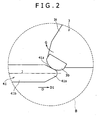
- the projecting portion 3t includes, as shown in Figs. 1 and 2 , a metallic contact plate 3b.
- the contact plate 3b of the projecting portion 3t contacts with the contact portion 41s.
- the contact plate 3b is disposed at the tip of the projecting portion 3t or at a part closest to the contact portion 41s of the projecting portion 3t.
- the surface of the contact plate 3b is formed in a curved shape, concretely, as a part of a spherical surface.
- the contact plate 3b is fixed to the body of the projecting portion 3t by use of a bolt not shown. Namely, the contact plate 3b is attachable and detachable.
- the contact plate 3b may be made of synthetic resin. Otherwise, the contact plate 3b may be omitted.
- a latch mechanism 4 holds, during mixing operation, the drop door 3 in a latched state, that is, a state in which the latch member 41 presses the drop door 3 onto the casing 2 so that the drop door 3 blocks the material discharge opening 2h and cannot be opened.
- the latch mechanism 4 releases the latched state of the drop door 3 when the material mixed within the casing 2 is discharged out of the casing 2.
- the latch mechanism 4 includes the latch member 41, a hydraulic cylinder 42, and a linear sensor 43.
- the hydraulic cylinder 42 falls into the concept of the linear actuator in the present invention.
- This hydraulic cylinder 42 includes a piston rod 41b, a piston 41p and a cylindrical body 45.
- the piston rod 41b is inserted into the cylindrical body 45.
- the piston 41p is set inside the cylindrical body 45.
- the cylindrical body 45 functions as a support for the whole hydraulic cylinder 42 and also guides the piston 41p and the piston rod 41b along the axial direction thereof.
- the cylindrical body 45 is fixed to a base 4B.
- the base 4B is formed integrally with the support base 7. Namely, the hydraulic cylinder 42 is positionally fixed so as not to move relative to the position of the casing 2.
- the hydraulic cylinder 42 and the support base 7 only need to be set on the same base, and the base 4B and the support base 7 may be composed of separated different members.
- the piston rod 41b is a bar-like member.
- the piston 41p is attached to the piston rod 41b inside the cylindrical body 45.
- the piston 41p and the piston rod 41b fall into the concept of the moving part in the present invention.
- the piston 41p is formed in an annular shape, and fixed while being fitted onto the piston rod 41b.
- the piston 41p and the piston rod 41b are mutually attachable and detachable.
- the piston rod 41b and the piston 41p may be formed as an integrated unit.
- the latch member 41 is provided to be contactable with the contact plate 3b of the drop door 3.
- the latch member 41 corresponds to a tip section of the piston rod 41b, or the contact portion 41s provided integrally at an end close to the drop door 3 of the piston rod 41b (refer to Figs. 1 and 2 ).
- the contact portion 41s is protruded in a tapered shape along the axial direction of the piston rod 41b. In the contact portion 41s, the diameter of a section vertical to axial direction D is reduced toward the end close to the drop door 3.
- the side surface of the contact portion 41s is formed in a conical shape, and the surface of the tip of the contact portion 41s is formed as a curved surface constituting a part of a spherical surface.
- An inclined portion 41z is formed on the upper surface of the contact portion 41s.
- the inclined portion 41z is inclined so that the distance from a center line along the axial direction D (refer to the dashed line J of Fig. 2 ) is reduced toward the tip surface of the contact portion 41s.
- the piston rod 41b is a replacement part. If the contact portion 41s wears down by contact with the contact plate 3b, only the piston rod 41b can be replaced by a new part.
- the latch member may be a member provided separately from the linear actuator as in a second embodiment which will be described later.
- the hydraulic cylinder 42 supplies power to the contact portion 41s to direct the contact portion 41s to the drop door 3 by moving the piston 41b and the piston rod 41b toward the drop door 3 with use of hydraulic pressure.
- a hydraulic circuit not shown is connected to the hydraulic cylinder 42. Hydraulic oil is supplied from the hydraulic circuit to hydraulic chambers formed on both sides across the piston 41b within the hydraulic cylinder 42.
- the hydraulic oil is supplied to the hydraulic chamber (head-side chamber) on the left side of the piston 41p in Fig. 1 .
- a permanent magnet 41m is attached to an end on the inner side of the hydraulic cylinder 42 of the piston rod 41b, or an end located oppositely to the drop door 3 of the piston rod 41b.
- the permanent magnet 41m may be attached not to the piston rod 41b but to the piston 41p.
- a magnetostrictive wire (sensor probe) 44 is disposed inside the hydraulic cylinder 42.
- the magnetostrictive wire 44 is positionally fixed relative to the cylindrical body 45 of the hydraulic cylinder 42.
- the magnetostrictive wire 44 extends along the axial direction D of the piston rod 41b.
- a guide hole is formed at the center of the piston rod 41b to extend along the axial direction D.
- the magnetostrictive wire 44 is inserted into this guide hole.
- the stroke operation of the piston rod 41b is performed in this state. Namely, the position of the permanent magnet 41m is changed relative to the positionally-fixed magnetostrictive wire 44 during the stroke movement of the piston 41b of the hydraulic cylinder 42.
- the magnetostrictive wire 44 is a metallic wire composed of nickel alloy.
- the magnetostrictive wire 44 As the material of the magnetostrictive wire, any metallic material (ferromagnetic material) which can develop the Wiedemann effect may be adopted.
- the magnetostrictive wire 44 may be composed of an alloy containing iron, cobalt, gadolinium, or the like.
- the linear sensor 43 measures distance of linear movement of the piston rod 41b by the hydraulic cylinder 42, in other words, distance of linear movement along the axial direction D of the piston rod 41b.
- the distance of linear movement of the piston rod 41b with the drop door 3 being in the latched state, or a maximum value of linear movement distance of the piston rod 41b corresponds to the stroke of the hydraulic cylinder 42.
- This stroke of the hydraulic cylinder 42 is the travel distance of the piston 41b from one end to the other end of the cylindrical body 45 in the closed state of the drop door 3.
- the "stroke" of the hydraulic cylinder 42 is, when explained with Fig. 1 , the travel distance of the piston rod 41b from the left end (one end) to the right end (the other end: the position in the latched state).
- the linear sensor 43 is electrically connected to the magnetostrictive wire 44.
- the linear sensor 43 is integrally attached to a head-side end of the hydraulic cylinder 42, or an end opposite to the drop door 3 of the cylindrical body 45 of the hydraulic cylinder 42.
- the integral attachment of the linear sensor 43 to the cylindrical body 45 of the hydraulic cylinder 42 eliminates the risk of displacement of the linear sensor 43 during the operation of the mixer.
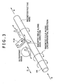
- the permanent magnet 41m of the piston rod 41b has a positional relation with the magnetostrictive wire 44 as shown in Fig. 3 .
- a magnetic field is produced along the axial direction D.
- an oblique magnetic field as shown by the dotted line is produced, around a position near the permanent magnet 41m of the magnetostrictive wire 44, by the composition of the magnetic field along the circumferential direction and the magnetic field along the axial direction D.
- This oblique magnetic field causes torsional distortion at a part near the permanent magnet 41m of the magnetostrictive wire 44. This phenomenon is called the Wiedemann effect.
- the above-mentioned torsional distortion propagates on the magnetostrictive wire 44 composed of metal as ultrasonic oscillation or sonic signal.
- the linear sensor 43 specifies the position of the permanent magnet 41m by measuring the propagation time of this ultrasonic wave or sonic wave.
- An output signal from the linear sensor 43 or a signal showing a position of the permanent magnet 41m is input to a counter (not shown) through an A/D converter (not shown). This signal is processed by the counter, whereby a numerical value representing the distance of linear movement of the piston 41p in the hydraulic cylinder 42 is derived. Output current from the linear sensor 43 is 4 to 20 mA.
- the linear sensor 43 may be connected to a programmable controller, a microprocessor, etc. through the A/D converter. In this case, the piston rod 41b can be decelerated and stopped at an optional position.
- the display device 5 that is a liquid crystal display, is provided on a control panel (not shown) disposed at a position near and outside the mixing device 1a.
- the display device 5 includes a display 5d that is a display screen. Various pieces of information are displayed on this display 5d.
- the display device 5 displays a variation in stroke of the hydraulic cylinder 42 as displacement information of the latch member 41, as shown in Figs. 4 to 9 , based on the distance of linear movement measured by the linear sensor 43.
- the display device 5 functions also as an alarm device as described later.
- the display device and the alarm device may be constituted as different devices.
- the display device 5 includes a central processing unit (CPU) 5s.
- the central processing unit 5s has a controller and an arithmetic device, and is electrically connected to the storage device 6 and the linear sensor 43.
- the central processing unit 5s performs arithmetic processing to compare displacement information of the latch member 41 with a set value stored in the storage device 6. Concretely, the central processing unit 5s performs arithmetic processing to compare a measurement value by the linear sensor 43 in a state in which the drop door 3 is held in the latched state by the latch mechanism 4, or the stroke of the hydraulic cylinder 42, with the set value stored in the storage device 6.
- the central processing unit 5s performs control processing to instruct the display 5d to perform an alarm display when the measurement value by the linear sensor 43 reaches the set value.
- the storage device 6 that is a RAM (Random Access Memory), is provided within the above-mentioned control panel.
- the storage device 6 preliminarily stores a plurality of set values regarding the displacement information of the latch member 41.
- the "set value” means a value which is set as a value corresponding to the stroke of the hydraulic cylinder 42 or the maximum value of linear movement distance of the piston rod 41b, and used as a reference value for alarm display which will be described later.
- the storage device 6 is configured so that a plurality of stages of the set value can be set. Namely, the storage device 6 can store a plurality of stroke values as the set value. With respect to input of the set value to the storage device 6, the operator can input an optional set value by use of a keyboard provided on the control panel, or a maker-recommended set value can be preliminarily stored in the storage device 6. The storage device 6 may store only one set value.
- the storage device 6 further stores wear status monitoring software.
- This software (program) causes the internal batch mixer 1 to execute a measuring step, a display step and an alarm step.
- the latched state means a state in which the drop door 3 is locked by the latch mechanism 4 so as not to be opened while blocking the material discharge opening 2h of the casing 2.
- the piston rod 41b is initially housed inside the cylindrical body 45 by being located closer to the left end within the cylindrical body 45, and the contact portion 41s is not protruded out of the cylindrical body 45. In this state, the drop door 3 can freely rotate around the rotary shaft 3s without contact to the contact portion 41s.
- the latch mechanism 4 is operated with the drop door 3 being closed, whereby the drop door 3 is held in the latched state.
- hydraulic pressure on the head chamber side acts on the piston 41p of the hydraulic cylinder 42 at this time, whereby force directed to the drop door 3 (the direction of arrow D1 in Fig. 2 ) is given the piston 41p and the piston rod 41b.
- force directed to the drop door 3 is also given to the contact portion 41s.
- the inclined portion 41z provided above the contact portion 41s contacts with the contact plate 3b of the drop door 3 as shown in Figs. 1 and 2 . In this state, the force directed to the drop door 3 of the contact portion 41s acts on the contact plate 3b.
- the contact portion 41s advances to the lower side of the contact plate 3b. At this time, force in an uplifting direction (the direction of arrow G in Fig. 2 ) is given from the inclined portion 41z of the contact portion 41s to the projecting portion 3t of the drop door 3. As a result, two contact surfaces 3w of the drop door 3 are pressed onto the inner wall surface of the material discharge opening 2h (refer to Fig. 1 ). The drop door 3 is supported upwardly by the contact portion 41s so as not to be opened.
- the drop door 3 is latched by the latch mechanism 4, and the drop door 3 is locked so as not to be opened while blocking the material discharge opening 2h, whereby the air-tightness of the mixing chamber 2s is maintained.
- the contact plate 3b is provided at the part of the drop door 3, which contacts with the contact portion 41s, as described above.
- the contact plate 3b and the piston rod 41b provided with the contact portion 41s are consumable parts and also replacement parts. Namely, the contact plate 3b and the contact portion 41s contact with each other and wear down with repeated opening and closing operations of the drop door 3. In other words, the contact plate 3b and the piston rod 41b provided with the contact portion 41s are wearing members.
- the display device 5 functions also as an alarm device which gives an alarm.
- the storage device 6 stores two set values as a reference value for the stroke of the hydraulic cylinder 42 or for the maximum value of linear movement distance of the piston rod 41b. Concretely, the set values are set for two stages of "52.0 mm" (set value A) and "53.0 mm” (set value B). These two stages of set values are set relative to one linear sensor 43.
- the set value A is a reference value for replacement time of wearing member, which is recommended by a maker. Replacement of wearing member is performed when the value of stroke of the hydraulic cylinder 42 reaches the set value A, whereby the internal batch mixer 1 can be further surely and safely operated.
- the set value B is a reference value representing an application limit of wearing member. If the operation of the internal batch mixer 1 is stopped when the value of stroke of the hydraulic cylinder 42 reaches the set value B, the internal batch mixer 1 can be prevented from being seriously damaged.
- the value and setting method for the set value are not limited to those described above.
- stroke variation is a variation in stroke of the hydraulic cylinder 42 from this numeral value.
- the display device 5 can display the stroke variation (displacement information of the latch member 41) in a plurality of display modes shown below.
- the display mode of the stroke variation by the display device 5 can be changed by operation on the control panel.
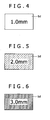
- the display device 5 numerically displays, as shown in Fig. 4 , a current stroke variation on the display 5d.
- the indication of "1.0 mm" on the display 5d shows that the variation relative to the initial stroke before the wearing member wears down is +1.0 mm.
- the stroke of the hydraulic cylinder 42 is increased by 1.0 mm by the abrasion between the contact plate 3b and the contact portion 41s that are contact parts, or the stork is 51.0 mm. The stroke does not reach the set value yet in this state.
- the background color of the display 5d changes to a darker color as shown in Fig. 5 .
- the background color of the display 5d changes so as to reduce the brightness. This change in background color of the display 5d is a preliminary alarm.
- the background color of the display 5d changes to a further darker color as shown in Fig. 6 .
- This change in background color of the display 5d is a second-stage alarm.
- the display device 5 changes the background color of the display 5d among three stages for each stroke variation (unit: mm) of the following three ranges (i), (ii), and (iii).
- the change in the background color of the display 5d from the state of Fig. 4 when the measurement value by the linear sensor 43 in the latched state reaches the set value corresponds to an alarm (alarm display). Namely, in this display mode, the alarm is displayed in the display device 5. In this display mode, also, the change in the display mode of displacement information of the latch member 41 in the display device 5 functions as the alarm.
- the stroke variation is graphically displayed.
- the stroke variation is displayed by bar chart, and the area of a colored section 5c showing the stroke variation increases as the value of the stroke variation increases as shown in Figs. 7, 8 and 9 .
- the inside of a frame 5f is not colored.
- the area of the colored section 5c increases within the frame 5f displayed on the display 5d.
- the fully colored frame 5f shows that the stroke has reached the set value B.
- the area of the colored section 5c increases, the area of a non-colored section 5t within the frame 5f decreases.
- Fig. 7 shows a screen of the display 5d when the stroke variation is +1.0 mm, or when the stroke is 51.0 mm. In this state, the stroke variation is displayed as the colored section 5c by bar chart in the display 5d.
- the change in the color of the colored section 5c from the state of Fig. 7 when the measurement value by the linear sensor 43 in the latched state reaches the set value corresponds to the alarm (alarm display). Namely, also in this display mode, the alarm is displayed on the display device 5. Further, also in this display mode, the change in the display mode of displacement information of the latch member 41 in the display device 5 functions as the alarm.
- the value corresponding to the stroke of the hydraulic cylinder 42 in the latched state is adopted as the set value to be stored in the storage device 6, and the display device 5 compares the set value with the measurement value by the linear sensor 43 in the latched state.
- a value corresponding to the stroke variation of the hydraulic cylinder 42 in the latched state or an indicated value of the display device 5 may be adopted as the set value to be stored in the storage device 6, and the display device 5 may compare this set value with a stroke variation obtained from the measurement value by the linear sensor 43.
- the displacement information of the latch member 41 is the stroke variation.
- the set value A is "2.0 mm" and the set value B is "3.0 mm". The display device compares such a set value with the "stroke variation" that is the indicated value.
- the material discharge opening 2h is blocked with the drop door 3 by closing the drop door 3 (door closing step).
- the latch mechanism 4 is operated so that the contact portion 41s supports the contact plate 3b upwardly, whereby the lowering of the drop door 3 is restricted, and the drop door 3 is put into the latched state in which the drop door 3 cannot be opened (latch step).
- the distance of linear movement of the piston rod 41b by the hydraulic cylinder 42 is measured by the linear sensor 43 (measuring step). This step is constantly repeated during the operation of the internal batch mixer 1.
- the measuring step does not have to be constantly performed. Namely, the measuring step may be performed only when needed.
- the stroke variation of the hydraulic cylinder 42 as the displacement information of the latch member 41 is displayed in the display device 5 based on the distance of linear movement of the piston rod 41b measured by the linear sensor 43 (display step).
- the display step is performed for each execution of the measuring step in a state where the drop door 3 is held in the latched state. Therefore, a current value of the stroke variation is constantly displayed in the display device 5 during the operation of the internal batch mixer 1.
- the display step may be performed only when needed.
- the display device 5 compares the measurement value of linear movement distance of the piston rod 41b in the latched state with the set value (set values A and B), and performs the alarm display when the measurement value reaches the set value (alarm step). This alarm step of performing the comparison of the measurement value with the set value and the alarm display is constantly repeated during the operation of the internal batch mixer 1.
- the stroke of the hydraulic cylinder 42 can be confirmed from an electric signal output from the linear sensor 43.
- the operator can grasp a wear status for wearing member by watching the display device 5 while operating the internal batch mixer 1 to perform the mixing operation of material.
- the operator can stop the operation of the internal batch mixer 1 as needed by monitoring the display of the display device 5.
- the operation of the internal batch mixer can be automatically stopped when the measurement value by the linear sensor 43 reaches the set value A or the set value B.
- the operator can monitor the conditions of wearing members distant from the operation site of the internal batch mixer 1 without leaving the operation site.
- the operator also can confirm the stroke of the hydraulic cylinder 42 during the mixing operation of the internal batch mixer 1 without leaving the above-mentioned operation site.
- the above-mentioned structure can dispense with, even in a case in which the wear status of wearing member cannot be viewed from the outside due to a dust collecting cover attached to the confirmation position of wearing member, the operation of detaching the dust collecting cover for confirmation of the wear status of wearing member. Further, the above-mentioned structure can remarkably improve, when the dust collecting cover is attached to the confirmation position, the work environment in the stroke confirming operation for the hydraulic cylinder 42.
- the life of consumable part can be predicted by analyzing log data for the measurement value by the linear sensor 43. Concretely, the life of consumable part can be predicted by confirming the wear status of the consumable part from the log data obtained by use of software formed for log data analysis.
- the measurement value by the linear sensor 43 can be easily stored as a log of the mixing machine 1 since the measurement value is electric signal data.
- the electric signal data of the measurement value by the linear sensor 43 facilitates display of the value of stroke variation of the hydraulic cylinder 42 or the value of stroke of the hydraulic cylinder 42 on an operation monitoring display or an operation display of a centralized control system, and recording of such a value as data.
- the contact plat 3b and the contact portion 41s that are wearing members can be easily and surely maintained.
- missing of the replacement opportunity of consumable part (wearing member) can be eliminated since the wear status of wearing member can be easily and surely confirmed, and damages on the internal batch mixer 1 can be consequently suppressed.
- scale readjustment operation after replacement of wearing member is dispensed with, differed from a conventional structure configured to confirm the wear status of wearing member by visually comparing a mark attached to a piston rod with the scale of a scale plate.
- FIG. 5 and 6 A second embodiment of the present invention will be described about differences from the above-mentioned embodiment, in reference to Figs. 5 and 6 .
- the parts denoted by 101, 101a, 102, 102h, 102j, 102s 103, 103b, 103r, 103s, 103v, 103w, 104, 104B, 141b, 142 and 107 in Figs. 5 and 6 correspond to the parts denoted by 1, 1a, 2, 2h, 2j, 2s, 3, 3b, 3r, 3s, 3v, 3w, 4, 4B, 41b, 42 and 7 in Figs. 1 and 2 respectively.
- a tip section 103v is formed on a drop door 103.
- the drop door 103 includes a metallic contact plate 103b as shown in Figs. 5 and 6 .
- the contact plate 103b is disposed so as to be the closest to a latch striker 141s, which will be described later, in a closed state of the drop door 103.
- An inclined surface 103z is formed at a lower portion of the contact plate 103b as shown in Fig. 6 .
- the inclined surface 103z is inclined so that its height from the base increases gradually toward a hydraulic cylinder 142.
- a latch mechanism 104 includes the hydraulic cylinder 142, the linear sensor 43, and a latch member 141.
- the hydraulic cylinder 142 falls into the concept of the linear actuator in the present invention.
- the hydraulic cylinder 142 includes a piston rod 141b, a piston not shown, and a cylindrical body 145.
- the piston rod 141b is inserted into the cylindrical body 145, and the piston is disposed inside the cylindrical body 145.
- the hydraulic cylinder 142 is mounted on a base 104B in an intermediate trunnion support form.
- the hydraulic cylinder 142 is mounted on the base 104B through a rotary shaft 145s extending in a direction orthogonal to the axial direction of the piston rod 141b.
- the rotary shaft 145s is fixed to the cylindrical body 145, and the rotary shaft 145s is rotatably supported by the base 104B.
- the hydraulic cylinder 142 can rotate around the rotary shaft 145s.
- the latch member 141 is a member contacting with the contact plate 103b of the drop door 103.
- the latch member 141 has a body section 141v, two flange sections 141c, and a latch striker 141s.
- the latch striker 141s is attached to an upper portion of the body section 141v to contact with the contact plate 103b.
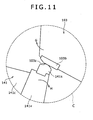
- the surface of the latch striker 141s is formed into a curved surface. Concretely, the surface of the latch striker 141s is formed so as to constitute a part of the side surface of a cylinder disposed in parallel to the axial direction of the rotary shaft 103s (refer to Fig. 11 ).
- the latch striker 141s is fixed to the body section 141v by use of a bolt not shown.
- the body section 141v is mounted on the base 104B through a rotary shaft 141d.
- the body section 141v can rotate around the rotary shaft 141d.
- the body section 141v is held between two support flanges 141j provided on the base 104B, and the rotary shaft 141d extends through the two support flanges 141j and the body section 141v.
- Fig. 10 only one support flange 141j of the two support flanges 141j is shown.
- the two flange sections 141c extend from the body section 141v toward the hydraulic cylinder 142.
- the flange sections 141c are connected to the tip portion of the piston rod 141b by a rotary shaft 141f. This allows the body section 141v and the piston rod 141b to rotate relatively around the rotary shaft 141f. Concretely, the tip portion of the piston rod 141b is held between the two flange portions 141c, and the rotary shaft 141f extends through the two flange portions 141c and the tip portion of the piston rod 141b. In Fig. 10 , only one flange portion 141c of the two flange portions 141c is shown.
- the latch mechanism 104 has a toggle structure. Namely, in the latch mechanism 104, each member is mutually fixed and connected by use of three rotary shafts (the rotary shaft 145s, the rotary shaft 141d, and the rotary shaft 141f). The axial directions of the rotary shaft 145s, rotary shaft 141d, and rotary shaft 141f are parallel to the axial direction of the rotary shaft 103s.
- the hydraulic cylinder 142 is rotatable around the rotary shaft 145s, the axial direction of the piston rod 141b or the reciprocating direction of the piston rod 141b is not settled in one fixed direction, differed from the above-mentioned first embodiment.
- the angle formed by the direction of arrow E and the horizon in the state of Fig. 10 (refer to angle ⁇ 2 in Fig. 10 ) is reduced according to the abrasion between the latch striker 141s and the contact plate 103b, the direction of arrow E representing the axial direction of the piston rod 141b.
- the axial direction of the piston rod 141b gets close to the horizontal from the state of Fig. 10 .
- the drop door 103 is held in the latched state by operating the latch mechanism 104 with the drop door 103 being closed.
- the piston rod 141b is moved toward the drop door 103 by the action of hydraulic pressure on the piston within the hydraulic cylinder 142 from the head chamber side, whereby a force in a direction of falling toward the drop door 3 (the direction of arrow H in Fig. 11 ) is given to the body section 141v, whereby the latch striker 14s advances to the lower side of the contact plate 103b.
- a force in a direction of moving upwardly from the latch striker 104s (the direction of arrow G in Fig. 11 ) is given to the contact plate 103b of the drop door 103.
- two contact surfaces 103w of the drop door 103 are pressed to an edge portion forming a material discharge opening 102h of a casing 102.
- the contact plate 103b and the latch striker 141s are consumable parts (replacement parts).
- the internal structure of the hydraulic cylinder 142, the principle of magnet position detection by the linear sensor 143, and the display in the display device 5 in this embodiment are the same as in the above-mentioned first embodiment.
- the force acting on the drop door 103 from the latch member 141 increases as the angle formed by the longitudinal direction of the body section 141v or a direction connecting the rotary shaft 141d to the latch striker 141s, and the normal at the contact point between the latch striker 141s and the contact plate 103b (angle ⁇ 1 in Fig. 1 ) gets close to 180°.
- the contact part of the casing 102 with the drop door 103, or the thinned portion at the edge forming the material discharge opening 102h of the casing 102 (the section K enclosed by the broken line in Fig. 10 ) is seriously deformed.
- such a damage on the casing 102 can be prevented by monitoring the wear statuses of the contact plate 103b and the latch striker 141s that are wearing parts.
- the piston rod 141b of the hydraulic cylinder 142 that is a linear actuator is provided as a member separate from the body section 141v (latch member 141), differed from the first embodiment.
- the embodiment of the present invention in which the latch member of the latch mechanism contacts with the door is not limited to the first and second embodiments.
- consumable parts replacement parts
- the contact plate 3b, 103b provided in the drop door 3, 103 may be omitted, and the latch member may directly contact the body section of the drop door.
- the latch striker 141s provided in the latch member may be omitted, and the drop door may directly contact with the body section of the latch member. In such a case, the whole drop door and the whole latch member are replacement parts.
- the contact portion 41s is formed integrally with the body of the piston rod in the latch member 41 of the first embodiment, the contact portion 41s may be composed of a different member separated from the body of the piston rod. In this case, the contact portion 41s and the body of the piston rod are mutually fixed by means of adhesive or screwing.
- the contact portion 41s is a latch member in this case, and the latch member is a member different from a linear actuator. In this case, the contact portion 41s is a replacement part.
- a personal computer may be arranged instead of the control panel.
- a display of the personal computer corresponds to the display device
- a hard disk in the body unit of the personal computer corresponds to the storage device.
- the central processing unit 5s of the above-mentioned display device 5 corresponds to a CPU within the personal computer.
- the display device, the storage device or the alarm device may be in a remote position distant from the mixing device.
- a latch mechanism of a type in which a slide member is provided between the latch member and the drop door as disclosed in Japanese Patent Application Laid-Open No. 9-220456 , can be also applied.
- the slide member is an intermediate member sliding along the inclination direction of inclined surfaces formed on the latch member and the drop door respectively.
- the internal batch mixer 1 includes a mixing device 1a (refer to Fig. 15 ) for mixing material, and an indicator 27 (refer to Fig. 13 ) which displays displacement information of a fixed-side seal member 10 and an alarm which will be described later.
- the mixing device 1a includes a casing 3, a pair of mixing rotors 2, 2, a rotor shaft 7 (refer to Fig. 13 ), and a dust stop device 50.
- the casing 3 is formed in a hollow shape, and stores the pair of mixing rotors 2, 2 so as to be rotatable around respective axes.
- the casing 3 includes a medium flow channel (not shown) for cooling or heating a mixed product through the casing 3.
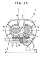
- the inner surface of the casing 3 is formed so that a vertical section thereof shows a cocoon-like shape.
- An end plate 8 is jointed to an end surface of the casing 3 in the axial direction of the mixing rotor 2 as shown in Fig. 13 , whereby a chamber 4 composed of a lateral pair of mixing chambers 4a, 4b is formed within the casing 3.
- An input port 3a for putting mixing material such as rubber or plastics into the chamber 4 is formed at the upper side center of the casing 3.
- a floating weight 5 for pushing the mixing material, which is put in the input port 3a, into the chamber 4 is provided on the input port 3a so as to be capable of rising and lowering.
- a discharge port 3b for discharging the material which has been mixed into a desired mixed state within the chamber 4 to the outside is formed at the lower side center of the chamber 4 in the casing 3.
- a drop door 6 for opening and closing the discharge port 3b is provided at a part of the casing 3 in which the discharge port 3b is formed.
- the floating weight 5 and the drop door 6 constitute a part of the inner wall surface of the chamber 4, during mixing of the material within the chamber 4, by being closely fitted to the casing 3.
- the dust stop device 50 in the internal batch mixer 1 of the explanatory example is a device for arresting the mixing material pushed and mixed in the chamber 4 from leaking out of the mixing chamber 4a as dust from an area located in the vicinity of an end portion of the mixing rotor 2 within the mixing chamber 4a.
- the dust stop device 50 includes a rotation-side seal member 9, a fixed-side seal member 10, and a pressing force imparting mechanism 29.
- the rotation-side seal member 9 is fixed to an end surface 2b of the mixing rotor 2.
- a rotor shaft 7 of the mixing rotor 2 is rotatably inserted through the fixed-side seal member 10.
- the pressing force imparting mechanism 29 biases the fixed-side seal member 10 toward the end surface 2b of the mixing rotor 2 so that the fixed-side seal member 10 is in pressure contact with the rotation-side seal member 9.
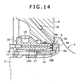
- the above-mentioned mixing rotor 2 is inserted through each of the mixing chambers 4a, 4b of the internal batch mixer 1. Both ends of each mixing rotor 2 are increased in diameter toward the rotor end surface 2b so that its rotor diameter is maximized at the rotor end surface 2b, as shown in Figs. 13 and 14 . Namely, diameter-increased portions 2a are formed respectively at both ends of each mixing rotor 2.
- the rotor shaft 7 with a shaft diameter smaller than the rotor diameter of the diameter-increased portion 2a is protruded on the inner periphery of the rotor end surface 2b.
- the ring-like rotation-side seal member 9 which can be divided into two pieces is fixed to the rotor end surface 2b.
- a circular recess is formed in the rotor end surface 2b, and the rotation-side seal member 9 is fixed to this recess.
- the rotation-side seal member 9 is composed of a seal member body 9a having an L-shaped section, and a ring-like sliding member 9b fixed to a rear end opposite to the rotor end surface 2b of the seal member body 9a.
- the sliding member 9b is attachable to and detachable from the seal member body 9a.
- the rotation-side seal member 9 is fixed to the rotor end surface 2b by being pressed by a ring-like collar 11 from the inner periphery toward the outer periphery. This pressing force is produced by fastening of a bolt 12. This allows the rotation-side seal member 9 to rotate integrally with the mixing rotor 2.
- the fixed-side seal member 10 is a ring-like member which can be divided into two pieces.
- the rotor shaft 7 is rotatably inserted to the inside of the fixed-side seal member 10. While the above-mentioned rotation-side seal member 9 is rotated together with the mixing rotor 2, the fixed-side seal member 10 is not rotated.
- the fixed-side seal member 10 is composed of a ring-like seal member body 10a and a ring-like sliding member 10b fixed to a tip thereof on the mixing rotor 2 side.
- the sliding member 10b is attachable to and detachable from the seal member body 10a.
- the seal member body 10a of the fixed-side seal member 10 is liquid-tightly fitted to the end plate 8 through a seal ring 14 at a position in the vicinity of the mixing rotor 2 so as not to leak the mixed product or lubricating oil to the outside. Further, a cooling water passage 15 is formed at the rear end portion of the seal member body 10a so as to extend in the circumferential direction. A lubricating oil passage 17 is formed in the seal member body 10a so as to extend in the axial direction. A cooling water pipe 16 is connected to the cooling water passage 15. Cooling water is caused to inflow to the cooling water passage 15 through the cooling water pipe 16, whereby the fixed-side seal member 10 is cooled. A lubricating oil pipe 18 is connected to the lubricating oil passage 17.
- the sliding member 9b of the rotation-side seal member 9 and the sliding member 10b of the fixed-side seal member 10 are formed of, for example, hard facing alloy.
- materials not impregnated with oil such as ceramics and sintered carbon, and metals impregnated with oil, such as gunmetal, cast iron and sintered metal can be given.
- a process oil passage 19 is formed in the end plate 8.
- a process oil pipe 13 for supplying process oil is connected to the process oil passage 19.
- the process oil is oil such that it never adversely affects the quality of mixed product even if entrapped into the chamber 4.
- the process oil is supplied to between the contact surfaces of the sliding member 9b and the sliding member 10b through the process oil pipe 13 and the process oil passage 19.
- mineral oils of aroma series, naphthene series and the like can be mainly used.
- a synthetic plasticizer typified by DOP (dioctyl phthalate) is used as the process oil.
- the pressing force imparting mechanism 29 includes a hydraulic cylinder 23, a linear sensor 26 attached to the hydraulic cylinder 23, and a yoke 20 to one end of which the hydraulic cylinder 23 is attached.
- the hydraulic cylinder 23 includes a cylinder body 24 and a piston rod 25 provided within the cylinder body 24 so to be movable in the axial direction of the mixing rotor 2.
- the hydraulic cylinder 23 is a linear actuator in which the piston rod 25 linearly moves in the axial direction of the mixing rotor 2 by supplying oil to a head-side chamber 23a within the cylinder body 24 or discharging oil from the head-side chamber 23a.
- the linear actuator means an actuator provided with a moving part which linearly moves.
- the piston rod 25 falls into the concept of the moving part in the present invention.
- the hydraulic cylinder 23 biases the fixed-side seal member 10 toward the rotor end surface 2b by moving the piston rod 25 toward the rotor end surface 2b in its axial direction.
- the linear actuator of the present invention is not limited to the hydraulic cylinder 23.
- the actuation source may be pressure of other liquids without being limited to the hydraulic pressure.
- a pneumatic cylinder can be used also as the linear actuator.
- a tip of the piston rod 25 is fitted to one end of a columnar rod end guide 25a.
- a spring 28 is inserted to the rod end guide 25a from the other end side.
- the rod end guide 25a is in contact with the end plate 8 through the spring 28.
- the linear sensor is a sensor for measuring travel distance by linear. movement of the linear actuator.
- the linear sensor 26 in this explanatory example is attached to the hydraulic cylinder 23, and detects displacement of the piston rod 25 in the axial direction of the mixing rotor 2. Concretely, the linear sensor 26 detects the stroke or piston position of the piston rod 25 of the hydraulic cylinder 23.
- the linear sensor 26 is attached to a head portion of the hydraulic cylinder 23.
- a magnetostrictive displacement sensor can be used as the linear sensor 26, for example.
- the magnetostrictive displacement sensor is a displacement sensor based on a magnetostrictive phenomenon by the Wiedemann effect.
- the magnetostrictive displacement sensor is configured so that an absolute position of a magnet which moves along a rod-like sensor probe in no contact to the probe is accurately detected by causing torsional distortion in a magnetostrictive wire within the probe by the magnet, and measuring the propagation time of this distortion.
- a linear sensor a wire sensor, a laser sensor or the like is also usable.
- the yoke 20 is a plate member for transmitting an actuating force of the hydraulic cylinder 23 to the fixed-side seal member 10.
- the hydraulic cylinder 23 is attached to one end of the yoke 20, and a yoke pin 21 is attached to each of the bifurcated other ends of the yoke 20.
- a yoke tack 22 is inserted at the fork of the yoke 20 or substantially at the center in the longitudinal direction of the yoke 20, whereby a yoke mechanism in which the yoke 20 oscillates with the yoke tack 22 as a support point is constituted.
- the yoke tack 22 is fixed to the end plate 8, and the yoke 20 is supported by the yoke tack 22. Tips of the two yoke pins 21 are fitted to holes formed in the end surface opposite to the mixing rotor 2 of the fixed-side seal member 10 respectively.
- the fixed-side seal member 10 is prevented from rotating by the yoke pins 21 attached respectively to the bifurcated ends of the yoke 20.
- the rotation of the fixed-side seal member 10 is further surely prevented by pressing the yoke pins 21 onto the fixed-side seal member 10 through the yoke 20 by the hydraulic cylinder 23.
- the indicator 27 is electrically connected to the linear sensor 26 through an output cable.
- the indicator 27 is provided outside the mixing device 1a.
- the indicator 27 falls into the concept of the display device in the present invention.
- the indicator 27 displays displacement information of the fixed-side seal member 10 in a state where the fixed-side seal member 10 is in pressure contact with the rotation-side seal member 9 by the pressing force imparting mechanism 29 or in a state where the piston rod 25 of the hydraulic cylinder 23 presses the fixed-side seal member 10 to the rotation-side seal member 9.
- the indicator 27 fetches an output signal from the linear sensor 26 and displays the displacement information according to the detection value by the linear sensor 26.
- the indicator 27 can perform remote display at a position distant from the pressing force imparting mechanism 29.
- the indicator 27 is incorporated to a control panel or the like set near the mixing device 1.
- An operation monitoring screen of the control panel set near the mixing device 1a or an operation terminal screen of a centralized control system set at a location distant from the mixing device 1a can be used as the display device to display the displacement information according to the detection value by the linear sensor 26.
- Fig. 13 that is a sectional view taken along XIII-XIII of Fig. 12 , the indicator 27 is not drawn as a sectional view. Fig. 13 only schematically shows that the indicator 27 is wire-connected to the linear sensor 26.
- the displacement information may be the position (detection value) itself of the piston rod 25 at the moment of pressing the fixed-side seal member 10 to the rotation-side seal member 9 by the piston rod 25 of the hydraulic cylinder 23, or the variation from initial position of the piston rod 25 at that time.
- the displacement information may be the position or variation in position (displacement) of the fixed-side seal member 10 which is obtained by converting the detection value or variation from initial position of the piston rod 25 according to the lever ratio of the yoke mechanism, or the ratio of the distance between the hydraulic cylinder 23 and the yoke tack 22 to the distance between the yoke tack 22 and the yoke pin 21.
- the displacement information can be displayed in the indicator 27 as a numerical value or as a graph corresponding to the numerical value.
- the indicator 27 doubles as an alarm device, and has alarm display function. Concretely, the indicator 27 compares the detection value by the linear sensor 26 with a preset set value, and displays an alarm when the detection value by the linear sensor 26 reaches the set value.
- the hydraulic cylinder 23 of the pressing force imparting mechanism 29 biases the fixed-side seal member 10 toward the end surface 2b of the mixing rotor 2 through the yoke 20 and the yoke pin 21, whereby the sliding member 10b of the fixed-side seal member 10 is pressed onto the sliding member 9b of the rotation-side seal member 9 at a predetermined pressing force.
- the spring 28 an end of which contacts with the end plate 8 functions to cause the yoke 20 to follow a minute movement in the axial direction of the mixing rotor 2 so as to maintain the pressure-contact state of the sliding member 10b of the fixed-side seal member 10 to the sliding member 9b.
- the upper surface of the chamber 4 is opened by separating the floating weight 5 from the casing 3 with the drop door 6 being in close contact with the casing 3 as shown in Fig. 15 .
- the floating weight 5 is closely fitted to the casing 3 to push the mixing material to the inside of the chamber 4.
- the mixing material within the chamber 4 is cooled through the casing 3, before and after this pushing, by circulating cooling water through the cooling pipe joined to the outer wall surface of the casing 3, and the fixed-side seal member 10 is also cooled by circulating cooling water through the cooling water passage 15 as shown in Fig. 14 .
- mixing of the mixing material is started by rotating the mixing rotors 2, 2 in mutually reverse directions and thereby shearing and dispersing the mixing material within the chamber 4 so that a mixed product in a desired mixed state can be obtained. Since the rotation-side seal member 9 is rotated together with the mixing rotor 2 upon rotation of each mixing rotor 2, the sliding member 9b of the rotation-side seal member 9 and the sliding member 10b of the fixed-side seal member 10 slide to each other at a speed according to the rotating speed of the mixing rotor 2. A friction force proportional to the pressing force by the hydraulic cylinder 23 is generated between the contact surfaces of both the sliding members 9b, 10b, and as a result, both the sliding members 9b, 10b are worn away with heating.
- the mixing rotor 2 When the mixing rotor 2 is rotated with both the sliding members 9b, 10b being in pressure contact with each other as described above, the mixed product is pressed onto the inner surface of the casing 3 or the end plate 8 constituting the chamber 4 (mixing chamber 4a), whereby a part of the mixed product enters into a clearance between the diameter-increased portion 2a of the mixing rotor 2 and the end plate 8 shown in Fig. 14 .
- the sliding member 10b of the fixed-side seal member 10 is in pressure contact with the sliding member 9b of the rotation-side seal member 9 at a predetermined pressing force, and the seal member body 10a of the fixed-side seal member 10 is closely fitted to the end plate 8 through the seal ring 14.
- the mixed product Since the clearance between the diameter-increased portion 2a of the mixing rotor 2 and the end plate 8 is thus in a sealed state by the pressure contact between both the sliding members 9b, 10b and the presence of the seal ring 14, the mixed product never leaks out even if it penetrates an area inside the chamber 4 from the sealed part of the clearance. As a result, the mixed product is mixed with good quality within the chamber 4.
- the dust stop for preventing the leak of dust of the mixed product is constituted by the contact surface of the rotation-side seal member 9 rotating integrally with the mixing rotor 2 and the contact surface of the fixed-side seal member 10 pressed onto this contact surface with a predetermined pressing force, and also by the seal ring 14.
- the indicator 27 then displays displacement information of the fixed-side seal member 10 according to a detection value by the linear sensor 26.
- the displacement information of the fixed-side seal member 10 according to the detection value may be, as described above, the position itself of the piston rod 25 of the hydraulic cylinder 23 at the moment of pressing the fixed-side seal member 10 (detection value), the variation from initial position of the piston rod 25, or the position or variation in position of the fixed-side seal member 10 obtained by converting the above-mentioned detection value or variation from initial position of the piston rod 25 according to the lever ratio of the yoke mechanism.
- the lever ratio of the yoke mechanism is the ratio of the distance between the hydraulic cylinder 23 and the yoke tack 22 to the distance between the yoke tack 22 and the yoke pin 21.
- the indicator 27 displays the displacement information, whereby the operator can confirm a pushed amount of the fixed-side seal member 10 to the end surface 2b of the mixing rotor 2 from its initial position, that corresponds to just the abrasion loss of both the sliding members 9b, 10b. The operator can grasp a current total thickness of the sliding members 9b, 10b from the pushed amount of the fixed-side seal member 10.
- one of the sliding member 9b and the sliding member 10b is composed of a member resistant to abrasion, and the other member is composed of a member susceptible to abrasion, compared with the one member.
- the indicator 27 compares the detection value from the linear sensor 26 with a set value which is preliminarily stored in a storage unit of the indicator 27, and gives an alarm (warning) when the detection value reaches the set value. At this time, the indicator 27 displays the alarm.
- the issuing of the alarm is never limited to the form in which the indicator 27 displays the alarm.
- an alarm device incorporated in the indicator 27 and configured to issue an alarm by a method other than display may give an alarm, or an alarm device provided separately from the indicator 27 may give an alarm by issuing warning.
- the alarm may be, besides the alarm display to be displayed on the indicator 27 or the like, an audible alarm emitted from an alarm system.
- the alarm display can be attained by displaying warning characters, by lighting an alarm lamp, by changing the display form of displacement information of the fixed-side seal member 10 displayed on the indicator 27, by changing the background color of the display screen, or the like.
- the audible alarm may be emitted by use of an oscillating circuit which generates siren sound, alarm bell sound or the like. Further, a form such that a control device which has read an output waveform of audible alarm stored in a memory causes a speaker to generate an audible alarm according to the output waveform can be adopted.
- the indicator 27 displays displacement information according to the detection value from the linear sensor 26 at the moment of pressing the fixed-side seal member 10 by the hydraulic cylinder 23, whereby the operator can easily grasp displacement of the fixed-side seal member 10 during the operation of the mixer 1.
- the indicator 27 facilitates grasp of the wear level of the sliding member 10b or the sliding member 9b that is a wearing member.
- the operator can grasp the wear level of the wearing member without leaving the working site.
- the operator can also know the coming of the replacement time (life) of the wearing member before the mixing material within the chamber 4 begins to leak to the outside through a clearance in the vicinity of the end of the mixing rotor 2 since he/she can check for the wear level of the wearing member during the operation of the internal batch mixer 1.
- the operator can prevent continuous use of the wearing member beyond its application limit by monitoring the wear level of the wearing member through the indicator 27.
- breakage of peripheral facilities resulting from the leak of the mixing material for example, breakage of peripheral piping or a temperature sensor can be prevented.
- an arithmetic device (not shown) with software for predicting the life of wearing member based on log data for the detection value by the linear sensor 26 showing abrasion data of the wearing member is incorporated to the control panel set near the mixing device 1a, the operation terminal of the centralized control system or the like, and an output signal from the linear sensor 26 is computed or analyzed by this arithmetic device, whereby the life of the sliding member 10b or the sliding member 9b that is a wearing member can be also predicted.
- the indicator 27 gives an alarm according to the coming of the replacement time or application limit of the sliding member 10b or the sliding member 9b that is a wearing member. The operator can further surely grasp the wear level of the wearing member by this alarm.
- the above-mentioned alarm device preferably can store at least two stages of the alarm set value.
- the first-stage alarm set value is used to announce that the wearing member has reached the replacement time before the application limit
- the second-stage alarm set value is used to announce that the wearing member has reached the application limit.
- a preliminary alarm can be given to announce that the wearing member has reached the replacement time for securing of a preparation period required for manufacturing or the like of the wearing member, planning of replacement work of the wearing member or the like.
- the indicator 27, preferably, doubles as the alarm device and has the function of displaying the above-mentioned alarms.
- the indicator 27 which displays displacement information of the fixed-side seal member 10 displays the above-mentioned alarms, whereby the operator can grasp the wear level of the wearing member and determine whether the wear is at the level of the replacement time or application limit of the wearing member only by monitoring the indicator 27.
- the indicator 27 is preferably configured to perform alarm display by changing the display method of the displacement information of the fixed-side seal member 10.
- the alarm display by changing the display method of the displacement information of the fixed-side seal member 10 is attained, for example, by flashing, color reversion or color change of the displacement information of the fixed-side seal member 10 displayed on the indicator 27 (numerical display, graphic display), or a combination thereof.
- the color change is overall color change or partial color change of the indication on the indicator 27.
- Such a change in the display method of displacement information by the indicator 27 allows the operator to easily and simultaneously perform the grasp of the wear level of wearing member and the determination for whether the wear is at the level of the replacement time or application limit without changing the direction of eyes.
- the internal batch mixer includes: a mixing device for mixing material; and a display device provided outside the mixing device, wherein the mixing device includes: a casing in which the material is mixed and which has a material discharge opening formed to discharge the mixed material; a door which is adapted to open and close the material discharge opening by rotating around a shaft, and to block the material discharge opening when it is in a closed state; and a latch mechanism which is adapted to hold, during mixing of the material within the casing, the door in a latched state, the latched state being a state in which the latch mechanism presses the door to the casing so that the door blocks the material discharge opening and cannot be opened, and which is adapted to release the latched state when discharging the material mixed within the casing out of the casing
- the latch mechanism includes: a latch member provided to be contactable with the door; a linear actuator which has a linearly-movable moving part and is adapted to supply power to the latch member to direct the latch member to the door
- the display device provided outside the mixing device can display, based on a measurement value by the linear sensor, latch member displacement information, or information about the stroke of the moving part of the linear actuator. Therefore, the operator can easily grasp information about wear status in a contact area between the door and the latch member from the latch member displacement information displayed in the display device during the operation of the mixer. The operator can know the replacement time of wearing member since he/she can grasp the wear status in the contact area during the operation of the mixer. The operator further can monitor the wear status in the contact area by monitoring the displacement information displayed in the display device. As a result, deformation of the edge portion forming the material discharge opening of a portion near the inner surface of the casing, the deformation resulting from continuous use of a wearing member beyond its application limit, can be prevented.
- the internal batch mixer is used to mix material such as rubber or plastics.
- the casing is a housing member having a mixing chamber formed inside. In the mixing chamber within the casing, mixing of the material is performed by mixing rotors.
- the door is a hinged door, and opens and closes in an arc around a rotary shaft.
- the linear actuator is an actuating device which converts input energy to linear movement, for example, such as a hydraulic cylinder, a pneumatic cylinder, or a ball screw mechanism.
- the distance of linear movement of the moving part of the linear actuator means a travel distance of the moving part of the linear actuator along a straight line.
- the linear actuator is the hydraulic cylinder
- the moving part is a piston
- the distance of linear movement corresponds to the travel distance of the piston.
- the latch mechanism may be of the slide type in which the latch member linearly moves, or of the toggle type in which the latch member rotationally moves.
- the moving direction of the latch member by power supply from the linear actuator may be a direction along the linear movement of the moving part of the linear actuator or any other direction.
- the latch member of the latch mechanism may be directly attached to the moving part of the linear actuator.
- the power is directly supplied from the moving part of the linear actuator to the latch member.
- a different member may be provided between the latch member of the latch mechanism and the moving part of the linear actuator to indirectly supply the power of the linear actuator to the latch member through the different member.
- the moving part of the linear actuator and the latch member may be formed as an integrated unit.
- the linear sensor is a sensor for measuring the distance of linear movement of the moving part of the linear actuator.
- a linear encoder for example, a linear encoder, a linear potentiometer or the like is applied.
- the sensor system which can be used for this linear sensor is a magnetostrictive system, a laser system, a wire system or the like.
- the linear sensor may be configured to perform digital output or analog output.
- the latch member displacement information is information about the position or variation in position of the latch member in the latch state, which directly or indirectly shows the stroke of the linear actuator. The operator can grasp the wear status in the contact area between the door and the latch member from this displacement information.
- the latch member displacement information to be displayed in the display device may be a value (measurement value) as is of linear movement distance of the moving part of the linear actuator, or a value of rotating angle of the latch member obtained by converting the value of linear movement distance of the moving part of the linear actuator when the latch mechanism is of the toggle type.
- the displacement information of the latch member may be a value showing the relative position to initial position, e.g., a value of variation in stroke relative to initial stroke of the linear actuator, or a value showing an absolute positional variation, e.g., a value of variation in stroke measurement value of the linear actuator.
- the display device may display, for example, the value of linear movement distance of the moving part of the linear actuator point by point on a real-time basis, or may display the value of rotating angle of the latch member obtained by converting the linear movement distance of the moving part of the linear actuator in the case of the toggle-type latch mechanism.
- the display device which can perform remote display at a location distant from the latch mechanism, may be an operation monitor display of a control panel set in the vicinity of the mixing device, or an operation display (operation terminal screen) of a centralized control system set in a location distant from the mixing device.
- the display device may directly display a numerical value of the latch member displacement information or may graphically display the numerical value of the latch member displacement information.
- the graphical display may be display by bar chart, circular chart, line chart or the like.
- a liquid crystal display, a cathode-ray tube, a plasma display, an LED or the like can be used as the display device.
- a consumable part such as a contact plate, that is a replacement part, may be provided at a contact portion with the latch member, or such a consumable part may be omitted.
- a consumable part such as a latch striker, that is a replacement part, may be provided at a contact portion with the door, or such a consumable part may be omitted.
- the above-mentioned internal batch mixer further includes a storage device which is adapted to store a set value relating to the displacement information of the latch member; and an alarm device which is adapted to compare the displacement information of the latch member in the latched state with the set value, and to give an alarm when the displacement information of the latch member has reached the set value.
- the alarm device when the value of latch member displacement information based on the measurement value by the linear sensor reaches an optional set value stored in the storage device, the alarm is given from the alarm device. Therefore, when the above-mentioned set value is a reference value corresponding to the replacement time or application limit of a wearing member, the alarm device gives the alarm when the wear status of the wearing member reaches the replacement time, application limit or the like, and the operator can further surely grasp the wear status of the wearing member by this alarm.
- the alarm may be an alarm display to be displayed in the display device or the like, or an audible alarm to be given from an alarm system.
- the alarm display can be attained by displaying warning characters, by lighting an alarm lamp, by changing the display mode of the latch member displacement information displayed in the display device, by changing the background color of the display screen, or the like.
- the audible alarm can be emitted by use of an oscillating circuit which generates siren sound, alarm bell sound, etc., or can be emitted by use of a speaker by reading an output waveform of audible alarm recorded on a memory.
- a RAM random access memory
- a hard disk drive or the like which is incorporated to the above-mentioned control panel or the above-mentioned centralized management system, can be used.
- the alarm device and the display device may be composed of different devices or of the same device.
- the "latch member displacement information" to be compared with the set value may be the same information as the information (display value) displayed in the display device, or information differed from the display value.
- the storage device is preferably configured so that at least two stages of the set value can be stored for the one linear sensor
- the alarm device stores two or more stages of set values as the reference value corresponding to the measurement value of linear movement distance of the moving part of the linear actuator which is measured by the linear sensor in the latched state, whereby the alarm device can give stepwise alarms for the wear status of wearing member.
- This structure allows the alarm device, for example, to give a preliminary alarm for the replacement time of wearing member and an alarm announcing the wear limit (application limit) of wearing member. In this case, securement of a preparation period for consumable parts, work planning, or the like can be efficiently performed based on this preliminary alarm, while the use of the wearing member beyond its application limit can be prevented based on the alarm announcing the wear limit to protect machine parts.
- the display device may double as the alarm device and have a function to display the above alarm
- the operator since the alarms are displayed in the display device which displays the latch member displacement information, the operator can visually recognize the alarms. Therefore, the operator can easily grasp the wear status of wearing member and determine for whether the wear status is at the level of the replacement time or application limit of wearing member.
- the display device may be configured so as to perform the display of the alarm by changing a display mode of the displacement information of the latch member
- the grasp of the wear status of wearing member and the determination for whether the wear status is at the level of the replacement time or application limit of wearing member can be easily and simultaneously performed.
- the "change in display mode of the latch member displacement information” may be “flashing”, “reversal or change of display color such as character color or background color”, “overall or partial color change in display” or the like of the latch member displacement information composed of a numerical value or graph on the screen of the display device.
Description
- The present invention relates to an internal batch mixer.
- An example of a conventional internal batch mixer according to the preamble of
claim 1 is disclosed in the followingPatent Literature 1. In an internal batch mixer ofPatent Literature 1, a mixing chamber is formed inside a casing, and mixing rotors are disposed within the mixing chamber. The casing includes a discharge opening formed to extend in the axial direction of the mixing rotor, and a drop door provided to open and close the discharge opening. The drop door prevents outflow of a material by blocking the discharge opening during mixing of the material within the mixing chamber. When the material mixed in the mixing chamber is discharged, the drop door is rotated and opened downwardly. - This internal batch mixer further includes a latch device that is a lock mechanism for the drop door. The latch device includes a latch and a hydraulic cylinder. The latch is installed to move forward and backward so as to slide relative to the drop door. The drop door is locked by pressing a contact surface of the latch onto a contact surface of the drop door by the hydraulic cylinder, and the airtightness within the mixing chamber is consequently maintained. When the latch is retracted, the drop door becomes openable.
- In a conventional apparatus as described above, repetitive opening and closing operation of the drop door causes wear at a contact area between the drop door and the latch. For example, the wear is caused on a contact plate of the door on the door side and on a latch striker of the latch on the latch side. Therefore, in the past, a wear status for contact parts (consumable parts) has been visually confirmed by dispatching a worker to a place where the latch device can be viewed.
- The conventional visual confirmation of wear status for the contact parts has been performed also by installing a scale plate on a base part of the mixer, attaching a landmark member to a piston rod of the hydraulic cylinder, and comparing a position of the landmark member with a scale of the scale plate.
- Accordingly, confirmation of wear status for a component or as-needed replacement of the component requires the reading operation of the scale or the position readjustment operation of the scale plate.
- However, since the hydraulic cylinder is generally in a location distant from the work area of a mixer's operator during mixing operation, it is troublesome for the operator to perform the above-mentioned confirmation during the mixing operation. Further, since the scale plate is generally covered with a dust collecting cover or the like, the confirmation operation or the readjustment operation is not easy. The dust collecting cover may be provided with a switch of a safety device. In this case, it is difficult to perform the above-mentioned confirmation operation during the operation of the mixer since the mixer is shut down when the dust collecting cover is opened during the operation.
- Even if the above-mentioned confirmation operation or readjustment operation is possible from the viewpoint of machine structure, the confirmation operation is difficult just the same since the scale plate is contaminated in a work environment which needs dust collection. Therefore, it is common to perform the above-mentioned confirmation operation while the operation of the mixer is stopped.
- The confirmation of the wear status, or the confirmation of the scale plate or the like, can be delayed depending on the operation cycle of the mixer. If the wear of the contact part is left in the meantime, damage on machine components such as deformation of a thin portion at the edge of the discharge opening, that is to contact with the drop door in the casing, is caused when the latch mechanism is, for example, of toggle type. When the latch mechanism is of slide type, also, the wear is similarly caused in the contact area between the door and the latch. If the replacement time of contact part is missed, the casing or the like that is a durable component is also damaged. Since it is generally difficult to continuously grasp the wear status with respect to such a contact part in the latch mechanism, the replacement time thereof can be hardly predicted. In this way, neglect of the wear status in the contact area causes damages on machine components in both the toggle type and the slide type of latch mechanisms.
- As described above, in the latch device of the conventional internal batch mixer, it is difficult to grasp the wear status of mutual contact portions of the door and the latch member, which are wearing members.
- Furthermore,
Patent Literature 5 discloses a clutch wear amount display device having the purpose of informing an operator of a clutch wear amount. - The following
Patent Literature 2 discloses an internal batch mixer provided with a seal mechanism. The seal mechanism prevents mixing material within a mixing chamber from leaking out of the mixing chamber from an area in the vicinity of an end portion of a mixing rotor within the mixing chamber. - This seal mechanism includes a seal member which prevents the leak of mixing material out of the mixing chamber by being pressed onto the end portion of the rotor in the axial direction of the rotor. The seal member is composed of a rotation-side seal member fixed to an end surface of the rotor, and a fixed-side seal member fixed to an end surface of a dust stop ring through which the rotor shaft is inserted. These rotation-side seal member and fixed-side seal member are consumable members which are worn away through mutual sliding. In
Patent Literature 2, one of these seal members is formed by use of a material consisting of a resin compound filled with graphite or short carbon fiber not more than 1/2 inch in fiber length. This allows a reduced value of friction coefficient of the sliding surfaces of both the seal members to suppress the heat generation or wear of both the seal members that are consumable members. - One of techniques relating to the seal mechanism for internal batch mixer is described in the following
Patent Literature 3. In the technique described inPatent Literature 3, the heat generation or wear of the seal members is suppressed by rotating a first sleeve having a frictional wearing member fixed to an end surface thereof, which corresponds to the above-mentioned fixed-side seal member, in a rotor rotating direction at a rotating speed lower than the rotating speed of the rotor shaft, thereby reducing the mutual sliding speed of the seal members. - Another technique relating to the seal mechanism is also described in the following
Patent Literature 4. In the technique described inPatent Literature 4, internal pressure of the mixing chamber is measured, and seal pressure, or biasing force of a seal ring to a collar ring, is appropriately adjusted in response to the measured value of pressure by an adjustment means having a hydraulic cylinder. When the mixing chamber is low in internal pressure at the terminal stage of mixing process or the like, the life of the seal members can be extended by reducing the seal pressure. - Each of the techniques descried in
Patent Literatures 2 to 4 is intended to extend the life of seal members that are consumable members by preventing the wear of the seal members. However, these seal members are consistently consumable members. Therefore, these seal members wear down little by little, and reach the end of their lives at some stage. In other words, the seal members are members which reach their application limits at some stage. On the other hand, the operator hardly confirm sliding seal portions of the seal members during the mixing operation of the mixer since the position of the seal members is distant from the operator's work area during the operation. For grasping the abrasion loss of the seal members, further, the operator must confirm a depth of wear as small as several mm. Moreover, it is difficult to confirm the abrasion loss of the seal members based on a machined part around the seal members since machined parts are fewer around the seal members in the mixer. Even if the abrasion loss of the seal portion is to be measured based on the machined part, it is substantially impossible to carry out this measurement during mixing operation. From these reasons, it often happens that a countermeasure such as replacement of seal member is taken once after dust of the mixing material begins to leak through the seal portion. - When the dust of the mixing material begins to leak through the seal portion, breakage of piping or a temperature sensor in the vicinity of the leaked mixing material is also feared in addition to damages on counter members of the mutually-sliding sliding surfaces. The breakage of the piping or temperature sensor results in further serious damage. Further, the leak of mixing material requires disposal of the leaked mixing material. A high leakage rate of the mixing material leads to deterioration of work efficiency due to the necessity of cleaning of the periphery of the mixer.
- As described above, a technique for grasping the wear level of a seal member that is a wearing member in the conventional seal mechanism for internal batch mixer was needed.
-
- Patent Literature 1: Japanese Patent Application Laid-Open No.
9-220456 - Patent Literature 2: Japanese Patent No.
3620944 - Patent Literature 3: Japanese Patent Application Laid-Open No.
10-151333 - Patent Literature 4: Japanese Utility Model Application Laid-Open No.
6-32010 - Patent Literature 5: Japanese Patent Application Laid-Open No.
61-244926 - An object of the present invention is to provide an internal batch mixer capable of solving the above-mentioned problems.
- The other object of the present invention is to provide an internal batch mixer, which facilitates grasp of wear level of a wearing member (consumable member) even during the operation of the internal batch mixer.
- According to the present invention, the above object is solved with an internal batch mixer having the features of
claim 1. -
-
Fig. 1 is a front schematic view showing an overall structure of an internal batch mixer according to a first embodiment of the present invention; -
Fig. 2 is an enlarged schematic view of section B inFig. 1 ; -
Fig. 3 is a perspective schematic view for illustrating the operating principle of a linear sensor; -
Fig. 4 is a schematic view showing a first display mode in a display device: -
Fig. 5 is a schematic view showing the first display mode in the display device; -
Fig. 6 is a schematic view showing the first display mode in the display device; -
Fig. 7 is a schematic view showing a second display mode in the display device; -
Fig. 8 is a schematic view showing the second display mode in the display device; -
Fig. 9 is a schematic view showing the second display mode in the display device; -
Fig. 10 is a front schematic view showing an overall structure of an internal batch mixer according to a second embodiment of the present invention; -
Fig. 11 is an enlarged schematic view of section C inFig. 10 ; -
Fig. 12 is a front view of a dust stop device part in an internal batch mixer according to an explanatory example; -
Fig. 13 is a sectional view taken along XIII-XIII ofFig. 12 ; -
Fig. 14 is a detailed view of section J inFig. 13 ; and -
Fig. 15 is a sectional view of the internal batch mixer according to the explanatory example. - Hereinafter, a first embodiment of the present invention will be described with reference to
Figs. 1 to 9 . - Firstly, an overall structure of an
internal batch mixer 1 according to the first embodiment of the invention will be described with reference toFig. 1 . - The
internal batch mixer 1 includes: a mixingdevice 1a for mixing material; adisplay device 5 for displaying displacement information of alatch member 41 and alarm (warning information) which will be described later; and astorage device 6 for storing a set value which will be described later. - The
mixing device 1a includes acasing 2, tworotors 2r, adrop door 3, alatch mechanism 4, and asupport base 7. Theinternal batch mixer 1 according to this embodiment is a two-shaft batch mixer, and is used, for example, for mixing of rubber raw material. - The material to be mixed is supplied into the
casing 2 through amaterial feed opening 2j, which is formed in an upper portion of thecasing 2, by a floating weight (not shown) provided within a hopper (not shown) so as to be capable of rising and lowering. The tworotors 2r formed of a metallic material are disposed within thecasing 2. The tworotors 2r are mixing rotors, which are rotated in mutually different directions by receiving a power from a motor not shown (refer to the directions of arrows inFig. 1 ). The material is mixed within thecasing 2 by this rotation of the tworotors 2r. - The mixed material is discharged through a
material discharge opening 2h formed in a lower portion of thecasing 2. When the material is discharged, thematerial discharge opening 2h is opened by thedrop door 3 rotating downward to a discharge position shown by the broken line inFig. 1 , whereby the material can be discharged out of thecasing 2. - During the mixing operation, the
drop door 3 is put into a latched state by the function of thelatch mechanism 4. In the latched state, thedrop door 3 blocks thematerial discharge opening 2h and cannot be opened. When the material is discharged, the latch mechanism releases the latched state, whereby thedrop door 3 becomes openable. - The
internal batch mixer 1 of this embodiment is configured so that display of displacement information of the latch member 41 (to be described later) and alarm display can be performed by thedisplay device 5. Hereinafter, each component will be described in detail. - The
casing 2, that is a body part of theinternal batch mixer 1, is composed of a metallic material. Thecasing 2 is supported by thesupport base 7 made of metal. Two mixingchambers 2s are formed inside thecasing 2. Each of the mixingchambers 2s is formed in a substantially columnar shape, and laterally juxtaposed as shown inFig. 1 while extending in parallel to each other. Eachrotor 2r is disposed within each mixingchamber 2s so as to extend in the same direction as the mixingchamber 2s. As described above, thematerial feed opening 2j for supplying the material to be mixed is formed at an upper portion of thecasing 2. Thematerial discharge opening 2h for discharging the material which has been mixed is formed at a lower portion of thecasing 2. Thematerial discharge opening 2h is formed to extend along the axial direction of therotor 2r. In thecasing 2, thematerial feed opening 2j, the two mixingchambers 2s and thematerial discharge opening 2h communicate with each other. - The
drop door 3 is formed of a metallic material, and functions as a lid member for blocking thematerial discharge opening 2h of thecasing 2. Thisdrop door 3 falls into the concept of the door in the present invention. Thedrop door 3 is provided to be rotatable around arotary shaft 3s. Concretely, therotary shaft 3s is fixed to thedrop door 3. Therotary shaft 3s is supported by thesupport base 7 in a rotatable state. The axial direction of therotary shaft 3s is parallel to the axial direction of therotor 2r. Thedrop door 3 opens and closes thematerial discharge opening 2h by rotating around therotary shaft 3s, and blocks thematerial discharge opening 2h when it is in a closed state. Therotary shaft 3s falls into the concept of the shaft in the present invention. - The
drop door 3 includes atip section 3v and a projectingportion 3t. Thetip section 3v is provided to protrude to the inside of thecasing 2 in a state where thedrop door 3 blocks thematerial discharge opening 2h. Thetip section 3v is formed to extend along the axial direction of therotor 2r. In a closed state of thedrop door 3, or in a state in which thedrop door 3 blocks thematerial discharge opening 2h, thetip section 3v enters to the inside of thematerial discharge opening 2h. In this state, twosurfaces 3r facing the tworotors 2r of thetip section 3v, or thesurfaces 3r at both lateral sides of thetip section 3v inFig. 1 constitute the wall surface of the two mixingchambers 2s together with the inner surface of thecasing 2. - In the
drop door 3, twocontact surfaces 3w are formed below the twosurfaces 3r. The twocontact surfaces 3w contact with the inner wall surface of thematerial discharge opening 2h in the closed state of thedrop door 3. - The projecting
portion 3t is a part to contact with acontact portion 41s (latch member 41) provided on apiston rod 41b which will be described later. This projectingportion 3t is formed to protrude toward thecontact portion 41s in the closed state of thedrop door 3. - The projecting
portion 3t includes, as shown inFigs. 1 and2 , ametallic contact plate 3b. Thecontact plate 3b of the projectingportion 3t contacts with thecontact portion 41s. Thecontact plate 3b is disposed at the tip of the projectingportion 3t or at a part closest to thecontact portion 41s of the projectingportion 3t. The surface of thecontact plate 3b is formed in a curved shape, concretely, as a part of a spherical surface. Thecontact plate 3b is fixed to the body of the projectingportion 3t by use of a bolt not shown. Namely, thecontact plate 3b is attachable and detachable. Thecontact plate 3b may be made of synthetic resin. Otherwise, thecontact plate 3b may be omitted. - A
latch mechanism 4 holds, during mixing operation, thedrop door 3 in a latched state, that is, a state in which thelatch member 41 presses thedrop door 3 onto thecasing 2 so that thedrop door 3 blocks thematerial discharge opening 2h and cannot be opened. On the other hand, thelatch mechanism 4 releases the latched state of thedrop door 3 when the material mixed within thecasing 2 is discharged out of thecasing 2. - The
latch mechanism 4 includes thelatch member 41, ahydraulic cylinder 42, and alinear sensor 43. Thehydraulic cylinder 42 falls into the concept of the linear actuator in the present invention. Thishydraulic cylinder 42 includes apiston rod 41b, apiston 41p and acylindrical body 45. Thepiston rod 41b is inserted into thecylindrical body 45. Thepiston 41p is set inside thecylindrical body 45. - The
cylindrical body 45 functions as a support for the wholehydraulic cylinder 42 and also guides thepiston 41p and thepiston rod 41b along the axial direction thereof. Thecylindrical body 45 is fixed to abase 4B. Thebase 4B is formed integrally with thesupport base 7. Namely, thehydraulic cylinder 42 is positionally fixed so as not to move relative to the position of thecasing 2. Thehydraulic cylinder 42 and thesupport base 7 only need to be set on the same base, and thebase 4B and thesupport base 7 may be composed of separated different members. - The
piston rod 41b is a bar-like member. Thepiston 41p is attached to thepiston rod 41b inside thecylindrical body 45. Thepiston 41p and thepiston rod 41b fall into the concept of the moving part in the present invention. Thepiston 41p is formed in an annular shape, and fixed while being fitted onto thepiston rod 41b. Thepiston 41p and thepiston rod 41b are mutually attachable and detachable. Thepiston rod 41b and thepiston 41p may be formed as an integrated unit. - The
latch member 41 is provided to be contactable with thecontact plate 3b of thedrop door 3. In this embodiment, thelatch member 41 corresponds to a tip section of thepiston rod 41b, or thecontact portion 41s provided integrally at an end close to thedrop door 3 of thepiston rod 41b (refer toFigs. 1 and2 ). Thecontact portion 41s is protruded in a tapered shape along the axial direction of thepiston rod 41b. In thecontact portion 41s, the diameter of a section vertical to axial direction D is reduced toward the end close to thedrop door 3. The side surface of thecontact portion 41s is formed in a conical shape, and the surface of the tip of thecontact portion 41s is formed as a curved surface constituting a part of a spherical surface. Aninclined portion 41z is formed on the upper surface of thecontact portion 41s. Theinclined portion 41z is inclined so that the distance from a center line along the axial direction D (refer to the dashed line J ofFig. 2 ) is reduced toward the tip surface of thecontact portion 41s. - The
piston rod 41b is a replacement part. If thecontact portion 41s wears down by contact with thecontact plate 3b, only thepiston rod 41b can be replaced by a new part. The latch member may be a member provided separately from the linear actuator as in a second embodiment which will be described later. - The
hydraulic cylinder 42 supplies power to thecontact portion 41s to direct thecontact portion 41s to thedrop door 3 by moving thepiston 41b and thepiston rod 41b toward thedrop door 3 with use of hydraulic pressure. Concretely, a hydraulic circuit not shown is connected to thehydraulic cylinder 42. Hydraulic oil is supplied from the hydraulic circuit to hydraulic chambers formed on both sides across thepiston 41b within thehydraulic cylinder 42. When thedrop door 3 is put into the latched state by moving the latch member 41 (contact portion 41s) toward thedrop door 3, the hydraulic oil is supplied to the hydraulic chamber (head-side chamber) on the left side of thepiston 41p inFig. 1 . When the latched state is released, the hydraulic oil is supplied to the hydraulic chamber (rod-side chamber) on the right side of thepiston 41p inFig. 1 . Thepiston rod 41b and thepiston 41p reciprocate along the axial direction of thepiston rod 41b (the direction of arrow D inFig. 1 ). Namely, thepiston rod 41b and thepiston 41b linearly move in the approaching and separating directions relative to thedrop door 3. - A
permanent magnet 41m is attached to an end on the inner side of thehydraulic cylinder 42 of thepiston rod 41b, or an end located oppositely to thedrop door 3 of thepiston rod 41b. Thepermanent magnet 41m may be attached not to thepiston rod 41b but to thepiston 41p. - A magnetostrictive wire (sensor probe) 44 is disposed inside the
hydraulic cylinder 42. Themagnetostrictive wire 44 is positionally fixed relative to thecylindrical body 45 of thehydraulic cylinder 42. Themagnetostrictive wire 44 extends along the axial direction D of thepiston rod 41b. A guide hole is formed at the center of thepiston rod 41b to extend along the axial direction D. Themagnetostrictive wire 44 is inserted into this guide hole. The stroke operation of thepiston rod 41b is performed in this state. Namely, the position of thepermanent magnet 41m is changed relative to the positionally-fixedmagnetostrictive wire 44 during the stroke movement of thepiston 41b of thehydraulic cylinder 42. Themagnetostrictive wire 44 is a metallic wire composed of nickel alloy. As the material of the magnetostrictive wire, any metallic material (ferromagnetic material) which can develop the Wiedemann effect may be adopted. For example, themagnetostrictive wire 44 may be composed of an alloy containing iron, cobalt, gadolinium, or the like. - The
linear sensor 43 measures distance of linear movement of thepiston rod 41b by thehydraulic cylinder 42, in other words, distance of linear movement along the axial direction D of thepiston rod 41b. The distance of linear movement of thepiston rod 41b with thedrop door 3 being in the latched state, or a maximum value of linear movement distance of thepiston rod 41b corresponds to the stroke of thehydraulic cylinder 42. This stroke of thehydraulic cylinder 42 is the travel distance of thepiston 41b from one end to the other end of thecylindrical body 45 in the closed state of thedrop door 3. In other words, the "stroke" of thehydraulic cylinder 42 is, when explained withFig. 1 , the travel distance of thepiston rod 41b from the left end (one end) to the right end (the other end: the position in the latched state). - The
linear sensor 43 is electrically connected to themagnetostrictive wire 44. Thelinear sensor 43 is integrally attached to a head-side end of thehydraulic cylinder 42, or an end opposite to thedrop door 3 of thecylindrical body 45 of thehydraulic cylinder 42. The integral attachment of thelinear sensor 43 to thecylindrical body 45 of thehydraulic cylinder 42 eliminates the risk of displacement of thelinear sensor 43 during the operation of the mixer. - Next, the principle of the above-mentioned measurement of linear movement distance by the
linear sensor 43 will be described with reference toFig. 3 . - Current (current pulse) is flown through the
magnetostrictive wire 44. This current flows in the direction of arrow A from the start end side of the magnetostrictive wire 44 (linear sensor 43 side). At this time, a magnetic field is produced in themagnetostrictive wire 44 along the circumferential direction. - The
permanent magnet 41m of thepiston rod 41b has a positional relation with themagnetostrictive wire 44 as shown inFig. 3 . In the vicinity of thepermanent magnet 41m, a magnetic field is produced along the axial direction D. When thepermanent magnet 41m gets close to themagnetostrictive wire 44, an oblique magnetic field as shown by the dotted line is produced, around a position near thepermanent magnet 41m of themagnetostrictive wire 44, by the composition of the magnetic field along the circumferential direction and the magnetic field along the axial direction D. This oblique magnetic field causes torsional distortion at a part near thepermanent magnet 41m of themagnetostrictive wire 44. This phenomenon is called the Wiedemann effect. The above-mentioned torsional distortion propagates on themagnetostrictive wire 44 composed of metal as ultrasonic oscillation or sonic signal. Thelinear sensor 43 specifies the position of thepermanent magnet 41m by measuring the propagation time of this ultrasonic wave or sonic wave. - An output signal from the
linear sensor 43 or a signal showing a position of thepermanent magnet 41m is input to a counter (not shown) through an A/D converter (not shown). This signal is processed by the counter, whereby a numerical value representing the distance of linear movement of thepiston 41p in thehydraulic cylinder 42 is derived. Output current from thelinear sensor 43 is 4 to 20 mA. Thelinear sensor 43 may be connected to a programmable controller, a microprocessor, etc. through the A/D converter. In this case, thepiston rod 41b can be decelerated and stopped at an optional position. - The
display device 5, that is a liquid crystal display, is provided on a control panel (not shown) disposed at a position near and outside themixing device 1a. Thedisplay device 5 includes adisplay 5d that is a display screen. Various pieces of information are displayed on thisdisplay 5d. - The
display device 5 displays a variation in stroke of thehydraulic cylinder 42 as displacement information of thelatch member 41, as shown inFigs. 4 to 9 , based on the distance of linear movement measured by thelinear sensor 43. Thedisplay device 5 functions also as an alarm device as described later. The display device and the alarm device may be constituted as different devices. - The
display device 5 includes a central processing unit (CPU) 5s. Thecentral processing unit 5s has a controller and an arithmetic device, and is electrically connected to thestorage device 6 and thelinear sensor 43. Thecentral processing unit 5s performs arithmetic processing to compare displacement information of thelatch member 41 with a set value stored in thestorage device 6. Concretely, thecentral processing unit 5s performs arithmetic processing to compare a measurement value by thelinear sensor 43 in a state in which thedrop door 3 is held in the latched state by thelatch mechanism 4, or the stroke of thehydraulic cylinder 42, with the set value stored in thestorage device 6. Thecentral processing unit 5s performs control processing to instruct thedisplay 5d to perform an alarm display when the measurement value by thelinear sensor 43 reaches the set value. - The
storage device 6, that is a RAM (Random Access Memory), is provided within the above-mentioned control panel. Thestorage device 6 preliminarily stores a plurality of set values regarding the displacement information of thelatch member 41. The "set value" means a value which is set as a value corresponding to the stroke of thehydraulic cylinder 42 or the maximum value of linear movement distance of thepiston rod 41b, and used as a reference value for alarm display which will be described later. - The
storage device 6 is configured so that a plurality of stages of the set value can be set. Namely, thestorage device 6 can store a plurality of stroke values as the set value. With respect to input of the set value to thestorage device 6, the operator can input an optional set value by use of a keyboard provided on the control panel, or a maker-recommended set value can be preliminarily stored in thestorage device 6. Thestorage device 6 may store only one set value. - The
storage device 6 further stores wear status monitoring software. This software (program) causes theinternal batch mixer 1 to execute a measuring step, a display step and an alarm step. - Next, the latched state will be described. The latched state means a state in which the
drop door 3 is locked by thelatch mechanism 4 so as not to be opened while blocking thematerial discharge opening 2h of thecasing 2. - The
piston rod 41b is initially housed inside thecylindrical body 45 by being located closer to the left end within thecylindrical body 45, and thecontact portion 41s is not protruded out of thecylindrical body 45. In this state, thedrop door 3 can freely rotate around therotary shaft 3s without contact to thecontact portion 41s. - When the
drop door 3 is rotated upwardly from a discharge position to insert thetip section 3v into thematerial discharge opening 2h, thedrop door 3 is put into a closed state, and thematerial discharge opening 2h is blocked by thedrop door 3. - The
latch mechanism 4 is operated with thedrop door 3 being closed, whereby thedrop door 3 is held in the latched state. Concretely, hydraulic pressure on the head chamber side acts on thepiston 41p of thehydraulic cylinder 42 at this time, whereby force directed to the drop door 3 (the direction of arrow D1 inFig. 2 ) is given thepiston 41p and thepiston rod 41b. Along with this, force directed to thedrop door 3 is also given to thecontact portion 41s. Theinclined portion 41z provided above thecontact portion 41s contacts with thecontact plate 3b of thedrop door 3 as shown inFigs. 1 and2 . In this state, the force directed to thedrop door 3 of thecontact portion 41s acts on thecontact plate 3b. - The
contact portion 41s advances to the lower side of thecontact plate 3b. At this time, force in an uplifting direction (the direction of arrow G inFig. 2 ) is given from theinclined portion 41z of thecontact portion 41s to the projectingportion 3t of thedrop door 3. As a result, twocontact surfaces 3w of thedrop door 3 are pressed onto the inner wall surface of thematerial discharge opening 2h (refer toFig. 1 ). Thedrop door 3 is supported upwardly by thecontact portion 41s so as not to be opened. - As described above, in the latched state, the
drop door 3 is latched by thelatch mechanism 4, and thedrop door 3 is locked so as not to be opened while blocking thematerial discharge opening 2h, whereby the air-tightness of the mixingchamber 2s is maintained. - In this embodiment, the
contact plate 3b is provided at the part of thedrop door 3, which contacts with thecontact portion 41s, as described above. Thecontact plate 3b and thepiston rod 41b provided with thecontact portion 41s are consumable parts and also replacement parts. Namely, thecontact plate 3b and thecontact portion 41s contact with each other and wear down with repeated opening and closing operations of thedrop door 3. In other words, thecontact plate 3b and thepiston rod 41b provided with thecontact portion 41s are wearing members. - The
display device 5 functions also as an alarm device which gives an alarm. Hereinafter, the display of displacement information of thelatch member 41 and alarm display by thedisplay device 5 will be described. Thestorage device 6 stores two set values as a reference value for the stroke of thehydraulic cylinder 42 or for the maximum value of linear movement distance of thepiston rod 41b. Concretely, the set values are set for two stages of "52.0 mm" (set value A) and "53.0 mm" (set value B). These two stages of set values are set relative to onelinear sensor 43. - The set value A is a reference value for replacement time of wearing member, which is recommended by a maker. Replacement of wearing member is performed when the value of stroke of the
hydraulic cylinder 42 reaches the set value A, whereby theinternal batch mixer 1 can be further surely and safely operated. The set value B is a reference value representing an application limit of wearing member. If the operation of theinternal batch mixer 1 is stopped when the value of stroke of thehydraulic cylinder 42 reaches the set value B, theinternal batch mixer 1 can be prevented from being seriously damaged. The value and setting method for the set value are not limited to those described above. - For example, if the stroke of the
hydraulic cylinder 42 is 50 mm before occurrence of wear in a wearing member, or in use of a new wearing member, stroke variation is a variation in stroke of thehydraulic cylinder 42 from this numeral value. Thedisplay device 5 can display the stroke variation (displacement information of the latch member 41) in a plurality of display modes shown below. The display mode of the stroke variation by thedisplay device 5 can be changed by operation on the control panel. - In a first display mode, the
display device 5 numerically displays, as shown inFig. 4 , a current stroke variation on thedisplay 5d. The indication of "1.0 mm" on thedisplay 5d shows that the variation relative to the initial stroke before the wearing member wears down is +1.0 mm. Namely, in this state, the stroke of thehydraulic cylinder 42 is increased by 1.0 mm by the abrasion between thecontact plate 3b and thecontact portion 41s that are contact parts, or the stork is 51.0 mm. The stroke does not reach the set value yet in this state. - When the stroke variation reaches +2.0 mm, or when the stroke reaches 52.0 mm (set value A), the background color of the
display 5d changes to a darker color as shown inFig. 5 . In other words, the background color of thedisplay 5d changes so as to reduce the brightness. This change in background color of thedisplay 5d is a preliminary alarm. - When the stroke variation reaches +3.0 mm, or when the stroke reaches 53.0 mm (set value B), the background color of the
display 5d changes to a further darker color as shown inFig. 6 . This change in background color of thedisplay 5d is a second-stage alarm. - As described above, the
display device 5 changes the background color of thedisplay 5d among three stages for each stroke variation (unit: mm) of the following three ranges (i), (ii), and (iii). - (i) 0.0 to +1.9
- (ii) +2.0 to +2.9
- (iii) +3.0 or more
- In this first display mode, "the change in the background color of the
display 5d from the state ofFig. 4 when the measurement value by thelinear sensor 43 in the latched state reaches the set value" corresponds to an alarm (alarm display). Namely, in this display mode, the alarm is displayed in thedisplay device 5. In this display mode, also, the change in the display mode of displacement information of thelatch member 41 in thedisplay device 5 functions as the alarm. - Next, a second display mode is described. In this second display mode, the stroke variation is graphically displayed. Concretely, the stroke variation is displayed by bar chart, and the area of a
colored section 5c showing the stroke variation increases as the value of the stroke variation increases as shown inFigs. 7, 8 and 9 . At an initial point of time before occurrence of wear on the wearing member, or when the stroke variation is 0, the inside of aframe 5f is not colored. The area of thecolored section 5c increases within theframe 5f displayed on thedisplay 5d. The fullycolored frame 5f shows that the stroke has reached the set value B. As the area of thecolored section 5c increases, the area of anon-colored section 5t within theframe 5f decreases. -
Fig. 7 shows a screen of thedisplay 5d when the stroke variation is +1.0 mm, or when the stroke is 51.0 mm. In this state, the stroke variation is displayed as thecolored section 5c by bar chart in thedisplay 5d. - When the stroke variation reaches +2.0 mm, or when the stroke reaches 52.0 mm (set value A), the right end position of the
colored section 5c reaches a position indicating 2.0 mm. In this state, the color of thecolored section 5c changes to a darker color as shown inFig. 8 . In other words, the color of thecolored section 5c changes so as to reduce the brightness. This change in color of thecolored section 5c is a preliminary alarm. - When the stroke variation reaches +3.0 mm, or when the stroke reaches 53.0 mm (set value B), the color of the
colored section 5c changes to a further darker color as shown inFig. 9 . This change in color of thecolored section 5c is a second-stage alarm. In this state, the inside of theframe 5f is entirely composed of thecolored section 5c. - Also in this second display mode, "the change in the color of the
colored section 5c from the state ofFig. 7 when the measurement value by thelinear sensor 43 in the latched state reaches the set value" corresponds to the alarm (alarm display). Namely, also in this display mode, the alarm is displayed on thedisplay device 5. Further, also in this display mode, the change in the display mode of displacement information of thelatch member 41 in thedisplay device 5 functions as the alarm. - In this embodiment, the value corresponding to the stroke of the
hydraulic cylinder 42 in the latched state is adopted as the set value to be stored in thestorage device 6, and thedisplay device 5 compares the set value with the measurement value by thelinear sensor 43 in the latched state. Without being limited to such a form, however, a value corresponding to the stroke variation of thehydraulic cylinder 42 in the latched state or an indicated value of thedisplay device 5, for example, may be adopted as the set value to be stored in thestorage device 6, and thedisplay device 5 may compare this set value with a stroke variation obtained from the measurement value by thelinear sensor 43. In this case, the displacement information of thelatch member 41 is the stroke variation. When explained with the above-mentioned example, the set value A is "2.0 mm" and the set value B is "3.0 mm". The display device compares such a set value with the "stroke variation" that is the indicated value. - The monitoring method of the internal batch mixer according to this embodiment will be then described.
- The
material discharge opening 2h is blocked with thedrop door 3 by closing the drop door 3 (door closing step). Thelatch mechanism 4 is operated so that thecontact portion 41s supports thecontact plate 3b upwardly, whereby the lowering of thedrop door 3 is restricted, and thedrop door 3 is put into the latched state in which thedrop door 3 cannot be opened (latch step). - The distance of linear movement of the
piston rod 41b by thehydraulic cylinder 42 is measured by the linear sensor 43 (measuring step). This step is constantly repeated during the operation of theinternal batch mixer 1. The measuring step does not have to be constantly performed. Namely, the measuring step may be performed only when needed. - Next, the stroke variation of the
hydraulic cylinder 42 as the displacement information of thelatch member 41 is displayed in thedisplay device 5 based on the distance of linear movement of thepiston rod 41b measured by the linear sensor 43 (display step). The display step is performed for each execution of the measuring step in a state where thedrop door 3 is held in the latched state. Therefore, a current value of the stroke variation is constantly displayed in thedisplay device 5 during the operation of theinternal batch mixer 1. The display step may be performed only when needed. - The
display device 5 compares the measurement value of linear movement distance of thepiston rod 41b in the latched state with the set value (set values A and B), and performs the alarm display when the measurement value reaches the set value (alarm step). This alarm step of performing the comparison of the measurement value with the set value and the alarm display is constantly repeated during the operation of theinternal batch mixer 1. - In the
internal batch mixer 1, as descried above, the stroke of thehydraulic cylinder 42 can be confirmed from an electric signal output from thelinear sensor 43. The operator can grasp a wear status for wearing member by watching thedisplay device 5 while operating theinternal batch mixer 1 to perform the mixing operation of material. The operator can stop the operation of theinternal batch mixer 1 as needed by monitoring the display of thedisplay device 5. The operation of the internal batch mixer can be automatically stopped when the measurement value by thelinear sensor 43 reaches the set value A or the set value B. - The effects obtained by the
internal batch mixer 1 according to this embodiment and the monitoring method thereof will be then described. - (1) The
internal batch mixer 1 includes themixing device 1a for mixing material, and thedisplay device 5 provided outside themixing device 1a. Themixing device 1a includes: thecasing 2 within which the material is mixed and which has thematerial discharge opening 2h for discharging the material which has been mixed; thedrop door 3 which opens and closes thematerial discharge opening 2h by rotating around therotary shaft 3s, and blocks thematerial discharge opening 2h when it is in a closed state; and thelatch mechanism 4 which holds, during mixing of the material within thecasing 2, thedrop door 3 in a latched state, that is a state such thelatch mechanism 4 presses thedrop door 3 onto thecasing 2 so that thedrop door 3 blocks thematerial discharge opening 2h and cannot be opened, and releases the latched state when discharging the material mixed within thecasing 2 out of thecasing 2. Thelatch mechanism 4 includes thehydraulic cylinder 42 which includes thecontact portion 41s (latch member 41) provided to be contactable with thedrop door 3; and thepiston 41p andpiston rod 41b which are linearly movable, the hydraulic cylinder supplying power to thecontact portion 41s to direct thecontact portion 41s to thedrop door 3 side by moving thepiston 41p andpiston rod 41b toward thedrop door 3; and thelinear sensor 43 which measures distance of linear movement of thepiston rod 41b by thehydraulic cylinder 42, and thedisplay device 5 displays, based on a measurement value of linear movement distance of thepiston rod 41b measured by thelinear sensor 43, a stroke variation as displacement information of thelatch member 41.
In this structure, thedisplay device 5 provided outside themixing device 1a can display displacement information of thelatch member 41 that is a position or variation in position of the latch member 41 (contact portion 41s) based on the measurement value of linear movement distance of thepiston rod 41b by thelinear sensor 43. In this embodiment, thedisplay device 5 outside themixing device 1a can display information about the stroke of thehydraulic cylinder 42, that is, the stroke or variation in stroke of thehydraulic cylinder 42. Therefore, the operator can easily grasp information about the wear status of contact portions of thedrop door 3 and thelatch member 41, or thecontact plate 3b and thecontact portion 41s, by viewing the displacement information of thelatch member 41 during the operation of the mixer. Since the operator can confirm the wear status of the contact portions during the operation of the mixer, he/she can know the replacement time of wearing member. The operator further can prevent deformation of an edge portion of thecasing 2 forming thematerial discharge opening 2h, the deformation being caused by continuous use of a member beyond its application limit, by monitoring the wear status of the contact portions. - (2) The
internal batch mixer 1 also includes thestorage device 6 which stores a plurality of set values (set value A and set value B) regarding the displacement information of thelatch member 41, and thedisplay device 5 which compares a measurement value of linear movement distance of thepiston rod 41b in the latched state with each set value, and gives an alarm when the measurement value in the latched state reaches the set value.
In this structure, since the alarm is given when the measurement value of linear movement distance in the latched state as latch member displacement information based on the measurement value by thelinear sensor 43 reaches an optional set value stored in thestorage device 6, or a reference value for replacement time or application limit of wearing member, the wear status of wearing member can be further surely grasped. - (3) In the
internal batch mixer 1, further, thestorage device 6 is configured so that at least two stages of set value can be stored for onelinear sensor 43. In this structure, two or more set values are set as a reference value corresponding to the measurement value by thelinear sensor 43, whereby the wear status of wearing member can be monitored stepwise. Concretely, in this embodiment, thedisplay device 5 can give a preliminary alarm to announce the coming of the replacement time of wearing member and also an alarm to announce the coming of the wearing limit (application limit) of wearing member. Accordingly, since continuous use of a worn wearing member can be prevented, a force can be prevented from acting on the thinned portion at the opening edge of thematerial discharge opening 2h beyond its durability limit. As a result, machine components can be protected. Further, securement of a preparation period for wearing members that are consumable parts, work planning for replacement of wearing members, or the like can be efficiently performed. - (4) In the
internal batch mixer 1, thedisplay device 5 doubles as an alarm device, and thedisplay device 5 has the function of displaying the alarm. According to this structure, since the alarm is displayed in thedisplay device 5 which displays the latch member displacement information, the operator can visually confirm both the latch member displacement information and the alarm. Therefore, the operator can easily perform grasp of the wear status of wearing member and check for whether the wear status is at the level of the replacement time or application limit of wearing member. - (5) In the
internal batch mixer 1, thedisplay device 5 performs the alarm display by changing the display mode of the displacement information of thelatch member 41. Since the operator can visually and simultaneously confirm the latch member displacement information and the alarm in this structure, the grasp of the wear status of wearing member and the check for whether the wear status is at the level of the replacement time or application limit of the wearing members can be easily and simultaneously performed. - (6) The monitoring method of the
internal batch mixer 1 according to this embodiment is a method for monitoring theinternal batch mixer 1 provided with thecasing 2 having thematerial discharge opening 2h for discharging mixed material, thedrop door 3 which is rotationally opened and closed around therotary shaft 3s to block thematerial discharge opening 2h, and the latch mechanism which, in mixing operation, puts thedrop door 3 into a latched state in which the latch mechanism presses thedrop door 3 to thecasing 2 so that thedrop door 3 cannot be opened, and releases the latched state when discharging the mixed material. Thelatch mechanism 4 includes thecontact portion 41s (latch member 41) which contacts with thedrop door 3, and thehydraulic cylinder 42 which supplies power to thecontact portion 41s to direct thecontact portion 41s to thedrop door 3 side. This monitoring method includes: a measuring step of causing thelinear sensor 43 to measure distance of linear movement of thepiston rod 41b by thehydraulic cylinder 42; and a display step of causing, based on a measurement value of linear movement distance by thelinear sensor 43, adisplay device 5 provided outside themixing device 1a to display a stroke variation of thehydraulic cylinder 42 as displacement information of thelatch member 41.
In this structure, information about the stroke of thehydraulic cylinder 42 as the displacement information of thelatch member 41 is displayed on thedisplay device 5 provided outside themixing device 1a, based on the measurement value of linear movement distance of thepiston rod 41b by thelinear sensor 43. Therefore, the operator can easily grasp a wear status for contact portions of thedrop door 3 and the latch member 41 (thecontact plate 3b and thecontact portion 41s) from the displacement information of thelatch member 41 which is displayed in thedisplay device 5 during the operation of the mixer. The operator also can know the replacement time of wearing member since he/she can confirm the wear status for the contact portions during the operation of the mixer. The operator can further prevent deformation of an edge portion forming thematerial discharge opening 2h of thecasing 2, the deformation being caused by continuous use of the wearing members beyond the application limit, by monitoring the wear status of the contact portions. - (7) The monitoring method of the internal batch mixer according to this embodiment further includes an alarm step in which the
display device 5 which doubles as an alarm device compares a measurement value by thelinear sensor 43 in the latched state, or the distance of linear movement of thepiston rod 41b of thehydraulic cylinder 42 in the latched state with a plurality of preset set values (set value A and set value B), and gives an alarm when the measurement value reaches each set value. - In this structure, since the alarm is given when the value of linear movement distance in the latched state based on the measurement value by the
linear sensor 43 reaches each set value that is a reference value corresponding to the replacement time or application limit of wearing member, the wear status of wearing member can be further surely grasped. - According to the thus-constituted
internal batch mixer 1 and the monitoring method of theinternal batch mixer 1, the operator can monitor the conditions of wearing members distant from the operation site of theinternal batch mixer 1 without leaving the operation site. The operator also can confirm the stroke of thehydraulic cylinder 42 during the mixing operation of theinternal batch mixer 1 without leaving the above-mentioned operation site. - The above-mentioned structure can dispense with, even in a case in which the wear status of wearing member cannot be viewed from the outside due to a dust collecting cover attached to the confirmation position of wearing member, the operation of detaching the dust collecting cover for confirmation of the wear status of wearing member. Further, the above-mentioned structure can remarkably improve, when the dust collecting cover is attached to the confirmation position, the work environment in the stroke confirming operation for the
hydraulic cylinder 42. - The life of consumable part can be predicted by analyzing log data for the measurement value by the
linear sensor 43. Concretely, the life of consumable part can be predicted by confirming the wear status of the consumable part from the log data obtained by use of software formed for log data analysis. - The measurement value by the
linear sensor 43 can be easily stored as a log of the mixingmachine 1 since the measurement value is electric signal data. - Further, the electric signal data of the measurement value by the
linear sensor 43 facilitates display of the value of stroke variation of thehydraulic cylinder 42 or the value of stroke of thehydraulic cylinder 42 on an operation monitoring display or an operation display of a centralized control system, and recording of such a value as data. - In this embodiment, the
contact plat 3b and thecontact portion 41s that are wearing members can be easily and surely maintained. In this embodiment, further, missing of the replacement opportunity of consumable part (wearing member) can be eliminated since the wear status of wearing member can be easily and surely confirmed, and damages on theinternal batch mixer 1 can be consequently suppressed. - In this embodiment, since the confirmation of the wear status of wearing member is performed by use of the
linear sensor 43, scale readjustment operation after replacement of wearing member (consumable part) is dispensed with, differed from a conventional structure configured to confirm the wear status of wearing member by visually comparing a mark attached to a piston rod with the scale of a scale plate. - A second embodiment of the present invention will be described about differences from the above-mentioned embodiment, in reference to
Figs. 5 and 6 . In this second embodiment, descriptions for the same parts as in the above-mentioned first embodiment are omitted by assigning the same reference numbers thereto in the drawings. Namely, the parts denoted by 101, 101a, 102, 102h, 102j,102s Figs. 5 and 6 correspond to the parts denoted by 1, 1a, 2, 2h, 2j, 2s, 3, 3b, 3r, 3s, 3v, 3w, 4, 4B, 41b, 42 and 7 inFigs. 1 and2 respectively. - In the second embodiment, a
tip section 103v is formed on adrop door 103. Thedrop door 103 includes ametallic contact plate 103b as shown inFigs. 5 and 6 . Thecontact plate 103b is disposed so as to be the closest to alatch striker 141s, which will be described later, in a closed state of thedrop door 103. Aninclined surface 103z is formed at a lower portion of thecontact plate 103b as shown inFig. 6 . Theinclined surface 103z is inclined so that its height from the base increases gradually toward ahydraulic cylinder 142. - A
latch mechanism 104 includes thehydraulic cylinder 142, thelinear sensor 43, and alatch member 141. Thehydraulic cylinder 142 falls into the concept of the linear actuator in the present invention. Thehydraulic cylinder 142 includes apiston rod 141b, a piston not shown, and acylindrical body 145. Thepiston rod 141b is inserted into thecylindrical body 145, and the piston is disposed inside thecylindrical body 145. - In an
internal batch mixer 101 of the second embodiment, thehydraulic cylinder 142 is mounted on abase 104B in an intermediate trunnion support form. Thehydraulic cylinder 142 is mounted on thebase 104B through arotary shaft 145s extending in a direction orthogonal to the axial direction of thepiston rod 141b. Concretely, therotary shaft 145s is fixed to thecylindrical body 145, and therotary shaft 145s is rotatably supported by thebase 104B. Namely, thehydraulic cylinder 142 can rotate around therotary shaft 145s. - The
latch member 141 is a member contacting with thecontact plate 103b of thedrop door 103. Thelatch member 141 has abody section 141v, twoflange sections 141c, and alatch striker 141s. Thelatch striker 141s is attached to an upper portion of thebody section 141v to contact with thecontact plate 103b. The surface of thelatch striker 141s is formed into a curved surface. Concretely, the surface of thelatch striker 141s is formed so as to constitute a part of the side surface of a cylinder disposed in parallel to the axial direction of therotary shaft 103s (refer toFig. 11 ). Thelatch striker 141s is fixed to thebody section 141v by use of a bolt not shown. - The
body section 141v is mounted on thebase 104B through arotary shaft 141d. Thebody section 141v can rotate around therotary shaft 141d. Concretely, thebody section 141v is held between twosupport flanges 141j provided on thebase 104B, and therotary shaft 141d extends through the twosupport flanges 141j and thebody section 141v. InFig. 10 , only onesupport flange 141j of the twosupport flanges 141j is shown. - The two
flange sections 141c extend from thebody section 141v toward thehydraulic cylinder 142. Theflange sections 141c are connected to the tip portion of thepiston rod 141b by arotary shaft 141f. This allows thebody section 141v and thepiston rod 141b to rotate relatively around therotary shaft 141f. Concretely, the tip portion of thepiston rod 141b is held between the twoflange portions 141c, and therotary shaft 141f extends through the twoflange portions 141c and the tip portion of thepiston rod 141b. InFig. 10 , only oneflange portion 141c of the twoflange portions 141c is shown. - In this way, the
latch mechanism 104 has a toggle structure. Namely, in thelatch mechanism 104, each member is mutually fixed and connected by use of three rotary shafts (therotary shaft 145s, therotary shaft 141d, and therotary shaft 141f). The axial directions of therotary shaft 145s,rotary shaft 141d, androtary shaft 141f are parallel to the axial direction of therotary shaft 103s. - In this embodiment, since the
hydraulic cylinder 142 is rotatable around therotary shaft 145s, the axial direction of thepiston rod 141b or the reciprocating direction of thepiston rod 141b is not settled in one fixed direction, differed from the above-mentioned first embodiment. Concretely, the angle formed by the direction of arrow E and the horizon in the state ofFig. 10 (refer to angle θ2 inFig. 10 ) is reduced according to the abrasion between thelatch striker 141s and thecontact plate 103b, the direction of arrow E representing the axial direction of thepiston rod 141b. Namely, according to the abrasion between thelatch striker 141s and thecontact plate 103b, the axial direction of thepiston rod 141b gets close to the horizontal from the state ofFig. 10 . - In the
internal batch mixer 101, thedrop door 103 is held in the latched state by operating thelatch mechanism 104 with thedrop door 103 being closed. Concretely, at this time, thepiston rod 141b is moved toward thedrop door 103 by the action of hydraulic pressure on the piston within thehydraulic cylinder 142 from the head chamber side, whereby a force in a direction of falling toward the drop door 3 (the direction of arrow H inFig. 11 ) is given to thebody section 141v, whereby the latch striker 14s advances to the lower side of thecontact plate 103b. At this time, a force in a direction of moving upwardly from the latch striker 104s (the direction of arrow G inFig. 11 ) is given to thecontact plate 103b of thedrop door 103. As a result, twocontact surfaces 103w of thedrop door 103 are pressed to an edge portion forming amaterial discharge opening 102h of acasing 102. - In this embodiment, the
contact plate 103b and thelatch striker 141s are consumable parts (replacement parts). - The internal structure of the
hydraulic cylinder 142, the principle of magnet position detection by the linear sensor 143, and the display in thedisplay device 5 in this embodiment are the same as in the above-mentioned first embodiment. - Further, in the toggle latch mechanism as described above, the force acting on the
drop door 103 from thelatch member 141 increases as the angle formed by the longitudinal direction of thebody section 141v or a direction connecting therotary shaft 141d to thelatch striker 141s, and the normal at the contact point between thelatch striker 141s and thecontact plate 103b (angle θ1 inFig. 1 ) gets close to 180°. In this case, the contact part of thecasing 102 with thedrop door 103, or the thinned portion at the edge forming thematerial discharge opening 102h of the casing 102 (the section K enclosed by the broken line inFig. 10 ) is seriously deformed. In theinternal batch mixer 101, such a damage on thecasing 102 can be prevented by monitoring the wear statuses of thecontact plate 103b and thelatch striker 141s that are wearing parts. - In this embodiment, the
piston rod 141b of thehydraulic cylinder 142 that is a linear actuator is provided as a member separate from thebody section 141v (latch member 141), differed from the first embodiment. - The embodiment of the present invention in which the latch member of the latch mechanism contacts with the door is not limited to the first and second embodiments. For example, consumable parts (replacement parts) do not have to be provided in the contact area between the drop door and the latch member. Concretely, the
contact plate drop door latch striker 141s provided in the latch member may be omitted, and the drop door may directly contact with the body section of the latch member. In such a case, the whole drop door and the whole latch member are replacement parts. - Although the
contact portion 41s is formed integrally with the body of the piston rod in thelatch member 41 of the first embodiment, thecontact portion 41s may be composed of a different member separated from the body of the piston rod. In this case, thecontact portion 41s and the body of the piston rod are mutually fixed by means of adhesive or screwing. Thecontact portion 41s is a latch member in this case, and the latch member is a member different from a linear actuator. In this case, thecontact portion 41s is a replacement part. - In the vicinity of the mixing device, a personal computer may be arranged instead of the control panel. In this case, a display of the personal computer corresponds to the display device, and a hard disk in the body unit of the personal computer corresponds to the storage device. In this case, further, the
central processing unit 5s of the above-mentioneddisplay device 5 corresponds to a CPU within the personal computer. The display device, the storage device or the alarm device may be in a remote position distant from the mixing device. - To the internal batch mixer of the present invention, for example, a latch mechanism of a type in which a slide member is provided between the latch member and the drop door, as disclosed in Japanese Patent Application Laid-Open No.
9-220456 - An explanatory example will be described in reference to
Figs. 12 to 15 . - Firstly, the structure of the
internal batch mixer 1 according to an explanatory example will be described. Theinternal batch mixer 1 includes amixing device 1a (refer toFig. 15 ) for mixing material, and an indicator 27 (refer toFig. 13 ) which displays displacement information of a fixed-side seal member 10 and an alarm which will be described later. - The
mixing device 1a includes acasing 3, a pair of mixingrotors Fig. 13 ), and adust stop device 50. - The
casing 3 is formed in a hollow shape, and stores the pair of mixingrotors casing 3 includes a medium flow channel (not shown) for cooling or heating a mixed product through thecasing 3. The inner surface of thecasing 3 is formed so that a vertical section thereof shows a cocoon-like shape. Anend plate 8 is jointed to an end surface of thecasing 3 in the axial direction of the mixingrotor 2 as shown inFig. 13 , whereby achamber 4 composed of a lateral pair of mixingchambers 4a, 4b is formed within thecasing 3. - An
input port 3a for putting mixing material such as rubber or plastics into thechamber 4 is formed at the upper side center of thecasing 3. A floatingweight 5 for pushing the mixing material, which is put in theinput port 3a, into thechamber 4 is provided on theinput port 3a so as to be capable of rising and lowering. On the other hand, adischarge port 3b for discharging the material which has been mixed into a desired mixed state within thechamber 4 to the outside is formed at the lower side center of thechamber 4 in thecasing 3. Adrop door 6 for opening and closing thedischarge port 3b is provided at a part of thecasing 3 in which thedischarge port 3b is formed. The floatingweight 5 and thedrop door 6 constitute a part of the inner wall surface of thechamber 4, during mixing of the material within thechamber 4, by being closely fitted to thecasing 3. - Next, the
dust stop device 50 in theinternal batch mixer 1 of the explanatory example will be described. The dust stop device 60 is a device for arresting the mixing material pushed and mixed in thechamber 4 from leaking out of the mixingchamber 4a as dust from an area located in the vicinity of an end portion of the mixingrotor 2 within the mixingchamber 4a. As shown inFigs. 12 to 14 , thedust stop device 50 includes a rotation-side seal member 9, a fixed-side seal member 10, and a pressingforce imparting mechanism 29. The rotation-side seal member 9 is fixed to anend surface 2b of the mixingrotor 2. Arotor shaft 7 of the mixingrotor 2 is rotatably inserted through the fixed-side seal member 10. The pressingforce imparting mechanism 29 biases the fixed-side seal member 10 toward theend surface 2b of the mixingrotor 2 so that the fixed-side seal member 10 is in pressure contact with the rotation-side seal member 9. - The above-mentioned
mixing rotor 2 is inserted through each of the mixingchambers 4a, 4b of theinternal batch mixer 1. Both ends of each mixingrotor 2 are increased in diameter toward therotor end surface 2b so that its rotor diameter is maximized at therotor end surface 2b, as shown inFigs. 13 and14 . Namely, diameter-increasedportions 2a are formed respectively at both ends of each mixingrotor 2. Therotor shaft 7 with a shaft diameter smaller than the rotor diameter of the diameter-increasedportion 2a is protruded on the inner periphery of therotor end surface 2b. The ring-like rotation-side seal member 9 which can be divided into two pieces is fixed to therotor end surface 2b. A circular recess is formed in therotor end surface 2b, and the rotation-side seal member 9 is fixed to this recess. The rotation-side seal member 9 is composed of aseal member body 9a having an L-shaped section, and a ring-like slidingmember 9b fixed to a rear end opposite to therotor end surface 2b of theseal member body 9a. The slidingmember 9b is attachable to and detachable from theseal member body 9a. The rotation-side seal member 9 is fixed to therotor end surface 2b by being pressed by a ring-like collar 11 from the inner periphery toward the outer periphery. This pressing force is produced by fastening of abolt 12. This allows the rotation-side seal member 9 to rotate integrally with the mixingrotor 2. - The fixed-
side seal member 10 is a ring-like member which can be divided into two pieces. Therotor shaft 7 is rotatably inserted to the inside of the fixed-side seal member 10. While the above-mentioned rotation-side seal member 9 is rotated together with the mixingrotor 2, the fixed-side seal member 10 is not rotated. The fixed-side seal member 10 is composed of a ring-likeseal member body 10a and a ring-like slidingmember 10b fixed to a tip thereof on the mixingrotor 2 side. The slidingmember 10b is attachable to and detachable from theseal member body 10a. Theseal member body 10a of the fixed-side seal member 10 is liquid-tightly fitted to theend plate 8 through aseal ring 14 at a position in the vicinity of the mixingrotor 2 so as not to leak the mixed product or lubricating oil to the outside. Further, a coolingwater passage 15 is formed at the rear end portion of theseal member body 10a so as to extend in the circumferential direction. A lubricatingoil passage 17 is formed in theseal member body 10a so as to extend in the axial direction. A coolingwater pipe 16 is connected to the coolingwater passage 15. Cooling water is caused to inflow to the coolingwater passage 15 through the coolingwater pipe 16, whereby the fixed-side seal member 10 is cooled. A lubricatingoil pipe 18 is connected to the lubricatingoil passage 17. When lubricating oil inflows to the lubricatingoil passage 17 through the lubricatingoil pipe 18, this lubricating oil is supplied to between contact surfaces of the slidingmember 10b and the slidingmember 9b of the rotation-side seal member 9 through the lubricatingoil passage 17. - The sliding
member 9b of the rotation-side seal member 9 and the slidingmember 10b of the fixed-side seal member 10 are formed of, for example, hard facing alloy. As the material applicable to the slidingmember 9b and the slidingmember 10b, in addition to various steels and copper alloys, materials not impregnated with oil, such as ceramics and sintered carbon, and metals impregnated with oil, such as gunmetal, cast iron and sintered metal can be given. - A
process oil passage 19 is formed in theend plate 8. Aprocess oil pipe 13 for supplying process oil is connected to theprocess oil passage 19. The process oil is oil such that it never adversely affects the quality of mixed product even if entrapped into thechamber 4. The process oil is supplied to between the contact surfaces of the slidingmember 9b and the slidingmember 10b through theprocess oil pipe 13 and theprocess oil passage 19. As the process oil, mineral oils of aroma series, naphthene series and the like can be mainly used. In mixing of vinyl chloride resin or the like, a synthetic plasticizer typified by DOP (dioctyl phthalate) is used as the process oil. Some mixers with low sliding speed between the contact surfaces such as a small mixer do not need the process oil. In this case, theprocess oil passage 19 can be omitted. - The pressing
force imparting mechanism 29 will be then described. The pressingforce imparting mechanism 29 includes ahydraulic cylinder 23, alinear sensor 26 attached to thehydraulic cylinder 23, and ayoke 20 to one end of which thehydraulic cylinder 23 is attached. - The
hydraulic cylinder 23 includes acylinder body 24 and apiston rod 25 provided within thecylinder body 24 so to be movable in the axial direction of the mixingrotor 2. Thehydraulic cylinder 23 is a linear actuator in which thepiston rod 25 linearly moves in the axial direction of the mixingrotor 2 by supplying oil to a head-side chamber 23a within thecylinder body 24 or discharging oil from the head-side chamber 23a. The linear actuator means an actuator provided with a moving part which linearly moves. Thepiston rod 25 falls into the concept of the moving part in the present invention. Thehydraulic cylinder 23 biases the fixed-side seal member 10 toward therotor end surface 2b by moving thepiston rod 25 toward therotor end surface 2b in its axial direction. The linear actuator of the present invention is not limited to thehydraulic cylinder 23. The actuation source may be pressure of other liquids without being limited to the hydraulic pressure. A pneumatic cylinder can be used also as the linear actuator. - A tip of the
piston rod 25 is fitted to one end of a columnarrod end guide 25a. Aspring 28 is inserted to therod end guide 25a from the other end side. Therod end guide 25a is in contact with theend plate 8 through thespring 28. - The linear sensor is a sensor for measuring travel distance by linear. movement of the linear actuator. The
linear sensor 26 in this explanatory example is attached to thehydraulic cylinder 23, and detects displacement of thepiston rod 25 in the axial direction of the mixingrotor 2. Concretely, thelinear sensor 26 detects the stroke or piston position of thepiston rod 25 of thehydraulic cylinder 23. Thelinear sensor 26 is attached to a head portion of thehydraulic cylinder 23. As thelinear sensor 26, for example, a magnetostrictive displacement sensor can be used. The magnetostrictive displacement sensor is a displacement sensor based on a magnetostrictive phenomenon by the Wiedemann effect. Concretely, the magnetostrictive displacement sensor is configured so that an absolute position of a magnet which moves along a rod-like sensor probe in no contact to the probe is accurately detected by causing torsional distortion in a magnetostrictive wire within the probe by the magnet, and measuring the propagation time of this distortion. As the linear sensor, a wire sensor, a laser sensor or the like is also usable. - The
yoke 20 is a plate member for transmitting an actuating force of thehydraulic cylinder 23 to the fixed-side seal member 10. Thehydraulic cylinder 23 is attached to one end of theyoke 20, and ayoke pin 21 is attached to each of the bifurcated other ends of theyoke 20. Ayoke tack 22 is inserted at the fork of theyoke 20 or substantially at the center in the longitudinal direction of theyoke 20, whereby a yoke mechanism in which theyoke 20 oscillates with theyoke tack 22 as a support point is constituted. Theyoke tack 22 is fixed to theend plate 8, and theyoke 20 is supported by theyoke tack 22. Tips of the two yoke pins 21 are fitted to holes formed in the end surface opposite to the mixingrotor 2 of the fixed-side seal member 10 respectively. - The fixed-
side seal member 10 is prevented from rotating by the yoke pins 21 attached respectively to the bifurcated ends of theyoke 20. The rotation of the fixed-side seal member 10 is further surely prevented by pressing the yoke pins 21 onto the fixed-side seal member 10 through theyoke 20 by thehydraulic cylinder 23. - As shown in
Fig. 13 , theindicator 27 is electrically connected to thelinear sensor 26 through an output cable. Theindicator 27 is provided outside themixing device 1a. Theindicator 27 falls into the concept of the display device in the present invention. Theindicator 27 displays displacement information of the fixed-side seal member 10 in a state where the fixed-side seal member 10 is in pressure contact with the rotation-side seal member 9 by the pressingforce imparting mechanism 29 or in a state where thepiston rod 25 of thehydraulic cylinder 23 presses the fixed-side seal member 10 to the rotation-side seal member 9. Theindicator 27 fetches an output signal from thelinear sensor 26 and displays the displacement information according to the detection value by thelinear sensor 26. Theindicator 27 can perform remote display at a position distant from the pressingforce imparting mechanism 29. Theindicator 27 is incorporated to a control panel or the like set near themixing device 1. An operation monitoring screen of the control panel set near themixing device 1a or an operation terminal screen of a centralized control system set at a location distant from themixing device 1a can be used as the display device to display the displacement information according to the detection value by thelinear sensor 26. InFig. 13 that is a sectional view taken along XIII-XIII ofFig. 12 , theindicator 27 is not drawn as a sectional view.Fig. 13 only schematically shows that theindicator 27 is wire-connected to thelinear sensor 26. - The displacement information may be the position (detection value) itself of the
piston rod 25 at the moment of pressing the fixed-side seal member 10 to the rotation-side seal member 9 by thepiston rod 25 of thehydraulic cylinder 23, or the variation from initial position of thepiston rod 25 at that time. The displacement information may be the position or variation in position (displacement) of the fixed-side seal member 10 which is obtained by converting the detection value or variation from initial position of thepiston rod 25 according to the lever ratio of the yoke mechanism, or the ratio of the distance between thehydraulic cylinder 23 and theyoke tack 22 to the distance between theyoke tack 22 and theyoke pin 21. The displacement information can be displayed in theindicator 27 as a numerical value or as a graph corresponding to the numerical value. - The
indicator 27 doubles as an alarm device, and has alarm display function. Concretely, theindicator 27 compares the detection value by thelinear sensor 26 with a preset set value, and displays an alarm when the detection value by thelinear sensor 26 reaches the set value. - Next, the action of the
dust stop device 50 will be descried through the action of theinternal batch mixer 1. Thehydraulic cylinder 23 of the pressingforce imparting mechanism 29 biases the fixed-side seal member 10 toward theend surface 2b of the mixingrotor 2 through theyoke 20 and theyoke pin 21, whereby the slidingmember 10b of the fixed-side seal member 10 is pressed onto the slidingmember 9b of the rotation-side seal member 9 at a predetermined pressing force. At this time, thespring 28 an end of which contacts with theend plate 8 functions to cause theyoke 20 to follow a minute movement in the axial direction of the mixingrotor 2 so as to maintain the pressure-contact state of the slidingmember 10b of the fixed-side seal member 10 to the slidingmember 9b. - The function of the
internal batch mixer 1 according to this explanatory example will be then described. - Firstly, the upper surface of the
chamber 4 is opened by separating the floatingweight 5 from thecasing 3 with thedrop door 6 being in close contact with thecasing 3 as shown inFig. 15 . After mixing material such as rubber, plastics, or filler is charged into thechamber 4 through this opening, the floatingweight 5 is closely fitted to thecasing 3 to push the mixing material to the inside of thechamber 4. The mixing material within thechamber 4 is cooled through thecasing 3, before and after this pushing, by circulating cooling water through the cooling pipe joined to the outer wall surface of thecasing 3, and the fixed-side seal member 10 is also cooled by circulating cooling water through the coolingwater passage 15 as shown inFig. 14 . - Next, mixing of the mixing material is started by rotating the mixing
rotors chamber 4 so that a mixed product in a desired mixed state can be obtained. Since the rotation-side seal member 9 is rotated together with the mixingrotor 2 upon rotation of each mixingrotor 2, the slidingmember 9b of the rotation-side seal member 9 and the slidingmember 10b of the fixed-side seal member 10 slide to each other at a speed according to the rotating speed of the mixingrotor 2. A friction force proportional to the pressing force by thehydraulic cylinder 23 is generated between the contact surfaces of both the slidingmembers members members oil passage 17 to thereby reduce the friction coefficient between the contact surfaces of both the slidingmembers members members - When the mixing
rotor 2 is rotated with both the slidingmembers casing 3 or theend plate 8 constituting the chamber 4 (mixingchamber 4a), whereby a part of the mixed product enters into a clearance between the diameter-increasedportion 2a of the mixingrotor 2 and theend plate 8 shown inFig. 14 . On this occasion, the slidingmember 10b of the fixed-side seal member 10 is in pressure contact with the slidingmember 9b of the rotation-side seal member 9 at a predetermined pressing force, and theseal member body 10a of the fixed-side seal member 10 is closely fitted to theend plate 8 through theseal ring 14. Since the clearance between the diameter-increasedportion 2a of the mixingrotor 2 and theend plate 8 is thus in a sealed state by the pressure contact between both the slidingmembers seal ring 14, the mixed product never leaks out even if it penetrates an area inside thechamber 4 from the sealed part of the clearance. As a result, the mixed product is mixed with good quality within thechamber 4. - In this way, the dust stop for preventing the leak of dust of the mixed product is constituted by the contact surface of the rotation-
side seal member 9 rotating integrally with the mixingrotor 2 and the contact surface of the fixed-side seal member 10 pressed onto this contact surface with a predetermined pressing force, and also by theseal ring 14. - Next, the monitoring method for seal member position is described.
- While the mixing
rotor 2 is rotating with both the slidingmembers piston rod 25 of the hydraulic cylinder 32 pressing the fixed-side seal member 10 onto theend surface 2b of the mixingrotor 2 is detected by thelinear sensor 26 attached to the head side of thehydraulic cylinder 23. - The
indicator 27 then displays displacement information of the fixed-side seal member 10 according to a detection value by thelinear sensor 26. The displacement information of the fixed-side seal member 10 according to the detection value may be, as described above, the position itself of thepiston rod 25 of thehydraulic cylinder 23 at the moment of pressing the fixed-side seal member 10 (detection value), the variation from initial position of thepiston rod 25, or the position or variation in position of the fixed-side seal member 10 obtained by converting the above-mentioned detection value or variation from initial position of thepiston rod 25 according to the lever ratio of the yoke mechanism. The lever ratio of the yoke mechanism is the ratio of the distance between thehydraulic cylinder 23 and theyoke tack 22 to the distance between theyoke tack 22 and theyoke pin 21. Theindicator 27 displays the displacement information, whereby the operator can confirm a pushed amount of the fixed-side seal member 10 to theend surface 2b of the mixingrotor 2 from its initial position, that corresponds to just the abrasion loss of both the slidingmembers members side seal member 10. When the material of the slidingmember 9b is more resistant to abrasion than that of the slidingmember 10b, the thickness of the slidingmember 10b is mainly grasped from the pushed amount of the fixed-side seal member 10. On the other hand, when the material of the slidingmember 10b is more resistant to abrasion than that of the slidingmember 9b, the thickness of the slidingmember 9b is mainly grasped from the pushed amount of the fixed-side seal member 10. In general, one of the slidingmember 9b and the slidingmember 10b is composed of a member resistant to abrasion, and the other member is composed of a member susceptible to abrasion, compared with the one member. - Next, the
indicator 27 compares the detection value from thelinear sensor 26 with a set value which is preliminarily stored in a storage unit of theindicator 27, and gives an alarm (warning) when the detection value reaches the set value. At this time, theindicator 27 displays the alarm. The issuing of the alarm is never limited to the form in which theindicator 27 displays the alarm. For example, an alarm device incorporated in theindicator 27 and configured to issue an alarm by a method other than display may give an alarm, or an alarm device provided separately from theindicator 27 may give an alarm by issuing warning. The alarm may be, besides the alarm display to be displayed on theindicator 27 or the like, an audible alarm emitted from an alarm system. The alarm display can be attained by displaying warning characters, by lighting an alarm lamp, by changing the display form of displacement information of the fixed-side seal member 10 displayed on theindicator 27, by changing the background color of the display screen, or the like. The audible alarm may be emitted by use of an oscillating circuit which generates siren sound, alarm bell sound or the like. Further, a form such that a control device which has read an output waveform of audible alarm stored in a memory causes a speaker to generate an audible alarm according to the output waveform can be adopted. - As described above, the
indicator 27 displays displacement information according to the detection value from thelinear sensor 26 at the moment of pressing the fixed-side seal member 10 by thehydraulic cylinder 23, whereby the operator can easily grasp displacement of the fixed-side seal member 10 during the operation of themixer 1. In other words, theindicator 27 facilitates grasp of the wear level of the slidingmember 10b or the slidingmember 9b that is a wearing member. The operator can grasp the wear level of the wearing member without leaving the working site. The operator can also know the coming of the replacement time (life) of the wearing member before the mixing material within thechamber 4 begins to leak to the outside through a clearance in the vicinity of the end of the mixingrotor 2 since he/she can check for the wear level of the wearing member during the operation of theinternal batch mixer 1. The operator can prevent continuous use of the wearing member beyond its application limit by monitoring the wear level of the wearing member through theindicator 27. As a result, breakage of peripheral facilities resulting from the leak of the mixing material, for example, breakage of peripheral piping or a temperature sensor can be prevented. - Further, an arithmetic device (not shown) with software for predicting the life of wearing member based on log data for the detection value by the
linear sensor 26 showing abrasion data of the wearing member is incorporated to the control panel set near themixing device 1a, the operation terminal of the centralized control system or the like, and an output signal from thelinear sensor 26 is computed or analyzed by this arithmetic device, whereby the life of the slidingmember 10b or the slidingmember 9b that is a wearing member can be also predicted. - If the set value to be stored in the
indicator 27 is set to a value corresponding to the replacement time or application limit of the slidingmember 10b or the slidingmember 9b, theindicator 27 gives an alarm according to the coming of the replacement time or application limit of the slidingmember 10b or the slidingmember 9b that is a wearing member. The operator can further surely grasp the wear level of the wearing member by this alarm. - The above-mentioned alarm device preferably can store at least two stages of the alarm set value. For example, the first-stage alarm set value is used to announce that the wearing member has reached the replacement time before the application limit, and the second-stage alarm set value is used to announce that the wearing member has reached the application limit. According to this, in addition to the alarm given for the purpose of machine protection when the wearing member has reached the application limit, a preliminary alarm can be given to announce that the wearing member has reached the replacement time for securing of a preparation period required for manufacturing or the like of the wearing member, planning of replacement work of the wearing member or the like.
- The
indicator 27, preferably, doubles as the alarm device and has the function of displaying the above-mentioned alarms. Theindicator 27 which displays displacement information of the fixed-side seal member 10 displays the above-mentioned alarms, whereby the operator can grasp the wear level of the wearing member and determine whether the wear is at the level of the replacement time or application limit of the wearing member only by monitoring theindicator 27. - Further, the
indicator 27 is preferably configured to perform alarm display by changing the display method of the displacement information of the fixed-side seal member 10. The alarm display by changing the display method of the displacement information of the fixed-side seal member 10 is attained, for example, by flashing, color reversion or color change of the displacement information of the fixed-side seal member 10 displayed on the indicator 27 (numerical display, graphic display), or a combination thereof. The color change is overall color change or partial color change of the indication on theindicator 27. Such a change in the display method of displacement information by theindicator 27 allows the operator to easily and simultaneously perform the grasp of the wear level of wearing member and the determination for whether the wear is at the level of the replacement time or application limit without changing the direction of eyes. - Although the third embodiment relating to the structure in which the fixed-side seal member is pressed in contact with the rotation-side seal member of the present invention has been described above, the present invention is never limited to the above-mentioned third embodiment, and can be carried out with various changes without departing from the scope of the claims.
- The above-mentioned embodiments can be summarized as follows.
- The internal batch mixer according to the above-mentioned embodiments includes: a mixing device for mixing material; and a display device provided outside the mixing device, wherein the mixing device includes: a casing in which the material is mixed and which has a material discharge opening formed to discharge the mixed material; a door which is adapted to open and close the material discharge opening by rotating around a shaft, and to block the material discharge opening when it is in a closed state; and a latch mechanism which is adapted to hold, during mixing of the material within the casing, the door in a latched state, the latched state being a state in which the latch mechanism presses the door to the casing so that the door blocks the material discharge opening and cannot be opened, and which is adapted to release the latched state when discharging the material mixed within the casing out of the casing, the latch mechanism includes: a latch member provided to be contactable with the door; a linear actuator which has a linearly-movable moving part and is adapted to supply power to the latch member to direct the latch member to the door side by moving the moving part toward the door; and a linear sensor which measures distance of linear movement of the moving part by the linear actuator, and the display device displays displacement information of the latch member based on the distance of linear movement of the moving part measured by the linear sensor.
- In this structure, the display device provided outside the mixing device can display, based on a measurement value by the linear sensor, latch member displacement information, or information about the stroke of the moving part of the linear actuator. Therefore, the operator can easily grasp information about wear status in a contact area between the door and the latch member from the latch member displacement information displayed in the display device during the operation of the mixer. The operator can know the replacement time of wearing member since he/she can grasp the wear status in the contact area during the operation of the mixer. The operator further can monitor the wear status in the contact area by monitoring the displacement information displayed in the display device. As a result, deformation of the edge portion forming the material discharge opening of a portion near the inner surface of the casing, the deformation resulting from continuous use of a wearing member beyond its application limit, can be prevented.
- In this embodiment, the internal batch mixer is used to mix material such as rubber or plastics. The casing is a housing member having a mixing chamber formed inside. In the mixing chamber within the casing, mixing of the material is performed by mixing rotors. The door is a hinged door, and opens and closes in an arc around a rotary shaft.
- The linear actuator is an actuating device which converts input energy to linear movement, for example, such as a hydraulic cylinder, a pneumatic cylinder, or a ball screw mechanism. The distance of linear movement of the moving part of the linear actuator means a travel distance of the moving part of the linear actuator along a straight line. For example, when the linear actuator is the hydraulic cylinder, the moving part is a piston, and the distance of linear movement corresponds to the travel distance of the piston.
- The latch mechanism may be of the slide type in which the latch member linearly moves, or of the toggle type in which the latch member rotationally moves. Namely, the moving direction of the latch member by power supply from the linear actuator may be a direction along the linear movement of the moving part of the linear actuator or any other direction.
- The latch member of the latch mechanism may be directly attached to the moving part of the linear actuator. In this case, the power is directly supplied from the moving part of the linear actuator to the latch member. A different member (link member) may be provided between the latch member of the latch mechanism and the moving part of the linear actuator to indirectly supply the power of the linear actuator to the latch member through the different member. The moving part of the linear actuator and the latch member may be formed as an integrated unit.
- The linear sensor is a sensor for measuring the distance of linear movement of the moving part of the linear actuator. As this linear sensor, for example, a linear encoder, a linear potentiometer or the like is applied. The sensor system which can be used for this linear sensor is a magnetostrictive system, a laser system, a wire system or the like. The linear sensor may be configured to perform digital output or analog output.
- The latch member displacement information is information about the position or variation in position of the latch member in the latch state, which directly or indirectly shows the stroke of the linear actuator. The operator can grasp the wear status in the contact area between the door and the latch member from this displacement information.
- The latch member displacement information to be displayed in the display device may be a value (measurement value) as is of linear movement distance of the moving part of the linear actuator, or a value of rotating angle of the latch member obtained by converting the value of linear movement distance of the moving part of the linear actuator when the latch mechanism is of the toggle type. The displacement information of the latch member may be a value showing the relative position to initial position, e.g., a value of variation in stroke relative to initial stroke of the linear actuator, or a value showing an absolute positional variation, e.g., a value of variation in stroke measurement value of the linear actuator.
- The display device may display, for example, the value of linear movement distance of the moving part of the linear actuator point by point on a real-time basis, or may display the value of rotating angle of the latch member obtained by converting the linear movement distance of the moving part of the linear actuator in the case of the toggle-type latch mechanism.
- The display device, which can perform remote display at a location distant from the latch mechanism, may be an operation monitor display of a control panel set in the vicinity of the mixing device, or an operation display (operation terminal screen) of a centralized control system set in a location distant from the mixing device.
- For example, the display device may directly display a numerical value of the latch member displacement information or may graphically display the numerical value of the latch member displacement information. The graphical display may be display by bar chart, circular chart, line chart or the like. As the display device, a liquid crystal display, a cathode-ray tube, a plasma display, an LED or the like can be used.
- In the door, a consumable part such as a contact plate, that is a replacement part, may be provided at a contact portion with the latch member, or such a consumable part may be omitted. In the latch member, a consumable part such as a latch striker, that is a replacement part, may be provided at a contact portion with the door, or such a consumable part may be omitted.
- The above-mentioned internal batch mixer further includes a storage device which is adapted to store a set value relating to the displacement information of the latch member; and an alarm device which is adapted to compare the displacement information of the latch member in the latched state with the set value, and to give an alarm when the displacement information of the latch member has reached the set value.
- In this structure, when the value of latch member displacement information based on the measurement value by the linear sensor reaches an optional set value stored in the storage device, the alarm is given from the alarm device. Therefore, when the above-mentioned set value is a reference value corresponding to the replacement time or application limit of a wearing member, the alarm device gives the alarm when the wear status of the wearing member reaches the replacement time, application limit or the like, and the operator can further surely grasp the wear status of the wearing member by this alarm.
- The alarm may be an alarm display to be displayed in the display device or the like, or an audible alarm to be given from an alarm system. The alarm display can be attained by displaying warning characters, by lighting an alarm lamp, by changing the display mode of the latch member displacement information displayed in the display device, by changing the background color of the display screen, or the like. The audible alarm can be emitted by use of an oscillating circuit which generates siren sound, alarm bell sound, etc., or can be emitted by use of a speaker by reading an output waveform of audible alarm recorded on a memory.
- As the storage device, a RAM (random access memory), a hard disk drive or the like, which is incorporated to the above-mentioned control panel or the above-mentioned centralized management system, can be used.
- The alarm device and the display device may be composed of different devices or of the same device.
- In this structure, the "latch member displacement information" to be compared with the set value may be the same information as the information (display value) displayed in the display device, or information differed from the display value.
- In the above-mentioned internal batch mixer provided with the storage device, the storage device is preferably configured so that at least two stages of the set value can be stored for the one linear sensor
- In this structure, the alarm device stores two or more stages of set values as the reference value corresponding to the measurement value of linear movement distance of the moving part of the linear actuator which is measured by the linear sensor in the latched state, whereby the alarm device can give stepwise alarms for the wear status of wearing member. This structure allows the alarm device, for example, to give a preliminary alarm for the replacement time of wearing member and an alarm announcing the wear limit (application limit) of wearing member. In this case, securement of a preparation period for consumable parts, work planning, or the like can be efficiently performed based on this preliminary alarm, while the use of the wearing member beyond its application limit can be prevented based on the alarm announcing the wear limit to protect machine parts.
- In the above-mentioned internal batch mixer, the display device may double as the alarm device and have a function to display the above alarm
- According to this structure, since the alarms are displayed in the display device which displays the latch member displacement information, the operator can visually recognize the alarms. Therefore, the operator can easily grasp the wear status of wearing member and determine for whether the wear status is at the level of the replacement time or application limit of wearing member.
- In this case, the display device may be configured so as to perform the display of the alarm by changing a display mode of the displacement information of the latch member
- Since the operator can visually recognize the latch member displacement information and the alarm at the same time in this structure, the grasp of the wear status of wearing member and the determination for whether the wear status is at the level of the replacement time or application limit of wearing member can be easily and simultaneously performed.
- The "change in display mode of the latch member displacement information" may be "flashing", "reversal or change of display color such as character color or background color", "overall or partial color change in display" or the like of the latch member displacement information composed of a numerical value or graph on the screen of the display device.
Claims (4)
- An internal batch mixer (1), comprising:a mixing device (1a) for mixing material; anda display device (5) provided outside said mixing device, whereinsaid mixing device (1a) includes:a casing (2) in which the material is mixed and which has a material discharge opening (2h) formed to discharge the mixed material;a door (3) which is adapted to open and close said material discharge opening (2h) by rotating around a shaft (3s), and to block said material discharge opening (2h) when it is in a closed state; anda latch mechanism (4) which is adapted to hold, during mixing of the material within said casing (2), said door (3) in a latched state, the latched state being a state in which said latch mechanism (4) presses said door (3) to said casing (2) so that said door (3) blocks said material discharge opening (2h) and cannot be opened, and which is adapted to release the latched state when discharging the material mixed within said casing (2) out of said casing (2),said latch mechanism (4) includes:a latch member (41) provided to be contactable with said door (3);a linear actuator (42) which has a linearly-movable moving part (41b) and is adapted to supply power to said latch member (41) to direct said latch member (41) to said door (3) side by moving said moving part (41b) toward said door (3); characterized bya linear sensor (43) which is adapted to measure distance of linear movement of said moving part (41b) by said linear actuator (42), andsaid display device (5) is adapted to display displacement information of said latch member (41) based on the distance of linear movement of said moving part (41b) measured by said linear sensor (43), whereinthe internal batch mixer (1) further includesa storage device (6) which is adapted to store a set value relating to the displacement information of said latch member (41); andan alarm device which is adapted to compare the displacement information of said latch member (41) in the latched state with the set value, and to give an alarm when the displacement information of said latch member (41) has reached the set value.
- The internal batch mixer according to claim 1, wherein said storage device (6) is configured so that at least two stages of the set value can be stored for said one linear sensor (43).
- The internal batch mixer according to claim 1, wherein said display device (6) doubles as said alarm device and has a function to display the alarm.
- The internal batch mixer according to claim 3, wherein said display device (6) is configured so as to perform the display of the alarm by changing a display mode of the displacement information of said latch member (41).
Priority Applications (1)
| Application Number | Priority Date | Filing Date | Title |
|---|---|---|---|
| EP14175940.7A EP2810756B1 (en) | 2009-01-13 | 2010-01-07 | Internal batch mixer |
Applications Claiming Priority (3)
| Application Number | Priority Date | Filing Date | Title |
|---|---|---|---|
| JP2009004242A JP5356046B2 (en) | 2009-01-13 | 2009-01-13 | Closed kneader and monitoring method thereof |
| JP2009004179A JP5356045B2 (en) | 2009-01-13 | 2009-01-13 | Sealed kneader and method for monitoring the position of fixed side seal member of sealed kneader |
| PCT/JP2010/050088 WO2010082526A1 (en) | 2009-01-13 | 2010-01-07 | Sealed kneading machine |
Related Child Applications (2)
| Application Number | Title | Priority Date | Filing Date |
|---|---|---|---|
| EP14175940.7A Division-Into EP2810756B1 (en) | 2009-01-13 | 2010-01-07 | Internal batch mixer |
| EP14175940.7A Division EP2810756B1 (en) | 2009-01-13 | 2010-01-07 | Internal batch mixer |
Publications (3)
| Publication Number | Publication Date |
|---|---|
| EP2377663A1 EP2377663A1 (en) | 2011-10-19 |
| EP2377663A4 EP2377663A4 (en) | 2013-09-11 |
| EP2377663B1 true EP2377663B1 (en) | 2014-12-24 |
Family
ID=42339779
Family Applications (2)
| Application Number | Title | Priority Date | Filing Date |
|---|---|---|---|
| EP14175940.7A Active EP2810756B1 (en) | 2009-01-13 | 2010-01-07 | Internal batch mixer |
| EP10731195.3A Not-in-force EP2377663B1 (en) | 2009-01-13 | 2010-01-07 | Batch mixer |
Family Applications Before (1)
| Application Number | Title | Priority Date | Filing Date |
|---|---|---|---|
| EP14175940.7A Active EP2810756B1 (en) | 2009-01-13 | 2010-01-07 | Internal batch mixer |
Country Status (10)
| Country | Link |
|---|---|
| US (1) | US8911139B2 (en) |
| EP (2) | EP2810756B1 (en) |
| KR (1) | KR101284385B1 (en) |
| CN (1) | CN102282001B (en) |
| BR (2) | BR122019021474B1 (en) |
| ES (1) | ES2567422T3 (en) |
| HU (1) | HUE027570T2 (en) |
| PL (1) | PL2810756T3 (en) |
| TW (1) | TWI421160B (en) |
| WO (1) | WO2010082526A1 (en) |
Families Citing this family (18)
| Publication number | Priority date | Publication date | Assignee | Title |
|---|---|---|---|---|
| BR122019021474B1 (en) * | 2009-01-13 | 2020-03-24 | Kabushiki Kaisha Kobe Seiko Sho (Kobe Steel, Ltd.) | INTERNAL BATTERY MIXER UNDERSTANDING MIXING AND DISPLAY DEVICES |
| JP5322731B2 (en) | 2009-03-30 | 2013-10-23 | 株式会社神戸製鋼所 | Closed kneader |
| FR2961116B1 (en) * | 2010-06-14 | 2012-08-03 | Michelin Soc Tech | INSTALLATION AND METHOD FOR SYNCHRONIZATION OF AN INTERNAL MIXER |
| TWI423868B (en) * | 2010-11-26 | 2014-01-21 | Neng Kuei Ye | Multi-stage prescription measuring, feeding and automatic mixing system |
| US9259856B2 (en) * | 2011-07-12 | 2016-02-16 | Toyo Tire & Rubber Co., Ltd. | Methods for controlling the mixing process of processing rubber |
| JP5791545B2 (en) * | 2012-02-28 | 2015-10-07 | 三菱重工マシナリーテクノロジー株式会社 | Kneading machine |
| DE102014204824A1 (en) * | 2014-03-14 | 2015-09-17 | Invent Umwelt-Und Verfahrenstechnik Ag | Stirring device for wastewater |
| JP2017506576A (en) * | 2014-05-06 | 2017-03-09 | ファイト・ヘルベルト | Device for receiving and releasing mixable materials |
| JP6772419B2 (en) | 2016-05-13 | 2020-10-21 | 株式会社神戸製鋼所 | Dust stop device provided in the closed kneader |
| JP7002344B2 (en) * | 2017-01-26 | 2022-01-20 | 株式会社神戸製鋼所 | Door that opens and closes the outlet of the rubber kneader |
| JP6780121B2 (en) * | 2017-08-31 | 2020-11-04 | 三菱重工機械システム株式会社 | Monitoring device, monitoring method, program |
| WO2019189352A1 (en) * | 2018-03-28 | 2019-10-03 | 日本スピンドル製造株式会社 | Kneading device |
| JP6953393B2 (en) * | 2018-12-28 | 2021-10-27 | 株式会社神戸製鋼所 | Kneading device |
| FR3093456A1 (en) * | 2019-03-06 | 2020-09-11 | Compagnie Generale Des Etablissements Michelin | Outlet Mechanism of a Conical Conical Twin Screw Mixer |
| CN112405921B (en) * | 2020-12-15 | 2021-12-24 | 安徽龙行密封件有限公司 | Closed rubber mixing machine |
| CN112705094B (en) * | 2020-12-17 | 2023-02-17 | 河北北方学院 | Mixing device for electronic packaging high-heat-conduction material |
| CN113146876A (en) * | 2021-04-29 | 2021-07-23 | 安徽瑞弗新材料有限公司 | Hydraulic discharge door mechanism of internal mixer |
| CN114393731A (en) * | 2022-01-21 | 2022-04-26 | 郭辅建 | Plasticator using plastic as raw material |
Family Cites Families (38)
| Publication number | Priority date | Publication date | Assignee | Title |
|---|---|---|---|---|
| US3099040A (en) | 1961-09-27 | 1963-07-30 | Stewart Bolling & Company Inc | Discharge door mechanism for mixing machine |
| US3570820A (en) * | 1969-01-09 | 1971-03-16 | Usm Corp | Banbury-type mixer dust stop |
| US3610585A (en) * | 1970-03-18 | 1971-10-05 | Usm Corp | Mixer |
| US3949972A (en) * | 1975-07-02 | 1976-04-13 | Usm Corporation | Direct acting hydraulic dust stop |
| JPS61244926A (en) * | 1985-04-19 | 1986-10-31 | Toyoda Autom Loom Works Ltd | Clutch wear amount display device |
| IT1188286B (en) | 1986-01-21 | 1988-01-07 | Pomini Farrel Spa | CLOSED MIXER WITH PARALLEL ROTORS, WITH ROTORS WITH VARIABLE INTERAXIS |
| GB2190006B (en) * | 1986-04-26 | 1990-01-04 | Farrel Bridge Ltd | Control for batch mixers |
| US4830506A (en) * | 1986-05-21 | 1989-05-16 | Farrel Corporation | Control system for ram fed mixing machine |
| GB2195553B (en) | 1986-10-01 | 1991-06-26 | Farrel Bridge Ltd | Mixers |
| JPH02152766A (en) | 1988-12-03 | 1990-06-12 | Yasunori Taira | Lapping machine with adjusting mechanism for pressurizing force |
| JPH0775659B2 (en) * | 1989-06-13 | 1995-08-16 | 鈴鹿エンヂニヤリング株式会社 | Closed pressure kneader |
| US4953984A (en) * | 1989-07-24 | 1990-09-04 | Kabushiki Kaisha Kobe Seiko Sho | Overload preventing system for kneading machine |
| JPH03164812A (en) | 1989-11-22 | 1991-07-16 | Matsushita Electric Ind Co Ltd | Linear actuator controller |
| JPH0632010A (en) | 1992-07-21 | 1994-02-08 | Hitachi Ltd | Printer line-feed quantity-composing system |
| JP2501764B2 (en) * | 1992-08-10 | 1996-05-29 | 株式会社神戸製鋼所 | Kneading machine control method, monitoring method and control device |
| JPH0679156A (en) * | 1992-09-01 | 1994-03-22 | Kobe Steel Ltd | Sealing device of closed kneader |
| JPH0632010U (en) | 1992-09-30 | 1994-04-26 | 株式会社神戸製鋼所 | Sealing device for closed kneader |
| JP2501547B2 (en) * | 1992-10-27 | 1996-05-29 | 株式会社神戸製鋼所 | Hydraulic controller for closed kneader |
| US5492403A (en) | 1995-03-13 | 1996-02-20 | The Goodyear Tire & Rubber Company | Drop door control for internal mixer |
| JP3137894B2 (en) * | 1996-01-31 | 2001-02-26 | 株式会社神戸製鋼所 | Closed kneader |
| JPH09220456A (en) | 1996-02-19 | 1997-08-26 | Kobe Steel Ltd | Latch device in closed kneader |
| JPH10151333A (en) | 1996-11-20 | 1998-06-09 | Kobe Steel Ltd | Dust stop device for sealed kneader |
| JP3620944B2 (en) | 1997-02-18 | 2005-02-16 | 株式会社神戸製鋼所 | Dust stop device for closed kneader |
| US5865535A (en) * | 1997-11-06 | 1999-02-02 | M.A.Hannarubbercompounding, A Division Of M.A. Hanna Company | Dynamic mixer control in plastics and rubber processing |
| DE19819741A1 (en) * | 1998-05-02 | 1999-11-04 | Krupp Kunststofftechnik Gmbh | Rotor shaft seal for industrial mixer for abrasive mixtures such as plastics |
| DE19819740A1 (en) * | 1998-05-02 | 1999-11-04 | Thyssen Krupp Ag | Rotor shaft seal for industrial mixer for abrasive mixtures |
| JP4138212B2 (en) * | 2000-07-07 | 2008-08-27 | 三菱重工業株式会社 | Kneading machine |
| ATE447112T1 (en) | 2001-06-07 | 2009-11-15 | Gefran Spa | ARRANGEMENT OF A POSITION SENSOR IN A PISTON-CYLINDER UNIT |
| DE10161779A1 (en) * | 2001-12-18 | 2003-07-03 | Thyssenkrupp Elastomertechnik | internal mixer |
| JP3819318B2 (en) | 2002-04-22 | 2006-09-06 | 株式会社神戸製鋼所 | Screw runout measuring method of screw type extruder and screw type extruder |
| JP4236963B2 (en) * | 2003-03-12 | 2009-03-11 | 株式会社神戸製鋼所 | Closed kneader |
| JP4791095B2 (en) | 2005-07-06 | 2011-10-12 | 株式会社日立製作所 | Linear actuator |
| US8047701B2 (en) | 2005-07-26 | 2011-11-01 | Kobe Steel, Ltd. | Batch mixer |
| KR101190335B1 (en) * | 2006-07-27 | 2012-10-11 | 가부시키가이샤 고베 세이코쇼 | Connection device, and kneading facility having kneading device and drive device connected to each other by the connection device |
| JP5173787B2 (en) * | 2008-12-24 | 2013-04-03 | 三菱重工マシナリーテクノロジー株式会社 | Dust seal structure of hermetic kneader |
| JP5356045B2 (en) * | 2009-01-13 | 2013-12-04 | 株式会社神戸製鋼所 | Sealed kneader and method for monitoring the position of fixed side seal member of sealed kneader |
| BR122019021474B1 (en) * | 2009-01-13 | 2020-03-24 | Kabushiki Kaisha Kobe Seiko Sho (Kobe Steel, Ltd.) | INTERNAL BATTERY MIXER UNDERSTANDING MIXING AND DISPLAY DEVICES |
| JP5322731B2 (en) * | 2009-03-30 | 2013-10-23 | 株式会社神戸製鋼所 | Closed kneader |
-
2010
- 2010-01-07 BR BR122019021474-3A patent/BR122019021474B1/en not_active IP Right Cessation
- 2010-01-07 US US13/143,238 patent/US8911139B2/en not_active Expired - Fee Related
- 2010-01-07 CN CN201080004469.2A patent/CN102282001B/en not_active Expired - Fee Related
- 2010-01-07 KR KR1020117016096A patent/KR101284385B1/en active IP Right Grant
- 2010-01-07 EP EP14175940.7A patent/EP2810756B1/en active Active
- 2010-01-07 ES ES14175940.7T patent/ES2567422T3/en active Active
- 2010-01-07 BR BRPI1006165A patent/BRPI1006165B1/en not_active IP Right Cessation
- 2010-01-07 EP EP10731195.3A patent/EP2377663B1/en not_active Not-in-force
- 2010-01-07 WO PCT/JP2010/050088 patent/WO2010082526A1/en active Application Filing
- 2010-01-07 HU HUE14175940A patent/HUE027570T2/en unknown
- 2010-01-07 PL PL14175940.7T patent/PL2810756T3/en unknown
- 2010-01-13 TW TW099100807A patent/TWI421160B/en not_active IP Right Cessation
Also Published As
| Publication number | Publication date |
|---|---|
| BRPI1006165B1 (en) | 2020-02-04 |
| TWI421160B (en) | 2014-01-01 |
| BRPI1006165A2 (en) | 2016-10-18 |
| KR101284385B1 (en) | 2013-07-09 |
| EP2377663A4 (en) | 2013-09-11 |
| WO2010082526A1 (en) | 2010-07-22 |
| US8911139B2 (en) | 2014-12-16 |
| BR122019021474B1 (en) | 2020-03-24 |
| HUE027570T2 (en) | 2016-10-28 |
| KR20110096066A (en) | 2011-08-26 |
| US20110267919A1 (en) | 2011-11-03 |
| EP2810756B1 (en) | 2016-03-30 |
| EP2810756A1 (en) | 2014-12-10 |
| CN102282001B (en) | 2014-04-02 |
| PL2810756T3 (en) | 2016-09-30 |
| EP2377663A1 (en) | 2011-10-19 |
| TW201032980A (en) | 2010-09-16 |
| ES2567422T3 (en) | 2016-04-22 |
| CN102282001A (en) | 2011-12-14 |
Similar Documents
| Publication | Publication Date | Title |
|---|---|---|
| EP2377663B1 (en) | Batch mixer | |
| JP2010162692A (en) | Sealed type kneader and method for monitoring the same | |
| JP5353483B2 (en) | Deterioration diagnosis method and apparatus for toggle mechanism in toggle type mold clamping device | |
| JP5356045B2 (en) | Sealed kneader and method for monitoring the position of fixed side seal member of sealed kneader | |
| KR0161167B1 (en) | Cone crusher | |
| KR101005647B1 (en) | Method for operating a sliding gate, and sliding gate | |
| JP2013501645A (en) | Cutter head holder for underwater granulator | |
| JP6859542B1 (en) | Oil content detection equipment for hoist steel ropes | |
| CN116537809A (en) | Split hob convenient to monitor abrasion and filling device thereof | |
| CN212379021U (en) | Monitoring system for main shaft sealing element of water turbine | |
| CN111693277A (en) | Monitoring system for main shaft sealing element of water turbine | |
| JP2009226683A (en) | Injection molding machine of preplasticization type equipped with abnormality detecting apparatus | |
| CN108332988B (en) | Sampling device for small punch test | |
| JP2021066057A (en) | Injection molding machine management device and injection molding machine | |
| JP2002286404A (en) | Tool for measuring dimension of blade | |
| CN220729588U (en) | Instrument airtight testing machine | |
| WO2022176508A1 (en) | Wear condition prediction device, prediction method, and prediction program | |
| KR100483844B1 (en) | Apparatus and method for lubricating feed mechanism of forming machine | |
| JP2019177593A (en) | Injection molding machine | |
| CN113776619B (en) | Liquid meter and metering equipment | |
| CN219244569U (en) | Online wear amount monitoring device | |
| CN216657626U (en) | Shot blasting flow control device | |
| JP2021160149A (en) | Injection molding machine and industrial machine | |
| KR20010044671A (en) | Control box for welding qulity | |
| KR101387115B1 (en) | Ladle drive control device and die casting apparatus |
Legal Events
| Date | Code | Title | Description |
|---|---|---|---|
| PUAI | Public reference made under article 153(3) epc to a published international application that has entered the european phase |
Free format text: ORIGINAL CODE: 0009012 |
|
| 17P | Request for examination filed |
Effective date: 20110705 |
|
| AK | Designated contracting states |
Kind code of ref document: A1 Designated state(s): AT BE BG CH CY CZ DE DK EE ES FI FR GB GR HR HU IE IS IT LI LT LU LV MC MK MT NL NO PL PT RO SE SI SK SM TR |
|
| DAX | Request for extension of the european patent (deleted) | ||
| REG | Reference to a national code |
Ref country code: DE Ref legal event code: R079 Ref document number: 602010021255 Country of ref document: DE Free format text: PREVIOUS MAIN CLASS: B29B0007220000 Ipc: B29B0007180000 |
|
| A4 | Supplementary search report drawn up and despatched |
Effective date: 20130812 |
|
| RIC1 | Information provided on ipc code assigned before grant |
Ipc: B29B 7/18 20060101AFI20130806BHEP Ipc: B29B 7/26 20060101ALI20130806BHEP |
|
| 17Q | First examination report despatched |
Effective date: 20140410 |
|
| GRAP | Despatch of communication of intention to grant a patent |
Free format text: ORIGINAL CODE: EPIDOSNIGR1 |
|
| INTG | Intention to grant announced |
Effective date: 20140715 |
|
| GRAS | Grant fee paid |
Free format text: ORIGINAL CODE: EPIDOSNIGR3 |
|
| GRAA | (expected) grant |
Free format text: ORIGINAL CODE: 0009210 |
|
| AK | Designated contracting states |
Kind code of ref document: B1 Designated state(s): AT BE BG CH CY CZ DE DK EE ES FI FR GB GR HR HU IE IS IT LI LT LU LV MC MK MT NL NO PL PT RO SE SI SK SM TR |
|
| REG | Reference to a national code |
Ref country code: GB Ref legal event code: FG4D |
|
| REG | Reference to a national code |
Ref country code: CH Ref legal event code: EP |
|
| REG | Reference to a national code |
Ref country code: IE Ref legal event code: FG4D |
|
| REG | Reference to a national code |
Ref country code: AT Ref legal event code: REF Ref document number: 702902 Country of ref document: AT Kind code of ref document: T Effective date: 20150115 |
|
| REG | Reference to a national code |
Ref country code: DE Ref legal event code: R096 Ref document number: 602010021255 Country of ref document: DE Effective date: 20150219 |
|
| REG | Reference to a national code |
Ref country code: NL Ref legal event code: VDEP Effective date: 20141224 |
|
| PG25 | Lapsed in a contracting state [announced via postgrant information from national office to epo] |
Ref country code: FI Free format text: LAPSE BECAUSE OF FAILURE TO SUBMIT A TRANSLATION OF THE DESCRIPTION OR TO PAY THE FEE WITHIN THE PRESCRIBED TIME-LIMIT Effective date: 20141224 Ref country code: LT Free format text: LAPSE BECAUSE OF FAILURE TO SUBMIT A TRANSLATION OF THE DESCRIPTION OR TO PAY THE FEE WITHIN THE PRESCRIBED TIME-LIMIT Effective date: 20141224 Ref country code: NO Free format text: LAPSE BECAUSE OF FAILURE TO SUBMIT A TRANSLATION OF THE DESCRIPTION OR TO PAY THE FEE WITHIN THE PRESCRIBED TIME-LIMIT Effective date: 20150324 |
|
| REG | Reference to a national code |
Ref country code: LT Ref legal event code: MG4D |
|
| PG25 | Lapsed in a contracting state [announced via postgrant information from national office to epo] |
Ref country code: SE Free format text: LAPSE BECAUSE OF FAILURE TO SUBMIT A TRANSLATION OF THE DESCRIPTION OR TO PAY THE FEE WITHIN THE PRESCRIBED TIME-LIMIT Effective date: 20141224 Ref country code: HR Free format text: LAPSE BECAUSE OF FAILURE TO SUBMIT A TRANSLATION OF THE DESCRIPTION OR TO PAY THE FEE WITHIN THE PRESCRIBED TIME-LIMIT Effective date: 20141224 Ref country code: GR Free format text: LAPSE BECAUSE OF FAILURE TO SUBMIT A TRANSLATION OF THE DESCRIPTION OR TO PAY THE FEE WITHIN THE PRESCRIBED TIME-LIMIT Effective date: 20150325 Ref country code: LV Free format text: LAPSE BECAUSE OF FAILURE TO SUBMIT A TRANSLATION OF THE DESCRIPTION OR TO PAY THE FEE WITHIN THE PRESCRIBED TIME-LIMIT Effective date: 20141224 |
|
| REG | Reference to a national code |
Ref country code: AT Ref legal event code: MK05 Ref document number: 702902 Country of ref document: AT Kind code of ref document: T Effective date: 20141224 |
|
| PG25 | Lapsed in a contracting state [announced via postgrant information from national office to epo] |
Ref country code: NL Free format text: LAPSE BECAUSE OF FAILURE TO SUBMIT A TRANSLATION OF THE DESCRIPTION OR TO PAY THE FEE WITHIN THE PRESCRIBED TIME-LIMIT Effective date: 20141224 |
|
| PG25 | Lapsed in a contracting state [announced via postgrant information from national office to epo] |
Ref country code: CZ Free format text: LAPSE BECAUSE OF FAILURE TO SUBMIT A TRANSLATION OF THE DESCRIPTION OR TO PAY THE FEE WITHIN THE PRESCRIBED TIME-LIMIT Effective date: 20141224 Ref country code: ES Free format text: LAPSE BECAUSE OF FAILURE TO SUBMIT A TRANSLATION OF THE DESCRIPTION OR TO PAY THE FEE WITHIN THE PRESCRIBED TIME-LIMIT Effective date: 20141224 Ref country code: RO Free format text: LAPSE BECAUSE OF FAILURE TO SUBMIT A TRANSLATION OF THE DESCRIPTION OR TO PAY THE FEE WITHIN THE PRESCRIBED TIME-LIMIT Effective date: 20141224 Ref country code: EE Free format text: LAPSE BECAUSE OF FAILURE TO SUBMIT A TRANSLATION OF THE DESCRIPTION OR TO PAY THE FEE WITHIN THE PRESCRIBED TIME-LIMIT Effective date: 20141224 Ref country code: SK Free format text: LAPSE BECAUSE OF FAILURE TO SUBMIT A TRANSLATION OF THE DESCRIPTION OR TO PAY THE FEE WITHIN THE PRESCRIBED TIME-LIMIT Effective date: 20141224 |
|
| REG | Reference to a national code |
Ref country code: CH Ref legal event code: PL |
|
| PG25 | Lapsed in a contracting state [announced via postgrant information from national office to epo] |
Ref country code: AT Free format text: LAPSE BECAUSE OF FAILURE TO SUBMIT A TRANSLATION OF THE DESCRIPTION OR TO PAY THE FEE WITHIN THE PRESCRIBED TIME-LIMIT Effective date: 20141224 Ref country code: LU Free format text: LAPSE BECAUSE OF FAILURE TO SUBMIT A TRANSLATION OF THE DESCRIPTION OR TO PAY THE FEE WITHIN THE PRESCRIBED TIME-LIMIT Effective date: 20150107 Ref country code: PL Free format text: LAPSE BECAUSE OF FAILURE TO SUBMIT A TRANSLATION OF THE DESCRIPTION OR TO PAY THE FEE WITHIN THE PRESCRIBED TIME-LIMIT Effective date: 20141224 Ref country code: IS Free format text: LAPSE BECAUSE OF FAILURE TO SUBMIT A TRANSLATION OF THE DESCRIPTION OR TO PAY THE FEE WITHIN THE PRESCRIBED TIME-LIMIT Effective date: 20150424 |
|
| REG | Reference to a national code |
Ref country code: DE Ref legal event code: R097 Ref document number: 602010021255 Country of ref document: DE |
|
| PG25 | Lapsed in a contracting state [announced via postgrant information from national office to epo] |
Ref country code: MC Free format text: LAPSE BECAUSE OF FAILURE TO SUBMIT A TRANSLATION OF THE DESCRIPTION OR TO PAY THE FEE WITHIN THE PRESCRIBED TIME-LIMIT Effective date: 20141224 |
|
| PG25 | Lapsed in a contracting state [announced via postgrant information from national office to epo] |
Ref country code: LI Free format text: LAPSE BECAUSE OF NON-PAYMENT OF DUE FEES Effective date: 20150131 Ref country code: CH Free format text: LAPSE BECAUSE OF NON-PAYMENT OF DUE FEES Effective date: 20150131 Ref country code: DK Free format text: LAPSE BECAUSE OF FAILURE TO SUBMIT A TRANSLATION OF THE DESCRIPTION OR TO PAY THE FEE WITHIN THE PRESCRIBED TIME-LIMIT Effective date: 20141224 |
|
| PLBE | No opposition filed within time limit |
Free format text: ORIGINAL CODE: 0009261 |
|
| REG | Reference to a national code |
Ref country code: IE Ref legal event code: MM4A |
|
| STAA | Information on the status of an ep patent application or granted ep patent |
Free format text: STATUS: NO OPPOSITION FILED WITHIN TIME LIMIT |
|
| 26N | No opposition filed |
Effective date: 20150925 |
|
| REG | Reference to a national code |
Ref country code: FR Ref legal event code: PLFP Year of fee payment: 7 |
|
| PG25 | Lapsed in a contracting state [announced via postgrant information from national office to epo] |
Ref country code: IE Free format text: LAPSE BECAUSE OF NON-PAYMENT OF DUE FEES Effective date: 20150107 |
|
| PG25 | Lapsed in a contracting state [announced via postgrant information from national office to epo] |
Ref country code: SI Free format text: LAPSE BECAUSE OF FAILURE TO SUBMIT A TRANSLATION OF THE DESCRIPTION OR TO PAY THE FEE WITHIN THE PRESCRIBED TIME-LIMIT Effective date: 20141224 |
|
| PG25 | Lapsed in a contracting state [announced via postgrant information from national office to epo] |
Ref country code: BE Free format text: LAPSE BECAUSE OF FAILURE TO SUBMIT A TRANSLATION OF THE DESCRIPTION OR TO PAY THE FEE WITHIN THE PRESCRIBED TIME-LIMIT Effective date: 20141224 |
|
| REG | Reference to a national code |
Ref country code: FR Ref legal event code: PLFP Year of fee payment: 8 |
|
| PG25 | Lapsed in a contracting state [announced via postgrant information from national office to epo] |
Ref country code: MT Free format text: LAPSE BECAUSE OF FAILURE TO SUBMIT A TRANSLATION OF THE DESCRIPTION OR TO PAY THE FEE WITHIN THE PRESCRIBED TIME-LIMIT Effective date: 20141224 |
|
| PG25 | Lapsed in a contracting state [announced via postgrant information from national office to epo] |
Ref country code: BG Free format text: LAPSE BECAUSE OF FAILURE TO SUBMIT A TRANSLATION OF THE DESCRIPTION OR TO PAY THE FEE WITHIN THE PRESCRIBED TIME-LIMIT Effective date: 20141224 Ref country code: SM Free format text: LAPSE BECAUSE OF FAILURE TO SUBMIT A TRANSLATION OF THE DESCRIPTION OR TO PAY THE FEE WITHIN THE PRESCRIBED TIME-LIMIT Effective date: 20141224 Ref country code: HU Free format text: LAPSE BECAUSE OF FAILURE TO SUBMIT A TRANSLATION OF THE DESCRIPTION OR TO PAY THE FEE WITHIN THE PRESCRIBED TIME-LIMIT; INVALID AB INITIO Effective date: 20100107 |
|
| PG25 | Lapsed in a contracting state [announced via postgrant information from national office to epo] |
Ref country code: CY Free format text: LAPSE BECAUSE OF FAILURE TO SUBMIT A TRANSLATION OF THE DESCRIPTION OR TO PAY THE FEE WITHIN THE PRESCRIBED TIME-LIMIT Effective date: 20141224 |
|
| PG25 | Lapsed in a contracting state [announced via postgrant information from national office to epo] |
Ref country code: PT Free format text: LAPSE BECAUSE OF FAILURE TO SUBMIT A TRANSLATION OF THE DESCRIPTION OR TO PAY THE FEE WITHIN THE PRESCRIBED TIME-LIMIT Effective date: 20150424 |
|
| PG25 | Lapsed in a contracting state [announced via postgrant information from national office to epo] |
Ref country code: TR Free format text: LAPSE BECAUSE OF FAILURE TO SUBMIT A TRANSLATION OF THE DESCRIPTION OR TO PAY THE FEE WITHIN THE PRESCRIBED TIME-LIMIT Effective date: 20141224 |
|
| REG | Reference to a national code |
Ref country code: FR Ref legal event code: PLFP Year of fee payment: 9 |
|
| PG25 | Lapsed in a contracting state [announced via postgrant information from national office to epo] |
Ref country code: MK Free format text: LAPSE BECAUSE OF FAILURE TO SUBMIT A TRANSLATION OF THE DESCRIPTION OR TO PAY THE FEE WITHIN THE PRESCRIBED TIME-LIMIT Effective date: 20141224 |
|
| PGFP | Annual fee paid to national office [announced via postgrant information from national office to epo] |
Ref country code: GB Payment date: 20201230 Year of fee payment: 12 Ref country code: FR Payment date: 20201210 Year of fee payment: 12 |
|
| PGFP | Annual fee paid to national office [announced via postgrant information from national office to epo] |
Ref country code: IT Payment date: 20201211 Year of fee payment: 12 |
|
| PGFP | Annual fee paid to national office [announced via postgrant information from national office to epo] |
Ref country code: DE Payment date: 20201222 Year of fee payment: 12 |
|
| REG | Reference to a national code |
Ref country code: DE Ref legal event code: R119 Ref document number: 602010021255 Country of ref document: DE |
|
| GBPC | Gb: european patent ceased through non-payment of renewal fee |
Effective date: 20220107 |
|
| PG25 | Lapsed in a contracting state [announced via postgrant information from national office to epo] |
Ref country code: GB Free format text: LAPSE BECAUSE OF NON-PAYMENT OF DUE FEES Effective date: 20220107 Ref country code: DE Free format text: LAPSE BECAUSE OF NON-PAYMENT OF DUE FEES Effective date: 20220802 |
|
| PG25 | Lapsed in a contracting state [announced via postgrant information from national office to epo] |
Ref country code: FR Free format text: LAPSE BECAUSE OF NON-PAYMENT OF DUE FEES Effective date: 20220131 |
|
| PG25 | Lapsed in a contracting state [announced via postgrant information from national office to epo] |
Ref country code: IT Free format text: LAPSE BECAUSE OF NON-PAYMENT OF DUE FEES Effective date: 20220107 |