EP2377493A1 - Verfahren zur herstellung einer aphaken intraokularlinse - Google Patents
Verfahren zur herstellung einer aphaken intraokularlinse Download PDFInfo
- Publication number
- EP2377493A1 EP2377493A1 EP09837427A EP09837427A EP2377493A1 EP 2377493 A1 EP2377493 A1 EP 2377493A1 EP 09837427 A EP09837427 A EP 09837427A EP 09837427 A EP09837427 A EP 09837427A EP 2377493 A1 EP2377493 A1 EP 2377493A1
- Authority
- EP
- European Patent Office
- Prior art keywords
- relief
- lens
- reliefs
- zone
- intraocular lens
- Prior art date
- Legal status (The legal status is an assumption and is not a legal conclusion. Google has not performed a legal analysis and makes no representation as to the accuracy of the status listed.)
- Granted
Links
- 238000004519 manufacturing process Methods 0.000 title claims abstract description 40
- 238000000034 method Methods 0.000 title description 5
- 239000011295 pitch Substances 0.000 claims abstract description 55
- 230000004438 eyesight Effects 0.000 claims description 148
- 208000001491 myopia Diseases 0.000 claims description 111
- 230000003287 optical effect Effects 0.000 claims description 80
- 230000001360 synchronised effect Effects 0.000 claims description 28
- 239000000463 material Substances 0.000 claims description 14
- 230000001154 acute effect Effects 0.000 claims description 10
- 239000002775 capsule Substances 0.000 claims description 10
- 230000000694 effects Effects 0.000 abstract description 9
- 210000000695 crystalline len Anatomy 0.000 description 159
- 230000000052 comparative effect Effects 0.000 description 13
- 238000004088 simulation Methods 0.000 description 12
- 238000010586 diagram Methods 0.000 description 11
- 210000001747 pupil Anatomy 0.000 description 7
- 238000005094 computer simulation Methods 0.000 description 6
- 230000004313 glare Effects 0.000 description 5
- 230000007423 decrease Effects 0.000 description 3
- 230000002093 peripheral effect Effects 0.000 description 3
- 229920003229 poly(methyl methacrylate) Polymers 0.000 description 2
- 239000004926 polymethyl methacrylate Substances 0.000 description 2
- 208000002177 Cataract Diseases 0.000 description 1
- 206010020675 Hypermetropia Diseases 0.000 description 1
- 230000032683 aging Effects 0.000 description 1
- 230000004075 alteration Effects 0.000 description 1
- 230000015572 biosynthetic process Effects 0.000 description 1
- 238000005520 cutting process Methods 0.000 description 1
- 230000003247 decreasing effect Effects 0.000 description 1
- 230000003111 delayed effect Effects 0.000 description 1
- 239000006185 dispersion Substances 0.000 description 1
- 230000007159 enucleation Effects 0.000 description 1
- 238000005530 etching Methods 0.000 description 1
- 230000002068 genetic effect Effects 0.000 description 1
- 201000006318 hyperopia Diseases 0.000 description 1
- 230000004305 hyperopia Effects 0.000 description 1
- 238000003754 machining Methods 0.000 description 1
- 239000000203 mixture Substances 0.000 description 1
- 239000000178 monomer Substances 0.000 description 1
- 238000000465 moulding Methods 0.000 description 1
- 230000004379 myopia Effects 0.000 description 1
- 201000010041 presbyopia Diseases 0.000 description 1
- 238000012545 processing Methods 0.000 description 1
- 208000014733 refractive error Diseases 0.000 description 1
- 239000011347 resin Substances 0.000 description 1
- 229920005989 resin Polymers 0.000 description 1
- 238000000926 separation method Methods 0.000 description 1
- 229920002379 silicone rubber Polymers 0.000 description 1
- 239000007787 solid Substances 0.000 description 1
- 238000001356 surgical procedure Methods 0.000 description 1
- 238000012795 verification Methods 0.000 description 1
Images


Classifications
-
- A—HUMAN NECESSITIES
- A61—MEDICAL OR VETERINARY SCIENCE; HYGIENE
- A61F—FILTERS IMPLANTABLE INTO BLOOD VESSELS; PROSTHESES; DEVICES PROVIDING PATENCY TO, OR PREVENTING COLLAPSING OF, TUBULAR STRUCTURES OF THE BODY, e.g. STENTS; ORTHOPAEDIC, NURSING OR CONTRACEPTIVE DEVICES; FOMENTATION; TREATMENT OR PROTECTION OF EYES OR EARS; BANDAGES, DRESSINGS OR ABSORBENT PADS; FIRST-AID KITS
- A61F2/00—Filters implantable into blood vessels; Prostheses, i.e. artificial substitutes or replacements for parts of the body; Appliances for connecting them with the body; Devices providing patency to, or preventing collapsing of, tubular structures of the body, e.g. stents
- A61F2/02—Prostheses implantable into the body
- A61F2/14—Eye parts, e.g. lenses, corneal implants; Implanting instruments specially adapted therefor; Artificial eyes
- A61F2/16—Intraocular lenses
- A61F2/1613—Intraocular lenses having special lens configurations, e.g. multipart lenses; having particular optical properties, e.g. pseudo-accommodative lenses, lenses having aberration corrections, diffractive lenses, lenses for variably absorbing electromagnetic radiation, lenses having variable focus
- A61F2/1654—Diffractive lenses
-
- A—HUMAN NECESSITIES
- A61—MEDICAL OR VETERINARY SCIENCE; HYGIENE
- A61F—FILTERS IMPLANTABLE INTO BLOOD VESSELS; PROSTHESES; DEVICES PROVIDING PATENCY TO, OR PREVENTING COLLAPSING OF, TUBULAR STRUCTURES OF THE BODY, e.g. STENTS; ORTHOPAEDIC, NURSING OR CONTRACEPTIVE DEVICES; FOMENTATION; TREATMENT OR PROTECTION OF EYES OR EARS; BANDAGES, DRESSINGS OR ABSORBENT PADS; FIRST-AID KITS
- A61F2/00—Filters implantable into blood vessels; Prostheses, i.e. artificial substitutes or replacements for parts of the body; Appliances for connecting them with the body; Devices providing patency to, or preventing collapsing of, tubular structures of the body, e.g. stents
- A61F2/02—Prostheses implantable into the body
- A61F2/14—Eye parts, e.g. lenses, corneal implants; Implanting instruments specially adapted therefor; Artificial eyes
- A61F2/16—Intraocular lenses
- A61F2/1613—Intraocular lenses having special lens configurations, e.g. multipart lenses; having particular optical properties, e.g. pseudo-accommodative lenses, lenses having aberration corrections, diffractive lenses, lenses for variably absorbing electromagnetic radiation, lenses having variable focus
- A61F2/1616—Pseudo-accommodative, e.g. multifocal or enabling monovision
- A61F2/1618—Multifocal lenses
-
- A—HUMAN NECESSITIES
- A61—MEDICAL OR VETERINARY SCIENCE; HYGIENE
- A61F—FILTERS IMPLANTABLE INTO BLOOD VESSELS; PROSTHESES; DEVICES PROVIDING PATENCY TO, OR PREVENTING COLLAPSING OF, TUBULAR STRUCTURES OF THE BODY, e.g. STENTS; ORTHOPAEDIC, NURSING OR CONTRACEPTIVE DEVICES; FOMENTATION; TREATMENT OR PROTECTION OF EYES OR EARS; BANDAGES, DRESSINGS OR ABSORBENT PADS; FIRST-AID KITS
- A61F2240/00—Manufacturing or designing of prostheses classified in groups A61F2/00 - A61F2/26 or A61F2/82 or A61F9/00 or A61F11/00 or subgroups thereof
- A61F2240/001—Designing or manufacturing processes
Definitions
- the present invention relates in general to an aphakic intraocular lens set in place in a lens capsule to replace the crystalline lens, and more particularly to a method of manufacturing an aphakic intraocular lens having a diffraction grating, and also an aphakic intraocular lens with a novel structure that can be favorably manufactured thereby.
- intraocular lens As is well known, the crystalline lens that controls the vision sometimes lessens its adjustment function or has its characteristics such as transparency of the lens itself deteriorated due to genetic or aging factors. This consequently causes problems such as refractive disorders including myopia, hyperopia and presbyopia, or even cataract and the like, which makes it hard to obtain effective vision. To deal with such situations, an aphakic intraocular lens (hereinafter called "intraocular lens” as appropriate) has been conventionally used that is set in place in the capsule to replace the crystalline lens after enucleation and removal thereof.
- intraocular lens aphakic intraocular lens
- the intraocular lenses that have been conventionally used are monofocal ones, the problem is that the eye function ends up with no focal adjustment, although the vision is restored after the eye surgery.
- an intraocular lens capable of generating multiple foci by adopting a diffraction lens described, for example, in Patent Document 1 and the like and making use of diffraction of light.
- the diffraction lens described in Patent Document 1 is provided with a diffraction grating with reliefs on the lens surface and made capable of forming two foci generated by the 0th order light and first order diffracted light. Therefore, a bifocal intraocular lens is available by assigning the foci by the 0th order light and first order diffracted light for far vision and near vision respectively.
- a bifocal intraocular lens that adopts a conventional diffractive lens structure is not sufficient enough to improve vision. That is, in case of an intraocular lens that adopts the diffractive lens structure described in the above Patent Document 1, for example, the 0th order light and first order diffracted light are assigned for far vision and near vision respectively, which revealed a problem that allocating energy to the mid-section between the 0th order light and first order diffracted light becomes more difficult and the contrast in the intermediate vision range gets too low.
- an intraocular lens that generates multiple foci by forming multiple areas with different reliefs on the lens in its radial direction is proposed in Patent Document 2, for example, in order to make it possible to generate more number of foci.
- the intraocular lens described in Patent Document 2 had a risk of failing to achieve the desired focal effect when the diameter of incident light beam varies in cases such as pupil shrinkage.
- the design of the lens is based on a consideration of physiological pupil diameter, it is not necessarily possible to insert an intraocular lens in the desired position relative to the pupil and keep it stable therein, which poses a risk of failing to achieve the desired focal effect due to the eccentricity of the lens.
- an object of the present invention to provide a novel method of manufacturing an aphakic intraocular lens that is capable of ensuring every multi-focusing effect more securely, while reducing the impact of pupil shrinkage and lens eccentricity.
- this invention aims at providing an aphakic intraocular lens with a novel structure which can be favorably manufactured by the novel manufacturing method.
- a first mode of this invention relating to a method of manufacturing an aphakic intraocular lens provides a manufacturing method of an aphakic intraocular lens to be set in place in a lens capsule provided with a diffraction grating having reliefs extending concentrically on a lens surface, comprising the steps of: adopting various types of reliefs whose first order diffracted lights give respective focal distances different from one another for the relief pattern; setting up a synchronous structure where at least two reliefs are set to overlap with each other in at least a part of an area in a radial direction of the lens, and with respect to every grating pitches of one relief having a maximum grating pitch among the reliefs set up in overlap, grating pitches of another relief are overlapped periodically, in order to obtain the relief pattern; and forming the resulting relief pattern on the lens surface.
- At least two foci can be generated by each first order diffracted light of at least two reliefs.
- the 0th order light by the refractive surface of the intraocular lens for example, is set to focus for far vision, while the first order light by one of the two reliefs is set to focus for near vision, in addition to having the other first order light set to focus for intermediate vision.
- This makes it possible to obtain good diffraction intensity in the intermediate vision range in addition to the far and near vision ranges, thus providing an intraocular lens capable of delivering good vision in the intermediate range.
- the word "relief" in this invention refers to a jagged form.
- the intraocular lens manufactured by the present manufacturing method various types of reliefs are set to overlap with each other. This allows the first order diffracted light to be generated by each relief in the entire area where various types of reliefs are overlapped. Therefore, unlike a diffraction lens on which different reliefs are set up in each area, as described in the above Patent Document 2 for example, it is now possible to obtain an intraocular lens more securely with an unprecedented new optical properties, whereby the desired optical properties are obtained by restricting relative variations of the diffraction intensity in a particular area caused by changes in diameter of incident light following changes in aperture and the eccentricity of the lens and the like.
- a synchronous structure is set up where grating pitches of other reliefs are overlapped periodically with each grating pitch of the relief having the maximum grating pitch among the reliefs set up in overlap. That is, the synchronous structure is set up where zone radii of other reliefs are overlapped periodically with each zone radius of the relief having the maximum grating pitch.
- grating pitch means a width of each relief between the ridge and valley lines in the radial direction.
- the "zone radius” refers to a radius of a ridge or valley line located on the outer side of the concentric center measured from the concentric center in the zone between the ridge and valley lines of each relief extending concentrically.
- concentrically means a state of multiple streaks in forms of circles or something similar such as ovals extending in an annular pattern centered on an optical axis or an eccentric axis.
- the "radial direction of the lens” mentioned in the claims of this invention means a radial direction centered on the optical axis, and in case the optical axis is off the geometric center of the lens, it is not necessarily identical to the radial direction of the lens relative to its outer peripheral configuration. This makes it possible to distinctly generate a peak of diffraction intensity of the first order diffracted light of each relief and to obtain a multitude of foci more certainly.
- diffraction intensity can be allocated effectively to the first order diffracted light of other reliefs by synchronizing grating pitches of different relief patterns, thus reducing the intensity of unnecessary nth order diffracted light beams including second order diffracted light. As a result, the quantity of stray light and so forth can be lowered and the glare and the like can be reduced.
- the first order diffracted light in this invention is first order interference light accompanying diffraction and also is diffracted light that generates a phase difference of one wavelength.
- the speed of light is slower in a medium with higher refractive index than that of air, it is the positive first order diffracted light that is the first order interference light obtained by making use of this phenomenon, and by overlapping, in delayed phases by one wavelength, the light beams that pass through reliefs adjacent to each other from the concentric center toward the periphery on a diffraction grating with reliefs having a ridge line on the center side of the concentric circle, and on the contrary, in case of using a diffraction grating with reliefs with their positive and negative reversed having a ridge line on the outer side of the concentric circle, it is the negative first order diffracted light that is the first order interference light generated on the opposite side of the reliefs obtained by overlapping, in advanced phases by one wavelength, the light beams that pass through reliefs adjacent to each other from the center
- the "aphakic intraocular lens” in this invention refers to an intraocular lens set in place in the lens capsule to replace the crystalline lens after the removal thereof.
- the shapes and materials and so forth of the reference plane where the synchronous structure of the reliefs is formed are not particularly limited.
- a reference plane can be an aspheric, cylindrical or toric plane as well as a spherical plane including a convex or concave surface, or even a flat plane.
- optical refractive properties in addition to the diffraction of this invention, are to be demonstrated.
- a second mode of this invention related to the method of manufacturing an aphakic intraocular lens, according to the first mode, further comprising the step of setting a focal distance for a 0th order light by a refractive surface of the lens a focal distance being different from that of any of first order diffracted lights generated by the various types of reliefs.
- an intraocular lens with three or more foci including the focus generated by each first order diffracted light of at least two reliefs as well as the focus of the 0th order light by the refractive surface.
- the various types of reliefs can be formed on a refractive surface or a plane other than the refractive surface.
- this mode includes an arrangement wherein a relief is formed on the non-refractive side of a lens, one side of which is a curved plane as a concave or convex refractive surface and the other is a plane as a non-refractive surface, and further includes, as a third mode of this invention related to the method of manufacturing an aphakic intraocular lens according to the second mode, an arrangement wherein the above lens surface formed with the relief pattern is the refractive surface.
- a fourth mode of this invention related to the method of manufacturing an aphakic intraocular lens according to one of the first through third modes, further comprising the step of setting each relief depth of the relief having the maximum grating pitch, which is obtained by overlapping the various types of reliefs, is made constant in a zone direction.
- the word "relief depth” means a height of a relief in the optical axis direction at each zone radius position. According to the present mode, it is rendered unnecessary to set the depth of the relief with the maximum grating pitch for each zone, thus making it easier to set the relief pattern.
- a fifth mode of this invention related to the method of manufacturing an aphakic intraocular lens according to the fourth mode further comprises the steps of forming in each zone in the relief having the maximum grating pitch another type of relief with at least two relief depths in the area in the radial direction of the lens where the various types of reliefs set up in overlap, and setting dimensions of the at least two relief depths relative to a virtual base curve surface so as to gradually vary in the zone direction.
- the depth of the relief of another type can be set with more accuracy, and the peak of diffraction intensity by the relief of another type can be generated more distinctly.
- the phrase "relief depths relative to the virtual base curve surface are set to gradually vary in the zone direction" includes modes where the depth gradually increases and decreases.
- a sixth mode of this invention related to the method of manufacturing an aphakic intraocular lens according to the fourth mode, further comprising the steps of forming in each zone in the relief having the maximum grating pitch another type of relief with at least two relief depths in the area in the radial direction of the lens where the various types of reliefs set up in overlap, and setting dimensions of the at least two relief depths relative to the virtual base curve surface so as to be constant in the zone direction.
- it is rendered unnecessary to set the form of another type of relief per each zone radius, thus making it easier to set the form of another type of relief.
- a seventh mode of this invention related to the method of manufacturing an aphakic intraocular lens according to one of the first through sixth modes, wherein each of the various types of reliefs has a ridge line extending circumferentially with a cross-section formed with an acute vertex angle and a valley line extending circumferentially with a cross-section formed with an acute included angle.
- An eighth mode of this invention related to the method of manufacturing an aphakic intraocular lens according to one of the first through seventh modes, further comprising the steps of: setting to the 0th order light by the refractive surface of the lens set a focus for far vision; setting to the first order diffracted light by one type of the relief a focus for near vision; and setting to the first order diffracted light by another type of the relief a focus for intermediate vision.
- a ninth mode of this invention related to the method of manufacturing an aphakic intraocular lens according to one of the first through seventh modes, further comprising the steps of: setting to the 0th order light by the refractive surface of the lens a focus for near vision; setting to the first order diffracted light by one type of the relief a focus for far vision; and setting to the first order diffracted light by another type of the relief a focus for intermediate vision.
- both near vision focus and far vision focus turn out to be the ones of the negative first order light by the corresponding relief, but as described above, the first order light in this invention is to be interpreted as first order light with an absolute value including the negative first order light.
- zone constant means a constant for setting a zone radius of a given zone number at a certain value
- zone number refers to a number allocated for each zone in the order of 1, 2, 3,... from the center at 0 outward in the zone direction.
- An eleventh mode of this invention related to the method of manufacturing an aphakic intraocular lens according to one of the first through tenth modes, wherein the various types of reliefs are arranged to satisfy a following equation: D ⁇ ⁇ / N lens - N med where D is a dimension of the relief depth, ⁇ is a design wavelength, N lens is a refractive index of an optical material, and N med is a refractive index of a surrounding medium.
- the maximum relief depth is equal to one wavelength, which makes it possible to more securely facilitate the allocation of the 0th order light and first order light. Therefore, the present mode is preferably used in combination with other modes such as the above third mode, wherein the relief pattern is formed on the refractive surface. With this arrangement, intensity of unnecessary nth order light such as the second order light can be reduced, and the focal effects of the 0th order light and first order light can be effectively produced.
- a first mode of the invention related to the aphakic intraocular lens provides an aphakic intraocular lens adapted to be set in place in a lens capsule, and provided with a diffraction grating having a relief pattern extending concentrically on the lens surface, comprising: a synchronous structure where various types of reliefs including at least two reliefs whose first order diffracted lights give respective focal distances different from one another are set to overlap with each other in at least a part of an area in a radial direction of the lens, and with respect to every grating pitches of one relief having a maximum grating pitch among the reliefs set up in overlap, grating pitches of another relief being overlapped periodically.
- the intraocular lens of the present mode at least two foci can be generated by each first order diffracted light of at least two reliefs.
- This makes it possible to obtain a focus for far vision of the 0th order light by the refractive surface of the intraocular lens, for example, while obtaining a focus for near vision of the first order light by one of the two reliefs, in addition to obtaining a focus for intermediate vision by the other first order light.
- This makes it possible to obtain good diffraction intensity in the intermediate vision range in addition to the far and near vision ranges, thus providing an intraocular lens capable of delivering good vision in the intermediate range.
- the word "relief" in this invention refers to a jagged form.
- the various types of reliefs are set overlapped.
- This allows the first order diffracted light to be generated by each relief in the entire area where various types of reliefs are overlapped, and therefore, unlike a diffraction lens on which different reliefs are set up in each area, as described in the above Patent Document 2 for example, it is now possible to restrict relative variations of the diffraction intensity in a specific area caused by changes in diameter of incident light following aperture changes and eccentricity of the lens and the like, thus enabling to obtain an intraocular lens with an unprecedented new optical properties whereby the desired optical properties are more securely obtained.
- a synchronous structure where grating pitches of other reliefs are overlapped periodically with each grating pitch of the relief having the maximum grating pitch among the reliefs set up in overlap, that is, zone radii of other reliefs are overlapped periodically with each zone radius of the relief having the maximum grating pitch.
- the word "concentrically” means a state of multiple streaks in forms of circles or something similar such as ovals extending in an annular pattern centered on an optical axis or an eccentric axis.
- the "radial direction of the lens” mentioned in the claims of this invention means a radial direction centered on the optical axis, and in case the optical axis is off the geometric center of the lens, it is not necessarily identical to the radial direction of the lens relative to its outer peripheral configuration. This makes it possible to distinctly generate a peak of diffraction intensity of the first order diffracted light of each relief and to obtain a multitude of foci more certainly. In other words simply overlapping various types of reliefs cannot clearly obtain a peak of diffraction intensity of any relief and results in generating peaks of unintended order of light beams while increasing the quantity of glare caused by stray light beams.
- diffraction intensity can be allocated effectively to the first order diffracted light of other reliefs by synchronizing grating pitches of different types of relief, thus reducing the intensity of unnecessary nth order diffracted light including second order diffracted light.
- light intensity of stray light beams and so forth can be lowered and the glare and the like can be reduced.
- the aphakic intraocular lens in the present mode means an intraocular lens set in place in the lens capsule to replace the crystalline lens after removal thereof.
- the shapes and materials and so forth of the reference plane where the synchronous structure of the reliefs is formed are not particularly limited.
- a reference plane can be an aspheric, cylindrical or toric plane as well as a spherical plane including a convex or concave surface, or even a flat plane.
- the optical refractive property in addition to the diffraction of this invention, is to be exerted.
- the second mode of this invention related to the aphakic intraocular lens according to the first mode, wherein a focal distance different from that of any first order diffracted light generated by the various types of reliefs is set for a 0th order light by the refractive surface of the lens.
- an intraocular lens with three or more foci including the foci generated by each first order diffracted light of at least two reliefs as well as the focus of the 0th order light by the refractive surface.
- the various types of reliefs can be formed on a refractive surface or a plane other than the refractive surface.
- this mode includes an mode wherein one side is a curved plane as a concave or convex refractive surface and the other a plane as a non-refractive surface where a relief is formed on the non-refractive side, and further includes, as a third mode of this invention related to an aphakic intraocular lens, an mode wherein the lens surface formed with the relief pattern is the refractive surface.
- a fourth mode of this invention related to an aphakic intraocular lens according to one of the first through third modes, wherein each relief depth of the relief having the maximum grating pitch, which is obtained by overlapping the various types of reliefs, is made constant in a zone direction.
- the word "relief depth” means a height of a relief at each zone radius position in the optical axis direction. According to the present mode, it is rendered unnecessary to set the depth of the relief with the maximum grating pitch for each zone, thus making it easier to set the relief pattern and to manufacture the products.
- a fifth mode of this invention related to an aphakic intraocular lens according to the fourth mode, wherein in each zone in the relief having the maximum grating pitch, another type of relief with at least two relief depths is formed in the area in the radial direction of the lens where the various types of reliefs set up in overlap, and dimensions of the at least two relief depths relative to a virtual base curve surface vary gradually in the zone direction.
- the depth of the relief of another type can be set with more accuracy, and the peak of diffraction intensity by the relief of another type can be generated more distinctly.
- the phrase "relief depths relative to the virtual base curve surface are set to gradually vary in the zone direction" includes modes where the depth gradually increases and decreases.
- a sixth mode of this invention related to an aphakic intraocular lens according to the fourth mode, wherein in each zone in the relief having the maximum grating pitch, another type of relief with at least two relief depths is formed in the area in the radial direction of the lens where the various types of reliefs set up in overlap, and dimensions of the at least two relief depths relative to the virtual base curve surface are set constant in the zone direction.
- the present mode it is rendered unnecessary to set the form of another type of relief per each zone radius, thus making it easier to set the form of another type of relief.
- a seventh mode of this invention related to an aphakic intraocular lens according to one of the first through sixth modes, wherein each of the various types of reliefs has a ridge line extending circumferentially with a cross-section formed with an acute vertex angle and a valley line extending circumferentially with a cross-section formed with an acute included angle.
- An eighth mode of this invention related to an aphakic intraocular lens according to one of the first through seventh modes, wherein the 0th order light by the refractive surface of the lens is set to a focus for far vision, the first order diffracted light by one type of the relief is set to a focus for near vision, and the first order diffracted light by another type of the relief is set to a focus for intermediate vision.
- a ninth mode of this invention related to an aphakic intraocular lens according to one of the first through seventh modes, wherein the 0th order light by the refractive surface of the lens is set to a focus for near vision, the first order diffracted light by one type of the relief is set to a focus for far vision, and the first order diffracted light by another type of the relief is set to a focus for intermediate vision.
- both near vision focus and far vision focus turn out to be the ones of the negative first order light by the corresponding relief, but as described above, the first order light in this invention is to be interpreted as first order light with an absolute value including the negative first order light.
- zone constant means a constant for setting a zone radius of a given zone number at a certain value
- zone number refers to a number allocated for each zone in the order of 1, 2, 3,... from the center at 0 outward in the zone direction.
- An eleventh mode of this invention related to an aphakic intraocular lens according to one of the first through tenth modes, wherein the various types of reliefs are arranged to satisfy a following equation: D ⁇ ⁇ / N lens - N med where D is a dimension of the relief depth, ⁇ is a design wavelength, N lens is a refractive index of an optical material, and N med is a refractive index of a surrounding medium.
- the maximum relief depth is equal to one wavelength, which makes it possible to more securely facilitate the allocation of the 0th order light and first order light. Therefore, the present mode is preferably used in combination with other modes such as the above third mode, wherein relief patterns are formed on the refractive surface. This way, intensity of unnecessary nth order light such as the second order light can be reduced, and the focal effects of the 0th order light and first order light can be effectively produced.
- FIG.1 shows a front view diagram of an intraocular lens 10 as a first embodiment related to the aphakic intraocular lens in this invention
- FIG.2 shows a cross-section diagram of an optical part 12 of said intraocular lens 10 described later.
- a relief pattern 24 described later is shown with its size exaggerated for better understanding.
- the intraocular lens 10 comprises the optical part 12 that is part of the lens main body and gives optical properties of the intraocular lens 10 and a pair of haptics 14 that extend out from the optical part 12.
- the optical part 12 comprises an optical front surface 16 in an approximate convex shape of a sphere as a whole, and an optical rear surface 18 in also an approximate convex shape of a sphere as a whole.
- the optical part 12 is, in its entirety, in an approximate shape of a disc with the thicker center, and is formed as a solid of revolution formed around a geometric lens center axis 20 as a rotation axis.
- the pair of haptics 14 are formed extending from two positions opposed in the radial direction along the periphery of the optical part 12, and each tip of the pair of haptics 14 constitutes a free end formed to curve in a direction of the lens's circumference.
- Such intraocular lens 10 is inserted into the lens capsule after removal of the crystalline lens and set in place to replace it by having the haptics 14 support the optical part 12 at a given position within the capsule.
- the optical part 12 is provided with, as lens surfaces, the optical front surface 16 and optical rear surface 18, both made to be refractive surfaces. Also, a given focal distance is set for the 0th order light by these optical front surface 16 and optical rear surface 18.
- optical part 12 As forming materials of the optical part 12, publicly known resin materials and the like composed of various types of polymerized monomers having optical properties such as optical transparency and so forth are preferably adopted, which are exemplified more specifically by polymethylmethacrylate (PMMA) and silicone rubbers.
- PMMA polymethylmethacrylate
- a diffraction grating 22 is formed almost all over it.
- the diffraction grating 22 comprises a relief pattern 24, which has a jagged form extending continuously in the circumferential direction of the lens in a concentric way around the lens center axis 20.
- FIG.3 shows a cross-section diagram of the relief pattern 24 in the radial direction.
- the relief pattern 24 in the present embodiment is formed with an overlap of a relief 26 for near vision shown diagrammatically in FIG.4 in cross-section in the radial direction and a relief 28 for intermediate vision shown diagrammatically in FIG.5 in cross-section in the radial direction.
- FIGS. 3 through 5 are relief profiles showing changes in height of each of the relief pattern 24 and the reliefs 26, 28, in the lens radial direction, from the base curve surface assuming that the base curve surface of the optical front surface 16 is the line BC.
- These relief 26 for near vision and relief 28 for intermediate vision are each extending concentrically around the lens center axis 20, and is made in a jagged form having a ridge line 30 protruding outward (upward in FIGS.3 through 5 ) from the optical part 12 and a valley line 32 protruding inward (downward in FIGS.3 through 5 ) of the optical part 12.
- grating pitch means a width between the ridge line 30 and valley line 32 in the radial direction.
- Zone means an area between the ridge line 30 and valley line 32, and a zone number is allocated for each zone in the order of 1, 2, 3... from the center at 0 outward in the zone direction.
- zone radius means an outer peripheral radius in each zone, that is, a radius of the ridge line 30 or valley line 32 in each zone located on the outer side of the concentric circle measured from the center of the concentric circle (lens center axis 20 in the present embodiment).
- grating pitch is a width of each zone in the radial direction
- grating pitch of a given zone is a difference between the zone radius of said zone and the zone radius of the zone numbered one less.
- relief depth is a separation distance between the ridge line 30 and valley line 32 in the optical axis direction at the zone radius position.
- the ridge line 30 extends circumferentially with a cross-section formed with an acute vertex angle
- the valley line 32 is formed to extend circumferentially of the optical part 12 with a cross-section with an acute included angle.
- These relief 26 for near vision and relief 28 for intermediate vision are each in a jagged form, wherein the ridge line 30 and valley line 32 are formed right next to each other in the lens radial direction with the valley line 32 positioned farther from the lens center axis 20, whereas the nearer side to the lens center axis 20, as opposed to the farther side, is made protruded from the optical front surface 16 in each zone.
- These relief 26 for near vision and relief 28 for intermediate vision are set in such a way that each of their first order diffracted light gives a different focal distance from each other, and in the present embodiment, a refractivity of +4.00D is given to the relief 26 for near vision so as to set the first order diffracted light by the relief 26 for near vision to focus for near vision, while a refractivity of +2.00D is given to the relief 28 for intermediate vision so as to set the first order diffracted light by the relief 28 for intermediate vision to focus for intermediate vision.
- focal distances of the 0th order light by the optical front surface 16 and optical rear surface 18 are made different from those of the first order diffracted light of any of these relief 26 for near vision and relief 28 for intermediate vision, and the 0th order light by the optical front surface 16 and optical rear surface 18 is set to focus for far vision.
- the relief pattern 24 is formed by having these relief 26 for near vision and relief 28 for intermediate vision set to overlap with each other.
- the grating pitch of the relief 28 for intermediate vision is made larger than that of the relief 26 for near vision, and a synchronous structure is set up where the grating pitch in each zone of the relief 26 for near vision is overlapped periodically with that in each zone of the relief 28 for intermediate vision. This allows the zone radius in each zone of the relief 26 for near vision to be overlapped periodically with that in each zone of the relief 28 for intermediate vision.
- one of the relief depths of the relief 26 for near vision is formed in one of the zones of the relief 28 for intermediate vision, and two zones of the relief 26 for near vision are formed in one of the zones of the relief 28 for intermediate vision.
- each one zone of the relief 28 for intermediate vision is overlapped with two zones of the relief 26 for near vision.
- these relief 26 for near vision and relief 28 for intermediate vision are each set to satisfy the following equation: D ⁇ ⁇ / N lens - N med where D is a dimension of the relief depth, ⁇ is the design wavelength, N lens is a refractive index of the lens material, and N med is a refractive index of the surrounding medium.
- D is a dimension of the relief depth
- ⁇ is the design wavelength
- N lens is a refractive index of the lens material
- N med is a refractive index of the surrounding medium.
- the diffraction grating 22 is formed by having the relief pattern 24 made by overlapping these relief 26 for near vision and relief 28 for intermediate vision formed on the base curve surface of the optical front surface 16.
- the 0th order light of the optical front surface 16 and optical rear surface 18 gives a focus for far vision
- the first order diffracted light of the relief 26 for near vision gives a focus for near vision
- the first order diffracted light of the relief 28 for intermediate vision gives a focus for intermediate vision.
- FIG.6 shows a result of computer simulation of diffraction intensity along the optical axis obtained by a relief pattern according to the present embodiment.
- a peak of diffraction intensity appears at the focus for intermediate vision of the first order diffracted light by the relief 28 for intermediate vision between the focus for far vision of the 0th order light by the optical front surface 16 and optical rear surface 18 as refractive surfaces and the focus for near vision of the first diffracted light by the relief 26 for near vision. It can also be seen that a peak is clearly generated in each of far, near and intermediate vision ranges.
- each first order diffracted light is formed in the entire range of the relief pattern 24. This makes it possible to restrict relative variations of the diffraction intensity in a particular area caused by changes in diameter of incident light following pupil shrinkage and eccentricity of the optical part 12 and the like, thus enabling to obtain the desired optical properties more securely.
- the relief 26 for near vision and relief 28 for intermediate vision are formed in a synchronous structure where their grating pitches overlap periodically with each other. This makes it possible to clearly obtain a peak of each first order diffracted light of the relief 26 for near vision and relief 28 of intermediate vision, thus decreasing the quantity of light such as stray light and reducing the glare and the like.
- optical front surface 16 and optical rear surface 18 where the 0th order light generates a focus for far vision are designed as refractive surfaces.
- the focal distance of the 0th order light by the optical front surface 16 and optical rear surface 18 is set at a distance different from the focal distance of the first order light of either the relief 26 for near vision or relief 28 for intermediate vision.
- a conventionally known method can be adopted, as appropriate, in the design of such optical front surface 16 and optical rear surface 18.
- the relief depth is desirably a phase difference of no more than one wavelength considering the allocation to the 0th order light that generates far vision, and more preferably, is equal to or smaller than a phase difference of half the wavelength.
- curvature of the diffractive surface, geometric parameters such as the center position, and the relief profile of the relief 26 for near vision can be derived from the geometric relation.
- Table 1 shows geometric parameters of the relief 26 for near vision
- FIG.8 shows the relief profile thereof.
- the relief pattern with the dioptric power at +2.00D is designed as the relief 28 for intermediate vision.
- the relief 28 for intermediate vision needs to be designed by designing the first order light with a different focal distance from that of the relief 26 for near vision while synchronizing it with the relief 26 for near vision determined by the above process.
- Zone radius 2 ⁇ M + A ⁇ Nf
- M is a zone number
- A is a zone constant
- N is a ratio of the focal distance of the relief for intermediate vision relative to that of the relief for near vision, which is expressed as: Focal distance of the relief for intermediate vision / Focal distance of the relief for near vision .
- the height of the central relief and Y-axis value of the central apex can be determined in the same way as in the above relief 26 of near vision, and curvature of the diffractive surface, geometric parameters such as the center position, and the relief profile of the relief 28 for intermediate vision, which synchronizes with the relief 26 for near vision, is derived from the geometric relation.
- Table 2 shows geometric parameters of the relief 28 for intermediate vision
- FIG.9 shows the relief profile thereof.
- a relief profile of the relief pattern 24 having a synchronous structure where the relief 26 for near vision and relief 28 for intermediate vision are periodically overlapped by combining the relief profiles of the relief 26 for near vision and the relief 28 for intermediate vision is completed.
- Table 3 shows geometric parameters of the relief pattern 24 and FIG.10 shows the relief profile thereof.
- the relief pattern 24 is formed on the optical front surface 16. Formation of the relief pattern 24 on the optical front surface 16 is made not only by molding but also by machining and the like including laser processing, etching and cutting as appropriate. In this way, the intraocular lens 10 as the above embodiment is obtained.
- FIG.11 shows a relief profile of a relief pattern 50 as a second embodiment of this invention.
- a synchronous structure where two reliefs with the dioptric power at +3.0D for near vision and the other at +1.0D for intermediate vision are periodically overlapped.
- the relief profile of the present embodiment is the one obtained under the following settings:
- two relief depths of the relief for near vision are provided per each zone of the relief for intermediate zone, and these three zones in total are formed, that is, in one out of three zone radii of the relief for near vision, the zone radius of the relief for intermediate vision is made equal to that of the relief for near vision.
- the height of the relief depth of the relief for near vision located between the relief depths of the relief for intermediate vision relative to the virtual base curve surface is made to vary gradually in the zone direction (left-right direction in FIG.11 ), and in the present embodiment, the height is made to gradually decrease moving away from the center in the zone direction.
- Such relief pattern 50 can also be formed according to the same manufacturing method as the above first embodiment.
- FIG.12 shows a result of computer simulation of diffraction intensity along the optical axis obtained by the relief pattern 50 according to the present embodiment, just like the above first embodiment.
- a peak of diffraction intensity is generated at the focus for intermediate vision of the first order diffracted light by the relief for intermediate vision between the focus for far vision of the 0th order light by the refractive surface and the focus for near vision of the first order diffracted light by the relief for near vision, and a peak is clearly generated in each of far, near and intermediate vision ranges.
- the second order diffracted light of the relief for intermediate vision is generated.
- peak intensity and focal position of the diffracted light can be set in various aspects by means of, for example, further adding a relief that periodically overlaps with the relief pattern 50 having a synchronous structure.
- FIG.13 shows a relief profile of a relief pattern 60 as a third embodiment of this invention.
- a synchronous structure where two reliefs with the dioptric power at +3.0D for near vision and at +1.0D for intermediate vision are periodically overlapped. Meanwhile, the grating pitch is larger in the relief for intermediate vision than in the relief for near vision.
- two relief depths of the relief for near vision are provided per each zone of the relief for intermediate zone, and these three zones in total are formed, that is, in one out of three zone radii of the relief for near vision, the zone radius of the relief for intermediate vision is made equal to that of the relief for near vision.
- the height of the relief depth of the relief for near vision located between the relief depths of the relief for intermediate vision relative to the virtual base curve surface is kept approximately constant in the zone direction (left-right direction in FIG.13 ).
- Such relief pattern 60 can be manufactured by an easier method than the above first and second embodiments.
- a relief with a synchronous structure can be easily obtained by means of increasing the relief depth where the relief with a smaller grating pitch is overlapped with the one with a larger grating pitch based on the overlapping cycle of multiple reliefs on top of each other.
- the dioptric power of the reliefs for near vision and intermediate vision in the present embodiment are the same as those of the above second embodiment, but as evident from the second embodiment (see FIG.11 ), the relief for intermediate vision is synchronized with the relief for near vision once in every three times.
- a relief pattern similar to that of the second embodiment can be obtained easily by means of increasing the relief depth of the obtained relief form for near vision once in every three times without exactly designing the relief form for intermediate vision like the above manufacturing method.
- FIG.14 shows a result of computer simulation of diffraction intensity along the optical axis obtained by the relief pattern 60 according to the present embodiment, as was done in the above first embodiment.
- diffraction intensity for intermediate vision drops slightly as opposed to the above second embodiment (see FIG.12 )
- an effect similar to that of the above second embodiment can be achieved by generating a peak of diffraction intensity at the focus for intermediate vision by an easy manufacturing method according to the present embodiment.
- FIG.15 shows a relief pattern 70 in profile as a fourth embodiment of this invention.
- a synchronous structure where two reliefs with the dioptric power at +4.0D for far vision and at +2.0D for intermediate vision are periodically overlapped. Meanwhile, the grating pitch is larger in the relief for intermediate vision than in the relief for far vision.
- the relief pattern 70 of the present embodiment has its depth with the positive and negative reversed from that of relief pattern 24 (see FIG.10 ) in the above first embodiment, and the ridge line 30 is positioned closer to the center than the valley line 32 in each zone.
- the 0th order light of the refractive surface is set to focus for near vision and the negative first order light of the relief for far vision is set to focus for far vision, while the negative first order light of the relief for intermediate vision is set to focus for intermediate vision.
- the first order diffracted light of this invention is to be interpreted as first order light with an absolute value including the negative first order light.
- FIG.16 shows a computer simulation result of diffraction intensity along the optical axis obtained by the relief pattern 60 according to the present embodiment, as was done in the above first embodiment.
- a peak of diffraction intensity at the focus for far vision by the negative first order light of the relief for far vision is generated in addition to that at the focus for near vision by the 0th order light of the refractive surface, according to the present embodiment, while a peak of diffraction intensity at the focus for intermediate vision by the negative first order light of the relief for intermediate vision is generated between these foci for near vision and far vision.
- a peak can be clearly generated in each of far, near and intermediate vision ranges in the present embodiment, too.
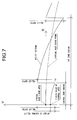
- FIG.17 shows a relief pattern 80 in profile as a fifth embodiment of this invention.
- a synchronous structure where two reliefs with the dioptric power at +3.0D for near vision and at +1.0D for intermediate vision are periodically overlapped. Meanwhile, the grating pitch is larger in the relief for intermediate vision than in the relief for near vision.
- the relief pattern 80 of the present embodiment is in a similar form to that of the relief pattern 50 (see FIG.11 ) as the above second embodiment, and especially in the present embodiment, only the relief component for near vision is made to increase outward from the center at zero as compared to the relief pattern 50 as the above second embodiment. This makes it possible to reduce diffractive intensity for near vision.
- FIG.18 shows a computer simulation result of diffractive intensity along the optical axis obtained by the relief pattern 80 according to the present invention, as was done in the above first embodiment. As evident from FIG.18 , it is confirmed that a peak of diffraction intensity at the focus for near vision can be reduced, according to the present embodiment, as compared to the above second embodiment (see FIG.12 ).
- a diffraction grating with a synchronous structure where multiple reliefs are periodically overlapped was formed almost all over the optical front surface 16 of the optical part 12, but it will suffice for such a diffraction grating to be formed in at least a part of the area in the radial direction of the lens, for example, only in the middle of the optical front surface 16 in the radial direction. Consequently, only a single relief can be formed or the like in the other part of the area.
- the relief pattern 24 formed on the intraocular lens 10 as the above first embodiment it is of course possible to form the diffraction grating with a synchronous structure on the optical rear surface 18.
- the lens surface where the diffraction grating with a synchronous structure is formed is not limited to refractive surfaces.
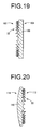
- the diffraction grating 22 can be formed on a plane 102, one of the two planes 102 and 104 of an optical part 100 of an intraocular lens as a different aspect of this invention, or as shown diagrammatically in FIG.20 , the diffraction grating 22 can even be formed on a plane 112 of an optical part 110 of an intraocular lens as a further different aspect of this invention where one surface is the flat plane 112 and the other is a curved plane 114 as refractive surface.
- a diffraction grating according to this invention for example, on a surface of a laminate of two materials with different dispersion, as described in JP-A-2001-42112 .
- the comparative example 1 as compared to the working example according to the above first embodiment (see FIG.6 ), a computer simulation has been performed of diffraction intensity obtained by a relief pattern of a bifocal lens according to the conventional structure.
- the relief pattern of the comparative example 1 was set at a dioptric power of +4.00D for near vision.
- a result of such simulation is shown in FIG.21 .
- an intraocular lens having a relief pattern with an asynchronous structure where the reliefs for near vision and intermediate vision are simply overlapped with no synchronization prepared.
- an intraocular lens in a biconvex form was set to have its dioptric power at +20.0D, refractive index of the lens material at 1.500, refractive index of the surrounding medium at 1.336, and design wavelength at 500nm, while the relief for near vision with the dioptric power at +4.00D and the relief for intermediate vision with the dioptric power at +2.00D, with each zone constant set at 1, were overlapped in an asynchronous form to set a relief pattern, which was formed on the optical front surface.
- FIGS.23 and 24 show the relief profiles of the relief for near vision and intermediate vision, respectively.
- FIG.25 shows, as the comparative example 2, a relief profile which is an overlap of these reliefs for near vision and intermediate vision with no synchronization
- FIG.26 shows a simulation result of diffraction intensity obtained by the relief pattern of said comparative example 2.
- FIG.26 in the comparative example 2 which is a simple overlap of multiple relief patterns, it was confirmed that no obvious generation of peaks was detected in any of the 0th order light by the refractive surface, the first order diffractive light by the relief for near vision, or the first order diffractive light by the relief for intermediate vision, causing to generate peaks of unintended order of light.
- Intraocular lens Intraocular lens
- 12 Optical part
- 16 Optical front surface
- 20 Lens center axis
- 22 Diffraction grating
- 24 Relief pattern
- 26 Relief for near vision
- 28 Relief for intermediate vision.
Landscapes
- Health & Medical Sciences (AREA)
- Ophthalmology & Optometry (AREA)
- Cardiology (AREA)
- Oral & Maxillofacial Surgery (AREA)
- Transplantation (AREA)
- Engineering & Computer Science (AREA)
- Biomedical Technology (AREA)
- Heart & Thoracic Surgery (AREA)
- Vascular Medicine (AREA)
- Life Sciences & Earth Sciences (AREA)
- Animal Behavior & Ethology (AREA)
- General Health & Medical Sciences (AREA)
- Public Health (AREA)
- Veterinary Medicine (AREA)
- Prostheses (AREA)
- Eyeglasses (AREA)
Priority Applications (2)
| Application Number | Priority Date | Filing Date | Title |
|---|---|---|---|
| SI200931294T SI2377493T1 (sl) | 2009-01-06 | 2009-04-08 | Postopek izdelave afakične intraokularne leče |
| PL09837427T PL2377493T3 (pl) | 2009-01-06 | 2009-04-08 | Sposób wytwarzania afakijnych soczewek wewnątrzgałkowych |
Applications Claiming Priority (2)
| Application Number | Priority Date | Filing Date | Title |
|---|---|---|---|
| JP2009001169A JP5342244B2 (ja) | 2009-01-06 | 2009-01-06 | 無水晶体眼内レンズの製造方法 |
| PCT/JP2009/001631 WO2010079537A1 (ja) | 2009-01-06 | 2009-04-08 | 無水晶体眼内レンズの製造方法 |
Publications (3)
| Publication Number | Publication Date |
|---|---|
| EP2377493A1 true EP2377493A1 (de) | 2011-10-19 |
| EP2377493A4 EP2377493A4 (de) | 2014-12-17 |
| EP2377493B1 EP2377493B1 (de) | 2015-08-05 |
Family
ID=42316317
Family Applications (1)
| Application Number | Title | Priority Date | Filing Date |
|---|---|---|---|
| EP09837427.5A Active EP2377493B1 (de) | 2009-01-06 | 2009-04-08 | Verfahren zur herstellung einer aphaken intraokularlinse |
Country Status (11)
| Country | Link |
|---|---|
| US (1) | US8500805B2 (de) |
| EP (1) | EP2377493B1 (de) |
| JP (1) | JP5342244B2 (de) |
| DE (1) | DE202009018881U1 (de) |
| DK (1) | DK2377493T3 (de) |
| ES (1) | ES2551158T3 (de) |
| HU (1) | HUE027966T2 (de) |
| PL (1) | PL2377493T3 (de) |
| PT (1) | PT2377493E (de) |
| SI (1) | SI2377493T1 (de) |
| WO (1) | WO2010079537A1 (de) |
Cited By (18)
| Publication number | Priority date | Publication date | Assignee | Title |
|---|---|---|---|---|
| WO2010093975A2 (en) | 2009-02-12 | 2010-08-19 | The Arizona Board Of Regents On Behalf Of The University Of Arizona | Diffractive trifocal lens |
| EP2813881A4 (de) * | 2012-02-09 | 2015-07-08 | Menicon Co Ltd | Multifokale diffraktionsaugenlinse und herstellungsverfahren dafür |
| EP2945009B1 (de) * | 2014-05-15 | 2017-07-19 | Novartis AG | Multifokale, diffraktive ophthalmische Linse mit einer unterdrückten Beugungsordnung |
| WO2018150236A1 (en) * | 2017-02-14 | 2018-08-23 | Dave, Jagrat Natavar | Diffractive multifocal implantable lens device |
| WO2018234552A1 (en) * | 2017-06-23 | 2018-12-27 | Amo Groningen B.V. | INTRAOCULAR LENSES FOR TREATMENT AGAINST PRESBYOPIA |
| WO2019002390A1 (en) * | 2017-06-28 | 2019-01-03 | Amo Groningen B.V. | EXTENDED BEACH AND ASSOCIATED INTRAOCULAR LENSES FOR THE TREATMENT OF PRESBYOPIA |
| WO2019002555A1 (en) * | 2017-06-30 | 2019-01-03 | Amo Groningen B.V. | NON REPEATED SCHOOLS AND ASSOCIATED INTRAOCULAR LENSES FOR THE TREATMENT OF PRESBYOPIA |
| EP3435143A1 (de) | 2017-07-26 | 2019-01-30 | VSY Biyoteknoloji Ve Ilac Sanayi Anonim Sirketi | Multifokale ophthalmische diffraktionslinse |
| US11022815B2 (en) | 2012-08-31 | 2021-06-01 | Amo Groningen B.V. | Multi-ring lens, systems and methods for extended depth of focus |
| US11129707B2 (en) | 2015-08-12 | 2021-09-28 | Physiol S.A. | Trifocal intraocular lens with extended range of vision and correction of longitudinal chromatic aberration |
| EP3939543A1 (de) * | 2020-07-15 | 2022-01-19 | Hoya Corporation | Multifokallinse |
| WO2022039682A1 (en) | 2020-08-21 | 2022-02-24 | Vsy Biyoteknoloji Ve Ilac Sanayi A.S. | A zonal diffractive ocular lens |
| WO2022039683A1 (en) | 2020-08-21 | 2022-02-24 | Vsy Biyoteknoloji Ve Ilac Sanayi A.S. | A zonal diffractive ocular lens |
| US11262598B2 (en) | 2017-06-28 | 2022-03-01 | Amo Groningen, B.V. | Diffractive lenses and related intraocular lenses for presbyopia treatment |
| US11324588B2 (en) | 2018-04-09 | 2022-05-10 | Mediphacos Industrias Medicas S/A | Diffractive intraocular lens |
| WO2022177517A1 (en) | 2021-02-19 | 2022-08-25 | Vsy Biyoteknoloji Ve Ilac Sanayi A.S. | An adaptive multifocal diffractive ocular lens |
| US11497599B2 (en) | 2017-03-17 | 2022-11-15 | Amo Groningen B.V. | Diffractive intraocular lenses for extended range of vision |
| US11844689B2 (en) | 2019-12-30 | 2023-12-19 | Amo Groningen B.V. | Achromatic lenses and lenses having diffractive profiles with irregular width for vision treatment |
Families Citing this family (26)
| Publication number | Priority date | Publication date | Assignee | Title |
|---|---|---|---|---|
| WO2010079528A1 (ja) * | 2009-01-06 | 2010-07-15 | 株式会社メニコン | 回折レンズの製造方法 |
| BE1019161A5 (fr) * | 2010-01-26 | 2012-04-03 | Physiol | Lentille intraoculaire. |
| NL2007285C2 (en) * | 2011-08-19 | 2013-02-21 | Oculentis B V | Intraocular lens. |
| US9658471B2 (en) | 2012-02-09 | 2017-05-23 | Menicon Co., Ltd. | Multifocal ophthalmic lens having a focal point formation region and a cancellation region and manufacturing method thereof |
| DE102013216015B4 (de) | 2013-08-13 | 2021-01-28 | Carl Zeiss Meditec Ag | Multifokale Augenlinse mit zumindest teilweise um eine optische Hauptachse umlaufenden optischen Zonen |
| US10285806B2 (en) * | 2014-05-15 | 2019-05-14 | Novartis Ag | Multifocal diffractive ophthalmic lens |
| US11000366B2 (en) | 2014-05-15 | 2021-05-11 | Alcon Inc. | Multifocal diffractive ophthalmic lens |
| EP3179293B1 (de) * | 2014-08-08 | 2024-06-26 | Menicon Co., Ltd. | Diffraktive multifokale linse und verfahren zur herstellung einer diffraktiven multifokalen linse |
| JP6653252B2 (ja) | 2014-08-08 | 2020-02-26 | 株式会社メニコン | 眼用回折多焦点レンズの製造方法および眼用回折多焦点レンズ |
| EP3358395A4 (de) | 2015-10-01 | 2019-05-22 | Menicon Co., Ltd. | Diffraktive multifokale okularlinse und verfahren zur herstellung einer diffraktiven multifokalen okularlinse |
| EP3150170B1 (de) * | 2015-10-02 | 2017-12-06 | Rayner Intraocular Lenses Limited | Multifokale linse und verfahren zu deren herstellung |
| EP3150169B1 (de) | 2015-10-02 | 2018-03-14 | Rayner Intraocular Lenses Limited | Multifokale linse |
| WO2017138099A1 (ja) | 2016-02-09 | 2017-08-17 | 株式会社メニコン | 眼用回折多焦点レンズおよび眼用回折多焦点レンズの製造方法 |
| WO2017137839A1 (en) | 2016-02-09 | 2017-08-17 | Amo Groningen B.V. | Progressive power intraocular lens, and methods of use and manufacture |
| US10675146B2 (en) * | 2016-02-24 | 2020-06-09 | Alcon Inc. | Multifocal lens having reduced visual disturbances |
| US10568734B2 (en) * | 2016-03-03 | 2020-02-25 | Novartis Ag | Adjusting the apodization pattern for diffractive IOLs |
| US10531950B2 (en) | 2016-11-16 | 2020-01-14 | Tatvum LLC | Intraocular lens having an extended depth of focus |
| US10433951B2 (en) * | 2017-05-22 | 2019-10-08 | Rxsight, Inc. | Depth of focus and visual acuity using colorized apodization of intra-ocular lenses |
| EP3731782B1 (de) * | 2017-12-28 | 2022-02-23 | Medicontur Orvostechnikai KFT. | Trifokale künstliche augenlinse und verfahren zu deren herstellung |
| EP4254024A3 (de) * | 2018-09-13 | 2023-11-08 | Hanita Lenses R.C.A. | Multifokale intraokularlinse |
| US11106056B2 (en) | 2019-03-28 | 2021-08-31 | Aizhong Zhang | Subzonal multifocal diffractive lens |
| CN112198577B (zh) * | 2019-10-23 | 2022-04-26 | 东莞东阳光医疗智能器件研发有限公司 | 眼科透镜 |
| US11719958B2 (en) | 2020-02-04 | 2023-08-08 | Valdemar Portney | Multi-chamber switchable optical element |
| US20230314838A1 (en) * | 2022-04-01 | 2023-10-05 | Valdemar Portney | Diffractive multifocal small aperture ophthalmic lens |
| DE102022209520A1 (de) | 2022-09-12 | 2024-03-14 | Carl Zeiss Meditec Ag | Ophthalmische linse und verfahren zum designen und zur herstellung einer solchen |
| WO2024144487A1 (en) | 2022-12-30 | 2024-07-04 | Vsy Biyoteknoloji Ve Ilac Sanayi A.S. | A multifocal diffractive ocular lens with adaptive power |
Citations (3)
| Publication number | Priority date | Publication date | Assignee | Title |
|---|---|---|---|---|
| EP0393639A2 (de) * | 1989-04-19 | 1990-10-24 | Allen L. Dr. Cohen | Multifokallinse mit kleiner Apertur |
| US5122903A (en) * | 1989-03-15 | 1992-06-16 | Omron Corporation | Optical device and optical pickup device using the same |
| WO2006047698A1 (en) * | 2004-10-25 | 2006-05-04 | Advanced Medical Optics, Inc. | Ophthalmic lens with multiple phase plates |
Family Cites Families (13)
| Publication number | Priority date | Publication date | Assignee | Title |
|---|---|---|---|---|
| BR8807089A (pt) * | 1987-06-01 | 1989-10-17 | Valdemar Portney | Lente oftalmica e processo para formar a mesma |
| US5283690A (en) * | 1989-04-04 | 1994-02-01 | Sharp Kabushiki Kaisha | Optical diffraction grating element |
| US4936666A (en) | 1989-08-08 | 1990-06-26 | Minnesota Mining And Manufacturing Company | Diffractive lens |
| US5178636A (en) | 1990-05-14 | 1993-01-12 | Iolab Corporation | Tuned fresnel lens for multifocal intraocular applications including small incision surgeries |
| US5589982A (en) | 1994-06-03 | 1996-12-31 | Rochester Photonics Corporation | Polychromatic diffractive lens |
| JP3530776B2 (ja) | 1999-07-28 | 2004-05-24 | キヤノン株式会社 | 回折光学素子及びそれを用いた光学系 |
| JP4587418B2 (ja) * | 2000-09-27 | 2010-11-24 | キヤノン株式会社 | 回折光学素子及び該回折光学素子を有する光学系 |
| EP1279992A3 (de) | 2001-07-28 | 2004-12-01 | ESCHENBACH OPTIK GmbH + Co. | Linse zum Einbau in eine Brillenfassung |
| US7025456B2 (en) | 2004-08-20 | 2006-04-11 | Apollo Optical Systems, Llc | Diffractive lenses for vision correction |
| US7188949B2 (en) | 2004-10-25 | 2007-03-13 | Advanced Medical Optics, Inc. | Ophthalmic lens with multiple phase plates |
| US7481532B2 (en) * | 2006-02-09 | 2009-01-27 | Alcon, Inc. | Pseudo-accommodative IOL having multiple diffractive patterns |
| US7572007B2 (en) | 2006-08-02 | 2009-08-11 | Alcon, Inc. | Apodized diffractive IOL with frustrated diffractive region |
| WO2010079528A1 (ja) | 2009-01-06 | 2010-07-15 | 株式会社メニコン | 回折レンズの製造方法 |
-
2009
- 2009-01-06 JP JP2009001169A patent/JP5342244B2/ja active Active
- 2009-04-08 DK DK09837427.5T patent/DK2377493T3/en active
- 2009-04-08 HU HUE09837427A patent/HUE027966T2/en unknown
- 2009-04-08 PL PL09837427T patent/PL2377493T3/pl unknown
- 2009-04-08 WO PCT/JP2009/001631 patent/WO2010079537A1/ja active Application Filing
- 2009-04-08 US US13/142,995 patent/US8500805B2/en active Active
- 2009-04-08 PT PT98374275T patent/PT2377493E/pt unknown
- 2009-04-08 DE DE202009018881.7U patent/DE202009018881U1/de not_active Expired - Lifetime
- 2009-04-08 ES ES09837427.5T patent/ES2551158T3/es active Active
- 2009-04-08 EP EP09837427.5A patent/EP2377493B1/de active Active
- 2009-04-08 SI SI200931294T patent/SI2377493T1/sl unknown
Patent Citations (3)
| Publication number | Priority date | Publication date | Assignee | Title |
|---|---|---|---|---|
| US5122903A (en) * | 1989-03-15 | 1992-06-16 | Omron Corporation | Optical device and optical pickup device using the same |
| EP0393639A2 (de) * | 1989-04-19 | 1990-10-24 | Allen L. Dr. Cohen | Multifokallinse mit kleiner Apertur |
| WO2006047698A1 (en) * | 2004-10-25 | 2006-05-04 | Advanced Medical Optics, Inc. | Ophthalmic lens with multiple phase plates |
Non-Patent Citations (1)
| Title |
|---|
| See also references of WO2010079537A1 * |
Cited By (40)
| Publication number | Priority date | Publication date | Assignee | Title |
|---|---|---|---|---|
| US10209533B2 (en) | 2009-02-12 | 2019-02-19 | The Arizona Board Of Regents On Behalf Of The University Of Arizona | Diffractive trifocal lens |
| WO2010093975A2 (en) | 2009-02-12 | 2010-08-19 | The Arizona Board Of Regents On Behalf Of The University Of Arizona | Diffractive trifocal lens |
| US11693260B2 (en) | 2009-02-12 | 2023-07-04 | Arizona Board Of Regents On Behalf Of The University Of Arizona | Diffractive trifocal lens |
| US11199725B2 (en) | 2009-02-12 | 2021-12-14 | Arizona Board Of Regents On Behalf Of The University Of Arizona | Diffractive trifocal lens |
| EP2396683A2 (de) | 2009-02-12 | 2011-12-21 | The Arizona Board Of Regents On Behalf Of The University Of Arizona | Diffraktive trifokale linse |
| EP2396683B1 (de) * | 2009-02-12 | 2020-04-08 | The Arizona Board Of Regents On Behalf Of The University Of Arizona | Diffraktive trifokale linse |
| US10725320B2 (en) | 2009-02-12 | 2020-07-28 | Arizona Board Of Regents On Behalf Of The University Of Arizona | Diffractive trifocal lens |
| US9563070B2 (en) | 2012-02-09 | 2017-02-07 | Menicon Co., Ltd. | Diffraction-type multifocal ophthalmic lens and manufacturing method thereof |
| EP2813881A4 (de) * | 2012-02-09 | 2015-07-08 | Menicon Co Ltd | Multifokale diffraktionsaugenlinse und herstellungsverfahren dafür |
| US11022815B2 (en) | 2012-08-31 | 2021-06-01 | Amo Groningen B.V. | Multi-ring lens, systems and methods for extended depth of focus |
| EP3242154A1 (de) * | 2014-05-15 | 2017-11-08 | Novartis AG | Multifokale, brechende ophthalmische linse unter verwendung von unterdrückter brechungsreihenfolge |
| US10278811B2 (en) | 2014-05-15 | 2019-05-07 | Novartis Ag | Multifocal diffractive ophthalmic lens using suppressed diffractive order |
| AU2015200449B2 (en) * | 2014-05-15 | 2019-08-29 | Alcon Inc. | Multifocal diffractive ophthalmic lens using suppressed diffractive order |
| EP2945009B1 (de) * | 2014-05-15 | 2017-07-19 | Novartis AG | Multifokale, diffraktive ophthalmische Linse mit einer unterdrückten Beugungsordnung |
| US11129707B2 (en) | 2015-08-12 | 2021-09-28 | Physiol S.A. | Trifocal intraocular lens with extended range of vision and correction of longitudinal chromatic aberration |
| KR20190113972A (ko) * | 2017-02-14 | 2019-10-08 | 데이브, 자그래트 나타바르 | 회절형 다초점 이식 가능 렌즈 장치 |
| CN110753528A (zh) * | 2017-02-14 | 2020-02-04 | 杰拉特·纳塔瓦·戴夫 | 衍射式多焦点可植入透镜装置 |
| WO2018150236A1 (en) * | 2017-02-14 | 2018-08-23 | Dave, Jagrat Natavar | Diffractive multifocal implantable lens device |
| US11497599B2 (en) | 2017-03-17 | 2022-11-15 | Amo Groningen B.V. | Diffractive intraocular lenses for extended range of vision |
| WO2018234552A1 (en) * | 2017-06-23 | 2018-12-27 | Amo Groningen B.V. | INTRAOCULAR LENSES FOR TREATMENT AGAINST PRESBYOPIA |
| AU2018287249B2 (en) * | 2017-06-23 | 2024-03-07 | Amo Groningen B.V. | Intraocular lenses for presbyopia treatment |
| US11523897B2 (en) | 2017-06-23 | 2022-12-13 | Amo Groningen B.V. | Intraocular lenses for presbyopia treatment |
| US11156853B2 (en) | 2017-06-28 | 2021-10-26 | Amo Groningen B.V. | Extended range and related intraocular lenses for presbyopia treatment |
| US11914229B2 (en) | 2017-06-28 | 2024-02-27 | Amo Groningen B.V. | Diffractive lenses and related intraocular lenses for presbyopia treatment |
| AU2018292030B2 (en) * | 2017-06-28 | 2024-02-08 | Amo Groningen B.V. | Extended range and related intraocular lenses for presbyopia treatment |
| WO2019002390A1 (en) * | 2017-06-28 | 2019-01-03 | Amo Groningen B.V. | EXTENDED BEACH AND ASSOCIATED INTRAOCULAR LENSES FOR THE TREATMENT OF PRESBYOPIA |
| US11573433B2 (en) | 2017-06-28 | 2023-02-07 | Amo Groningen B.V. | Extended range and related intraocular lenses for presbyopia treatment |
| US11262598B2 (en) | 2017-06-28 | 2022-03-01 | Amo Groningen, B.V. | Diffractive lenses and related intraocular lenses for presbyopia treatment |
| WO2019002555A1 (en) * | 2017-06-30 | 2019-01-03 | Amo Groningen B.V. | NON REPEATED SCHOOLS AND ASSOCIATED INTRAOCULAR LENSES FOR THE TREATMENT OF PRESBYOPIA |
| US11327210B2 (en) | 2017-06-30 | 2022-05-10 | Amo Groningen B.V. | Non-repeating echelettes and related intraocular lenses for presbyopia treatment |
| EP3435143A1 (de) | 2017-07-26 | 2019-01-30 | VSY Biyoteknoloji Ve Ilac Sanayi Anonim Sirketi | Multifokale ophthalmische diffraktionslinse |
| US11556018B2 (en) | 2017-07-26 | 2023-01-17 | Vsy Biyoteknoloji Ve Ilaç San. A.S. | Ophthalmic multifocal diffractive lens |
| WO2019020435A1 (en) | 2017-07-26 | 2019-01-31 | Vsy Biyoteknoloji Ve Ilaç San. A.S. | MULTIFOCAL OPHTHALMIC DIFFRACTIVE LENS |
| US11324588B2 (en) | 2018-04-09 | 2022-05-10 | Mediphacos Industrias Medicas S/A | Diffractive intraocular lens |
| US11844689B2 (en) | 2019-12-30 | 2023-12-19 | Amo Groningen B.V. | Achromatic lenses and lenses having diffractive profiles with irregular width for vision treatment |
| WO2022014723A1 (en) * | 2020-07-15 | 2022-01-20 | Hoya Corporation | Multifocal lens |
| EP3939543A1 (de) * | 2020-07-15 | 2022-01-19 | Hoya Corporation | Multifokallinse |
| WO2022039683A1 (en) | 2020-08-21 | 2022-02-24 | Vsy Biyoteknoloji Ve Ilac Sanayi A.S. | A zonal diffractive ocular lens |
| WO2022039682A1 (en) | 2020-08-21 | 2022-02-24 | Vsy Biyoteknoloji Ve Ilac Sanayi A.S. | A zonal diffractive ocular lens |
| WO2022177517A1 (en) | 2021-02-19 | 2022-08-25 | Vsy Biyoteknoloji Ve Ilac Sanayi A.S. | An adaptive multifocal diffractive ocular lens |
Also Published As
| Publication number | Publication date |
|---|---|
| PL2377493T3 (pl) | 2016-01-29 |
| JP5342244B2 (ja) | 2013-11-13 |
| ES2551158T3 (es) | 2015-11-16 |
| US8500805B2 (en) | 2013-08-06 |
| JP2010158315A (ja) | 2010-07-22 |
| HUE027966T2 (en) | 2016-11-28 |
| SI2377493T1 (sl) | 2016-01-29 |
| EP2377493A4 (de) | 2014-12-17 |
| WO2010079537A1 (ja) | 2010-07-15 |
| EP2377493B1 (de) | 2015-08-05 |
| PT2377493E (pt) | 2015-11-12 |
| US20110270390A1 (en) | 2011-11-03 |
| DE202009018881U1 (de) | 2014-02-25 |
| DK2377493T3 (en) | 2015-11-09 |
Similar Documents
| Publication | Publication Date | Title |
|---|---|---|
| EP2377493B1 (de) | Verfahren zur herstellung einer aphaken intraokularlinse | |
| EP2378319B1 (de) | Verfahren zur herstellung einer diffraktiven linse | |
| AU2022203187B2 (en) | Multifocal lens having reduced visual disturbances | |
| EP3423004B1 (de) | Einstellung des apodisierungsmusters für diffraktive intraokularlinsen | |
| CN103054659B (zh) | 具有受抑衍射区的切趾衍射式人工晶状体 | |
| KR101309604B1 (ko) | 상이한 영역을 갖는 회절 존을 지닌 유사적응성 안구내 렌즈 | |
| EP2908777B1 (de) | System zur bereitstellung einer intraokularlinse mit verbesserter tiefenschärfe | |
| KR101314775B1 (ko) | 다중 회절 패턴을 가지는 유사-조절용 iol | |
| KR102635338B1 (ko) | 회절형 다초점 이식 가능 렌즈 장치 | |
| JP2011507628A (ja) | 回折成分、トーリック成分、及び非球面成分の組合せを有するレンズ表面 | |
| US20140211313A1 (en) | Lens having an extended range of focus and method of making the same | |
| CN112004499A (zh) | 具有优化变迹的衍射人工眼科镜片以及生产这种人工眼科镜片的方法 | |
| US20090240328A1 (en) | Multifocal intraocular lens | |
| JP2011507628A5 (de) | ||
| US20240094558A1 (en) | Ophthalmic lens and method for designing an ophthalmic lens | |
| US20200085569A1 (en) | Artifical eye lens with diffractive grating structure and method for producing an artificial eye lens | |
| US20230098580A1 (en) | Lens providing both positive and negative diffraction |
Legal Events
| Date | Code | Title | Description |
|---|---|---|---|
| PUAI | Public reference made under article 153(3) epc to a published international application that has entered the european phase |
Free format text: ORIGINAL CODE: 0009012 |
|
| 17P | Request for examination filed |
Effective date: 20110711 |
|
| AK | Designated contracting states |
Kind code of ref document: A1 Designated state(s): AT BE BG CH CY CZ DE DK EE ES FI FR GB GR HR HU IE IS IT LI LT LU LV MC MK MT NL NO PL PT RO SE SI SK TR |
|
| DAX | Request for extension of the european patent (deleted) | ||
| RAP1 | Party data changed (applicant data changed or rights of an application transferred) |
Owner name: CARL ZEISS MEDITEC AG |
|
| A4 | Supplementary search report drawn up and despatched |
Effective date: 20141113 |
|
| RIC1 | Information provided on ipc code assigned before grant |
Ipc: A61F 2/16 20060101AFI20141107BHEP |
|
| GRAP | Despatch of communication of intention to grant a patent |
Free format text: ORIGINAL CODE: EPIDOSNIGR1 |
|
| GRAS | Grant fee paid |
Free format text: ORIGINAL CODE: EPIDOSNIGR3 |
|
| GRAA | (expected) grant |
Free format text: ORIGINAL CODE: 0009210 |
|
| STAA | Information on the status of an ep patent application or granted ep patent |
Free format text: STATUS: THE PATENT HAS BEEN GRANTED |
|
| INTG | Intention to grant announced |
Effective date: 20150610 |
|
| AK | Designated contracting states |
Kind code of ref document: B1 Designated state(s): AT BE BG CH CY CZ DE DK EE ES FI FR GB GR HR HU IE IS IT LI LT LU LV MC MK MT NL NO PL PT RO SE SI SK TR |
|
| REG | Reference to a national code |
Ref country code: GB Ref legal event code: FG4D |
|
| REG | Reference to a national code |
Ref country code: CH Ref legal event code: EP |
|
| REG | Reference to a national code |
Ref country code: AT Ref legal event code: REF Ref document number: 740237 Country of ref document: AT Kind code of ref document: T Effective date: 20150815 |
|
| REG | Reference to a national code |
Ref country code: IE Ref legal event code: FG4D |
|
| REG | Reference to a national code |
Ref country code: DE Ref legal event code: R096 Ref document number: 602009032734 Country of ref document: DE |
|
| REG | Reference to a national code |
Ref country code: DK Ref legal event code: T3 Effective date: 20151103 |
|
| REG | Reference to a national code |
Ref country code: PT Ref legal event code: SC4A Free format text: AVAILABILITY OF NATIONAL TRANSLATION Effective date: 20151023 |
|
| REG | Reference to a national code |
Ref country code: ES Ref legal event code: FG2A Ref document number: 2551158 Country of ref document: ES Kind code of ref document: T3 Effective date: 20151116 |
|
| REG | Reference to a national code |
Ref country code: SE Ref legal event code: TRGR |
|
| REG | Reference to a national code |
Ref country code: LT Ref legal event code: MG4D |
|
| REG | Reference to a national code |
Ref country code: NL Ref legal event code: FP |
|
| REG | Reference to a national code |
Ref country code: NO Ref legal event code: T2 Effective date: 20150805 |
|
| PG25 | Lapsed in a contracting state [announced via postgrant information from national office to epo] |
Ref country code: LT Free format text: LAPSE BECAUSE OF FAILURE TO SUBMIT A TRANSLATION OF THE DESCRIPTION OR TO PAY THE FEE WITHIN THE PRESCRIBED TIME-LIMIT Effective date: 20150805 Ref country code: LV Free format text: LAPSE BECAUSE OF FAILURE TO SUBMIT A TRANSLATION OF THE DESCRIPTION OR TO PAY THE FEE WITHIN THE PRESCRIBED TIME-LIMIT Effective date: 20150805 Ref country code: GR Free format text: LAPSE BECAUSE OF FAILURE TO SUBMIT A TRANSLATION OF THE DESCRIPTION OR TO PAY THE FEE WITHIN THE PRESCRIBED TIME-LIMIT Effective date: 20151106 |
|
| PG25 | Lapsed in a contracting state [announced via postgrant information from national office to epo] |
Ref country code: HR Free format text: LAPSE BECAUSE OF FAILURE TO SUBMIT A TRANSLATION OF THE DESCRIPTION OR TO PAY THE FEE WITHIN THE PRESCRIBED TIME-LIMIT Effective date: 20150805 |
|
| REG | Reference to a national code |
Ref country code: SK Ref legal event code: T3 Ref document number: E 19624 Country of ref document: SK |
|
| REG | Reference to a national code |
Ref country code: FR Ref legal event code: PLFP Year of fee payment: 8 |
|
| PG25 | Lapsed in a contracting state [announced via postgrant information from national office to epo] |
Ref country code: EE Free format text: LAPSE BECAUSE OF FAILURE TO SUBMIT A TRANSLATION OF THE DESCRIPTION OR TO PAY THE FEE WITHIN THE PRESCRIBED TIME-LIMIT Effective date: 20150805 |
|
| REG | Reference to a national code |
Ref country code: DE Ref legal event code: R026 Ref document number: 602009032734 Country of ref document: DE |
|
| PLBI | Opposition filed |
Free format text: ORIGINAL CODE: 0009260 |
|
| PG25 | Lapsed in a contracting state [announced via postgrant information from national office to epo] |
Ref country code: RO Free format text: LAPSE BECAUSE OF FAILURE TO SUBMIT A TRANSLATION OF THE DESCRIPTION OR TO PAY THE FEE WITHIN THE PRESCRIBED TIME-LIMIT Effective date: 20150805 |
|
| 26 | Opposition filed |
Opponent name: VSY BIOTECHNOLOGY B.V./VSY BIYOTEKNOLOJI VE ILAC S Effective date: 20160506 |
|
| PLAX | Notice of opposition and request to file observation + time limit sent |
Free format text: ORIGINAL CODE: EPIDOSNOBS2 |
|
| PLBB | Reply of patent proprietor to notice(s) of opposition received |
Free format text: ORIGINAL CODE: EPIDOSNOBS3 |
|
| REG | Reference to a national code |
Ref country code: HU Ref legal event code: AG4A Ref document number: E027966 Country of ref document: HU |
|
| PG25 | Lapsed in a contracting state [announced via postgrant information from national office to epo] |
Ref country code: LU Free format text: LAPSE BECAUSE OF FAILURE TO SUBMIT A TRANSLATION OF THE DESCRIPTION OR TO PAY THE FEE WITHIN THE PRESCRIBED TIME-LIMIT Effective date: 20160408 |
|
| REG | Reference to a national code |
Ref country code: FR Ref legal event code: PLFP Year of fee payment: 9 |
|
| REG | Reference to a national code |
Ref country code: DE Ref legal event code: R100 Ref document number: 602009032734 Country of ref document: DE |
|
| REG | Reference to a national code |
Ref country code: AT Ref legal event code: UEP Ref document number: 740237 Country of ref document: AT Kind code of ref document: T Effective date: 20150805 |
|
| PLCK | Communication despatched that opposition was rejected |
Free format text: ORIGINAL CODE: EPIDOSNREJ1 |
|
| STAA | Information on the status of an ep patent application or granted ep patent |
Free format text: STATUS: THE PATENT HAS BEEN GRANTED |
|
| REG | Reference to a national code |
Ref country code: FR Ref legal event code: PLFP Year of fee payment: 10 |
|
| PG25 | Lapsed in a contracting state [announced via postgrant information from national office to epo] |
Ref country code: CY Free format text: LAPSE BECAUSE OF FAILURE TO SUBMIT A TRANSLATION OF THE DESCRIPTION OR TO PAY THE FEE WITHIN THE PRESCRIBED TIME-LIMIT Effective date: 20150805 |
|
| APBM | Appeal reference recorded |
Free format text: ORIGINAL CODE: EPIDOSNREFNO |
|
| APBP | Date of receipt of notice of appeal recorded |
Free format text: ORIGINAL CODE: EPIDOSNNOA2O |
|
| APAH | Appeal reference modified |
Free format text: ORIGINAL CODE: EPIDOSCREFNO |
|
| PG25 | Lapsed in a contracting state [announced via postgrant information from national office to epo] |
Ref country code: MK Free format text: LAPSE BECAUSE OF FAILURE TO SUBMIT A TRANSLATION OF THE DESCRIPTION OR TO PAY THE FEE WITHIN THE PRESCRIBED TIME-LIMIT Effective date: 20150805 Ref country code: MT Free format text: LAPSE BECAUSE OF NON-PAYMENT OF DUE FEES Effective date: 20160430 |
|
| APBQ | Date of receipt of statement of grounds of appeal recorded |
Free format text: ORIGINAL CODE: EPIDOSNNOA3O |
|
| REG | Reference to a national code |
Ref country code: DE Ref legal event code: R100 Ref document number: 602009032734 Country of ref document: DE |
|
| APBU | Appeal procedure closed |
Free format text: ORIGINAL CODE: EPIDOSNNOA9O |
|
| PLBN | Opposition rejected |
Free format text: ORIGINAL CODE: 0009273 |
|
| STAA | Information on the status of an ep patent application or granted ep patent |
Free format text: STATUS: OPPOSITION REJECTED |
|
| P01 | Opt-out of the competence of the unified patent court (upc) registered |
Effective date: 20230530 |
|
| 27O | Opposition rejected |
Effective date: 20190121 |
|
| PGFP | Annual fee paid to national office [announced via postgrant information from national office to epo] |
Ref country code: NL Payment date: 20240418 Year of fee payment: 16 |
|
| PGFP | Annual fee paid to national office [announced via postgrant information from national office to epo] |
Ref country code: IS Payment date: 20240412 Year of fee payment: 16 |
|
| PGFP | Annual fee paid to national office [announced via postgrant information from national office to epo] |
Ref country code: IE Payment date: 20240419 Year of fee payment: 16 |
|
| PGFP | Annual fee paid to national office [announced via postgrant information from national office to epo] |
Ref country code: GB Payment date: 20240419 Year of fee payment: 16 |
|
| PGFP | Annual fee paid to national office [announced via postgrant information from national office to epo] |
Ref country code: DE Payment date: 20240418 Year of fee payment: 16 |
|
| PGFP | Annual fee paid to national office [announced via postgrant information from national office to epo] |
Ref country code: DK Payment date: 20240423 Year of fee payment: 16 Ref country code: MC Payment date: 20240422 Year of fee payment: 16 |
|
| PGFP | Annual fee paid to national office [announced via postgrant information from national office to epo] |
Ref country code: CH Payment date: 20240501 Year of fee payment: 16 |
|
| PGFP | Annual fee paid to national office [announced via postgrant information from national office to epo] |
Ref country code: ES Payment date: 20240524 Year of fee payment: 16 |
|
| PGFP | Annual fee paid to national office [announced via postgrant information from national office to epo] |
Ref country code: AT Payment date: 20240419 Year of fee payment: 16 Ref country code: CZ Payment date: 20240402 Year of fee payment: 16 |
|
| PGFP | Annual fee paid to national office [announced via postgrant information from national office to epo] |
Ref country code: SK Payment date: 20240403 Year of fee payment: 16 |
|
| PGFP | Annual fee paid to national office [announced via postgrant information from national office to epo] |
Ref country code: NO Payment date: 20240422 Year of fee payment: 16 Ref country code: IT Payment date: 20240424 Year of fee payment: 16 Ref country code: FR Payment date: 20240426 Year of fee payment: 16 Ref country code: FI Payment date: 20240425 Year of fee payment: 16 Ref country code: BG Payment date: 20240419 Year of fee payment: 16 Ref country code: SI Payment date: 20240328 Year of fee payment: 16 |
|
| PGFP | Annual fee paid to national office [announced via postgrant information from national office to epo] |
Ref country code: PL Payment date: 20240402 Year of fee payment: 16 Ref country code: PT Payment date: 20240328 Year of fee payment: 16 |
|
| PGFP | Annual fee paid to national office [announced via postgrant information from national office to epo] |
Ref country code: TR Payment date: 20240401 Year of fee payment: 16 Ref country code: SE Payment date: 20240418 Year of fee payment: 16 Ref country code: HU Payment date: 20240422 Year of fee payment: 16 Ref country code: BE Payment date: 20240418 Year of fee payment: 16 |