EP2377177B1 - Piezoelectric motor - Google Patents
Piezoelectric motor Download PDFInfo
- Publication number
- EP2377177B1 EP2377177B1 EP09837891.2A EP09837891A EP2377177B1 EP 2377177 B1 EP2377177 B1 EP 2377177B1 EP 09837891 A EP09837891 A EP 09837891A EP 2377177 B1 EP2377177 B1 EP 2377177B1
- Authority
- EP
- European Patent Office
- Prior art keywords
- piezoresonator
- piezoelectric device
- piezoelectric
- rotor
- longitudinal
- Prior art date
- Legal status (The legal status is an assumption and is not a legal conclusion. Google has not performed a legal analysis and makes no representation as to the accuracy of the status listed.)
- Not-in-force
Links
- 238000005452 bending Methods 0.000 claims description 28
- 230000005284 excitation Effects 0.000 claims description 16
- 238000013461 design Methods 0.000 description 7
- 238000006073 displacement reaction Methods 0.000 description 6
- 239000000446 fuel Substances 0.000 description 6
- 230000007246 mechanism Effects 0.000 description 3
- 238000000034 method Methods 0.000 description 3
- 230000008901 benefit Effects 0.000 description 2
- 230000015572 biosynthetic process Effects 0.000 description 2
- 230000015556 catabolic process Effects 0.000 description 2
- 238000006731 degradation reaction Methods 0.000 description 2
- 238000004377 microelectronic Methods 0.000 description 2
- 238000002406 microsurgery Methods 0.000 description 2
- 230000004075 alteration Effects 0.000 description 1
- 238000006243 chemical reaction Methods 0.000 description 1
- 230000003247 decreasing effect Effects 0.000 description 1
- 230000001419 dependent effect Effects 0.000 description 1
- 238000011161 development Methods 0.000 description 1
- 230000000694 effects Effects 0.000 description 1
- 239000012530 fluid Substances 0.000 description 1
- 238000010348 incorporation Methods 0.000 description 1
- 238000012986 modification Methods 0.000 description 1
- 230000004048 modification Effects 0.000 description 1
- 230000009467 reduction Effects 0.000 description 1
Images


Classifications
-
- H—ELECTRICITY
- H10—SEMICONDUCTOR DEVICES; ELECTRIC SOLID-STATE DEVICES NOT OTHERWISE PROVIDED FOR
- H10N—ELECTRIC SOLID-STATE DEVICES NOT OTHERWISE PROVIDED FOR
- H10N30/00—Piezoelectric or electrostrictive devices
- H10N30/20—Piezoelectric or electrostrictive devices with electrical input and mechanical output, e.g. functioning as actuators or vibrators
- H10N30/202—Piezoelectric or electrostrictive devices with electrical input and mechanical output, e.g. functioning as actuators or vibrators using longitudinal or thickness displacement combined with bending, shear or torsion displacement
- H10N30/2023—Piezoelectric or electrostrictive devices with electrical input and mechanical output, e.g. functioning as actuators or vibrators using longitudinal or thickness displacement combined with bending, shear or torsion displacement having polygonal or rectangular shape
-
- H—ELECTRICITY
- H02—GENERATION; CONVERSION OR DISTRIBUTION OF ELECTRIC POWER
- H02N—ELECTRIC MACHINES NOT OTHERWISE PROVIDED FOR
- H02N2/00—Electric machines in general using piezoelectric effect, electrostriction or magnetostriction
- H02N2/10—Electric machines in general using piezoelectric effect, electrostriction or magnetostriction producing rotary motion, e.g. rotary motors
- H02N2/103—Electric machines in general using piezoelectric effect, electrostriction or magnetostriction producing rotary motion, e.g. rotary motors by pressing one or more vibrators against the rotor
Description
- The invention relates to the field of electric motors, and specifically to the field of piezoelectric motors.
- In general, miniature electric motors are utilized in the fields of microsurgery, microbiology, and microelectronics, to name a few. Unfortunately, the miniaturization of electric motors for use in these and other fields is typically associated with a sharp decrease in motor efficiency. For example, as miniature electric motors are reduced to operate using diameters of less than 10 mm, it is not unusual to see efficiency degradation to as low as 2% or less. Even though this effect does not generally apply to the miniaturization of the piezoelectric motors, miniaturization itself can still lead to design complications. For example, miniaturized piezoelectric motors are generally prone to having poor reliability and experiencing degradation of motor parameters such as resolution, torque, and speed, to name a few.
- In general, the conventional piezoelectric motor designs incorporate a piezoelectric resonator with electrodes to stimulate the simultaneous excitation of longitudinal and bending vibrations. The piezoresonator interacts with a moving rotor by friction over a contact area between the resonator and rotor. In such motors, a flat piezoelectric resonator is generally used, in which both longitudinal and flexural deformations are excited.
- In some conventional piezoelectric motor designs, a drive mechanism can be provided which uses a rectangular piezoresonator with electrodes positioned to excite both longitudinal and lateral vibrations. Consequently, the piezoresonator can interact by contacting a moving part (rotor) through at least one contact pad. In general, the size of the resonator and the shape of the resonator electrodes are constructed to enable the simultaneous formation of the first longitudinal mode and the second bending mode of vibration along the length of the resonator. If the frequencies of these two modes are equal, the contact pad typically vibrates. In particular, the contact pad follows an elliptical path in a plane parallel to the plane containing all electrodes. Via friction, the contact pad causes rotation of the rotor. Such piezoresonators are typically polarized normal to the plane containing the electrodes with a common electrode occupying one flat surface of the piezoresonator. The opposite flat surface is generally divided into four symmetrically disposed sectors each one of which has an active electrode.
-
US 2004/189150 A1 discloses a linear-type ultrasonic actuator with a vibration element. The vibration element is composed of a piezoelectric element of an approximately rectangular shape and a driving plate on which four protruding portions are integrally formed. The piezoelectric element has two end surfaces separated by a length of the piezoelectric element. Six electrode films are formed on one of the end surfaces of the piezoelectric element. In operation, elliptical movements are generated at contact portions that are formed on the tips of the protruding portions. -
US 2006/006764 A1 discloses a piezoelectric motor with a piezoelectric vibrator having an axis of symmetry, and at least one friction nub having a center of mass displaced from the axis of symmetry. In some embodiments, the motor comprises three driving arms with three friction nubs, and a first longitudinal resonant vibration mode and a third resonant bending vibration mode of each driving arm are used to generate motion of the friction nubs. - The present invention is defined by
independent claim 1, taking due account of any element which is equivalent to an element specified in the claim. The dependent claims recite optional elements of some embodiments of the invention. - The embodiments of the invention concern piezoelectric motors. In a first embodiment of the invention, a piezoelectric motor is provided. The motor includes a piezoresonator body having opposing front and back surfaces and opposing first and second end surfaces. The front and the back surfaces are substantially parallel to first and second longitudinal axes of the piezoresonator body and the first and the second end surfaces are substantially perpendicular to the first longitudinal axis and substantially parallel to the second longitudinal axis and separated by a length (L) of the piezoresonator body. The motor also includes at least one common electrode disposed on the back surface and at least 6n excitation electrodes disposed across the front surface along L in two symmetric rows extending along L, where n is an integer ≥ 1. In the motor, the piezoelectric body has an nth order longitudinal vibration frequency (ν1) along L and a 3nth order bending vibration frequency (ν2) along L, and where ν1 and ν2 are substantially equal.
- In a second embodiment of the invention, a pump is provided. The pump includes a piezoelectric motor. The piezoelectric motor includes a piezoresonator body having opposing front and back surfaces and opposing first and second end surfaces. The front and the back surfaces are substantially parallel to first and second longitudinal axes of the piezoresonator body. The first and second end surfaces are substantially perpendicular to the first longitudinal axis and substantially parallel to the second longitudinal axis and separated by a length (L) of the piezoresonator body. The motor also includes at least one common electrode disposed on the back surface and at least 6n excitation electrodes disposed across the front surface along L in two symmetric rows extending along L, where n is an integer ≥ 1. In the motor, the piezoelectric body has an nth order longitudinal vibration frequency (ν1) along L and a 3nth order bending vibration frequency (ν2) along L, where ν1 and ν2 are substantially equal.
-
-
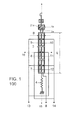
FIG. 1 is a schematic side view of an exemplary piezoelectric motor configured in accordance with an embodiment of the present invention. -
FIG. 2 is a perspective view of portions of the exemplary piezoelectric motor inFIG. 1 . -
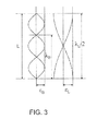
FIG. 3 is a plot of waveforms depicting the displacement of the piezoresonator in the first longitudinal vibrational mode and the third bending vibrational mode. -
FIGs. 4A and 4B are top and side views of a first exemplary configuration of a piezoelectric motor and a rotor in accordance with an embodiment of the present invention. -
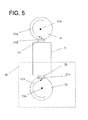
FIG. 5 is a side view of a second exemplary configuration of a piezoelectric motor and a rotor in accordance with an embodiment of the present invention. -
FIGs. 6A and6B are drawings that is useful for understanding how the invention can be used as a motive force for a fluid pump in a micro-fuel cell. - The present invention is described with reference to the attached figures, wherein like reference numerals are used throughout the figures to designate similar or equivalent elements. The figures are not drawn to scale and they are provided merely to illustrate the instant invention. Several aspects of the invention are described below with reference to example applications for illustration. It should be understood that numerous specific details, relationships, and methods are set forth to provide a full understanding of the invention. One having ordinary skill in the relevant art, however, will readily recognize that the invention can be practiced without one or more of the specific details or with other methods. In other instances, well-known structures or operations are not shown in detail to avoid obscuring the invention. The present invention is not limited by the illustrated ordering of acts or events, as some acts may occur in different orders and/or concurrently with other acts or events. Furthermore, not all illustrated acts or events are required to implement a methodology in accordance with the present invention.
- Embodiments of the present invention provide improved piezoelectric motors which can be used for the development of miniature piezoelectric rotary motors with a diameter of less than 10 mm. Such motors can be used for various applications, including, microsurgery, microbiology, and microelectronics, to name a few. As previously described, conventional piezoelectric motors are susceptible to problems as a result of miniaturization. In general, the minimization of such piezoelectric drive mechanisms is hindered by significant fundamental difficulties..
- In particular, miniaturization of the width of conventional piezoelectric motors, which determines the minimum diameter of the motor, can be problematic. For example, a miniaturization by less than an order of magnitude of the width of the resonator leads to a lower frequency of the bending mode of vibration. This lower frequency generally contributes to an increased disparity between the frequencies of the first longitudinal and the second bending modes, therefore limiting efficiency. Typically, to compensate for this frequency shift, an increase in the length of the resonator is required, which results in an increase in the motor length. Furthermore, side pressure-applying clips are typically required for holding or clamping the piezoresonator at waveform stationary points. These clips generally add significantly to the overall width, further limiting the minimum achievable width for the motor.
- Piezoelectric motors configured in accordance with the various embodiments of the present invention overcome the limitations of conventional miniaturized piezoelectric motors by allowing a minimization of the dimensions of the piezoelectric motor (in particular its outside diameter) with little or no increase in its length. This is primarily achieved by utilizing a piezoelectric resonator (piezoresonator) in which the first longitudinal mode and the third bending mode (instead of the second bending mode as in the prototype) are formed simultaneously along the length of the piezoresonator.
- Accordingly, the various embodiments of the present invention provide piezoelectric motors including a piezoresonator with electrodes and electrode leads for the simultaneous excitation of longitudinal and bending vibrational modes. In operation, the piezoelectric motor with a rotor via friction forces between the rotor and at least one contact pad on a first end of the piezoresonator. The contact pad can be applied to the rotor under pressure applied by a mechanical spring-like pressure device contacting a second opposite end of the piezoresonator. In some embodiments, the piezoresonator is made in the form of a thin rectangular plate or cuboid with length L and width B that is polarized normal to the flat surface (defined by L and B) having the electrodes fixed thereon.
- In general, the frequency ν1 of longitudinal vibrations along a length L of a piezoresonator for the first order mode has the form:

where λ1 is wavelength of the first longitudinal mode vibration which is formed along the length of the piezoresonator, L is the length of the piezoresonator, and C1 is speed of propagation of longitudinal vibrations in the piezoelectric resonator. The frequency ν2 of the bending vibrations along the length L of the resonator for the nth order vibrational mode is given by the expression:
where B is the width of the piezoresonator and C2 is the speed of propagation of bending vibrations in the piezoelectric resonator. For the third-order mode (n=3), equation (2) becomes:
- Furthermore to provide the resonance necessary for the formation of a nano-ellipse at the contact pad, ν1 = ν2. Therefore, setting equation (1) and equation (2) equal to each other provides:

or after rearranging:
- Therefore, if a piezoresonator is configured for using the third-order bending mode with resonator length of L = 37 mm, the width (outside diameter) according to equation (5) would be approximately B = 6.7 mm. In a conventional piezoelectric motor with the same length of L = 37 mm, the width would be approximately 10 mm. Accordingly, by configuring the piezoresonator to utilize the third order bending mode, the width of the piezoresonator (and hence the outer diameter of the piezoelectric motor) can be decreased to a width of approximately 2/3 of the width of conventional piezoelectric motors without increasing the length of the piezoresonator. Consequently, the size of the motor is significantly reduced. Additionally, a piezoelectric motor configured in accordance with an embodiment of the present invention has no need for the side pressure-applying clips that are required for conventional piezoelectric motors, further reducing the motor diameter. As a result, in some instances, a 50% reduction the size of piezoelectric motor can be provided by utilizing a piezoelectric motor configured in accordance with an embodiment of the present invention.
- An exemplary piezoelectric motor configured in accordance with an embodiment of the present invention will be described with respect to
FIGs. 1 and2 .FIG. 1 is a schematic side view of an exemplarypiezoelectric motor 100 configured in accordance with an embodiment of the present invention.FIG. 2 is a perspective view of portions of the exemplarypiezoelectric motor 100 inFIG. 1 . As shown inFIGs. 1 and2 , thepiezoelectric motor 100 includes apiezoresonator 3, acontact pad 2a coupled to afirst end 20 of the piezoresonator and aclip device 4, such as a spring, contacting asecond end 20 of thepiezoresonator 3. Thepiezoresonator 3 includes afront surface 17 and aback surface 18 substantially parallel to a plane defined bylongitudinal axes piezoresonator 3. Theclip device 4 can be used to apply thecontact pad 2a to therotor 1a. - In contrast to conventional piezoresonators, no additional clip devices are needed along the length of the
piezoresonator 3. The combination of the first order longitudinal vibrational mode and the third order bending vibrational mode results in generally symmetric deformation of thepiezoresonator 3 as compared to the typically asymmetric deformation of piezoresonators in conventional piezoelectric motors. Accordingly, no additional means for securing thepiezoresonator 3 andcontact pad 2a against the rotor are generally needed in the various embodiments of the present invention. - To form the first order longitudinal vibrational mode and the third order bending vibrational mode in the
piezoresonator 3, an alternating voltage needs to be applied toexcitation electrodes front surface 17 surface of thepiezoresonator 3 and acommon electrode 6 on aback surface 18 of thepiezoresonator 3. In particular, to enable such excitation modes themotor piezoresonator 3, as shown inFIGs. 1 and2 . As previously described, by selection of the width (B) and the length (L) of thepiezoresonator 3, both excitation modes can be enabled by providing an alternating voltage having an operating frequency of approximately ν1 or ν2. Furthermore, this alternating voltage is applied to a diagonal group of the electrodes 7-12 and thecommon electrode 6. The term "diagonal group", as used herein with respect to electrodes 7-12, refers to a group of the electrodes 7-12 along the length L which are located diagonally from each other. For example, for themotor 100 inFIGs. 1 and2 ,electrodes electrodes piezoresonator 3, resulting in the vibration of thecontact pad 2a in aelliptical path 21a. The vibration of thecontact pad 2a therefore results in thecontact pad 2a applying a force to therotor 1a, causing therotor 1a to rotate. - Forward and reverse motion of the
rotor 1a is provided by selection of the diagonal group. As described above, the arrangement of electrodes 7-12 provides a first and a second diagonal group. Therefore, to provide motion of therotor 1 in a first direction, the alternating voltage is applied to the first diagonal group (electrodes elliptical path 21a of thecontact pad 2a (clockwise rotation path) due to the alternating voltage at these electrodes (7, 9, 11) provides vibration that causes therotor 1 to rotate in a first direction. To provide motion of therotor 1 in a second direction, the alternating voltage is applied to the second diagonal group (electrodes contact pad 2a (opposite topath 21a) due to the alternating voltage at these electrodes (8, 10, 12) provides vibration that causes therotor 1a to rotate in a second direction opposite to the first direction. Such a configuration provides a relatively high efficiency motor, since the motion of thecontact pad 2 when in contact with therotor 1a is substantially in the same direction as the desired direction of rotation for therotor 1a. - As previously described, the
elliptical path 21a is provided by the combination of the displacement ofpiezoresonator 3 according to the first order longitudinal vibrational mode and the third order bending vibrational mode. A plot of each of these displacement types in shown inFIG. 3. FIG. 3 is a plot of waveforms depicting the displacement of the piezoresonator for the first order longitudinal vibrational mode and the third order bending vibrational mode along a first longitudinal axis. As shown inFIG. 3 , along the L length of thepiezoresonator 3 and along the first longitudinal axis, the amplitude of the dimensional changes along the length of thepiezoresonator 3 due to the first order vibrational mode is εL, where εL is the dimensional displacement in the direction of the length L. The amplitude of the dimensional changes along the length of thepiezoresonator 3 due to the third order being mode is εB, where εB is the dimensional displacement in a direction perpendicular to the length L, i.e. in the direction of the width B. λB is the wavelength of the bending deformation and λL is wavelength of the longitudinal deformation. As shown inFIG. 3 , the third order bending vibration mode provides a symmetric deformation of thepiezoresonator 3 along it length. Therefore, even though thepiezoresonator 3 causes thecontact pad 2 to vibrate in an elliptical path on thefirst end 20, no additional clips are necessary to support or secure thepiezoresonator 3 along its length, due to the symmetrical vibrations induced. - In general, the
rotor 1a and the piezoresonator can be arranged in various configurations. For example, the elliptical path of a contact pad and the axis of rotation of a rotor can be parallel.FIGs. 4A and 4B are top and side views, respectively, of a first exemplary configuration of thepiezoresonator 3, thecontact pad 2a, and therotor 1a in accordance with an embodiment of the present invention. As shown inFIGs. 4A and 4B , thepiezoresonator 3, thecontact pad 2a, and a cylindrical rotor I a are arranged to provide anelliptical path 21a (or an opposite elliptical path) for thecontact pad 2a that is parallel to arotational axis 23a of therotor 1a. That is thecontact pad 2a is arranged to contact the flat ends of thecylindrical rotor 1a and cause rotation of therotor 1a in direction 22a when the contact pad travels inelliptical path 21a due to an alternating voltage applied to a first diagonal group (not shown) of thepiezoresonator 3. To cause rotation of therotor 1a in a direction opposite to direction 22a (i.e., a reverse direction), the alternating voltage is applied to a second diagonal group (not shown) of thepiezoresonator 3. - In some embodiments, a
single rotor 1a can be used. However, in an alternative embodiment,additional structure 30 can be added to allow thepiezoresonator 3 to rotate simultaneously tworotors rotor 1b is opposed fromrotor 1a such that the tworotors piezoresonator 3. The direction ofrotation 21b of therotor 1b is opposite to the direction ofrotation 22 of therotor 1a due to the fact that thecontact pad 2b travels anelliptical path 21b in opposite direction in respect to theelliptical path 21a associated withcontact pad 2a. In the various embodiments of the invention, therotational axes - In another example, the elliptical path of a contact pad and the axis of rotation of a rotor can be perpendicular.
FIG. 5 is a side view of a second exemplary configuration of thepiezoresonator 3, thecontact pad 2a, and therotor 1a in accordance with an embodiment of the present invention. As shown inFIG. 5 , thepiezoresonator 3, thecontact pad 2a, and acylindrical rotor 1a are arranged to provide anelliptical path 21a (or an opposite elliptical path) for thecontact pad 2a that is perpendicular to arotational axis 53a of therotor 1a. That is thecontact pad 2a is arranged to contact the circumference of thecylindrical rotor 1a and cause rotation of therotor 1a indirection 52a when the contact pad travels inelliptical path 21a due to an alternating voltage applied to a first diagonal group (not shown) of thepiezoresonator 3. To cause rotation of therotor 1a in a direction opposite todirection 52a (i.e., a reverse direction), the alternating voltage is applied to a second diagonal group (not shown) of thepiezoresonator 3. - In an alternative embodiment, the
piezoresonator 3 can includeadditional structure 60 for rotating simultaneously tworotors piezoresonator 3. The direction ofrotation 52b of therotor 1b is opposite to the direction ofrotation 52a of therotor 1a due to the fact that thecontact pad 2b travels anelliptical path 21b in opposite direction in respect to theelliptical path 21a associated withcontact pad 2a. In the various embodiments of the invention, therotational axes 53a and 53b can be oriented in the same or different direction. - Although the various embodiments of the present invention have been described with respect to an arrangement of 6 electrodes positioned symmetrically in two rows, the present invention is not limited in this regard. In other embodiments, a piezoelectric motor can be configured to have excitation in the piezoresonator of the 3nth order bending mode and nth order longitudinal mode, where n is an integer > 0. To enable such excitation modes the motor must have 6n electrodes arranged symmetrically along the length of the piezoresonator in two parallel groups of 3n electrodes. For example, the
motor 100 inFIGs. 1 and2 uses the 3rd order bending mode and the 1st order longitudinal mode (n = 1) and has therefore 6 electrodes situated in two groups of 3 along the length of the piezoresonator. The advantage of using higher order bending modes (n>1), is the increased ratio between the length and the width of the resonator (see equation (4)). This further facilitates an additional decrease in the width (outside diameter) of the motor for any given length of the piezoresonator. Regardless of the number of electrodes, the alternating voltage is still applied according to diagonal groups, as described above, to provide forward and reverse motion. - The locations or adjacent areas for the adjacent electrodes in the two rows in the piezoelectric motor can therefore be generalized for any selected n. In particular, a first portion of the adjacent electrode areas are located along L between iL/n and (3i + 1)L/(3n), a second portion of the adjacent electrode areas are located along L between (3i + 1)L/(3n) and (3i + 2)L/(3n), and a third portion of the adjacent electrode areas are located along L between (3i + 2)L/(3n) and (i + 1)L/n, where i is an integer and n-1 ≥ i ≥0.
- An example of an application of the motor described herein would include its incorporation as the motor element part of a micro fuel cell pump. For example, a compact, economical and quiet airflow pump is needed as part of a new generation of efficient fuel cells. For example, a rotary impeller pump using a flat piezoelectric actuator that works on the principle of excitation of a longitudinal-bending vibrational mode to cause rotation of a rotor to which a fan is attached can be provided. Although a piezoresonator-based actuator is used, the rotary pumps described herein can be used with any type of actuator mechanism.
FIG. 6A shows top and side views of rotary pump 600 using a single fan and a piezoresonator configured in accordance with an embodiment of the present invention.FIG. 6B shows top and side views of rotary pump 600 using two fans having opposite directions of rotation and a piezoresonator configured in accordance with an embodiment of the present invention. These designs includes a base 61, apiezoresonator 62; rotor(s) with bearing(s) 63, afan 64, aspring 65, and a fuel cell element 66. - The rotary pump 600 in
FIG. 6A works as follows. When thepiezoelectric actuator 62 is electrically excited, its ends vibrate following an elliptical locus of movement, with the plane of this movement being parallel to the major plane of thepiezoresonator 62. The elliptical path of the vibrations results from the combination of both bending and longitudinal deformations of thepiezoresonator 62, stimulated by the electrical excitation of thepiezoresonator 62. The end(s) of thepiezoresonator 62 are held by pressure against the rotor(s) 63 provided byspring 65, so that the elliptical movement of thepiezoresonator 62 ends transmits, via friction at the piezoresonator/rotor(s) contact area, rotation of the rotor(s) 63, which in turn causes the fan(s) 64 to rotate. - If the cross-sectional area of the rotating
fan 64 is S = 1 cm2, and the coefficient for conversion of the linear movement at the end(s) of thepiezoresonator 62 to rotary movement of thefan 64 is K = 0.4 cm / rev, the required speed of rotation n of thefan 64 to ensure an airflow of Q = 200 cm3/min is:
The advantages of such a design are numerous. The pump 600 can be configured in a very thin, flat and compact package that is amenable to assembly as an integral part of, or attachment to, the wall of the fuel cell enclosure. If the thickness of thepiezoresonator 62 is less than 2 mm, the rotary pump would occupy a space in the order of 2 - 4 cm3. The two-fan design for a rotary pump 650, as shown inFIG. 6B , increases the airflow capacity and facilitates greater efficiency in the supply of air to the fuel cell element 66. This design is intrinsically energy efficient and depending on the quality of the rotor bearing can be practically noiseless. In such embodiments, the minimum length of the rotary pump 650 is determined primarily by the length of thepiezoresonator 62 and together with the rest of the associated hardware. If the thickness of thepiezoresonator 62 is less than 2 mm, the rotary pump would occupy a space in the order of 3 - 4 cm3. - Applicants present certain theoretical aspects above that are believed to be accurate that appear to explain observations made regarding embodiments of the invention based primarily on solid-state device theory. However, embodiments of the invention may be practiced without the theoretical aspects presented. Moreover, the theoretical aspects are presented with the understanding that Applicants do not seek to be bound by the theory presented.
- While various embodiments of the present invention have been described above, it should be understood that they have been presented by way of example only, and not limitation. Numerous changes to the disclosed embodiments can be made in accordance with the disclosure herein without departing from the scope of the invention. Thus, the breadth and scope of the present invention should not be limited by any of the above described embodiments. Rather, the scope of the invention should be defined in accordance with the following claims, taking due account of any element which is equivalent to an element specified in the claims.
- Although the invention has been illustrated and described with respect to one or more implementations, equivalent alterations and modifications will occur to others skilled in the art upon the reading and understanding of this specification and the annexed drawings. In addition, while a particular feature of the invention may have been disclosed with respect to only one of several implementations, such feature may be combined with one or more other features of the other implementations as may be desired and advantageous for any given or particular application.
- The terminology used herein is for the purpose of describing particular embodiments only and is not intended to be limiting of the invention. As used herein, the singular forms "a", "an" and "the" are intended to include the plural forms as well, unless the context clearly indicates otherwise. Furthermore, to the extent that the terms "including", "includes", "having", "has", "with", or variants thereof are used in either the detailed description and/or the claims, such terms are intended to be inclusive in a manner similar to the term "comprising."
- Unless otherwise defined, all terms (including technical and scientific terms) used herein have the same meaning as commonly understood by one of ordinary skill in the art to which this invention belongs. It will be further understood that terms, such as those defined in commonly used dictionaries, should be interpreted as having a meaning that is consistent with their meaning in the context of the relevant art and will not be interpreted in an idealized or overly formal sense unless expressly so defined herein.
Claims (15)
- A piezoelectric device comprising:a piezoresonator body (3) having opposing front and back surfaces (17, 18) and opposing first and second end surfaces (20), said front and said back surfaces (17, 18) being substantially parallel to first and second longitudinal axes (15, 16) of said piezoresonator body (3), and said first and said second end surfaces (20) being substantially perpendicular to said first longitudinal axis (15) and substantially parallel to said second longitudinal axis (16) and separated by a length L of said piezoresonator body (3);characterized byat least one common electrode (6) disposed on said back surface (18); andat least 6n excitation electrodes (7, 8, 9, 10, 11, 12) disposed across said front surface (17) in two symmetric rows extending along L, where n is an integer ≥ 1;wherein said piezoelectric device is a piezoelectric motor (100); andwherein said piezoelectric body (3) has an nth order longitudinal vibration frequency ν1 along L, wherein said piezoelectric body (3) has a 3nth order bending vibration frequency ν2 along L, and wherein ν1 and ν2 are substantially equal.
- The piezoelectric device of claim 1, wherein a width of said front and said back surfaces (17, 18) along said second longitudinal axis (16) defines a width B of said piezoresonator body (3), and wherein a ratio of L and B, when n=1, is defined by:

where C1 is the velocity of propagation of longitudinal vibrations in the piezoresonator body (3), and where C2 is the velocity of bending vibrations in the piezoresonator body (3). - The piezoelectric device of claim 2, wherein L/B is between 5 and 6.
- The piezoelectric device of claim 1, wherein said excitation electrodes (7, 8, 9, 10, 11, 12) are disposed in said symmetric rows in a plurality of adjacent electrode areas, and wherein a first portion of said plurality of adjacent electrode areas are located along L between iL/n and (3i + 1)L/(3n), wherein a second portion of said plurality of adjacent electrode areas are located along L between (3i + 1)L/(3n) and (3i + 2)L/(3n), and wherein a third portion of said plurality of adjacent electrode areas are located along L between (3i + 2)L/(3n) and (i + 1)L/n, where i is an integer and n-1 ≥ i ≥ 0.
- The piezoelectric device of claim 1, wherein a first diagonal group of 3n of said excitation electrodes (7, 8, 9, 10, 11, 12) are electrically coupled, and wherein a second diagonal group of 3n of said excitation electrodes (7, 8, 9, 10, 11, 12) are electrically coupled.
- The piezoelectric device of claim 5, further comprising:at least one contact element (2a, 2b) disposed on said first end (20);at least one spring-loaded support (4) mechanically coupled to said second end (20); andat least one alternating voltage source for applying an alternating voltage to said common electrode (6) and said first or said second diagonal group to cause a nano-elliptical motion said contact element (2a, 2b) parallel to said first and said second longitudinal axes (15, 16).
- The piezoelectric device of claim 6, wherein a frequency (ν3) of said alternating voltage source is approximately ν1 or ν2.
- The piezoelectric device of claim 6, further comprising at least one rotor (1a, 1b) having a rotational axis and disposed above said first end (20), when said rotor (1a, 1b) is positioned to physically contact said contact element (2a, 2b) during a portion of said nano-elliptical motion.
- The piezoelectric device of claim 8, wherein said rotor (1a, 1b) is positioned to provide a parallel arrangement of said rotational axis and said nano-elliptical motion.
- The piezoelectric device of claim 9, comprising two opposing rotors (1a, 1b), one disposed on each of two opposing ends of said piezoresonator body (3).
- The piezoelectric device of claim 8, wherein said rotor (1a, 1b) is positioned to provide a perpendicular arrangement of said rotational axis and said nano-elliptical motion.
- The piezoelectric device of claim 11, comprising two rotors (1a, 1b), one disposed on each of two opposing ends of said piezoresonator body (3).
- The piezoelectric device of claim 1, wherein said piezoresonator body (3) is substantially cuboid.
- The piezoelectric device of claim 13, wherein said front and said back surfaces (17, 18) of said piezoresonator body (3) are separated by a depth D of said cuboid, and wherein D < L and D < B.
- The piezoelectric device of claim 1, wherein said piezoresonator body (3) is polarized in a direction substantially perpendicular to said first and said second longitudinal axes (15, 16).
Applications Claiming Priority (2)
| Application Number | Priority Date | Filing Date | Title |
|---|---|---|---|
| US13943908P | 2008-12-19 | 2008-12-19 | |
| PCT/US2009/068217 WO2010080432A1 (en) | 2008-12-19 | 2009-12-16 | Piezoelectric motor |
Publications (3)
| Publication Number | Publication Date |
|---|---|
| EP2377177A1 EP2377177A1 (en) | 2011-10-19 |
| EP2377177A4 EP2377177A4 (en) | 2013-07-31 |
| EP2377177B1 true EP2377177B1 (en) | 2015-11-04 |
Family
ID=42264970
Family Applications (1)
| Application Number | Title | Priority Date | Filing Date |
|---|---|---|---|
| EP09837891.2A Not-in-force EP2377177B1 (en) | 2008-12-19 | 2009-12-16 | Piezoelectric motor |
Country Status (5)
| Country | Link |
|---|---|
| US (1) | US8183744B2 (en) |
| EP (1) | EP2377177B1 (en) |
| JP (1) | JP2012513188A (en) |
| CN (1) | CN102301500A (en) |
| WO (1) | WO2010080432A1 (en) |
Families Citing this family (3)
| Publication number | Priority date | Publication date | Assignee | Title |
|---|---|---|---|---|
| CN102292908A (en) * | 2008-12-17 | 2011-12-21 | 发现技术国际股份有限公司 | Piezoelectric motor with high torque |
| WO2013011027A1 (en) * | 2011-07-19 | 2013-01-24 | Mauser-Werke Oberndorf Maschinenbau Gmbh | Adjustment system |
| CN105283676B (en) * | 2013-03-01 | 2017-07-18 | Dti技术国际公司 | Piezo electric valve based on linear actuators |
Family Cites Families (59)
| Publication number | Priority date | Publication date | Assignee | Title |
|---|---|---|---|---|
| DE1915094A1 (en) * | 1968-03-26 | 1969-10-02 | Ceskoslovenska Akademie Ved | Electromagnetic micropump for aggressive liquids |
| US3963380A (en) * | 1975-01-06 | 1976-06-15 | Thomas Jr Lyell J | Micro pump powered by piezoelectric disk benders |
| US4344743A (en) * | 1979-12-04 | 1982-08-17 | Bessman Samuel P | Piezoelectric driven diaphragm micro-pump |
| US4352636A (en) * | 1980-04-14 | 1982-10-05 | Spectra-Physics, Inc. | Dual piston pump |
| US4478217A (en) | 1981-03-16 | 1984-10-23 | Hitachi, Ltd. | Laser surgical apparatus |
| AT384912B (en) * | 1982-04-16 | 1988-01-25 | Ki Polt I | PIEZOELECTRIC MOTOR |
| US4648807A (en) * | 1985-05-14 | 1987-03-10 | The Garrett Corporation | Compact piezoelectric fluidic air supply pump |
| US5036944A (en) * | 1986-03-24 | 1991-08-06 | Intersonics Incorporated | Method and apparatus for acoustic levitation |
| JPH0744853B2 (en) | 1986-09-30 | 1995-05-15 | 株式会社フコク | Surface wave motor |
| US4959580A (en) | 1987-02-28 | 1990-09-25 | Kievsky Politekhnichesky Institut Imeni | Piezoelectric motor |
| JP2690977B2 (en) | 1988-03-18 | 1997-12-17 | 株式会社日立製作所 | Electronically controlled throttle valve for internal combustion engine |
| JPH0255585A (en) * | 1988-08-18 | 1990-02-23 | Rion Co Ltd | Ultrasonic motor |
| JPH04129942A (en) * | 1990-05-31 | 1992-04-30 | Omron Corp | Paper sheet conveyer |
| US5172023A (en) | 1990-11-09 | 1992-12-15 | Kabushiki Kaisha Toyota Chuo Kenkyusho | Ultrasonic motor |
| JP3118251B2 (en) * | 1990-11-21 | 2000-12-18 | ニスカ株式会社 | Ultrasonic driving device and method |
| JPH05272457A (en) * | 1992-01-30 | 1993-10-19 | Terumo Corp | Micropump and manufacture thereof |
| JPH05299125A (en) * | 1992-04-22 | 1993-11-12 | Brother Ind Ltd | Metal-air battery |
| US5726518A (en) | 1992-07-22 | 1998-03-10 | Nikon Corporation | Supporting device of relative moving element of vibration actuator or vibration motor |
| JPH06205590A (en) | 1992-12-28 | 1994-07-22 | Hitachi Ltd | Ultrasonic motor |
| US5616980A (en) * | 1993-07-09 | 1997-04-01 | Nanomotion Ltd. | Ceramic motor |
| DE69431994T2 (en) * | 1993-10-04 | 2003-10-30 | Res Int Inc | MICRO-MACHINED FLUID TREATMENT DEVICE WITH FILTER AND CONTROL VALVE |
| JP2980541B2 (en) * | 1994-06-28 | 1999-11-22 | ナノモーション・リミテッド | Micro motor |
| US5604392A (en) * | 1995-05-12 | 1997-02-18 | The United States Of America As Represented By The Secretary Of The Army | Levitated crystal resonator |
| JPH10117486A (en) | 1996-10-11 | 1998-05-06 | Takata Kk | Ultrasonic motor and seat-belt retractor |
| US6116257A (en) * | 1997-03-28 | 2000-09-12 | New Technology Management Co., Ltd. | Micromotors, linear motors, micropumps, methods of using the same, microactuators, methods of controlling flow properties of fluids, and apparatuses for controlling flow properties of fluids |
| JPH11191970A (en) * | 1997-12-25 | 1999-07-13 | Asmo Co Ltd | Ultrasonic motor |
| DE19909482A1 (en) | 1999-03-04 | 2000-09-07 | Bosch Gmbh Robert | Piezoelectric actuator |
| JP2001012632A (en) | 1999-04-30 | 2001-01-16 | Tokyo Keiso Co Ltd | Flow rate regulation valve and flow rate regulation system |
| DE19931990C1 (en) | 1999-07-09 | 2001-01-11 | Festo Ag & Co | Solenoid valve |
| IL137206A0 (en) * | 1999-10-31 | 2001-07-24 | Nanomotion Ltd | Piezoelectric motors and motor driving configurations |
| US6433462B2 (en) * | 2000-02-04 | 2002-08-13 | Asmo Co., Ltd. | Ultrasonic motor and method for manufacturing the same |
| DE10024383B4 (en) | 2000-05-17 | 2005-07-21 | Mack, Gerd R. | Dendritic cells loaded with toxic substances |
| CA2315013C (en) | 2000-08-03 | 2005-02-08 | Eontech Group, Inc. | Piezoelectric motor |
| CA2320011A1 (en) | 2000-09-18 | 2002-03-18 | Eontech Group, Inc. | Piezoelectric motor |
| JP3956605B2 (en) * | 2000-10-25 | 2007-08-08 | 株式会社豊田自動織機 | How to unload an object when it is floating |
| US6467350B1 (en) * | 2001-03-15 | 2002-10-22 | The Regents Of The University Of California | Cylindrical acoustic levitator/concentrator |
| JP2004166479A (en) * | 2002-06-14 | 2004-06-10 | Seiko Epson Corp | Rotary drive device and apparatus equipped with same |
| US6964327B2 (en) * | 2002-12-11 | 2005-11-15 | Kuo-Tsi Chang | Ultrasonic clutch |
| US7187104B2 (en) | 2003-03-28 | 2007-03-06 | Canon Kabushiki Kaisha | Vibration-type driving device, control apparatus for controlling the driving of the vibration-type driving device, and electronic equipment having the vibration-type driving device and the control apparatus |
| JP2004320979A (en) * | 2003-04-03 | 2004-11-11 | Seiko Epson Corp | Driving device and electric equipment |
| JP4209239B2 (en) | 2003-04-03 | 2009-01-14 | 日本電信電話株式会社 | Multi-degree-of-freedom ultrasonic motor preloader |
| US7095160B2 (en) | 2003-05-27 | 2006-08-22 | The Penn State Research Foundation | Piezoelectric motor and method of exciting an ultrasonic traveling wave to drive the motor |
| KR100548054B1 (en) | 2003-07-12 | 2006-01-31 | 킹스테이트 일렉트로닉스 코포레이션 | Piezoceramic shaft drive type ultrasonic motor |
| US6867532B2 (en) * | 2003-07-17 | 2005-03-15 | The Brady Group Inc. | Long life piezoelectric drive and components |
| US20050151107A1 (en) | 2003-12-29 | 2005-07-14 | Jianchao Shu | Fluid control system and stem joint |
| US20050256956A1 (en) * | 2004-05-14 | 2005-11-17 | Battelle Memorial Institute | Analyzing user-activity data using a heuristic-based approach |
| US7892191B2 (en) * | 2004-05-18 | 2011-02-22 | Jona Zumeris | Nanovibration coating process for medical devices using multi vibration modes of a thin piezo element |
| JP2006174680A (en) * | 2004-09-30 | 2006-06-29 | Pentax Corp | Oscillator |
| US7219848B2 (en) * | 2004-11-03 | 2007-05-22 | Meadwestvaco Corporation | Fluid sprayer employing piezoelectric pump |
| JP4428281B2 (en) | 2005-04-19 | 2010-03-10 | いすゞ自動車株式会社 | Fuel injection valve |
| JP4794897B2 (en) * | 2005-04-26 | 2011-10-19 | オリンパス株式会社 | Ultrasonic motor |
| US7395607B1 (en) | 2005-06-14 | 2008-07-08 | Discovery Technology International, Lllp | Rotational and translational microposition apparatus and method |
| UA84563C2 (en) | 2005-11-29 | 2008-11-10 | Сергей Федорович Петренко | Motor valve with rotating plug |
| UA84065C2 (en) | 2006-11-09 | 2008-09-10 | Сергей Федорович Петренко | Piezoelectric generator of mechanical oscillations and piezoelectric engine on the basis of it (versions) |
| US20090121586A1 (en) | 2007-11-13 | 2009-05-14 | Multimetrixs, Llc. | Apparatus for transforming inverse piezoelectric effect into rotary motion and method of manufacturing aforementioned apparatus |
| KR100954529B1 (en) | 2007-11-27 | 2010-04-23 | 한국과학기술연구원 | A ring type piezoelectric ultrasonic resonator and a piezoelectric ultrasonic rotary motor using thereof |
| CN102292908A (en) | 2008-12-17 | 2011-12-21 | 发现技术国际股份有限公司 | Piezoelectric motor with high torque |
| US20100289362A1 (en) | 2009-05-15 | 2010-11-18 | Discovery Technology International, Lllp | Electric motor with ultrasonic non-contact bearing |
| WO2011028780A2 (en) | 2009-09-01 | 2011-03-10 | Discovery Technology International, Lllp | Piezoelectric rotary motor with high rotation speed and bi- directional operation |
-
2009
- 2009-12-16 CN CN200980155444XA patent/CN102301500A/en active Pending
- 2009-12-16 JP JP2011542371A patent/JP2012513188A/en active Pending
- 2009-12-16 US US12/639,172 patent/US8183744B2/en active Active
- 2009-12-16 WO PCT/US2009/068217 patent/WO2010080432A1/en active Application Filing
- 2009-12-16 EP EP09837891.2A patent/EP2377177B1/en not_active Not-in-force
Also Published As
| Publication number | Publication date |
|---|---|
| EP2377177A4 (en) | 2013-07-31 |
| CN102301500A (en) | 2011-12-28 |
| JP2012513188A (en) | 2012-06-07 |
| US20100156240A1 (en) | 2010-06-24 |
| EP2377177A1 (en) | 2011-10-19 |
| US8183744B2 (en) | 2012-05-22 |
| WO2010080432A1 (en) | 2010-07-15 |
Similar Documents
| Publication | Publication Date | Title |
|---|---|---|
| JP3118251B2 (en) | Ultrasonic driving device and method | |
| JP4201407B2 (en) | Drive device having a piezoelectric drive element | |
| US8710719B2 (en) | Piezoelectric quasi-resonance linear motors based on acoustic standing waves with combined resonator | |
| US8299682B2 (en) | Ultrasonic motor | |
| EP2377177B1 (en) | Piezoelectric motor | |
| US8390172B2 (en) | Ultrasonic motor | |
| US4399386A (en) | Rotative motor using plural arrays of piezoelectric elements | |
| US9705425B2 (en) | Piezoelectric linear motor | |
| JP4901597B2 (en) | Vibration type actuator | |
| JPH0552138B2 (en) | ||
| US4399385A (en) | Rotative motor using a triangular piezoelectric element | |
| JP2004304963A (en) | Piezoelectric actuator | |
| JP2012513188A5 (en) | ||
| JP3632562B2 (en) | Piezoelectric actuators, watches and portable devices | |
| JP4676395B2 (en) | Piezoelectric vibrator and ultrasonic motor having the same | |
| KR100460330B1 (en) | Half-bimorph vibrator of linear ultrasonic motor | |
| Nadig et al. | PZT lateral bimorph array stator based ultrasonic micromotor | |
| Tomikawa et al. | Some reformative trials of piezo-motors using longitudinal and flexural vibrations | |
| Kanda et al. | An in-wheel type micro ultrasonic motor utilizing sector shaped piezoelectric vibrators | |
| JPH06261565A (en) | Vibrating actuator | |
| JPH0993965A (en) | Ultrasonic oscillator and ultrasonic motor using the ultrasonic oscillator | |
| JP2011160545A (en) | Ultrasonic motor | |
| Koc et al. | Design of a piezoelectric ultrasonic motor for micro-robotic application | |
| JP2012235586A (en) | Ultrasonic motor | |
| JP2012055145A (en) | Ultrasonic motor |
Legal Events
| Date | Code | Title | Description |
|---|---|---|---|
| PUAI | Public reference made under article 153(3) epc to a published international application that has entered the european phase |
Free format text: ORIGINAL CODE: 0009012 |
|
| 17P | Request for examination filed |
Effective date: 20110714 |
|
| AK | Designated contracting states |
Kind code of ref document: A1 Designated state(s): AT BE BG CH CY CZ DE DK EE ES FI FR GB GR HR HU IE IS IT LI LT LU LV MC MK MT NL NO PL PT RO SE SI SK SM TR |
|
| DAX | Request for extension of the european patent (deleted) | ||
| REG | Reference to a national code |
Ref country code: DE Ref legal event code: R079 Ref document number: 602009034697 Country of ref document: DE Free format text: PREVIOUS MAIN CLASS: H01L0041000000 Ipc: H01L0041090000 |
|
| A4 | Supplementary search report drawn up and despatched |
Effective date: 20130628 |
|
| RIC1 | Information provided on ipc code assigned before grant |
Ipc: H02N 2/10 20060101ALI20130624BHEP Ipc: H01L 41/09 20060101AFI20130624BHEP |
|
| GRAP | Despatch of communication of intention to grant a patent |
Free format text: ORIGINAL CODE: EPIDOSNIGR1 |
|
| INTG | Intention to grant announced |
Effective date: 20150127 |
|
| GRAS | Grant fee paid |
Free format text: ORIGINAL CODE: EPIDOSNIGR3 |
|
| GRAA | (expected) grant |
Free format text: ORIGINAL CODE: 0009210 |
|
| AK | Designated contracting states |
Kind code of ref document: B1 Designated state(s): AT BE BG CH CY CZ DE DK EE ES FI FR GB GR HR HU IE IS IT LI LT LU LV MC MK MT NL NO PL PT RO SE SI SK SM TR |
|
| REG | Reference to a national code |
Ref country code: GB Ref legal event code: FG4D |
|
| REG | Reference to a national code |
Ref country code: CH Ref legal event code: EP |
|
| REG | Reference to a national code |
Ref country code: AT Ref legal event code: REF Ref document number: 759735 Country of ref document: AT Kind code of ref document: T Effective date: 20151115 |
|
| REG | Reference to a national code |
Ref country code: IE Ref legal event code: FG4D |
|
| REG | Reference to a national code |
Ref country code: DE Ref legal event code: R096 Ref document number: 602009034697 Country of ref document: DE |
|
| REG | Reference to a national code |
Ref country code: NL Ref legal event code: MP Effective date: 20151104 |
|
| REG | Reference to a national code |
Ref country code: LT Ref legal event code: MG4D |
|
| REG | Reference to a national code |
Ref country code: AT Ref legal event code: MK05 Ref document number: 759735 Country of ref document: AT Kind code of ref document: T Effective date: 20151104 |
|
| PG25 | Lapsed in a contracting state [announced via postgrant information from national office to epo] |
Ref country code: LT Free format text: LAPSE BECAUSE OF FAILURE TO SUBMIT A TRANSLATION OF THE DESCRIPTION OR TO PAY THE FEE WITHIN THE PRESCRIBED TIME-LIMIT Effective date: 20151104 Ref country code: IS Free format text: LAPSE BECAUSE OF FAILURE TO SUBMIT A TRANSLATION OF THE DESCRIPTION OR TO PAY THE FEE WITHIN THE PRESCRIBED TIME-LIMIT Effective date: 20160304 Ref country code: NL Free format text: LAPSE BECAUSE OF FAILURE TO SUBMIT A TRANSLATION OF THE DESCRIPTION OR TO PAY THE FEE WITHIN THE PRESCRIBED TIME-LIMIT Effective date: 20151104 Ref country code: IT Free format text: LAPSE BECAUSE OF FAILURE TO SUBMIT A TRANSLATION OF THE DESCRIPTION OR TO PAY THE FEE WITHIN THE PRESCRIBED TIME-LIMIT Effective date: 20151104 Ref country code: ES Free format text: LAPSE BECAUSE OF FAILURE TO SUBMIT A TRANSLATION OF THE DESCRIPTION OR TO PAY THE FEE WITHIN THE PRESCRIBED TIME-LIMIT Effective date: 20151104 Ref country code: NO Free format text: LAPSE BECAUSE OF FAILURE TO SUBMIT A TRANSLATION OF THE DESCRIPTION OR TO PAY THE FEE WITHIN THE PRESCRIBED TIME-LIMIT Effective date: 20160204 Ref country code: HR Free format text: LAPSE BECAUSE OF FAILURE TO SUBMIT A TRANSLATION OF THE DESCRIPTION OR TO PAY THE FEE WITHIN THE PRESCRIBED TIME-LIMIT Effective date: 20151104 |
|
| PG25 | Lapsed in a contracting state [announced via postgrant information from national office to epo] |
Ref country code: LV Free format text: LAPSE BECAUSE OF FAILURE TO SUBMIT A TRANSLATION OF THE DESCRIPTION OR TO PAY THE FEE WITHIN THE PRESCRIBED TIME-LIMIT Effective date: 20151104 Ref country code: SE Free format text: LAPSE BECAUSE OF FAILURE TO SUBMIT A TRANSLATION OF THE DESCRIPTION OR TO PAY THE FEE WITHIN THE PRESCRIBED TIME-LIMIT Effective date: 20151104 Ref country code: FI Free format text: LAPSE BECAUSE OF FAILURE TO SUBMIT A TRANSLATION OF THE DESCRIPTION OR TO PAY THE FEE WITHIN THE PRESCRIBED TIME-LIMIT Effective date: 20151104 Ref country code: GR Free format text: LAPSE BECAUSE OF FAILURE TO SUBMIT A TRANSLATION OF THE DESCRIPTION OR TO PAY THE FEE WITHIN THE PRESCRIBED TIME-LIMIT Effective date: 20160205 Ref country code: PT Free format text: LAPSE BECAUSE OF FAILURE TO SUBMIT A TRANSLATION OF THE DESCRIPTION OR TO PAY THE FEE WITHIN THE PRESCRIBED TIME-LIMIT Effective date: 20160304 Ref country code: AT Free format text: LAPSE BECAUSE OF FAILURE TO SUBMIT A TRANSLATION OF THE DESCRIPTION OR TO PAY THE FEE WITHIN THE PRESCRIBED TIME-LIMIT Effective date: 20151104 Ref country code: BE Free format text: LAPSE BECAUSE OF NON-PAYMENT OF DUE FEES Effective date: 20151231 Ref country code: PL Free format text: LAPSE BECAUSE OF FAILURE TO SUBMIT A TRANSLATION OF THE DESCRIPTION OR TO PAY THE FEE WITHIN THE PRESCRIBED TIME-LIMIT Effective date: 20151104 |
|
| REG | Reference to a national code |
Ref country code: DE Ref legal event code: R119 Ref document number: 602009034697 Country of ref document: DE |
|
| PG25 | Lapsed in a contracting state [announced via postgrant information from national office to epo] |
Ref country code: CZ Free format text: LAPSE BECAUSE OF FAILURE TO SUBMIT A TRANSLATION OF THE DESCRIPTION OR TO PAY THE FEE WITHIN THE PRESCRIBED TIME-LIMIT Effective date: 20151104 |
|
| REG | Reference to a national code |
Ref country code: CH Ref legal event code: PL |
|
| PG25 | Lapsed in a contracting state [announced via postgrant information from national office to epo] |
Ref country code: SK Free format text: LAPSE BECAUSE OF FAILURE TO SUBMIT A TRANSLATION OF THE DESCRIPTION OR TO PAY THE FEE WITHIN THE PRESCRIBED TIME-LIMIT Effective date: 20151104 Ref country code: DK Free format text: LAPSE BECAUSE OF FAILURE TO SUBMIT A TRANSLATION OF THE DESCRIPTION OR TO PAY THE FEE WITHIN THE PRESCRIBED TIME-LIMIT Effective date: 20151104 Ref country code: SM Free format text: LAPSE BECAUSE OF FAILURE TO SUBMIT A TRANSLATION OF THE DESCRIPTION OR TO PAY THE FEE WITHIN THE PRESCRIBED TIME-LIMIT Effective date: 20151104 Ref country code: RO Free format text: LAPSE BECAUSE OF FAILURE TO SUBMIT A TRANSLATION OF THE DESCRIPTION OR TO PAY THE FEE WITHIN THE PRESCRIBED TIME-LIMIT Effective date: 20151104 Ref country code: EE Free format text: LAPSE BECAUSE OF FAILURE TO SUBMIT A TRANSLATION OF THE DESCRIPTION OR TO PAY THE FEE WITHIN THE PRESCRIBED TIME-LIMIT Effective date: 20151104 |
|
| PLBE | No opposition filed within time limit |
Free format text: ORIGINAL CODE: 0009261 |
|
| STAA | Information on the status of an ep patent application or granted ep patent |
Free format text: STATUS: NO OPPOSITION FILED WITHIN TIME LIMIT |
|
| REG | Reference to a national code |
Ref country code: IE Ref legal event code: MM4A |
|
| PG25 | Lapsed in a contracting state [announced via postgrant information from national office to epo] |
Ref country code: MC Free format text: LAPSE BECAUSE OF FAILURE TO SUBMIT A TRANSLATION OF THE DESCRIPTION OR TO PAY THE FEE WITHIN THE PRESCRIBED TIME-LIMIT Effective date: 20151104 |
|
| REG | Reference to a national code |
Ref country code: FR Ref legal event code: ST Effective date: 20160831 |
|
| 26N | No opposition filed |
Effective date: 20160805 |
|
| GBPC | Gb: european patent ceased through non-payment of renewal fee |
Effective date: 20160204 |
|
| PG25 | Lapsed in a contracting state [announced via postgrant information from national office to epo] |
Ref country code: LI Free format text: LAPSE BECAUSE OF NON-PAYMENT OF DUE FEES Effective date: 20151231 Ref country code: IE Free format text: LAPSE BECAUSE OF NON-PAYMENT OF DUE FEES Effective date: 20151216 Ref country code: DE Free format text: LAPSE BECAUSE OF NON-PAYMENT OF DUE FEES Effective date: 20160701 Ref country code: CH Free format text: LAPSE BECAUSE OF NON-PAYMENT OF DUE FEES Effective date: 20151231 |
|
| PG25 | Lapsed in a contracting state [announced via postgrant information from national office to epo] |
Ref country code: SI Free format text: LAPSE BECAUSE OF FAILURE TO SUBMIT A TRANSLATION OF THE DESCRIPTION OR TO PAY THE FEE WITHIN THE PRESCRIBED TIME-LIMIT Effective date: 20151104 Ref country code: FR Free format text: LAPSE BECAUSE OF NON-PAYMENT OF DUE FEES Effective date: 20160104 |
|
| PG25 | Lapsed in a contracting state [announced via postgrant information from national office to epo] |
Ref country code: BE Free format text: LAPSE BECAUSE OF FAILURE TO SUBMIT A TRANSLATION OF THE DESCRIPTION OR TO PAY THE FEE WITHIN THE PRESCRIBED TIME-LIMIT Effective date: 20151104 |
|
| PG25 | Lapsed in a contracting state [announced via postgrant information from national office to epo] |
Ref country code: GB Free format text: LAPSE BECAUSE OF NON-PAYMENT OF DUE FEES Effective date: 20160204 |
|
| PG25 | Lapsed in a contracting state [announced via postgrant information from national office to epo] |
Ref country code: HU Free format text: LAPSE BECAUSE OF FAILURE TO SUBMIT A TRANSLATION OF THE DESCRIPTION OR TO PAY THE FEE WITHIN THE PRESCRIBED TIME-LIMIT; INVALID AB INITIO Effective date: 20091216 Ref country code: BG Free format text: LAPSE BECAUSE OF FAILURE TO SUBMIT A TRANSLATION OF THE DESCRIPTION OR TO PAY THE FEE WITHIN THE PRESCRIBED TIME-LIMIT Effective date: 20151104 |
|
| PG25 | Lapsed in a contracting state [announced via postgrant information from national office to epo] |
Ref country code: CY Free format text: LAPSE BECAUSE OF FAILURE TO SUBMIT A TRANSLATION OF THE DESCRIPTION OR TO PAY THE FEE WITHIN THE PRESCRIBED TIME-LIMIT Effective date: 20151104 |
|
| PG25 | Lapsed in a contracting state [announced via postgrant information from national office to epo] |
Ref country code: MT Free format text: LAPSE BECAUSE OF FAILURE TO SUBMIT A TRANSLATION OF THE DESCRIPTION OR TO PAY THE FEE WITHIN THE PRESCRIBED TIME-LIMIT Effective date: 20151104 Ref country code: TR Free format text: LAPSE BECAUSE OF FAILURE TO SUBMIT A TRANSLATION OF THE DESCRIPTION OR TO PAY THE FEE WITHIN THE PRESCRIBED TIME-LIMIT Effective date: 20151104 |
|
| PG25 | Lapsed in a contracting state [announced via postgrant information from national office to epo] |
Ref country code: LU Free format text: LAPSE BECAUSE OF NON-PAYMENT OF DUE FEES Effective date: 20151216 |
|
| PG25 | Lapsed in a contracting state [announced via postgrant information from national office to epo] |
Ref country code: MK Free format text: LAPSE BECAUSE OF FAILURE TO SUBMIT A TRANSLATION OF THE DESCRIPTION OR TO PAY THE FEE WITHIN THE PRESCRIBED TIME-LIMIT Effective date: 20151104 |