EP2375823B1 - Temps d'activation pour un changement de cellule de service à grande vitesse - Google Patents
Temps d'activation pour un changement de cellule de service à grande vitesse Download PDFInfo
- Publication number
- EP2375823B1 EP2375823B1 EP10196490.6A EP10196490A EP2375823B1 EP 2375823 B1 EP2375823 B1 EP 2375823B1 EP 10196490 A EP10196490 A EP 10196490A EP 2375823 B1 EP2375823 B1 EP 2375823B1
- Authority
- EP
- European Patent Office
- Prior art keywords
- user equipment
- activation time
- target cell
- cell
- high speed
- Prior art date
- Legal status (The legal status is an assumption and is not a legal conclusion. Google has not performed a legal analysis and makes no representation as to the accuracy of the status listed.)
- Active
Links
- 230000004913 activation Effects 0.000 title claims description 87
- 230000008859 change Effects 0.000 title claims description 79
- 238000000034 method Methods 0.000 claims description 76
- 238000005259 measurement Methods 0.000 claims description 24
- 230000011664 signaling Effects 0.000 claims description 20
- 238000004891 communication Methods 0.000 claims description 18
- 238000012790 confirmation Methods 0.000 claims description 6
- 238000012544 monitoring process Methods 0.000 claims 1
- 238000010586 diagram Methods 0.000 description 8
- 230000001360 synchronised effect Effects 0.000 description 7
- 230000008901 benefit Effects 0.000 description 6
- 230000001960 triggered effect Effects 0.000 description 5
- 238000004590 computer program Methods 0.000 description 4
- 238000012545 processing Methods 0.000 description 3
- 230000001934 delay Effects 0.000 description 2
- 238000011156 evaluation Methods 0.000 description 2
- 238000002360 preparation method Methods 0.000 description 2
- 230000005540 biological transmission Effects 0.000 description 1
- 238000004364 calculation method Methods 0.000 description 1
- 239000000969 carrier Substances 0.000 description 1
- 238000001514 detection method Methods 0.000 description 1
- 238000005516 engineering process Methods 0.000 description 1
- 230000006870 function Effects 0.000 description 1
- 230000010354 integration Effects 0.000 description 1
- 230000007246 mechanism Effects 0.000 description 1
- 230000008569 process Effects 0.000 description 1
- 230000004044 response Effects 0.000 description 1
- 238000004088 simulation Methods 0.000 description 1
Images


Classifications
-
- H—ELECTRICITY
- H04—ELECTRIC COMMUNICATION TECHNIQUE
- H04W—WIRELESS COMMUNICATION NETWORKS
- H04W36/00—Hand-off or reselection arrangements
- H04W36/0005—Control or signalling for completing the hand-off
- H04W36/0083—Determination of parameters used for hand-off, e.g. generation or modification of neighbour cell lists
- H04W36/00837—Determination of triggering parameters for hand-off
-
- H—ELECTRICITY
- H04—ELECTRIC COMMUNICATION TECHNIQUE
- H04W—WIRELESS COMMUNICATION NETWORKS
- H04W36/00—Hand-off or reselection arrangements
- H04W36/34—Reselection control
- H04W36/36—Reselection control by user or terminal equipment
-
- H—ELECTRICITY
- H04—ELECTRIC COMMUNICATION TECHNIQUE
- H04W—WIRELESS COMMUNICATION NETWORKS
- H04W36/00—Hand-off or reselection arrangements
- H04W36/08—Reselecting an access point
-
- H—ELECTRICITY
- H04—ELECTRIC COMMUNICATION TECHNIQUE
- H04W—WIRELESS COMMUNICATION NETWORKS
- H04W84/00—Network topologies
- H04W84/02—Hierarchically pre-organised networks, e.g. paging networks, cellular networks, WLAN [Wireless Local Area Network] or WLL [Wireless Local Loop]
- H04W84/04—Large scale networks; Deep hierarchical networks
- H04W84/042—Public Land Mobile systems, e.g. cellular systems
Definitions
- the present solution relates to a method and arrangement in a telecommunications system, in particular it relates to a method and arrangement for synchronizing a high speed downlink shared channel (HS-DSCH) serving cell change (HSCC) procedure in a telecommunications system.
- HS-DSCH high speed downlink shared channel
- HSCC serving cell change
- a Universal Mobile Telecommunications System (UMTS) or third generation (3G) network can be separated into a number of major components, namely one or more core networks which are responsible for setting up and controlling user sessions, and a UMTS radio access network (UTRAN) which controls access to the air interface.
- UTRAN UMTS radio access network
- the interface between UTRAN and user equipment (UE) is provided by nodes that may be referred to as "Node B" (analogous to base stations in 2G/GSM networks) or base stations.
- NodeBs are responsible for transmitting and receiving data over the air interface and are controlled by radio network controllers.
- User and control data are routed between a base station and a core network via the base station and the radio network controllers.
- the interface between a base station and a radio network controller is referred to as the lub interface.
- the interface between two radio network controllers in the same network is referred to as the lur interface.
- a lu interface carries user traffic (such as voice or data) as well as control information, and is mainly needed for soft handovers.
- Soft handover refers to a feature used by the Code Division Multiple Access (CDMA) and Wideband Code Division Multiple Access (WCDMA) standards, where a user equipment, such as a cell phone, is simultaneously connected to two or more cells (or cell sectors) during a call.
- CDMA Code Division Multiple Access
- WCDMA Wideband Code Division Multiple Access
- all the cell site sectors that are actively supporting a call in soft handover send the bit stream that they receive back to the radio network controller, along with information about the quality of the received bits.
- the radio network controller examines the quality of all these bit streams and dynamically chooses the bit stream with the highest quality. Again, if the signal degrades rapidly, the chance is still good that a strong signal will be available at one of the other cell sectors that are supporting the call in soft handover.
- the high-speed downlink shared channel does not use soft handover as dedicated channels do. Instead, a procedure called HS-DSCH serving cell change (HSCC) is utilized to make a hard handover.
- Soft handover is still used for the uplink, and an active set is managed in the same way as for non-high speed user equipment.
- the active set comprises a list of all active cells the user equipment is connected to in uplink soft handover.
- the user equipment continuously measures a common pilot channel (CPICH) and comprises a hysteresis to be fulfilled during a certain time (time to trigger).
- CPICH common pilot channel
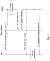
- the update procedure for the list of active set of cells is schematically illustrated in Figure 1 .
- the active set update procedure is triggered by measurement report 1a, 1b or 1c, 101 informing the network controller, e.g. a serving radio network controller SRNC, that new cells have fulfilled the criterions to be added (measurement report 1a), deleted (measurement report 1b) or replaced (measurement report 1c) in the active set.
- the measurement report 1a, 1b, 1c is sent from the user equipment to a network controller, e.g. a serving radio network controller SRNC.
- a serving radio network controller is a type of radio network controller serving a particular user equipment and manages the connections towards that user equipment. When in HS-DSCH operation, the downlink is not in soft handover.
- the network controller then performs a radio link addition 102, and sets up the required radio links by sending and receiving setup request and response 103, 104 to/from the base station.
- the network controller transmits an active set update message 105 to the user equipment.
- the user equipment When the user equipment has received the active set update from the network controller, it prepares 106 a processing, i.e. it reads the message and applies the new configuration, e.g. adds or deletes a radio link.
- the user equipment sends an active set update complete message 107 to the network controller confirming that the active set update was complete.
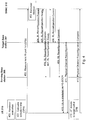
- the signalling sequence for a (regular) HSCC procedure for hard handover is schematically shown in a combined flow and signalling diagram in Figure 2 .
- the user equipment performs a handover evaluation 200 to determine whether a handover shall be performed. This is triggered by a neighbour cell, target cell, being stronger than of the current cell, serving cell.
- a measurement report 1d is sent 201 from the user equipment to the network controller, e.g. the serving radio network controller (SRNC), indicating that another cell in the list of active set of cells has become the strongest one.
- the network controller e.g. the serving radio network controller (SRNC)
- the measurement report 1d is triggered to be sent from the user equipment when the measured common pilot channel level (CPICH) of the target cell is stronger than the serving cell by a certain hysteresis for a given time, governed by a parameter Ttrig1d (time to trigger measurement report 1d).
- CPICH common pilot channel level
- T cc Ttrig 1 d + T Uu + 2 * T lub + T ActivationTime
- the network controller When the network controller receives the measurement report 1d indicating the existence of this stronger cell, the network can take the decision to change the serving cell, i.e. it takes a handover decision 202.
- the network controller configures the source and target base stations (shown as only one base station in figure 2 ) with the new configuration, and the network controller also configures the lub transport bearer.
- the network controller sends a radio link reconfiguration prepare message 203 to the base stations, and receives in return a radio link reconfiguration ready message 204 when the reconfiguration is ready.
- the network controller calculates the activation time 205 for the new configuration in case the switch to the new configuration is a synchronized procedure, meaning that the user equipment and the network controller shall move to the new configuration at the same time.
- the calculated activation time is relative to a connection frame number (CFN).
- An offset is needed to cover for the time it takes to transmit the reconfiguration commit messages 206 to both the user equipment and the base stations.
- the network controller sends a physical channel reconfiguration message 207 to the user equipment.
- the user equipment prepares a processing 208, i.e. it reads the message from the network controller and executes the handover 209, i.e. applies the new configuration, e.g. adds or deletes a radio link for the handover.
- the user equipment may send a physical channel reconfiguration complete message 210 to the network controller.
- HS-DSCH serving cell change procedure 3GPP DRAFT; R2-081901 discloses a HS-DSCH cell change procedure, wherein the mobile terminal transmits a measurement report to the network controller and moves to the target cell after a preconfigured delay and starts receiving data from the target base station.
- This HS-DSCH cell change procedure has drawbacks for a mobile terminal traveling at high speed where the link quality of the serving cell may degrade before the cell change procedure is completed so that the reconfiguration message would not reach the terminal risking an ongoing call to be dropped.
- WO 99/23847 A1 in turn discloses the transmission of an offset from a base station to a mobile terminal for simplifying the detection of neighbouring base stations. Enhancements to the HS-DSCH serving cell change procedure are consequently required regarding radio protocol procedures and structures, lub/lur protocols and user equipment, base station and radio resource management (RRM) performance requirements.
- RRM radio resource management
- a method in a user equipment for setting up an activation time of a high speed downlink shared channel cell change of the user equipment from a serving cell to a target cell in a wireless communications network After receiving a timing offset from a network controller through broadcast or dedicated signalling at call setup, the user equipment calculates a high speed downlink shared channel cell change activation time based on the timing offset, the activation time indicating when the user equipment can move to the target cell. The user equipment then transmits the calculated activation time to the network controller. Then the user equipment receives an approval of the high speed downlink shared channel cell change from the network controller. The user equipment will then move from the serving cell to the target cell at the activation time if it has received the approval.
- a method in a network controller for setting up an activation time of a high speed downlink shared channel cell change of a user equipment from a serving cell to a target cell in a wireless communications network.
- the network controller transmits a timing offset to the user equipment through broadcast or dedicated signalling at call setup and receives an activation time from the user equipment, the activation time indicating when the user equipment can move to the target cell. Then the network controller decides to move the user equipment to the target cell.
- the serving cell and the target cell are configured with the activation time.
- the network controller receives a configuration confirmation from the serving cell and the target cell, and the network controller sends an approval of the high speed downlink shared channel cell change to the user equipment.
- an arrangement in a user equipment in a wireless communication network comprising a receiver arranged to receive through broadcast or dedicated signalling at call setup a timing offset from a network controller through an interface, a processor arranged to calculate a high speed downlink shared channel cell change activation time based on the timing offset, the activation time indicating when the user equipment (310) can move to the target cell.
- the arrangement further comprises a transmitter arranged to transmit the activation time through the interface to the network controller.
- the receiver is further arranged to receive an approval of the high speed downlink shared channel cell change through the interface.
- the processor is further arranged to move from the serving cell to the target cell at the activation time if the approval has been received.
- an arrangement in a network controller is arranged to set up an activation time of a high speed downlink shared channel cell change of a user equipment from a serving cell to a target cell in a wireless communications network.
- the network controller arrangement comprises a transmitter arranged to transmit a timing offset to the user equipment through broadcast or dedicated signalling at call setup, a receiver arranged to receive an activation time from the user equipment, the activation time indicating when the user equipment (310) can move to the target cell.
- the arrangement further comprises a processor arranged to decide to move the user equipment to the target cell, and arranged to configure the serving cell and the target cell with the activation time.
- the receiver is further arranged to receive a configuration confirmation from the serving cell and the target cell
- the transmitter is further arranged to send an approval of the high speed downlink shared channel cell change to the user equipment.
- the user equipment can decide an activation time in which it will move from a source cell to a target cell it allows a synchronized operation for HS-DSCH serving cell change (HSCC).
- the synchronized operation may also be possible when the cell change command is signalled over HS-SCCH from the target base station.
- This provides an advantage of simplifying L1 (lower physical layer) termination and user plane handling over the interface between a base station and a network controller (lub).
- a further advantage is that the offset used to calculate the activation time is controlled by the network controller, and can thus be optimised based on the network configuration and delays. Another advantage of this is that it allows the network controller and user equipment to simultaneously change from source to target cell during handover.
- the present solution relates to a method and arrangement that allows synchronized operation for HS-DSCH serving cell change (HSCC) by letting the user equipment decide an activation time, i.e. a connection frame number, in which it will move from a serving cell to a target cell.
- the user equipment reports this connection frame number to the network controller in a measurement report that triggers the cell change.
- the user equipment is then allowed to move to the target cell at the connection frame number if it gets scheduled on HS-SCCH in the target cell before the connection frame number. If it does not, it stays in the source cell.
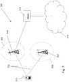
- FIG 3 shows a wireless communication network 300, using technologies such as e.g. UTRAN.
- the wireless communication network 300 comprises base stations serving cells, such as a base station 305 serving a cell 306 and a base station 307 serving a cell 308.
- the base stations 305 and 307 are radio base stations, e.g. in a radio access network, and may be referred to as NodeB.
- the base station 305 is arranged to wirelessly communicate with a user equipment 310 via e.g. radio frequency transmitters and receivers which also may be responsible for transmitting and receiving data over an air interface 312.
- the user equipment 310 may be referred to as a node device.
- the wireless communication network 300 further comprises a radio network controller 315 adapted to control the base stations 305, 307 and other base stations connected to it.
- the radio network controller 315 is the point of contact for the user equipment 310 towards the communication network 300.
- the network controller 315 is connected to a core network 316 providing services to the user equipment 310.
- the user equipment 310 moves from cell 306 towards the neighbor cell 308.
- the user equipment 310 uses cell change procedures to move from one cell to another cell when a stronger neighbor cell is detected.
- the user equipment 310 moves from one cell to another cell at an activation time.
- the user equipment 310 uses a list of active set of cells.
- the list of active set of cells comprises a list of cells to which the user equipment 310 can move from the serving cell 306.
- Figure 4 is a combined flowchart and signalling diagram illustrating an example of a cell change procedure modified to be synchronized according to embodiments of the present solution.
- the target cell 308 is preloaded with the high speed configuration during an active set update procedure (not shown). The method comprises the following steps:
- a handover evaluation is performed in the user equipment 310 because it has noticed that another cell in the list of active set of cells has become the strongest one.
- the user equipment 310 calculates the activation time based on a timing offset that is previously signalled by the network controller 315.
- the timing offset may be signalled to the user equipment 310 either by active set update, broadcast or dedicated signalling at call setup.
- the calculation of the activation time may be initiated when sending measurement report 1d during signalling procedure for HS-DSCH serving cell change is triggered in the user equipment 310.
- the activation time may e.g. be expressed as a connection frame number (CFN) in which the user equipment 310 will move from the serving cell 306 to the target cell 308.
- the calculated activation time e.g. comprised in the measurement report 1d of a handover request message, is transmitted to the network controller 315 forming a basis for a handover decision.
- the network controller 315 When the network controller 315 receives the measurement report 1d, it makes the handover decision whether to move the user equipment 310 to the target cell 308 or not. If the measurement report 1d indicates the existence of a "stronger" neighbour cell 308 than the current serving cell 306, i.e. source cell, and based on other considerations, the network controller 315 may take a decision to move the user equipment 310 to this neighbour cell, target cell 308.
- the network controller 315 sends a radio link reconfiguration prepare message to the target base station 307, to reconfigure the target base station 307 informing it also of the connection frame number in which the cell change will occur.
- the user equipment 310 listens to the target cell High-Speed Downlink Shared Channel (HS-DSCH) Shared Control Channel (HS-SCCH) until the calculated activation time is reached.
- HS-DSCH High-Speed Downlink Shared Channel
- HS-SCCH Shared Control Channel
- the target base station 307 sends a radio link reconfiguration ready message to the network controller 315 when it has performed its reconfiguration preparations.
- the network controller 315 sends a radio link reconfiguration prepare message to the serving base station 305 to reconfigure the serving base station 305 informing it also of the connection frame number in which the cell change will occur.
- the serving base station 305 sends a radio link reconfiguration ready message to the network controller 315 when it has performed its reconfiguration preparations.
- the network controller 315 sends a radio link configuration commit message to the target base station 307.
- the network controller 315 also sends a radio link configuration commit message to the serving base station 305.
- the target base station 307 When the target base station 307 has received the radio link configuration commit message it will schedule the user equipment 310 on the HS-SCCH if the message has been received before the calculated activation time.
- the user equipment 310 regards the cell change approved upon receipt of an indication of this scheduling.
- the network controller 315 may also transmit the handover confirm message over the target cell 307. This may be done by the network controller 315 transmitting a physical channel reconfiguration message to the user equipment 310.
- the user equipment 310 moves to the target cell 307 at the connection frame number. Note that this is only possible when the network controller 315 schedules the user equipment 310 on HS-SCCH in the target cell 308 or transmits the handover command in the serving cell 305 before the connection frame number. However, if the scheduling message in step 410 has been received after the activation time, the user equipment 310 remains in the serving cell 305, i.e. no cell change is performed.
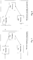
- Figure 5 is a flowchart describing the present method in the user equipment 310, for setting up an activation time of a cell change of the user equipment 310 from the serving cell 305 to the target cell 308 in a wireless communications network 300.
- the method comprises the following steps to be performed in the user equipment 310:
- the user equipment 310 receives a timing offset from a network controller 315.
- the timing offset may be received from the network controller 315 through an active set update procedure.
- the timing offset may be received from the network controller 315 through broadcast or dedicated signalling at call setup.
- the target cell 307 may be preloaded with a high speed serving cell change procedure.
- the user equipment 310 calculates a cell change activation time based on the timing offset.
- the activation time may be a connection frame number in which the user equipment 310 will move to the target cell 308.
- the user equipment 310 transmits the calculated activation time to the network controller 315.
- the activation time may be transmitted to the network controller 315 in a measurement report.
- the user equipment 310 receives an approval of the cell change from the network controller 315.
- the approval of the cell change may comprise scheduling the user equipment 310 on a high speed downlink control channel in the target cell 308.
- the user equipment 310 may be arranged to monitor a target cell 308 high speed downlink control channel until the activation time expires.
- the user equipment 310 moves from the serving cell 305 to the target cell 308 at the activation time if the approval has been received.
- the user equipment 310 may send an acknowledgement to the network controller 315.
- Figure 6 is a flowchart describing the present method in the network controller 315 for setting up an activation time of a cell change of the user equipment 310 from the serving cell 306 to the target cell 308 in a wireless communications network 300.
- the method comprises the following steps to be performed in the network controller 315:
- the network controller 315 transmits a timing offset to the user equipment 310.
- the timing offset may be transmitted to the user equipment 310 through an active set update procedure.
- the timing offset may be transmitted to the user equipment 310 through broadcast or dedicated signalling at call setup.
- the target cell 308 may be preloaded with a modified high speed serving cell change procedure.
- the network controller 315 receives an activation time from the user equipment 310.
- the activation time may be received from the user equipment 310 in a measurement report.
- the activation time may be a connection frame number in which the user equipment 310 will move to the target cell 308.
- the network controller 315 decides to move the user equipment 310 to the target cell 308.
- the network controller 315 configures the serving cell 306 and the target cell 308 with the activation time.
- the network controller 315 receives a configuration confirmation from the serving cell 306 and the target cell 308.
- the network controller 315 sends an approval of the cell change to the user equipment 310.
- the approval of the cell change may comprise scheduling the user equipment 310 on a high speed downlink control channel in the target cell 308.
- the network controller 315 may receive an acknowledgement from the user equipment 310.
- the user equipment 310 comprises a user equipment arrangement 700 as shown in Figure 7 .
- the user equipment 310 is arranged to be capable of setting up an activation time of a cell change from a serving cell 306 to a target cell 308.
- the activation time may be a connection frame number in which the user equipment 310 will move to the target cell 308.
- the user equipment arrangement 700 comprises a receiver 710 arranged to receive a timing offset from a network controller 315 through an interface 312.
- the receiver 710 may be further arranged to receive the timing offset the network controller 315 through an active set update procedure, and it may also be arranged to receive the timing offset from the network controller 315 through broadcast or dedicated signalling at call setup.
- the arrangement 700 further comprises a processor 720 arranged to calculate a cell change activation time based on the timing offset, and a transmitter 730 arranged to transmit the activation time through the interface 312 to the network controller 315.
- the transmitter 730 may be arranged to transmit the activation time to the network controller 315 in a measurement report.
- the receiver 710 is further arranged to receive an approval of the cell change through the interface 312, and the processor 720 is further arranged to move from the serving cell 306 to the target cell 308 at the activation time if the approval has been received.
- the approval of the cell change may comprise scheduling the user equipment 310 on a high speed downlink control channel in the target cell 308, and the user equipment 310 may be arranged to monitor a target cell 308 high speed downlink control channel until the activation time expires.
- the transmitter 730 may further be arranged to send an acknowledgement through the interface 312 to the network controller 315.
- the target cell 307 may be preloaded with a high speed serving cell change procedure.
- the network controller 315 comprises a network controller arrangement 800 as shown in Figure 8 .
- the network controller 315 is arranged to set up an activation time of a cell change of a user equipment 310 from a serving cell 306 to a target cell 308 in a wireless communications network 300.
- the network controller arrangement 800 comprises a transmitter 810 arranged to transmit a timing offset to the user equipment 310.
- the transmitter 810 may further be arranged to transmit the timing offset to the user equipment 310 through an active set update procedure, and the transmitter 810 may further be arranged to transmit the timing offset to the user equipment 310 through broadcast or dedicated signalling at call setup.
- the arrangement 800 further comprises a receiver 820 arranged to receive an activation time from the user equipment 310.
- the activation time may be a connection frame number in which the user equipment 310 will move to the target cell 308.
- the network controller arrangement 800 further comprises a processor 830 arranged to decide to move the user equipment 310 to the target cell 308 and arranged to configure the serving cell 306 and the target cell 308 with the activation time.
- the receiver 810 is further arranged to receive a configuration confirmation from the serving cell 306 and the target cell 308.
- the transmitter 810 may be further arranged to send an approval of the cell change to the user equipment 310.
- the approval of the cell change may comprise scheduling the user equipment 310 on a high speed downlink control channel in the target cell 308.
- the receiver 820 may be further arranged to receive an acknowledgement from the user equipment 310.
- the target cell 308 may be preloaded with a modified high speed serving cell change procedure.
- the present mechanism for setting up an activation time of a cell change from a serving cell 306 to a target cell 308 in a wireless communication network 300 may be implemented through one or more processors, such as a processor 720 in the user equipment arrangement 700 depicted in Figure 7 or a processor 830 in the network controller arrangement 800 depicted in Figure 8 , together with computer program code for performing the functions of the present solution.
- the program code mentioned above may also be provided as a computer program product, for instance in the form of a data carrier carrying computer program code for performing the present solution when being loaded into the user equipment 310 and/or network controller 315.
- One such carrier may be in the form of a CD ROM disc. It is however feasible with other data carriers such as a memory stick.
- the computer program code can furthermore be provided as pure program code on a server and downloaded to the user equipment 310 and/or network controller 315 remotely.
- An advantage with embodiments of the present solution is that the HSCC procedure may be synchronized, also when the cell change command is signalled over HS-SCCH from the target base station 307. This simplifies L1 termination and user plane handling over lub.
Landscapes
- Engineering & Computer Science (AREA)
- Computer Networks & Wireless Communication (AREA)
- Signal Processing (AREA)
- Mobile Radio Communication Systems (AREA)
Claims (26)
- Procédé mis en oeuvre par un équipement utilisateur (310) afin de mettre en place un temps d'activation d'un changement de cellule de canal partagé de liaison descendante à grande vitesse de l'équipement utilisateur (310) depuis une cellule de service (305) vers une cellule cible (308) dans un réseau de communications sans fil (300),
le procédé comprenant les étapes suivantes :la réception (501) d'un décalage de synchronisation depuis un contrôleur de réseau (315) par diffusion ou signalement dédié lors de l'établissement de l'appel ;le calcul (502) d'un temps d'activation de changement de cellule de canal partagé de liaison descendante à grande vitesse sur la base du décalage de synchronisation, le temps d'activation indiquant le moment où l'équipement utilisateur (310) se déplacera vers la cellule cible (308) ;la transmission (503) du temps d'activation calculé au contrôleur de réseau (315) ;la réception (504) d'une approbation du changement de cellule de canal partagé de liaison descendante à grande vitesse depuis le contrôleur de réseau (315) ; etle déplacement (505) depuis la cellule de service (306) vers la cellule cible (308) lors du temps d'activation si l'approbation a été reçue. - Procédé selon la revendication 1, dans lequel le procédé comprend en outre l'étape consistant à envoyer (506) un accusé de réception au contrôleur de réseau (315).
- Procédé selon l'une quelconque des revendications 1 à 2, dans lequel
le temps d'activation est un numéro de trame de connexion dans lequel l'équipement utilisateur (310) se déplacera vers la cellule cible (308). - Procédé selon l'une quelconque des revendications 1 à 3, dans lequel
l'approbation du changement de cellule comprend la programmation de l'équipement utilisateur (310) sur un canal de commande de liaison descendante à grande vitesse dans la cellule cible (308). - Procédé selon l'une quelconque des revendications 1 à 4, dans lequel
le procédé comprend en outre l'étape consistant à surveiller un canal de commande de liaison descendante à grande vitesse de la cellule cible (308) jusqu'à ce que le temps d'activation expire. - Procédé selon l'une quelconque des revendications 1 à 5, dans lequel le procédé comprend en outre l'étape consistant à transmettre (503) le temps d'activation au contrôleur de réseau (315) dans un rapport de mesure.
- Procédé selon l'une quelconque des revendications 1 à 6, dans lequel
la cellule cible (307) est préchargée avec une procédure de changement de cellule de service à grande vitesse. - Procédé mis en oeuvre par un contrôleur de réseau (315) afin de mettre en place un temps d'activation d'un changement de cellule de canal partagé de liaison descendante à grande vitesse d'un équipement utilisateur (310) depuis une cellule de service (306) vers une cellule cible (308) dans un réseau de communications sans fil (300),
le procédé comprenant les étapes suivantes :la transmission (601) d'un décalage de synchronisation à l'équipement utilisateur (310) par diffusion ou signalement dédié lors de l'établissement de l'appel ;la réception (602) d'un temps d'activation depuis l'équipement utilisateur (310), le temps d'activation indiquant le moment où l'équipement utilisateur (310) se déplacera vers la cellule cible (308) ;la décision (603) de déplacer l'équipement utilisateur (310) vers la cellule cible (308) ;la configuration (604) de la cellule de service (306) et de la cellule cible (308) avec le temps d'activation ;la réception (605) d'une confirmation de configuration depuis la cellule de service (306) et la cellule cible (308) ; etl'envoi (606) d'une approbation du changement de cellule de canal partagé de liaison descendante à grande vitesse à l'équipement utilisateur (310). - Procédé selon la revendication 8, dans lequel le procédé comprend en outre l'étape consistant à recevoir (607) un accusé de réception depuis l'équipement utilisateur (310).
- Procédé selon l'une quelconque des revendications 8 à 9, dans lequel
le temps d'activation est un numéro de trame de connexion dans lequel l'équipement utilisateur (310) se déplacera vers la cellule cible (308). - Procédé selon l'une quelconque des revendications 8 à 10, dans lequel
l'approbation du changement de cellule de canal partagé de liaison descendante à grande vitesse comprend la programmation de l'équipement utilisateur (310) sur un canal de commande de liaison descendante à grande vitesse dans la cellule cible (308). - Procédé selon l'une quelconque des revendications 8 à 11, dans lequel le procédé comprend en outre l'étape consistant à recevoir (602) le temps d'activation depuis l'équipement utilisateur (310) dans un rapport de mesure.
- Procédé selon l'une quelconque des revendications 8 à 12, dans lequel
la cellule cible (308) est préchargée avec une procédure de changement de cellule de service à grande vitesse modifiée. - Agencement (700) d'un équipement utilisateur (310) pouvant fonctionner dans un réseau de communications sans fil (300) dans lequel l'équipement utilisateur (310) est conçu pour mettre en place un temps d'activation d'un changement de cellule de canal partagé de liaison descendante à grande vitesse depuis une cellule de service (306) vers une cellule cible (308), l'agencement d'équipement utilisateur (700) comprend :un récepteur (710) conçu pour recevoir par diffusion ou signalement dédié lors de l'établissement de l'appel, un décalage de synchronisation depuis un contrôleur de réseau (315) à travers une interface (312) ;un processeur (720) conçu pour calculer un temps d'activation de changement de cellule de canal partagé de liaison descendante à grande vitesse sur la base du décalage de synchronisation, le temps d'activation indiquant le moment où l'équipement utilisateur (310) se déplacera vers la cellule cible (308) ;un émetteur (730) conçu pour transmettre le temps d'activation calculé à travers l'interface (312) au contrôleur de réseau (315) ;le récepteur (710) est en outre conçu pour recevoir une approbation du changement de cellule de canal partagé de liaison descendante à grande vitesse à travers l'interface (312) ; etle processeur (720) est en outre conçu pour déplacer l'équipement utilisateur depuis la cellule de service (306) vers la cellule cible (308) lors du temps d'activation si l'approbation a été reçue.
- Agencement (700) selon la revendication 14, dans lequel l'émetteur (730) est en outre conçu pour envoyer un accusé de réception à travers l'interface (312) au contrôleur de réseau (315).
- Agencement (700) selon l'une quelconque des revendications 14 à 15, dans lequel
le temps d'activation est un numéro de trame de connexion dans lequel l'équipement utilisateur (310) se déplacera vers la cellule cible (308). - Agencement (700) selon l'une quelconque des revendications 14 à 16, dans lequel
l'approbation du changement de cellule de canal partagé de liaison descendante à grande vitesse comprend la programmation de l'équipement utilisateur (310) sur un canal de commande de liaison descendante à grande vitesse dans la cellule cible (308). - Agencement (700) selon l'une quelconque des revendications 14 à 17, dans lequel
l'équipement utilisateur (310) est conçu pour surveiller un canal de commande de liaison descendante à grande vitesse de la cellule cible (308) jusqu'à ce que le temps d'activation expire. - Agencement (700) selon l'une quelconque des revendications 14 à 18, dans lequel l'émetteur (730) est conçu pour transmettre le temps d'activation au contrôleur de réseau (315) dans un rapport de mesure.
- Agencement (700) selon l'une quelconque des revendications 14 à 19, dans lequel
la cellule cible (307) est préchargée avec une procédure de changement de cellule de service à grande vitesse. - Agencement de contrôleur de réseau (800) dans lequel un contrôleur de réseau (315) est conçu pour mettre en place un temps d'activation d'un changement de cellule de canal partagé de liaison descendante à grande vitesse d'un équipement utilisateur (310) depuis une cellule de service (306) vers une cellule cible (308) dans un réseau de communications sans fil (300),
l'agencement de contrôleur de réseau (800) comprend :un émetteur (810) conçu pour transmettre un décalage de synchronisation à l'équipement utilisateur (310) par diffusion ou signalement dédié lors de l'établissement de l'appel ;un récepteur (820) conçu pour recevoir un temps d'activation depuis l'équipement utilisateur (310), le temps d'activation indiquant le moment où l'équipement utilisateur (310) se déplacera vers la cellule cible (308) ;un processeur (830) conçu pour décider de déplacer l'équipement utilisateur (310) vers la cellule cible (308) et conçu pour configurer la cellule de service (306) et la cellule cible (308) avec le temps d'activation ;le récepteur (820) est en outre conçu pour recevoir une confirmation de configuration depuis la cellule de service (306) et la cellule cible (308) ; etl'émetteur (810) est en outre conçu pour envoyer une approbation du changement de cellule de canal partagé de liaison descendante à grande vitesse à l'équipement utilisateur (310). - Agencement (800) selon la revendication 21, dans lequel le récepteur (820) est en outre conçu pour recevoir un accusé de réception depuis l'équipement utilisateur (310).
- Agencement (800) selon l'une quelconque des revendications 21 à 22, dans lequel
le temps d'activation est un numéro de trame de connexion dans lequel l'équipement utilisateur (310) se déplacera vers la cellule cible (308). - Agencement (800) selon l'une quelconque des revendications 21 à 23, dans lequel
l'approbation du changement de cellule de canal partagé de liaison descendante à grande vitesse comprend la programmation de l'équipement utilisateur (310) sur un canal de commande de liaison descendante à grande vitesse dans la cellule cible (308). - Agencement (800) selon l'une quelconque des revendications 21 à 24, dans lequel le récepteur (820) est conçu pour recevoir le temps d'activation depuis l'équipement utilisateur (310) dans un rapport de mesure.
- Agencement (800) selon l'une quelconque des revendications 21 à 25, dans lequel
la cellule cible (308) est préchargée avec une procédure de changement de cellule de service à grande vitesse modifiée.
Applications Claiming Priority (2)
| Application Number | Priority Date | Filing Date | Title |
|---|---|---|---|
| US4128308P | 2008-04-01 | 2008-04-01 | |
| EP09727806.3A EP2266349B1 (fr) | 2008-04-01 | 2009-03-19 | Temps d'activation pour changement de cellule de desserte à grande vitesse basé sur la cible |
Related Parent Applications (3)
| Application Number | Title | Priority Date | Filing Date |
|---|---|---|---|
| EP09727806.3 Division | 2009-03-19 | ||
| EP09727806.3A Division EP2266349B1 (fr) | 2008-04-01 | 2009-03-19 | Temps d'activation pour changement de cellule de desserte à grande vitesse basé sur la cible |
| EP09727806.3A Division-Into EP2266349B1 (fr) | 2008-04-01 | 2009-03-19 | Temps d'activation pour changement de cellule de desserte à grande vitesse basé sur la cible |
Publications (2)
| Publication Number | Publication Date |
|---|---|
| EP2375823A1 EP2375823A1 (fr) | 2011-10-12 |
| EP2375823B1 true EP2375823B1 (fr) | 2018-01-03 |
Family
ID=40791115
Family Applications (2)
| Application Number | Title | Priority Date | Filing Date |
|---|---|---|---|
| EP10196490.6A Active EP2375823B1 (fr) | 2008-04-01 | 2009-03-19 | Temps d'activation pour un changement de cellule de service à grande vitesse |
| EP09727806.3A Active EP2266349B1 (fr) | 2008-04-01 | 2009-03-19 | Temps d'activation pour changement de cellule de desserte à grande vitesse basé sur la cible |
Family Applications After (1)
| Application Number | Title | Priority Date | Filing Date |
|---|---|---|---|
| EP09727806.3A Active EP2266349B1 (fr) | 2008-04-01 | 2009-03-19 | Temps d'activation pour changement de cellule de desserte à grande vitesse basé sur la cible |
Country Status (11)
| Country | Link |
|---|---|
| US (3) | US8606277B2 (fr) |
| EP (2) | EP2375823B1 (fr) |
| JP (1) | JP5367808B2 (fr) |
| CN (1) | CN101981971B (fr) |
| AU (1) | AU2009232422B2 (fr) |
| DK (1) | DK2266349T3 (fr) |
| ES (2) | ES2663297T3 (fr) |
| HU (1) | HUE031926T2 (fr) |
| IL (1) | IL208448A (fr) |
| RU (1) | RU2488979C2 (fr) |
| WO (1) | WO2009123545A1 (fr) |
Families Citing this family (6)
| Publication number | Priority date | Publication date | Assignee | Title |
|---|---|---|---|---|
| US8126463B2 (en) * | 2007-09-12 | 2012-02-28 | Kabushiki Kaisha Toshiba | Mobile communication system, base station control apparatus, mobile terminal and method for controlling handover |
| JP5367808B2 (ja) * | 2008-04-01 | 2013-12-11 | テレフオンアクチーボラゲット エル エム エリクソン(パブル) | ターゲットベースの高速在圏セル変更のためのアクティベーション時間 |
| EP2522178A1 (fr) * | 2010-01-08 | 2012-11-14 | InterDigital Patent Holdings, Inc. | Évaluation et indication de mesures de la mobilité de n uds h(e)nb sortants et de la mobilité inter-n uds h(e)nb en mode connecté |
| US8565188B2 (en) * | 2010-12-21 | 2013-10-22 | Qualcomm Incorporated | Minimizing call drops during a serving cell change |
| US20150071089A1 (en) * | 2013-09-06 | 2015-03-12 | Qualcomm Incorporated | Devices and methods for decreasing awake state durations in access terminals operating in a slotted idle mode |
| EP2854451A1 (fr) * | 2013-09-25 | 2015-04-01 | Alcatel Lucent | Station de base pour le transfert intercellulaire entre petites cellules |
Family Cites Families (33)
| Publication number | Priority date | Publication date | Assignee | Title |
|---|---|---|---|---|
| NZ243730A (en) * | 1991-08-01 | 1995-04-27 | Ericsson Ge Mobile Communicat | Mobile radio; access to base station on digital multiple access control channel |
| US5949769A (en) * | 1995-10-10 | 1999-09-07 | Sicom, Inc. | Multirate local multipoint data distribution system |
| US6041088A (en) * | 1996-10-23 | 2000-03-21 | Sicom, Inc. | Rapid synchronization for communication systems |
| US6101175A (en) * | 1997-10-31 | 2000-08-08 | Motorola, Inc. | Method and apparatus for handoff within a communication system |
| US7876729B1 (en) * | 1998-07-20 | 2011-01-25 | Qualcomm Incorporated | Intersystem base station handover |
| EP1289328A1 (fr) * | 2001-08-28 | 2003-03-05 | Lucent Technologies Inc. | Procédé pour la transmission d'information de commande dans un réseau de télécommunications sans fil et appareil correspondant |
| KR100487245B1 (ko) * | 2001-11-28 | 2005-05-03 | 삼성전자주식회사 | 고속 순방향 패킷 접속 방식을 사용하는 이동 통신시스템에서압축 모드에 따른 전송 불능 구간을 최소화하는장치 및 방법 |
| KR100832117B1 (ko) * | 2002-02-17 | 2008-05-27 | 삼성전자주식회사 | 고속 순방향 패킷 접속 방식을 사용하는 이동통신 시스템에서 역방향 송신전력 오프셋 정보를 송수신하는 장치 및 방법 |
| EP1432262A1 (fr) * | 2002-12-20 | 2004-06-23 | Matsushita Electric Industrial Co., Ltd. | Conservation de contexte de protocole dans des systèmes de communication mobiles |
| KR100640344B1 (ko) * | 2003-03-08 | 2006-10-30 | 삼성전자주식회사 | 광대역 무선 접속 통신 시스템의 기지국에서 핸드오버 시스템 및 방법 |
| DE60319503T2 (de) * | 2003-04-11 | 2009-05-28 | Telefonaktiebolaget Lm Ericsson (Publ) | Verfahren zur Synchronisierung in einem mobilen Funkendgerät |
| EP1618748B1 (fr) * | 2003-04-23 | 2016-04-13 | QUALCOMM Incorporated | Procedes et appareil permettant d'ameliorer les performances de systemes de communication sans fil |
| US7039407B2 (en) * | 2003-08-14 | 2006-05-02 | Nokia Corporation | Method and system for determining a value of a first counter of a wireless communication system serving a user station which moves at a time of handover |
| EP1507422A1 (fr) * | 2003-08-14 | 2005-02-16 | Matsushita Electric Industrial Co., Ltd. | Selection d'une station de base pendant un transfert souple |
| EP1507433B1 (fr) * | 2003-08-15 | 2013-02-13 | Research In Motion Limited | Procédé et dispositif pour déterminer le temps d'activation de chiffrement pour un appareil utilisateur dans un système de communication UMTS |
| DE602004000677T2 (de) * | 2003-08-15 | 2007-05-10 | Research In Motion Ltd., Waterloo | Bestimmung der Aktivierungszeit für eine Aufwärtsrichtungsverschlüsselung in einem UMTS Teilnehmergerät |
| US7184792B2 (en) * | 2004-02-10 | 2007-02-27 | Qualcomm Incorporated | Delayed data transmission in a wireless communication system after physical layer reconfiguration |
| EP1592275B1 (fr) * | 2004-04-29 | 2006-06-21 | Matsushita Electric Industrial Co., Ltd. | Déplacement aussi partiellement d'une fonctionnalité de gestion de ressources radio d'un premier station de base à un autre dans un réseau d'accès radio distribué |
| US7218936B2 (en) * | 2004-07-07 | 2007-05-15 | Nokia Corporation | Transmitting of cell management information in a cellular communication network |
| TWI288572B (en) * | 2004-08-04 | 2007-10-11 | Benq Corp | Mobile unit and method for which to re-select a serving base station |
| US7711367B2 (en) * | 2004-10-29 | 2010-05-04 | Alcatel-Lucent Usa Inc. | Fast handover with reduced service interruption for high speed data channels in a wireless system |
| WO2006114692A2 (fr) * | 2005-04-25 | 2006-11-02 | Nokia Corporation | Procede, appareil et programme informatique assurant le changement de cellule d'acces de paquets de liaison descendante a grande vitesse (hsdpa) sans accuse de reception rrc |
| KR100770838B1 (ko) * | 2005-05-11 | 2007-10-26 | 삼성전자주식회사 | 이동통신시스템에서의 핸드오버 방법과 그를 위한 이동통신시스템의 무선 네트워크 제어기 |
| US7796991B2 (en) * | 2005-06-15 | 2010-09-14 | Juho Pirskanen | RRC signalling for fast HS-DSCH serving cell change |
| GB2429877B (en) * | 2005-09-06 | 2008-02-06 | Motorola Inc | Radio link handover in a cellular communication system |
| US20070072621A1 (en) * | 2005-09-27 | 2007-03-29 | Mukkavilli Krishna K | Position location using transmitters with timing offset |
| US9354297B2 (en) * | 2005-09-27 | 2016-05-31 | Qualcomm Incorporated | Position location using phase-adjusted transmitters |
| EP1938640A1 (fr) * | 2005-10-17 | 2008-07-02 | TELEFONAKTIEBOLAGET LM ERICSSON (publ) | Procede permettant de realiser un transfert dans un systeme de telecommunication cellulaire a commutation par paquets |
| EP1781057A1 (fr) * | 2005-10-26 | 2007-05-02 | Matsushita Electric Industrial Co., Ltd. | Établissement rapide d'un support radio dans un système de communication |
| TWM355515U (en) * | 2007-12-31 | 2009-04-21 | Interdigital Patent Holdings | Apparatus for radio link synchronization and power control in CELL_FACH and idle mode |
| JP5367808B2 (ja) * | 2008-04-01 | 2013-12-11 | テレフオンアクチーボラゲット エル エム エリクソン(パブル) | ターゲットベースの高速在圏セル変更のためのアクティベーション時間 |
| US7876792B2 (en) | 2008-10-31 | 2011-01-25 | Alcatel Lucent | Network element clocking accuracy and stability monitoring over a packet-switched network |
| US8520632B2 (en) * | 2008-12-29 | 2013-08-27 | Qualcomm Incorporated | Method and apparatus for synchronization during a handover failure in a wireless communication system |
-
2009
- 2009-03-19 JP JP2011502897A patent/JP5367808B2/ja active Active
- 2009-03-19 HU HUE09727806A patent/HUE031926T2/en unknown
- 2009-03-19 AU AU2009232422A patent/AU2009232422B2/en active Active
- 2009-03-19 DK DK09727806.3T patent/DK2266349T3/en active
- 2009-03-19 WO PCT/SE2009/050285 patent/WO2009123545A1/fr active Application Filing
- 2009-03-19 ES ES10196490.6T patent/ES2663297T3/es active Active
- 2009-03-19 CN CN2009801123947A patent/CN101981971B/zh active Active
- 2009-03-19 US US12/935,941 patent/US8606277B2/en active Active
- 2009-03-19 EP EP10196490.6A patent/EP2375823B1/fr active Active
- 2009-03-19 ES ES09727806.3T patent/ES2616514T3/es active Active
- 2009-03-19 EP EP09727806.3A patent/EP2266349B1/fr active Active
- 2009-03-19 RU RU2010144518/07A patent/RU2488979C2/ru active
-
2010
- 2010-10-03 IL IL208448A patent/IL208448A/en active IP Right Grant
-
2013
- 2013-12-09 US US14/101,249 patent/US9185624B2/en active Active
-
2015
- 2015-09-23 US US14/862,938 patent/US9961597B2/en active Active
Non-Patent Citations (1)
| Title |
|---|
| None * |
Also Published As
| Publication number | Publication date |
|---|---|
| AU2009232422A1 (en) | 2009-10-08 |
| ES2616514T3 (es) | 2017-06-13 |
| IL208448A0 (en) | 2010-12-30 |
| RU2488979C2 (ru) | 2013-07-27 |
| US8606277B2 (en) | 2013-12-10 |
| US20140087737A1 (en) | 2014-03-27 |
| ES2663297T3 (es) | 2018-04-11 |
| IL208448A (en) | 2014-04-30 |
| CN101981971A (zh) | 2011-02-23 |
| EP2266349B1 (fr) | 2016-11-23 |
| JP2011517204A (ja) | 2011-05-26 |
| AU2009232422B2 (en) | 2014-05-01 |
| DK2266349T3 (en) | 2017-02-20 |
| EP2266349A1 (fr) | 2010-12-29 |
| HUE031926T2 (en) | 2017-08-28 |
| WO2009123545A1 (fr) | 2009-10-08 |
| CN101981971B (zh) | 2013-11-27 |
| US20110028151A1 (en) | 2011-02-03 |
| JP5367808B2 (ja) | 2013-12-11 |
| RU2010144518A (ru) | 2012-05-10 |
| US20160014652A1 (en) | 2016-01-14 |
| US9185624B2 (en) | 2015-11-10 |
| US9961597B2 (en) | 2018-05-01 |
| EP2375823A1 (fr) | 2011-10-12 |
Similar Documents
| Publication | Publication Date | Title |
|---|---|---|
| US9462514B2 (en) | Configuration of HS-DSCH serving cell change improvements | |
| EP2241125B1 (fr) | Gestion automatique de liste de relations de voisins inter-technologie d'accès radio/interfréquence | |
| US9961597B2 (en) | Activation time for target based high speed serving cell change | |
| US7197307B2 (en) | Hard handover method and controller | |
| KR100791156B1 (ko) | 이동국으로 압축 모드 파라미터를 시그널링하는 방법 | |
| CN106416363B (zh) | 用于在多小区无线通信网络中调整小区更改时间的方法 |
Legal Events
| Date | Code | Title | Description |
|---|---|---|---|
| PUAI | Public reference made under article 153(3) epc to a published international application that has entered the european phase |
Free format text: ORIGINAL CODE: 0009012 |
|
| 17P | Request for examination filed |
Effective date: 20101222 |
|
| AC | Divisional application: reference to earlier application |
Ref document number: 2266349 Country of ref document: EP Kind code of ref document: P |
|
| AK | Designated contracting states |
Kind code of ref document: A1 Designated state(s): AT BE BG CH CY CZ DE DK EE ES FI FR GB GR HR HU IE IS IT LI LT LU LV MC MK MT NL NO PL PT RO SE SI SK TR |
|
| AX | Request for extension of the european patent |
Extension state: AL BA RS |
|
| 17Q | First examination report despatched |
Effective date: 20161021 |
|
| GRAP | Despatch of communication of intention to grant a patent |
Free format text: ORIGINAL CODE: EPIDOSNIGR1 |
|
| INTG | Intention to grant announced |
Effective date: 20170726 |
|
| GRAS | Grant fee paid |
Free format text: ORIGINAL CODE: EPIDOSNIGR3 |
|
| GRAA | (expected) grant |
Free format text: ORIGINAL CODE: 0009210 |
|
| AC | Divisional application: reference to earlier application |
Ref document number: 2266349 Country of ref document: EP Kind code of ref document: P |
|
| AK | Designated contracting states |
Kind code of ref document: B1 Designated state(s): AT BE BG CH CY CZ DE DK EE ES FI FR GB GR HR HU IE IS IT LI LT LU LV MC MK MT NL NO PL PT RO SE SI SK TR |
|
| REG | Reference to a national code |
Ref country code: GB Ref legal event code: FG4D |
|
| REG | Reference to a national code |
Ref country code: CH Ref legal event code: EP Ref country code: AT Ref legal event code: REF Ref document number: 961318 Country of ref document: AT Kind code of ref document: T Effective date: 20180115 |
|
| REG | Reference to a national code |
Ref country code: IE Ref legal event code: FG4D |
|
| REG | Reference to a national code |
Ref country code: CH Ref legal event code: NV Representative=s name: ISLER AND PEDRAZZINI AG, CH |
|
| REG | Reference to a national code |
Ref country code: DE Ref legal event code: R096 Ref document number: 602009050268 Country of ref document: DE |
|
| REG | Reference to a national code |
Ref country code: SE Ref legal event code: TRGR |
|
| REG | Reference to a national code |
Ref country code: FR Ref legal event code: PLFP Year of fee payment: 10 |
|
| REG | Reference to a national code |
Ref country code: ES Ref legal event code: FG2A Ref document number: 2663297 Country of ref document: ES Kind code of ref document: T3 Effective date: 20180411 Ref country code: NL Ref legal event code: FP |
|
| REG | Reference to a national code |
Ref country code: LT Ref legal event code: MG4D |
|
| PG25 | Lapsed in a contracting state [announced via postgrant information from national office to epo] |
Ref country code: HR Free format text: LAPSE BECAUSE OF FAILURE TO SUBMIT A TRANSLATION OF THE DESCRIPTION OR TO PAY THE FEE WITHIN THE PRESCRIBED TIME-LIMIT Effective date: 20180103 Ref country code: NO Free format text: LAPSE BECAUSE OF FAILURE TO SUBMIT A TRANSLATION OF THE DESCRIPTION OR TO PAY THE FEE WITHIN THE PRESCRIBED TIME-LIMIT Effective date: 20180403 Ref country code: LT Free format text: LAPSE BECAUSE OF FAILURE TO SUBMIT A TRANSLATION OF THE DESCRIPTION OR TO PAY THE FEE WITHIN THE PRESCRIBED TIME-LIMIT Effective date: 20180103 Ref country code: CY Free format text: LAPSE BECAUSE OF FAILURE TO SUBMIT A TRANSLATION OF THE DESCRIPTION OR TO PAY THE FEE WITHIN THE PRESCRIBED TIME-LIMIT Effective date: 20180103 |
|
| PG25 | Lapsed in a contracting state [announced via postgrant information from national office to epo] |
Ref country code: LV Free format text: LAPSE BECAUSE OF FAILURE TO SUBMIT A TRANSLATION OF THE DESCRIPTION OR TO PAY THE FEE WITHIN THE PRESCRIBED TIME-LIMIT Effective date: 20180103 Ref country code: IS Free format text: LAPSE BECAUSE OF FAILURE TO SUBMIT A TRANSLATION OF THE DESCRIPTION OR TO PAY THE FEE WITHIN THE PRESCRIBED TIME-LIMIT Effective date: 20180503 Ref country code: PL Free format text: LAPSE BECAUSE OF FAILURE TO SUBMIT A TRANSLATION OF THE DESCRIPTION OR TO PAY THE FEE WITHIN THE PRESCRIBED TIME-LIMIT Effective date: 20180103 Ref country code: BG Free format text: LAPSE BECAUSE OF FAILURE TO SUBMIT A TRANSLATION OF THE DESCRIPTION OR TO PAY THE FEE WITHIN THE PRESCRIBED TIME-LIMIT Effective date: 20180403 |
|
| REG | Reference to a national code |
Ref country code: GR Ref legal event code: EP Ref document number: 20180400683 Country of ref document: GR Effective date: 20180829 |
|
| REG | Reference to a national code |
Ref country code: DE Ref legal event code: R097 Ref document number: 602009050268 Country of ref document: DE |
|
| PG25 | Lapsed in a contracting state [announced via postgrant information from national office to epo] |
Ref country code: RO Free format text: LAPSE BECAUSE OF FAILURE TO SUBMIT A TRANSLATION OF THE DESCRIPTION OR TO PAY THE FEE WITHIN THE PRESCRIBED TIME-LIMIT Effective date: 20180103 Ref country code: EE Free format text: LAPSE BECAUSE OF FAILURE TO SUBMIT A TRANSLATION OF THE DESCRIPTION OR TO PAY THE FEE WITHIN THE PRESCRIBED TIME-LIMIT Effective date: 20180103 |
|
| PLBE | No opposition filed within time limit |
Free format text: ORIGINAL CODE: 0009261 |
|
| STAA | Information on the status of an ep patent application or granted ep patent |
Free format text: STATUS: NO OPPOSITION FILED WITHIN TIME LIMIT |
|
| PG25 | Lapsed in a contracting state [announced via postgrant information from national office to epo] |
Ref country code: DK Free format text: LAPSE BECAUSE OF FAILURE TO SUBMIT A TRANSLATION OF THE DESCRIPTION OR TO PAY THE FEE WITHIN THE PRESCRIBED TIME-LIMIT Effective date: 20180103 Ref country code: MC Free format text: LAPSE BECAUSE OF FAILURE TO SUBMIT A TRANSLATION OF THE DESCRIPTION OR TO PAY THE FEE WITHIN THE PRESCRIBED TIME-LIMIT Effective date: 20180103 Ref country code: CZ Free format text: LAPSE BECAUSE OF FAILURE TO SUBMIT A TRANSLATION OF THE DESCRIPTION OR TO PAY THE FEE WITHIN THE PRESCRIBED TIME-LIMIT Effective date: 20180103 Ref country code: SK Free format text: LAPSE BECAUSE OF FAILURE TO SUBMIT A TRANSLATION OF THE DESCRIPTION OR TO PAY THE FEE WITHIN THE PRESCRIBED TIME-LIMIT Effective date: 20180103 |
|
| REG | Reference to a national code |
Ref country code: BE Ref legal event code: MM Effective date: 20180331 |
|
| 26N | No opposition filed |
Effective date: 20181005 |
|
| PG25 | Lapsed in a contracting state [announced via postgrant information from national office to epo] |
Ref country code: LU Free format text: LAPSE BECAUSE OF NON-PAYMENT OF DUE FEES Effective date: 20180319 |
|
| PG25 | Lapsed in a contracting state [announced via postgrant information from national office to epo] |
Ref country code: BE Free format text: LAPSE BECAUSE OF NON-PAYMENT OF DUE FEES Effective date: 20180331 Ref country code: SI Free format text: LAPSE BECAUSE OF FAILURE TO SUBMIT A TRANSLATION OF THE DESCRIPTION OR TO PAY THE FEE WITHIN THE PRESCRIBED TIME-LIMIT Effective date: 20180103 |
|
| PG25 | Lapsed in a contracting state [announced via postgrant information from national office to epo] |
Ref country code: MT Free format text: LAPSE BECAUSE OF NON-PAYMENT OF DUE FEES Effective date: 20180319 |
|
| PG25 | Lapsed in a contracting state [announced via postgrant information from national office to epo] |
Ref country code: PT Free format text: LAPSE BECAUSE OF FAILURE TO SUBMIT A TRANSLATION OF THE DESCRIPTION OR TO PAY THE FEE WITHIN THE PRESCRIBED TIME-LIMIT Effective date: 20180103 Ref country code: HU Free format text: LAPSE BECAUSE OF FAILURE TO SUBMIT A TRANSLATION OF THE DESCRIPTION OR TO PAY THE FEE WITHIN THE PRESCRIBED TIME-LIMIT; INVALID AB INITIO Effective date: 20090319 |
|
| REG | Reference to a national code |
Ref country code: AT Ref legal event code: UEP Ref document number: 961318 Country of ref document: AT Kind code of ref document: T Effective date: 20180103 |
|
| PG25 | Lapsed in a contracting state [announced via postgrant information from national office to epo] |
Ref country code: MK Free format text: LAPSE BECAUSE OF NON-PAYMENT OF DUE FEES Effective date: 20180103 |
|
| PGFP | Annual fee paid to national office [announced via postgrant information from national office to epo] |
Ref country code: IE Payment date: 20230327 Year of fee payment: 15 Ref country code: FR Payment date: 20230327 Year of fee payment: 15 Ref country code: FI Payment date: 20230327 Year of fee payment: 15 Ref country code: AT Payment date: 20230303 Year of fee payment: 15 |
|
| PGFP | Annual fee paid to national office [announced via postgrant information from national office to epo] |
Ref country code: TR Payment date: 20230306 Year of fee payment: 15 Ref country code: SE Payment date: 20230315 Year of fee payment: 15 Ref country code: IT Payment date: 20230321 Year of fee payment: 15 Ref country code: GR Payment date: 20230331 Year of fee payment: 15 Ref country code: GB Payment date: 20230327 Year of fee payment: 15 |
|
| PGFP | Annual fee paid to national office [announced via postgrant information from national office to epo] |
Ref country code: CH Payment date: 20230402 Year of fee payment: 15 |
|
| PGFP | Annual fee paid to national office [announced via postgrant information from national office to epo] |
Ref country code: NL Payment date: 20240326 Year of fee payment: 16 |
|
| PGFP | Annual fee paid to national office [announced via postgrant information from national office to epo] |
Ref country code: DE Payment date: 20240327 Year of fee payment: 16 |
|
| PGFP | Annual fee paid to national office [announced via postgrant information from national office to epo] |
Ref country code: ES Payment date: 20240401 Year of fee payment: 16 |