EP2375086A2 - Installation hydraulique - Google Patents
Installation hydraulique Download PDFInfo
- Publication number
- EP2375086A2 EP2375086A2 EP11002616A EP11002616A EP2375086A2 EP 2375086 A2 EP2375086 A2 EP 2375086A2 EP 11002616 A EP11002616 A EP 11002616A EP 11002616 A EP11002616 A EP 11002616A EP 2375086 A2 EP2375086 A2 EP 2375086A2
- Authority
- EP
- European Patent Office
- Prior art keywords
- pressure
- pressure medium
- valve
- accumulator
- consumer
- Prior art date
- Legal status (The legal status is an assumption and is not a legal conclusion. Google has not performed a legal analysis and makes no representation as to the accuracy of the status listed.)
- Withdrawn
Links
Images
Classifications
-
- F—MECHANICAL ENGINEERING; LIGHTING; HEATING; WEAPONS; BLASTING
- F15—FLUID-PRESSURE ACTUATORS; HYDRAULICS OR PNEUMATICS IN GENERAL
- F15B—SYSTEMS ACTING BY MEANS OF FLUIDS IN GENERAL; FLUID-PRESSURE ACTUATORS, e.g. SERVOMOTORS; DETAILS OF FLUID-PRESSURE SYSTEMS, NOT OTHERWISE PROVIDED FOR
- F15B1/00—Installations or systems with accumulators; Supply reservoir or sump assemblies
- F15B1/02—Installations or systems with accumulators
- F15B1/024—Installations or systems with accumulators used as a supplementary power source, e.g. to store energy in idle periods to balance pump load
Definitions
- the invention relates to a hydraulic system, in particular for a commercial vehicle or a working machine, with a pressure medium from a pressure medium container to at least one consumer-promoting pressure medium pump, a continuously adjustable directional control valve connects a pump connection with consumer connections, the consumer is connected via working lines to the directional control valve, and wherein a drainage volume flow of the pressure medium is adjustable via a throttle device.
- hydraulic systems such as drives for working machines, for example in the form of excavators, pivoting movements, which are made by hydrostatic cylinders, as well as driving movements and rotational movements, which are generated by hydrostatic rotary drives or slewing, regularly provided.
- the provision of hydraulic energy including the pressure medium supply usually take pressure medium pumps with variable displacement, which are driven by a traction motor of the working machine, for example, from a diesel internal combustion engine.
- the WO 2009/108830 A1 discloses a hydraulic drive, in particular for a slewing gear of a superstructure of an excavator.
- the hydraulic circuit comprises a pump and a hydraulic motor, which via a valve connected to the pump.
- an electro-proportionally adjustable throttle valve and a check valve to a pressure fluid reservoir is fed and returned at a renewed acceleration again over the same number of valves.
- the disadvantage are the significant pressure losses through the series connection of said valves.
- the engine displacement of the hydraulic drive for the superstructure is kept constant.
- the slewing is not available here as an adaptive braking torque applying component of the hydraulic system.
- a hydraulic drive system for driving a rotating device as exemplified in the DE 10 2007 046 696 A1 is disclosed.
- the slewing has in this case a 4-quadrant variable displacement, the absorption volume is thus adaptable to the various operating phases and allows the homogeneous transitions from the operation of the hydraulic system with the accumulator and the pressure medium pump.
- the hydraulic drive system at least in the disclosed embodiment, has no seat-tight valves which could prevent emptying of the accumulator due to leaks in the 4-quadrant variable displacement motor.
- the hydraulic builds Drive system with two variable displacement motors in the practical realization complex on.
- the present invention seeks to provide a hydraulic system for driving consumers, which works energy-efficient and is reliable in operation.
- the hydraulic system according to the invention has an energy-efficient switching construction including a directional control valve as the main control valve between the pressure medium pump and the consumer to the effect that a flow as less valves and components in a filling and emptying of the accumulator is achieved, which also the reliability of the system Operation increased.
- a accumulator charging valve is provided, whose activation in response to control pressures, in particular in response to a control pressure on the inlet side of a directional control valve, and further in response to the switching position of a throttle device, such as in the embodiment of a brake slide in the directional control valve.
- the accumulator charging valve is designed as a continuously adjustable, hydraulically actuated by the control pressures on the directional control valve.
- the accumulator charging valve is actuated via the control pressure at the directional control valve so that it is brought into an open switching position during load operation at partial load or full load by the load pressure at the consumer inlet side of the directional control valve, in which an outflow volume flow from the consumer intervenes this and the directional valve a pressure fluid store can be supplied.
- the throttle device which is preferably a brake slide or brake valve, which is preferably integrated in the directional control valve, held in an open position in the pressure medium from the consumer via the directional control valve and the throttle device in the pressure medium container, preferably in shape a tank, can flow.
- the throttle device is so far controlled independently of the switching position of a valve element of the directional control valve and held in such an acceleration operations of the consumer in an open switching position.
- the throttle device in particular a brake slide of a brake valve, which throttles the drainage volume flow, preferably completely closed.
- the accumulator charging valve remains in the position resulting from the acceleration phase and the displacement of the slewing motor preferably takes simultaneously a small value in order to ensure a minimum braking torque at the initiation of the braking operation and a steady transition to deceleration.
- the accumulator charging valve is open to the outlet side of the engine.
- an open-loop and / or closed-loop control device in which, inter alia, an algorithm for the relationship between the speed difference of the setpoint input and the configured as a turning consumer is stored, depending on the selected braking torque To choose swivel angle or the delivery volume of the adjustment such that a current storage pressure in the pressure fluid reservoir can be considered.
- a storage discharge valve opens to the pressure side of the pump and the pressure medium pump thus reduces its delivery volume at a node arranged between the directional control valve and the pressure medium pump that stored in the pressure fluid accumulator pressure medium can be entered in the direction of the consumer in the hydraulic circuit.
- This leads to an acceleration process (boost function), which relieves the pressure medium pump accordingly.
- This acceleration and the operation of the consumer with pressure fluid from the accumulator continues until a preferably provided regulator for the pressure medium pump determines a corresponding pressure drop and the delivery rate of the pressure medium pump is increased again.
- the hydraulic system can be extended to a pressure compensator function to the effect that this is connected upstream of the directional control valve and a total load adjustment of the directional control valve supplied pressure medium flow allows.
- a pressure compensator function to the effect that this is connected upstream of the directional control valve and a total load adjustment of the directional control valve supplied pressure medium flow allows.
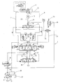
- the single figure shows a schematic representation in the manner of a hydraulic circuit diagram, relating to the hydraulic system for operating a hydraulic rotary drive for an excavator superstructure.
- the hydraulic system 1 shown in the figure is used to control and supply a hydraulic consumer 4 with a pressure medium 2, for example in the form of a conventional hydraulic oil.
- the consumer 4 is using an adjustable in their delivery pressure medium pump 5 supplied in a so-called.
- the consumer 4 is designed as a hydraulic rotary drive or slewing gear 16 whose direction of rotation is variable.
- the slewing gear 16 is intended in the embodiment shown as a drive for a so-called.
- Upper carriage of an excavator (not shown).
- other applications can be addressed here.
- the pressure medium pump 5 is driven by an internal combustion engine 17 in the manner of a diesel engine, wherein the delivery volume of the pressure medium pump 5 can be changed by a load pressure signal LS on a, the pressure medium flow controlling directional control valve 6 as the main control valve of the system 1.
- the directional control valve 6 is formed from the basic conception as a continuously adjustable 4/3-way valve, of which only an exemplary embodiment is shown in the figure and with reference to the load-sensing connection LS shown, the directional control valve 6 is a 5/3-way valve is and will be referred to as such in the following.
- the directional control valve 6 is fluidly connected to the consumer 4 with two working lines 7, 8. Parallel to the directional control valve 6, a storage charging valve 11 is inserted into the two working lines 7.8, whereby a pressure fluid accumulator 12 is rechargeable.
- the accumulator charging valve 11 is designed as a spring-centered 3/3-way valve whose movable valve element is controlled in response to control pressures xA, xB at the pilot heads of the 5/3-way valve 6. In the switching position shown in the figure, the accumulator charging valve 11 is in its blocking position, in which the consumer 4 is then depressurized.
- the control pressure at the directional control valve 6 causes the return of the consumer 4 or the outflow volume flow 9 to be able to be conducted into the pressure fluid accumulator 12 and the pressure fluid accumulator 12 charged in such a way becomes.
- This is effected via the accumulator charging valve 11, regardless of the respective direction of rotation of the consumer 4, in view of its principle symmetrical design of the associated valve element and its switching operations.
- a throttle device 10 which cooperates with the directional control valve 6, in a the flow volume flow 9 to the pressure medium tank 3 (tank) blocking position to bring. Only then is a closing pressure of a check valve 14, which is arranged between the accumulator charging valve 11 and the accumulator 12, surmountable and the accumulator 12 can be filled with pressure medium 2 from the drain volume flow 9 of the consumer 4.
- the throttle device 10 is formed as a brake valve 18 with a, integrated in a spool of the directional control valve 6 and coaxially movable independently of the switching position of the spool brake slide.
- a detailed description of the function and structure of such a throttle device 10 is exemplary in the post-published prior application DE 10 2009 058 371 the copyright holder.
- the brake valve 18 represents a, the drain volume flow 9 of the pressure medium 2 from the consumer 4 very stable controlling throttle device 10.
- a storage discharge valve 13 is still present within the system 1, which forms a directional valve controlled by the load pressure LS on the directional control valve 6.
- the storage discharge valve 13 establishes a fluid-conducting connection between a node 19 and a node 21.
- the node 19 is arranged in a pressure medium line 20 between the check valve 14 and the accumulator 12 and the node 21 is disposed between a check valve 22 in a pressure medium line upstream of the pressure medium pump 5 and the pump port P to the directional control valve 6.
- the load pressure LS increases at the directional control valve 6 and thereby leads to an open switching state of the valve element of the accumulator discharge valve 13 against the force of its adjusting spring 23, which seeks to keep the valve element of the accumulator discharge valve 13 in the direction of its closed position according to the in the figure shown basic position.
- a pressure compensator 15 Upstream of the pressure medium pump 5 and between the node 21 and the pump port P of the directional control valve 6 is a pressure compensator 15 for volume flow control of the consumer 4 and for equalization of an approximately provided parallel operation of several consumers (not shown) introduced into the pressure medium supply line to the directional control valve 6.
- the slewing gear 16 By the pressure medium supply to the slewing gear 16 accelerates this and the drain volume flow 9 is guided via the directional control valve 6 with brake valve 18 in the pressure medium tank 3.
- the slewing gear 16 is set to the largest possible displacement during acceleration. Due to the increase of the control pressure at the directional control valve 6, a parallel actuation of the accumulator charging valve 11 takes place to the effect that the accumulator charging valve 11 opens the connection between the slewing ring return side and the accumulator 12. However, in this phase of operation, the pressure fluid flows from the rotary mechanism 16 via the directional control valve 6 and the opened brake valve 18 and to that extent via the throttle device 10 in the pressure medium tank 3.
- the brake valve 18 is independent of operation the position of the directional control valve 6 and is 16 regularly open during acceleration phases of the rotating mechanism.
- a braking operation of the rotating mechanism 16 is initiated in the illustrated hydraulic system 1 by electromagnetic control of the directional control valve 6, including a non-illustrated control and regulating device is inserted in the usual way, which also inputs via a manual control lever (joystick) includes.
- the travel of the valve element or spool of the directional control valve 6 can be specified by the query in a stored map of said electronic control and / or regulating device of the hydraulic system 1.
- the valve element of the throttle device 10 and the brake slide of the brake valve 18 throttles the drain volume flow 9 from.
- the accumulator charging valve 11 remains in its open switching position and the absorption volume of the slewing gear 16 is reduced to a minimum.
- variable in their delivery volume pressure medium pump 5 in dependence, preferably adjusted by the current accumulator pressure in the accumulator 12, in their delivery volume and in particular throttled. With the initiation of the braking process, the load pressure at the inlet side also drops and thus the accumulator discharge valve 13 remains in a closed switching position.
- the hydraulic system 1 is characterized in the accumulator charging and in the memory discharge by short flow paths for the pressure medium 2, which lead directly from the consumer 4 via the accumulator charging valve 11 and the check valve 14 in the accumulator 12, without causing the directional control valve 6 and the throttle device 10 would flow through.
- the pressure medium 2 can pass directly from the accumulator 12 to the node 21 in front of the pump port P of the directional control valve 6.
- the slewing gear 16 accelerates in an open hydraulic circuit, the hydraulic oil flowing as pressure medium 2 of the return side in the pressure medium container 3 designed as a tank.
- the motor 4 behaves at this stage like a regular motor.
- the check valve 14 which allows the flow of oil only in the direction of the memory 12. Due to the given bias pressure of the memory 12, the return oil from the engine 4 coming the path of least resistance via the directional control valve 6 with integrated brake slide 18 in the pressure medium tank 3. This brake slide 18 acts independently of the inlet edge of the 5/3-way valve 6 and is during Acceleration phases fully open.
- the swivel angle of the adjustment unit of the motor 4 can be varied via the additionally influencing size of the accumulator pressure. With the initiation of the braking then the load pressure in the inlet side breaks, thus the storage discharge valve 13, which is opened via the load pressure of the inlet side, remains in a closed position.
- the additional optional control valve 24 prevents, as already presented, the complete emptying of the memory 12 so as to ensure the fatigue strength of the rubber membrane in the event of use of a diaphragm accumulator.
- the load signal of the intake side increases due to the enormous inertia of the entire excavator superstructure.
- the load-sensing controller 25 of the variable displacement pump 5 is limited to a certain maximum pressure.
- the pressure level of the accumulator 12 begins approximately at a set maximum pressure of the pump 5.
- the accumulator discharge valve 13 opens with the result that the pump 5 swivels back and the accumulator 12 at the junction 19 between the pump 5 including the check valve 22 and the main control valve 6 delivers the cached oil to the system.
- the pump controller reports no overload and then increases the flow rate, resulting in the connection of the memory 12 in the sense of a boost function.
- circuit as shown, to the individual pressure compensator 15 in parallel operation of multiple consumers (not shown) in the sense of compensation or for load adjustment during acceleration can be used.
- the accumulator charging valve 11 designed in the manner of a switching valve is based on the principle that in a spring-centered neutral position the three connections Memory 12, and A and B are isolated as consumer connections from each other.
- the used adjusting springs bring a control pressure of 3 to 5 bar and the valve 11 is driven by the tapped from the pilot heads of the 5/3-way valve 6 control pressures xA and xB.
- the accumulator charging valve 11 switches the motor return to the accumulator 12. Consequently, it is now possible to convey into the accumulator 12 with the brake slide 18 closed.
- the integrated check valve 14 prevents a backflow of the accumulator charge 12 to the engine 4, so that it can not rotate in the opposite direction at a resting control pressure applied in the wrong direction.
- the more centrally used storage discharge valve 13 is held in its initial state by the adjusting spring 23 in the closed switching position. If the load pressure in the inlet exceeds a certain value, the valve 13 switches and releases a connection between the accumulator 12 and the pump inlet side of the main control valve 6. In terms of design, this valve could also be designed as a double-action check valve (not shown).
- the system 1 results in a higher efficiency.
- the installed power of the internal combustion engine 17 can be reduced in the sense of a "downsizing". Due to the controlled transitions during acceleration or deceleration processes, a so-called “shaking", as is inevitable in the known hydraulic systems, avoided.
- the slewing gear 16 can be operated in an open circuit despite the structural measures of energy recovery, whereby, for example, an exit valve to the consumer 4 is unnecessary.
- the pressure medium 2 does not heat up as in plants according to the prior art, so that smaller cooler for the pressure medium 2 can be used if necessary.
- the plant 1 can be a total of use moment-controlled drives as well as in speed-controlled travel drives easily.
Landscapes
- Engineering & Computer Science (AREA)
- Physics & Mathematics (AREA)
- Fluid Mechanics (AREA)
- Mechanical Engineering (AREA)
- General Engineering & Computer Science (AREA)
- Fluid-Pressure Circuits (AREA)
- Operation Control Of Excavators (AREA)
Applications Claiming Priority (1)
| Application Number | Priority Date | Filing Date | Title |
|---|---|---|---|
| DE201010014071 DE102010014071B4 (de) | 2010-04-07 | 2010-04-07 | Hydraulische Anlage |
Publications (2)
| Publication Number | Publication Date |
|---|---|
| EP2375086A2 true EP2375086A2 (fr) | 2011-10-12 |
| EP2375086A3 EP2375086A3 (fr) | 2014-06-18 |
Family
ID=44278623
Family Applications (1)
| Application Number | Title | Priority Date | Filing Date |
|---|---|---|---|
| EP11002616.8A Withdrawn EP2375086A3 (fr) | 2010-04-07 | 2011-03-30 | Installation hydraulique |
Country Status (2)
| Country | Link |
|---|---|
| EP (1) | EP2375086A3 (fr) |
| DE (1) | DE102010014071B4 (fr) |
Cited By (4)
| Publication number | Priority date | Publication date | Assignee | Title |
|---|---|---|---|---|
| EP2698545A3 (fr) * | 2012-08-17 | 2018-03-21 | Hydac System GmbH | Dispositif de commande de l'état de charge d'au moins un accumulateur de pression |
| CN109441895A (zh) * | 2018-12-20 | 2019-03-08 | 上海培润机电工程技术有限公司 | 一种伺服电液驱动器 |
| WO2020216396A1 (fr) * | 2019-04-25 | 2020-10-29 | Schaeffler Technologies AG & Co. KG | Procédé de commande d'un système hydraulique pourvu d'une pompe et de plusieurs vannes, et système hydraulique |
| US11920645B2 (en) | 2019-04-25 | 2024-03-05 | Schaeffler Technologies AG &Co. KG | Actuation method for a hydraulic system having a pump and valves for supplying multiple consumers and a cooling and/or lubricating device, and hydraulic system |
Families Citing this family (3)
| Publication number | Priority date | Publication date | Assignee | Title |
|---|---|---|---|---|
| DE102012102978B4 (de) | 2012-04-05 | 2014-11-13 | Fluitronics Gmbh | Geschlossener hydraulischer Kreislauf |
| DE102014115152B4 (de) * | 2014-10-17 | 2023-09-28 | Jungheinrich Aktiengesellschaft | Schubmaststapler |
| DE102017217552A1 (de) | 2017-10-02 | 2019-04-04 | Deere & Company | Hydraulische Anordnung |
Citations (3)
| Publication number | Priority date | Publication date | Assignee | Title |
|---|---|---|---|---|
| DE102007046696A1 (de) | 2007-09-28 | 2009-04-09 | Liebherr-Werk Nenzing Gmbh | Hydraulisches Antriebssystem |
| WO2009108830A1 (fr) | 2008-02-28 | 2009-09-03 | Caterpillar Inc. | Système de commande permettant de récupérer l'énergie cinétique d'un moteur pivotant |
| DE102009058371A1 (de) | 2009-12-15 | 2011-06-16 | Hydac Filtertechnik Gmbh | Ventilanordnung zur Ansteuerung eines Verbrauchers |
Family Cites Families (1)
| Publication number | Priority date | Publication date | Assignee | Title |
|---|---|---|---|---|
| DE4242448C1 (de) * | 1992-12-16 | 1994-03-31 | Integral Hydraulik Co | Hydro-pneumatische Federungseinrichtung |
-
2010
- 2010-04-07 DE DE201010014071 patent/DE102010014071B4/de not_active Expired - Fee Related
-
2011
- 2011-03-30 EP EP11002616.8A patent/EP2375086A3/fr not_active Withdrawn
Patent Citations (3)
| Publication number | Priority date | Publication date | Assignee | Title |
|---|---|---|---|---|
| DE102007046696A1 (de) | 2007-09-28 | 2009-04-09 | Liebherr-Werk Nenzing Gmbh | Hydraulisches Antriebssystem |
| WO2009108830A1 (fr) | 2008-02-28 | 2009-09-03 | Caterpillar Inc. | Système de commande permettant de récupérer l'énergie cinétique d'un moteur pivotant |
| DE102009058371A1 (de) | 2009-12-15 | 2011-06-16 | Hydac Filtertechnik Gmbh | Ventilanordnung zur Ansteuerung eines Verbrauchers |
Cited By (8)
| Publication number | Priority date | Publication date | Assignee | Title |
|---|---|---|---|---|
| EP2698545A3 (fr) * | 2012-08-17 | 2018-03-21 | Hydac System GmbH | Dispositif de commande de l'état de charge d'au moins un accumulateur de pression |
| EP3444482A1 (fr) * | 2012-08-17 | 2019-02-20 | HYDAC Systems & Services GmbH | Dispositif de commande de l'état de charge d'au moins un accumulateur de pression |
| CN109441895A (zh) * | 2018-12-20 | 2019-03-08 | 上海培润机电工程技术有限公司 | 一种伺服电液驱动器 |
| CN109441895B (zh) * | 2018-12-20 | 2023-08-25 | 上海培润机电工程技术有限公司 | 一种伺服电液驱动器 |
| WO2020216396A1 (fr) * | 2019-04-25 | 2020-10-29 | Schaeffler Technologies AG & Co. KG | Procédé de commande d'un système hydraulique pourvu d'une pompe et de plusieurs vannes, et système hydraulique |
| CN113767224A (zh) * | 2019-04-25 | 2021-12-07 | 舍弗勒技术股份两合公司 | 用于具有泵和多个阀的液压系统的致动方法以及液压系统 |
| US11703094B2 (en) | 2019-04-25 | 2023-07-18 | Schaeffler Technologies AG & Co. KG | Actuation method for a hydraulic system with a pump and multiple valves, and hydraulic system |
| US11920645B2 (en) | 2019-04-25 | 2024-03-05 | Schaeffler Technologies AG &Co. KG | Actuation method for a hydraulic system having a pump and valves for supplying multiple consumers and a cooling and/or lubricating device, and hydraulic system |
Also Published As
| Publication number | Publication date |
|---|---|
| DE102010014071A1 (de) | 2011-10-13 |
| DE102010014071B4 (de) | 2012-12-06 |
| EP2375086A3 (fr) | 2014-06-18 |
Similar Documents
| Publication | Publication Date | Title |
|---|---|---|
| EP3177823B1 (fr) | Arrangement avec un entraînement hydrostatique | |
| DE102010014071B4 (de) | Hydraulische Anlage | |
| DE102013222954B4 (de) | Hydraulische Antriebsvorrichtung für eine Arbeitsmaschine | |
| DE102013222953B4 (de) | Hydraulische Antriebsvorrichtung für eine Arbeitsmaschine | |
| DE102006003414B3 (de) | Hydraulische Schaltungsanordnung | |
| WO2011120486A2 (fr) | Entraînement hydraulique de ventilateur | |
| DE102012207422A1 (de) | Hydraulische Steueranordnung mit Lastdruckminderungund hydraulischer Ventilblock dafür | |
| EP2029408B1 (fr) | Entraînement à fonction de récupération d'énergie avec soupape de régulation de pression de freinage | |
| EP3194758B1 (fr) | Entraînement hydrostatique | |
| DE102014214441B4 (de) | Verfahren und Anordnung zum Verzögern eines Hydrostatischen Antriebs | |
| DE102011014685A1 (de) | Hydraulische Steuerventileinrichtung | |
| DE1576140B1 (de) | Verfahren zum Regeln eines Hydrauliksystems und Regelsystem zur Durchfuehrung des Verfahrens | |
| WO2009015502A1 (fr) | Dispositif de commande pour au moins deux commandes hydrauliques | |
| DE69027529T2 (de) | Steuerungseinheit änderlicher kapazität zum antrieb von rädern | |
| EP2126371B1 (fr) | Ensemble vanne | |
| DE102012012977A1 (de) | Hydraulischer Antrieb | |
| DE102014001369B4 (de) | Mobile hydraulische Baumaschine | |
| DE102010055716B4 (de) | Hydraulischer Antrieb | |
| EP1831573B1 (fr) | Dispositif de commande hydraulique | |
| DE102010017208B4 (de) | Kühlmittelsystem für Werkzeugmaschinen | |
| DE102015207441A1 (de) | Hydrostatisches Antriebssystem | |
| EP1136702A2 (fr) | Alimentation d'eau à pression | |
| DE19605992A1 (de) | Hydraulische Steueranordnung, insbesondere für ein mobiles Arbeitsgerät | |
| DE2360530A1 (de) | Hydraulikanlage | |
| EP3415769A1 (fr) | Dispositif de soupape pour un système d'entraînement |
Legal Events
| Date | Code | Title | Description |
|---|---|---|---|
| PUAI | Public reference made under article 153(3) epc to a published international application that has entered the european phase |
Free format text: ORIGINAL CODE: 0009012 |
|
| AK | Designated contracting states |
Kind code of ref document: A2 Designated state(s): AL AT BE BG CH CY CZ DE DK EE ES FI FR GB GR HR HU IE IS IT LI LT LU LV MC MK MT NL NO PL PT RO RS SE SI SK SM TR |
|
| AX | Request for extension of the european patent |
Extension state: BA ME |
|
| PUAL | Search report despatched |
Free format text: ORIGINAL CODE: 0009013 |
|
| AK | Designated contracting states |
Kind code of ref document: A3 Designated state(s): AL AT BE BG CH CY CZ DE DK EE ES FI FR GB GR HR HU IE IS IT LI LT LU LV MC MK MT NL NO PL PT RO RS SE SI SK SM TR |
|
| AX | Request for extension of the european patent |
Extension state: BA ME |
|
| RIC1 | Information provided on ipc code assigned before grant |
Ipc: F15B 21/04 20060101AFI20140513BHEP Ipc: F15B 1/02 20060101ALI20140513BHEP |
|
| 17P | Request for examination filed |
Effective date: 20140625 |
|
| GRAP | Despatch of communication of intention to grant a patent |
Free format text: ORIGINAL CODE: EPIDOSNIGR1 |
|
| INTG | Intention to grant announced |
Effective date: 20170119 |
|
| STAA | Information on the status of an ep patent application or granted ep patent |
Free format text: STATUS: THE APPLICATION IS DEEMED TO BE WITHDRAWN |
|
| 18D | Application deemed to be withdrawn |
Effective date: 20170530 |