EP2375048A1 - Air intake distributor device having plates and method of asssemblying on an engine - Google Patents
Air intake distributor device having plates and method of asssemblying on an engine Download PDFInfo
- Publication number
- EP2375048A1 EP2375048A1 EP11305349A EP11305349A EP2375048A1 EP 2375048 A1 EP2375048 A1 EP 2375048A1 EP 11305349 A EP11305349 A EP 11305349A EP 11305349 A EP11305349 A EP 11305349A EP 2375048 A1 EP2375048 A1 EP 2375048A1
- Authority
- EP
- European Patent Office
- Prior art keywords
- distributor
- plates
- pipes
- platinum
- arms
- Prior art date
- Legal status (The legal status is an assumption and is not a legal conclusion. Google has not performed a legal analysis and makes no representation as to the accuracy of the status listed.)
- Granted
Links
Images


Classifications
-
- F—MECHANICAL ENGINEERING; LIGHTING; HEATING; WEAPONS; BLASTING
- F02—COMBUSTION ENGINES; HOT-GAS OR COMBUSTION-PRODUCT ENGINE PLANTS
- F02M—SUPPLYING COMBUSTION ENGINES IN GENERAL WITH COMBUSTIBLE MIXTURES OR CONSTITUENTS THEREOF
- F02M35/00—Combustion-air cleaners, air intakes, intake silencers, or induction systems specially adapted for, or arranged on, internal-combustion engines
- F02M35/10—Air intakes; Induction systems
- F02M35/104—Intake manifolds
- F02M35/116—Intake manifolds for engines with cylinders in V-arrangement or arranged oppositely relative to the main shaft
-
- F—MECHANICAL ENGINEERING; LIGHTING; HEATING; WEAPONS; BLASTING
- F02—COMBUSTION ENGINES; HOT-GAS OR COMBUSTION-PRODUCT ENGINE PLANTS
- F02M—SUPPLYING COMBUSTION ENGINES IN GENERAL WITH COMBUSTIBLE MIXTURES OR CONSTITUENTS THEREOF
- F02M35/00—Combustion-air cleaners, air intakes, intake silencers, or induction systems specially adapted for, or arranged on, internal-combustion engines
- F02M35/10—Air intakes; Induction systems
- F02M35/10006—Air intakes; Induction systems characterised by the position of elements of the air intake system in direction of the air intake flow, i.e. between ambient air inlet and supply to the combustion chamber
- F02M35/10078—Connections of intake systems to the engine
-
- F—MECHANICAL ENGINEERING; LIGHTING; HEATING; WEAPONS; BLASTING
- F02—COMBUSTION ENGINES; HOT-GAS OR COMBUSTION-PRODUCT ENGINE PLANTS
- F02M—SUPPLYING COMBUSTION ENGINES IN GENERAL WITH COMBUSTIBLE MIXTURES OR CONSTITUENTS THEREOF
- F02M35/00—Combustion-air cleaners, air intakes, intake silencers, or induction systems specially adapted for, or arranged on, internal-combustion engines
- F02M35/10—Air intakes; Induction systems
- F02M35/10242—Devices or means connected to or integrated into air intakes; Air intakes combined with other engine or vehicle parts
- F02M35/10301—Flexible, resilient, pivotally or movable parts; Membranes
-
- F—MECHANICAL ENGINEERING; LIGHTING; HEATING; WEAPONS; BLASTING
- F02—COMBUSTION ENGINES; HOT-GAS OR COMBUSTION-PRODUCT ENGINE PLANTS
- F02M—SUPPLYING COMBUSTION ENGINES IN GENERAL WITH COMBUSTIBLE MIXTURES OR CONSTITUENTS THEREOF
- F02M35/00—Combustion-air cleaners, air intakes, intake silencers, or induction systems specially adapted for, or arranged on, internal-combustion engines
- F02M35/10—Air intakes; Induction systems
- F02M35/1034—Manufacturing and assembling intake systems
- F02M35/10354—Joining multiple sections together
Definitions
- the present invention relates to the field of equipment of motor vehicles with internal combustion engines, in particular the accessory equipment of such engines, and has as its object an intake distributor device and its mounting method on an engine.
- splitter boxes are rigidly and sealingly attached to the engine cylinder head (s) by means of fixing screws and with the interposition of connection plates.
- These plates incorporate sealing means and are generally in the form of perforated plates, ensuring the fluid connection between the outlets of the tubes and the inputs of the cylinder head (s).
- a rigid assembly of the plate or plates with the distributor eliminates any possibility of play at the time of tightening and may result in a misalignment at the cylinder head, especially in the presence of several separate plates.
- the size of the latter in particular the lateral size of the distributor, is increased, preventing, if necessary, mounting through a narrow access passage , in some construction configurations, to the cylinder heads.
- the present invention is intended in particular to overcome some, and preferably all, the limitations and / or disadvantages described above.
- the subject of the present invention is a distributor or intake manifold device, in particular for a V-cylinder engine, comprising two rows of at least two pipes, the outlet orifices of the pipes of each of the two rows being located in a respective plane and these two planes forming an obtuse angle between them, said distributor device also comprising, for each row of tubes, an intermediate connecting plate, preferably with a body in the form of a perforated plate, these plates being intended to be sandwiched with clamping between the ends of the pipes and the arranged mounting planes in V of the cylinder heads to make sealed fluidic connections between the pipes and the cylinders of the engine, distributor device characterized in that the bodies of the two intermediate connection plates are connected to the body of the distributor by means of a loose retention and positioning connection, allowing limited relative displacement in translation and pivoting of said plates between them and / or relative to the body of the distributor and does not interfere with the final positioning of the latter during assembly with tightening of the body of the distributor on the cylinder heads with sandwiching
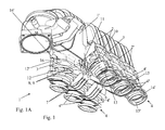
- FIGS. 1 to 5 appended drawings show a distributor 1 or intake manifold device 1, in particular for a V-cylinder engine.
- This distributor comprises two rows 2 'of at least two pipes 2, the outlet orifices 3 of the pipes 2 of each of the two rows 2' being situated in a respective plane P, P 'and these two planes forming between them an obtuse angle .
- Said distributor device 1 also comprises, for each row of pipes 2, an intermediate connecting plate 4, preferably with a body 4 'in the form of a perforated plate, these plates 4 being intended to be sandwiched with clamping between the ends 2 "of the pipes 2 and the mounting planes arranged in V of the cylinder heads, in order to make sealed fluidic connections between the pipes and the cylinders of the engine.
- the bodies 4 'of the two intermediate connection plates 4 are each connected to the body 1' of the distributor 1 via a connection 5 of retention and loose positioning, allowing limited relative displacement in translation and in pivoting of said plates 4 between them and / or relative to the body of the distributor 1 'and does not interfere with the final positioning of the latter during assembly with clamping body 1' of the distributor 1 on the cylinder heads with sandwiched said 4 'platinum body.
- the two plates 4 may be pre-assembled on the body 1 'of the distributor, while having a certain freedom of movement allowing their precise positioning between the pipes and the cylinder heads during assembly of the device 1 on the engine concerned.
- the displacement of the plates 4 makes it possible to modify the overall size of the distributor device 1, in terms of volume, shape and / or size reduction.
- articulated links with translational and pivotal faculty resulting from retention and positioning of the two platen bodies 4 'with each other and with respect to the body of the distributor 1' are at least partially combined and in particular have pivot axes coinciding.
- the common axis X of the limited pivoting of the plates 4 authorized by the connection 5 of retention and loose positioning extends between the two rows 2 'of tubings and parallel thereto, and that the limited translation allowed each platen 4 can be carried out at least in the direction of extension of the extremal portion of the tubes 2 of the row 2 'concerned by the plate 4 in question.
- connection 5 makes it possible to simplify the assembly of the plates 4 with the body of the distributor 1 'and to limit the interference with the external environment surrounding the distributor device 1.
- the two platinum bodies 4 ' are each provided with at least two lateral arms 6 provided at their free ends with at least one shaft portion or shaft portion 7 to be received each in a corresponding site 8 formed on the body 1 'of the distributor 1, this with limited translational and pivoting capability (e) s, the various shaft or axis portions 7, preferably formed integrally with the arms 6 and the platinum body 4 ', being mutually aligned.
- the two plates 4 are normally arranged in similar configurations relative to the body 1 'of the distributor, the shaft portions or axis 7 are perfectly aligned with each other and form a continuous pivot axis X in one piece.
- different displacements in translation in the free bearings 8 of said portions 7, resulting from differentiated displacement in translation of the platinum bodies 4 ', can lead to a duplication of said pivot axis in two substantially parallel axes, each associated with one turntables 4.
- each reception and retention site 8 consists of an open and partially free bearing allowing the introduction of a shaft or axis portion 7 by elastic deformation, radially by relative to the axis of said bearing.
- each open bearing 8 may, for example, consist of two opposed elastically deformable wings 9 formed on the body 1 'of the distributor 1 and having convergent, preferably curved free ends 9', defining between them a passage of width less than the diameter of the shaft or axis portions 7 and the different bearings 8 may be mutually aligned in a direction parallel to the longitudinal directions of the two rows 2 'of tubings 2 defining the common pivot axis X, and being located therebetween.
- each platinum body 4 ' is advantageously provided with at least two arms 6 or series of arms 6 mutually offset in the longitudinal direction of the respective platen body 4' and in that the two platens 4 are identical in constitution, said plates 4 being optionally secured to each other at the ends of their arms 6 by a rotary connection about the pivot axis X (not shown).
- each plate 4 may comprise two series of three arms 6, the adjacent arms being connected by axis or shaft portions 7, which are intended to engage in the bearings 8.
- abutment means 10 for example under the wing shape (s) or rib (s) formed (s) integrally on said portions 7 and / or said arms 6, determining by engagement cooperating with one or abutment means 11, formed (s) on the body 1 'of the distributor 1 or forming part of the sites 8, at least one extreme pivoting position, corresponding to a maximum permitted distance of the platinum body 4' considered, with respect to the ends 2 "of the tubes 2 of the row 2 concerned.
- abutment 11 may consist of a rib or continuous wing formed on the outside of the body 1 'of the distributor.
- the wings 10 forming a stop may also come into engagement with the walls of the sites 8 to possibly define opposite positions of extreme pivoting.
- each body 4' may comprise one or more lugs (12) for centering and positioning device, intended (s) to engage in a cavity (s) 12 'corresponding (s) present (s) in the distributor body 1', and located (s) around the outlet orifices 3 of the tubes 2, during the application of the plate 4 concerned on the ends 2 "of the tubes 2 of the row 2 'concerned, holes 13 for the passage of screws 16 for fixing and clamping the distributor 1 on the yokes being preferably also provided in the platinum body 4 '.
- the figures 1 and 5 in particular show that the perforated plates forming the platinum body 4 'are provided around each of their openings forming fluid passages, and on each of the two opposite faces of the platinum body 4', a groove 14, 14 'for receiving a corresponding seal 15, 15 '.
- the invention also relates to a motor vehicle with internal combustion engine, in particular with cylinders mounted in V, characterized in that it comprises a distributor device 1 as described above.
- the invention also has for one object a method of mounting an intake distributor on a V-cylinder engine, characterized in that it consists in providing an intake distributor device 1 as described above. , in the form of a preassembled module comprising the body of the distributor 1 'and the intermediate connection plates 4, to approach the distributor device 1 of the motor concerned so as to position it above the mounting planes of the cylinder heads, to come to bear the distribution device 1 on the yokes, the bodies of plates 4 'then automatically positioned between the ends 2 "of the tubes 2 and said V-shaped mounting planes said yokes by limited movements and guided in translation and in rotation of said platen body 4 'and, finally, to push and tighten the fastening screws 16, possibly placed in corresponding holes 16' of the body 1 'of the distribution admission 1 during the pre-assembly phase.
- the plates 4 are positioned, during the approach phase of the distributor device 1, under the action of gravity, in a position of extreme pivoting, resulting in at least a partial retraction of said plates 4 under the body of the distributor 1 ', such that they are located within the lateral space of said body 1', at least for the most part.
Landscapes
- Engineering & Computer Science (AREA)
- Chemical & Material Sciences (AREA)
- Combustion & Propulsion (AREA)
- Mechanical Engineering (AREA)
- General Engineering & Computer Science (AREA)
- Manufacturing & Machinery (AREA)
- Characterised By The Charging Evacuation (AREA)
Abstract
Description
La présente invention concerne le domaine des équipements des véhicules automobiles à moteurs à combustion interne, en particulier les équipements accessoires de tels moteurs, et a pour objets un dispositif de répartiteur d'admission et son procédé de montage sur un moteur.The present invention relates to the field of equipment of motor vehicles with internal combustion engines, in particular the accessory equipment of such engines, and has as its object an intake distributor device and its mounting method on an engine.
Les moteurs à combustion interne sont de manière connue équipés de répartiteurs ou collecteurs d'admission qui alimentent les cylindres en air de combustion, éventuellement mélangé à des gaz de combustion recyclés.Internal combustion engines are known in the known manner equipped with distributors or intake manifolds which feed the cylinders with combustion air, possibly mixed with recycled combustion gases.
Ces répartiteurs sont solidarisés rigidement et de manière étanche sur la ou les culasses du moteur au moyen de vis de fixation et avec interposition de platines de raccordement.These splitter boxes are rigidly and sealingly attached to the engine cylinder head (s) by means of fixing screws and with the interposition of connection plates.
Ces platines intègrent des moyens d'étanchéité et se présentent généralement sous la forme de plaques ajourées, assurant la liaison fluidique entre les sorties des tubulures et les entrées de la ou des culasse(s).These plates incorporate sealing means and are generally in the form of perforated plates, ensuring the fluid connection between the outlets of the tubes and the inputs of the cylinder head (s).
Actuellement, ces platines sont généralement mises en place sur le plan de montage de la culasse avant la fixation du répartiteur, ce qui entraîne une opération supplémentaire au niveau de la chaîne d'assemblage, requérant une grande précision d'exécution afin de garantir une bonne étanchéité. Cette opération est encore plus fastidieuse lorsque plusieurs platines distinctes doivent être mises en place.Currently, these plates are usually placed on the mounting plane of the cylinder head before fixing the distributor, which causes an additional operation at the assembly line, requiring a high accuracy of execution to ensure good seal. This operation is even more tedious when several separate plates must be put in place.
Il est également possible de mettre en place ces platines sur le répartiteur avant son montage sur le moteur.It is also possible to set up these plates on the splitter before mounting it on the engine.
Toutefois, un assemblage rigide de la ou des platines avec le répartiteur supprime toute possibilité de jeu au moment du serrage et peut ainsi résulter en un mésalignement au niveau de la culasse, en particulier en présence de plusieurs platines distinctes.However, a rigid assembly of the plate or plates with the distributor eliminates any possibility of play at the time of tightening and may result in a misalignment at the cylinder head, especially in the presence of several separate plates.
En outre, lorsque les platines sont fixées sur le répartiteur, l'encombrement de ce dernier, en particulier l'encombrement latéral du répartiteur, s'en trouve augmenté, empêchant, le cas échéant, un montage à travers un passage d'accès étroit, dans certaines configurations de construction, vers les culasses.In addition, when the plates are fixed on the distributor, the size of the latter, in particular the lateral size of the distributor, is increased, preventing, if necessary, mounting through a narrow access passage , in some construction configurations, to the cylinder heads.
La présente invention a notamment pour but de surmonter certaines, et préférentiellement tou(te)s, les limitations et/ou inconvénients exposés ci-dessus.The present invention is intended in particular to overcome some, and preferably all, the limitations and / or disadvantages described above.
A cet effet, la présente invention a pour objet un dispositif de répartiteur ou de collecteur d'admission, en particulier pour moteur à cylindres en V, comportant deux rangées d'au moins deux tubulures, les orifices de sortie des tubulures de chacune des deux rangées étant situés dans un plan respectif et ces deux plans formant entre eux un angle obtus, ledit dispositif de répartiteur comprenant également, pour chaque rangée de tubulures, une platine intermédiaire de raccordement, préférentiellement avec un corps sous la forme d'une plaque ajourée, ces platines étant destinées à être prises en sandwich avec serrage entre les extrémités des tubulures et les plans de montage arrangés en V des culasses pour réaliser des liaisons fluidiques étanches entre les tubulures et les cylindres du moteur,
dispositif de répartiteur caractérisé en ce que les corps des deux platines intermédiaires de raccordement sont reliés au corps du répartiteur par l'intermédiaire d'une liaison de rétention et de positionnement lâche, autorisant des déplacements relatifs limités en translation et en pivotement desdites platines entre elles et/ou par rapport au corps du répartiteur et n'entravant pas le positionnement final de ces dernières lors du montage avec serrage du corps du répartiteur sur les culasses avec prise en sandwich desdits corps de platine.For this purpose, the subject of the present invention is a distributor or intake manifold device, in particular for a V-cylinder engine, comprising two rows of at least two pipes, the outlet orifices of the pipes of each of the two rows being located in a respective plane and these two planes forming an obtuse angle between them, said distributor device also comprising, for each row of tubes, an intermediate connecting plate, preferably with a body in the form of a perforated plate, these plates being intended to be sandwiched with clamping between the ends of the pipes and the arranged mounting planes in V of the cylinder heads to make sealed fluidic connections between the pipes and the cylinders of the engine,
distributor device characterized in that the bodies of the two intermediate connection plates are connected to the body of the distributor by means of a loose retention and positioning connection, allowing limited relative displacement in translation and pivoting of said plates between them and / or relative to the body of the distributor and does not interfere with the final positioning of the latter during assembly with tightening of the body of the distributor on the cylinder heads with sandwiching said platinum bodies.
L'invention sera mieux comprise, grâce à la description ci-après, qui se rapporte à un mode de réalisation préféré, donné à titre d'exemple non limitatif, et expliqué avec référence aux dessins schématiques annexés, dans lesquels :
- les
figures 1A et1B sont des vues éclatées en perspective, selon deux directions différentes, d'un dispositif de répartiteur d'admission selon l'invention; - la
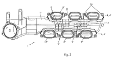
figure 2 est une vue de dessous du dispositif de répartiteur de lafigure 1 , après assemblage; - la
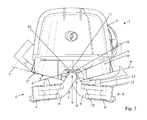
figure 3 est une vue en élévation frontale, dans la direction longitudinale du corps du répartiteur et dans la direction des rangées tubulaires, du répartiteur d'admission desfigures 1 et2 , les deux platines étant situées dans leurs positions de pivotement extrêmes, éloignées des rangées de tubulures qui leur sont respectivement associées; - la
figure 4 est une vue analogue à celle de lafigure 3 , les corps de platine ayant été pivotés et rapprochés des extrémités des tubulures (par mise en appui sur les plans de montage des culasses) ; - la
figure 5 et une vue en coupe selon un plan perpendiculaire à l'axe longitudinal du corps du répartiteur du dispositif représentéfigure 4 , et, - les
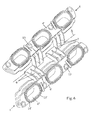
figures 6 et7 sont des vues en perspective, de dessus et de dessous, de l'ensemble de deux platines de raccordement faisant partie du dispositif de répartiteur représenté auxfigures 1 à 5 .
- the
Figures 1A and1B are exploded views in perspective, in two different directions, of an intake distributor device according to the invention; - the
figure 2 is a bottom view of the dispatcher device of thefigure 1 , after assembly; - the
figure 3 is a front elevational view, in the longitudinal direction of the tundish body and in the direction of the tubular rows, of the inlet manifold of thefigures 1 and2 , the two plates being located in their extreme pivoting positions, away from the rows of pipes which are respectively associated therewith; - the
figure 4 is a view similar to that of thefigure 3 , the platinum bodies having been pivoted and brought closer to the ends of the tubes (by bearing on the mounting planes of the cylinder heads); - the
figure 5 and a sectional view along a plane perpendicular to the longitudinal axis of the body of the distributor of the device shownfigure 4 and, - the
figures 6 and7 are perspective views, from above and below, of the set of two connection plates forming part of the distributor device shown in FIGS.Figures 1 to 5 .
Les
Ce répartiteur comporte deux rangées 2' d'au moins deux tubulures 2, les orifices de sortie 3 des tubulures 2 de chacune des deux rangées 2' étant situés dans un plan respectif P, P' et ces deux plans formant entre eux un angle obtus.This distributor comprises two rows 2 'of at least two
Ledit dispositif de répartiteur 1 comprend également, pour chaque rangée de tubulures 2, une platine intermédiaire de raccordement 4, préférentiellement avec un corps 4' sous la forme d'une plaque ajourée, ces platines 4 étant destinées à être prises en sandwich avec serrage entre les extrémités 2" des tubulures 2 et les plans de montage arrangés en V des culasses, ce afin de réaliser des liaisons fluidiques étanches entre les tubulures et les cylindres du moteur.Said
Conformément à l'invention, les corps 4' des deux platines intermédiaires de raccordement 4 sont chacun reliés au corps 1' du répartiteur 1 par l'intermédiaire d'une liaison 5 de rétention et de positionnement lâche, autorisant des déplacements relatifs limités en translation et en pivotement desdites platines 4 entre elles et/ou par rapport au corps du répartiteur 1' et n'entravant pas le positionnement final de ces dernières lors du montage avec serrage du corps 1' du répartiteur 1 sur les culasses avec prise en sandwich desdits corps de platine 4'.According to the invention, the bodies 4 'of the two
Ainsi, les deux platines 4 peuvent être prémontées sur le corps 1' du répartiteur, tout en disposant d'une certaine liberté de mouvement permettant leur positionnement précis entre les tubulures et les culasses lors du montage du dispositif 1 sur le moteur concerné.Thus, the two
En outre, le déplacement des platines 4 permet de modifier l'encombrement global du dispositif de répartiteur 1, en terme de volume, de forme et/ou de réduction de dimension.In addition, the displacement of the
De manière avantageuse, les liaisons articulées avec faculté de translation et de pivotement, résultant des liaisons 5 de rétention et de positionnement des deux corps de platine 4' entre eux et par rapport au corps du répartiteur 1', sont au moins partiellement confondues et présentent notamment des axes de pivotement confondus. De plus, l'axe commun X du pivotement limité des platines 4 autorisé par la liaison 5 de rétention et de positionnement lâche, s'étend entre les deux rangées 2' de tubulures et parallèlement à celles-ci, et que la translation limitée autorisée de chaque platine 4 peut s'effectuer au moins dans la direction d'extension de la portion extrémale des tubulures 2 de la rangée 2' concernée par la platine 4 considérée.Advantageously, articulated links with translational and pivotal faculty resulting from retention and positioning of the two platen bodies 4 'with each other and with respect to the body of the distributor 1', are at least partially combined and in particular have pivot axes coinciding. In addition, the common axis X of the limited pivoting of the
Une telle configuration localisée et escamotée des liaisons 5 permet de simplifier l'assemblage des platines 4 avec le corps du répartiteur 1' et de limiter les interférences avec l'environnement extérieur entourant le dispositif de répartiteur 1.Such a localized and retracted configuration of the
En accord avec un mode de construction possible de l'invention, ressortant des figures des dessins annexés, notamment des
Les deux platines 4 étant normalement disposées dans des configurations analogues par rapport au corps 1' du répartiteur, les portions d'arbre ou d'axe 7 sont parfaitement alignées entre elles et forment un axe de pivotement X continu d'un seul tenant. Toutefois, des déplacements en translation différents dans les paliers libres 8 desdites portions 7, résultant de déplacement en translation différenciés des corps de platine 4', peuvent aboutir à un dédoublement dudit axe de pivotement en deux axes sensiblement parallèles, associés chacun à l'une des platines 4.The two
Selon une variante de réalisation pratique préférée de l'invention, chaque site 8 de réception et de rétention consiste en un palier ouvert et partiellement libre autorisant l'introduction d'une portion d'arbre ou d'axe 7 par déformation élastique, radialement par rapport à l'axe dudit palier.According to a preferred practical variant embodiment of the invention, each reception and
Plus précisément, et comme le montrent les
Comme le montrent les
A titre d'exemple, chaque platine 4 peut comprendre deux séries de trois bras 6, les bras adjacents étant reliés par des portions d'axe ou d'arbre 7, lesquelles sont destinées à s'engager dans les paliers 8.By way of example, each
Afin de pouvoir garantir le positionnement des corps de platine 4' dans une configuration autorisant un montage avec mise en place automatique des platines 4 entre les tubulures 4 et les culasses du moteur, tout en n'entravant pas leur liberté de mouvement dans des plages prédéterminées, il est prévu qu'au moins certaines des portions d'arbre ou d'axe 7 et/ou au moins certains des bras latéraux 6 de chacune des platines 4 sont muni(e)s de moyens de butée 10, par exemple sous la forme d'aile(s) ou de nervure(s) formée(s) d'un seul tenant sur lesdites portions 7 et/ou lesdits bras 6, déterminant par engagement coopérant avec un ou des moyens de contrebutée 11, formé(s) sur le corps 1' du répartiteur 1 ou faisant partie des sites 8, au moins une position de pivotement extrême, correspondant à un éloignement maximal autorisé du corps de platine 4' considéré, par rapport aux extrémités 2" des tubulures 2 de la rangée 2' concernée.In order to be able to guarantee the positioning of the platen bodies 4 'in a configuration allowing an assembly with automatic positioning of the
Comme le montrent les
En vue de parvenir automatiquement à un positionnement précis des corps de platine 4' par rapport aux extrémités 2" des tubulures 2, lors de leur rapprochement mutuel par pivotement, chaque corps 4' peut comporter un ou plusieurs ergot(s) 12 de centrage et de positionnement, destiné(s) à s'engager dans une ou des cavité(s) 12' correspondante(s) présente(s) dans le corps de répartiteur 1', et située(s) autour des orifices de sortie 3 des tubulures 2, lors de l'application de la platine 4 concernée sur les extrémités 2" des tubulures 2 de la rangée 2' concernée, des orifices 13 de passage des vis 16 de fixation et de serrage du répartiteur 1 sur les culasses étant préférentiellement également prévus dans le corps de platine 4'.With a view to automatically achieving precise positioning of the platen bodies 4 'with respect to the
Les
L'invention concerne également un véhicule automobile à moteur à combustion interne, notamment avec des cylindres montés en V, caractérisé en ce qu'il comporte un dispositif de répartiteur 1 tel que décrit ci-dessus.The invention also relates to a motor vehicle with internal combustion engine, in particular with cylinders mounted in V, characterized in that it comprises a
Enfin, l'invention a aussi pour un objet un procédé de montage d'un répartiteur d'admission sur un moteur à cylindres en V, caractérisé en ce qu'il consiste à fournir un dispositif de répartiteur d'admission 1 tel que décrit précédemment, sous la forme d'un module prémonté comprenant le corps du répartiteur 1' et les platines intermédiaires de raccordement 4, à approcher le dispositif 1 de répartiteur du moteur concerné de manière à le positionner au-dessus des plans de montage des culasses, à venir mettre en appui le dispositif de répartiteur 1 sur les culasses, les corps de platines 4' se positionnant alors automatiquement entre les extrémités 2" des tubulures 2 et lesdits plans de montage en V desdites culasses par des déplacements limités et guidés en translation et en rotation desdits corps de platine 4' et, enfin, à enfoncer et à serrer les vis de fixation 16, éventuellement mises en place dans des orifices 16' correspondants du corps 1' du répartiteur d'admission 1 lors de la phase de prémontage.Finally, the invention also has for one object a method of mounting an intake distributor on a V-cylinder engine, characterized in that it consists in providing an
De manière avantageuse, et grâce aux dispositions de l'invention, les platines 4 sont positionnées, durant la phase d'approche du dispositif de répartiteur 1, sous l'action de la pesanteur, dans une position de pivotement extrême, résultant en un escamotage au moins partiel desdites platines 4 sous le corps du répartiteur 1', de telle manière qu'elles soient situées à l'intérieur de l'encombrement latéral dudit corps 1', au moins en majeure partie.Advantageously, and thanks to the provisions of the invention, the
Bien entendu, l'invention n'est pas limitée au mode de réalisation décrit et représenté aux dessins annexés. Des modifications restent possibles, notamment du point de vue de la constitution des divers éléments ou par substitution d'équivalents techniques, sans sortir pour autant du domaine de protection de l'invention.Of course, the invention is not limited to the embodiment described and shown in the accompanying drawings. Modifications are possible, particularly from the point of view of the constitution of the various elements or by substitution of technical equivalents, without departing from the scope of protection of the invention.
Claims (12)
dispositif de répartiteur (1) caractérisé en ce que les corps (4') des deux platines intermédiaires de raccordement (4) sont chacun reliés au corps (1') du répartiteur (1) par l'intermédiaire d'une liaison (5) de rétention et de positionnement lâche, autorisant des déplacements relatifs limités en translation et en pivotement desdites platines (4) entre elles et/ou par rapport au corps du répartiteur (1') et n'entravant pas le positionnement final de ces dernières lors du montage avec serrage du corps (1') du répartiteur (1) sur les culasses avec prise en sandwich desdits corps de platine (4').Dispatcher or intake manifold device, in particular for a V-cylinder engine, comprising two rows of at least two pipes, the outlet orifices of the pipes of each of the two rows being situated in a respective plane and these two planes forming between them an obtuse angle, said distributor device also comprising, for each row of tubes, an intermediate connecting plate, preferably with a body in the form of a perforated plate, these plates being intended to be sandwiched with clamping between the ends of the pipes and the arranged V-shaped mounting planes of the cylinder heads for making sealed fluidic connections between the pipes and the cylinders of the engine,
distributor device (1) characterized in that the bodies (4 ') of the two intermediate connection plates (4) are each connected to the body (1') of the distributor (1) via a link (5) retention and loosely positioning, allowing limited relative displacement in translation and pivoting of said plates (4) between them and / or relative to the body of the distributor (1 ') and does not interfere with the final positioning of the latter during the assembly with tightening of the body (1 ') of the distributor (1) on the cylinder heads with sandwiching said platinum body (4').
Applications Claiming Priority (1)
| Application Number | Priority Date | Filing Date | Title |
|---|---|---|---|
| FR1052387A FR2958338B1 (en) | 2010-03-31 | 2010-03-31 | INTAKE DISTRIBUTION DEVICE INCORPORATING PLATINUM AND METHOD OF MOUNTING IT TO A MOTOR |
Publications (2)
| Publication Number | Publication Date |
|---|---|
| EP2375048A1 true EP2375048A1 (en) | 2011-10-12 |
| EP2375048B1 EP2375048B1 (en) | 2014-08-27 |
Family
ID=43063889
Family Applications (1)
| Application Number | Title | Priority Date | Filing Date |
|---|---|---|---|
| EP20110305349 Active EP2375048B1 (en) | 2010-03-31 | 2011-03-29 | Air intake distributor device having plates and method of asssemblying on an engine |
Country Status (2)
| Country | Link |
|---|---|
| EP (1) | EP2375048B1 (en) |
| FR (1) | FR2958338B1 (en) |
Cited By (1)
| Publication number | Priority date | Publication date | Assignee | Title |
|---|---|---|---|---|
| US9556831B1 (en) | 2015-08-18 | 2017-01-31 | Frank Jasper Pty Ltd. | Thermal fuel delivery system with insertion assembly |
Citations (4)
| Publication number | Priority date | Publication date | Assignee | Title |
|---|---|---|---|---|
| US5544629A (en) * | 1994-06-29 | 1996-08-13 | Honda Giken Kogyo Kabushiki Kaisha | Intake system in v-shaped engine |
| US20020083924A1 (en) * | 2001-01-04 | 2002-07-04 | Siemens Automotive Inc. | Monocoque manifold assembly |
| US7302930B1 (en) * | 2006-12-13 | 2007-12-04 | Chrysler Llc | Air induction system and assembly method for an intake manifold with a single shaft and sensor for activating air control valves |
| US20090293831A1 (en) * | 2008-05-27 | 2009-12-03 | Toyota Jidosha Kabushiki Kaisha | Intake device of internal combustion engine and internal combustion engine |
-
2010
- 2010-03-31 FR FR1052387A patent/FR2958338B1/en active Active
-
2011
- 2011-03-29 EP EP20110305349 patent/EP2375048B1/en active Active
Patent Citations (4)
| Publication number | Priority date | Publication date | Assignee | Title |
|---|---|---|---|---|
| US5544629A (en) * | 1994-06-29 | 1996-08-13 | Honda Giken Kogyo Kabushiki Kaisha | Intake system in v-shaped engine |
| US20020083924A1 (en) * | 2001-01-04 | 2002-07-04 | Siemens Automotive Inc. | Monocoque manifold assembly |
| US7302930B1 (en) * | 2006-12-13 | 2007-12-04 | Chrysler Llc | Air induction system and assembly method for an intake manifold with a single shaft and sensor for activating air control valves |
| US20090293831A1 (en) * | 2008-05-27 | 2009-12-03 | Toyota Jidosha Kabushiki Kaisha | Intake device of internal combustion engine and internal combustion engine |
Cited By (3)
| Publication number | Priority date | Publication date | Assignee | Title |
|---|---|---|---|---|
| US9556831B1 (en) | 2015-08-18 | 2017-01-31 | Frank Jasper Pty Ltd. | Thermal fuel delivery system with insertion assembly |
| WO2017029607A1 (en) * | 2015-08-18 | 2017-02-23 | Frank Jasper Pty Ltd. | Thermal fuel delivery system with insertion assembly |
| US9797353B2 (en) | 2015-08-18 | 2017-10-24 | Frank Jasper Pty Ltd. | Thermal fuel delivery system with insertion assembly |
Also Published As
| Publication number | Publication date |
|---|---|
| FR2958338A1 (en) | 2011-10-07 |
| EP2375048B1 (en) | 2014-08-27 |
| FR2958338B1 (en) | 2012-03-23 |
Similar Documents
| Publication | Publication Date | Title |
|---|---|---|
| CA2539926C (en) | Pipe clamp | |
| EP2322779B1 (en) | Method for manufacturing an intake manifold and corresponding manifold | |
| FR2987401A1 (en) | METHOD FOR MAINTAINING AN ADAPTATION PART ON A TUBULAR HOUSING OF A TURBOMOTEUR, ADAPTATION PART AND CORRESPONDING HOLDING SYSTEM | |
| FR2979403A1 (en) | DEVICE FOR CONNECTING A STEERING COLUMN WITH A DIRECTION HOUSING. | |
| EP2375048B1 (en) | Air intake distributor device having plates and method of asssemblying on an engine | |
| FR2967113A1 (en) | Steering wheel support assembly for vehicle, has pivot providing rotary seal that ensures fluid connection of hydraulic lines, pivot and spindle at time of pivoting of spindle with respect to axle | |
| EP3144518A1 (en) | Arrangement for mounting an injector on a yoke by resilient fitting in a fixing flange | |
| FR2961868A1 (en) | DEVICE AND METHOD FOR ASSEMBLING TWO HULL ELEMENTS IN COMPOSITE MATERIAL | |
| WO2007042706A1 (en) | Device for supplying air to a multiple-cylinder engine head | |
| EP3683150B1 (en) | Device for pivoting connection between at least two parts, aircraft comprising a cowl equipped with said pivoting connection device | |
| EP0905405A1 (en) | Elastic joint, especially for an automotive wheel suspension | |
| EP3572331A1 (en) | Aircraft comprising at least one cover provided with an improved connection system | |
| FR2726075A1 (en) | HEAT EXCHANGER WITH TUBE BEAM AND METAL COLLECTOR | |
| FR2894643A1 (en) | Tubular end piece for connecting delivery pipe to inlet sleeve, has blocking arm comprising stop flange that rests against sleeve or stops rotation of end piece to assure locking of connection of end piece and another sleeve | |
| FR3070633A1 (en) | SHUT-OFF COMPONENT FOR AIR FLOW CONTROL DEVICE FOR FRONT-END MODULE FOR MOTOR VEHICLE | |
| EP3523164B1 (en) | Toothed wheel for a gear motor of a window wiper | |
| FR3136032A1 (en) | Device for connecting tubular pipes to a fluid circuit. | |
| FR2836701A1 (en) | Mounting device for Diesel engine fuel injection pipe comprises clamping element passed through by pipe and screwed to end fitting outside and intermediate collar immobilized between pipe and clamping element | |
| FR3055350A1 (en) | TURBOMACHINE WHEEL | |
| WO2007003829A2 (en) | Air intake splitter for an internal combustion engine | |
| FR2967112A1 (en) | Steering wheel support assembly for e.g. vehicle, has yoke fixed on spindle and movably mounted about pivot, where yoke includes ducts to allow fluid connection between ducts arranged in spindle and ducts arranged in pivot | |
| FR3134612A1 (en) | Connection device between two conduits comprising a ball joint and pipe connection comprising said connection device | |
| FR3039204A1 (en) | ASSEMBLY ASSEMBLY OF A TURBOMACHINE | |
| FR2986877A1 (en) | Control device for controlling flow of washing liquid in washing system for washing windscreen of car, has selection unit arranged for varying area of variable section of conduit to permit control of flow of washing liquid at end of body | |
| FR2973506A1 (en) | Electric sensor for use on rear axle of running gear to measure rotational speed of wheels of car, has electric cable passed through hole for being connected to body of case, and guide sleeve whose end positions are retained by clamping |
Legal Events
| Date | Code | Title | Description |
|---|---|---|---|
| PUAI | Public reference made under article 153(3) epc to a published international application that has entered the european phase |
Free format text: ORIGINAL CODE: 0009012 |
|
| AK | Designated contracting states |
Kind code of ref document: A1 Designated state(s): AL AT BE BG CH CY CZ DE DK EE ES FI FR GB GR HR HU IE IS IT LI LT LU LV MC MK MT NL NO PL PT RO RS SE SI SK SM TR |
|
| AX | Request for extension of the european patent |
Extension state: BA ME |
|
| 17P | Request for examination filed |
Effective date: 20120411 |
|
| RIC1 | Information provided on ipc code assigned before grant |
Ipc: F02M 35/10 20060101AFI20131024BHEP Ipc: F02M 35/116 20060101ALI20131024BHEP |
|
| GRAP | Despatch of communication of intention to grant a patent |
Free format text: ORIGINAL CODE: EPIDOSNIGR1 |
|
| INTG | Intention to grant announced |
Effective date: 20140321 |
|
| GRAS | Grant fee paid |
Free format text: ORIGINAL CODE: EPIDOSNIGR3 |
|
| GRAA | (expected) grant |
Free format text: ORIGINAL CODE: 0009210 |
|
| RAP1 | Party data changed (applicant data changed or rights of an application transferred) |
Owner name: SYSTEMES MOTEURS |
|
| AK | Designated contracting states |
Kind code of ref document: B1 Designated state(s): AL AT BE BG CH CY CZ DE DK EE ES FI FR GB GR HR HU IE IS IT LI LT LU LV MC MK MT NL NO PL PT RO RS SE SI SK SM TR |
|
| REG | Reference to a national code |
Ref country code: GB Ref legal event code: FG4D Free format text: NOT ENGLISH |
|
| REG | Reference to a national code |
Ref country code: CH Ref legal event code: EP |
|
| REG | Reference to a national code |
Ref country code: AT Ref legal event code: REF Ref document number: 684657 Country of ref document: AT Kind code of ref document: T Effective date: 20140915 |
|
| REG | Reference to a national code |
Ref country code: IE Ref legal event code: FG4D Free format text: LANGUAGE OF EP DOCUMENT: FRENCH |
|
| REG | Reference to a national code |
Ref country code: DE Ref legal event code: R096 Ref document number: 602011009429 Country of ref document: DE Effective date: 20141009 |
|
| REG | Reference to a national code |
Ref country code: DE Ref legal event code: R082 Ref document number: 602011009429 Country of ref document: DE Representative=s name: GEITZ TRUCKENMUELLER LUCHT CHRIST PATENTANWAEL, DE Ref country code: DE Ref legal event code: R082 Ref document number: 602011009429 Country of ref document: DE Representative=s name: BRP RENAUD UND PARTNER MBB, DE Ref country code: DE Ref legal event code: R082 Ref document number: 602011009429 Country of ref document: DE Representative=s name: GEITZ TRUCKENMUELLER LUCHT, PATENTANWAELTE, DE Ref country code: DE Ref legal event code: R082 Ref document number: 602011009429 Country of ref document: DE Representative=s name: BRP RENAUD UND PARTNER MBB RECHTSANWAELTE PATE, DE |
|
| REG | Reference to a national code |
Ref country code: AT Ref legal event code: MK05 Ref document number: 684657 Country of ref document: AT Kind code of ref document: T Effective date: 20140827 |
|
| REG | Reference to a national code |
Ref country code: LT Ref legal event code: MG4D |
|
| REG | Reference to a national code |
Ref country code: NL Ref legal event code: VDEP Effective date: 20140827 |
|
| PG25 | Lapsed in a contracting state [announced via postgrant information from national office to epo] |
Ref country code: BG Free format text: LAPSE BECAUSE OF FAILURE TO SUBMIT A TRANSLATION OF THE DESCRIPTION OR TO PAY THE FEE WITHIN THE PRESCRIBED TIME-LIMIT Effective date: 20141127 Ref country code: FI Free format text: LAPSE BECAUSE OF FAILURE TO SUBMIT A TRANSLATION OF THE DESCRIPTION OR TO PAY THE FEE WITHIN THE PRESCRIBED TIME-LIMIT Effective date: 20140827 Ref country code: PT Free format text: LAPSE BECAUSE OF FAILURE TO SUBMIT A TRANSLATION OF THE DESCRIPTION OR TO PAY THE FEE WITHIN THE PRESCRIBED TIME-LIMIT Effective date: 20141229 Ref country code: GR Free format text: LAPSE BECAUSE OF FAILURE TO SUBMIT A TRANSLATION OF THE DESCRIPTION OR TO PAY THE FEE WITHIN THE PRESCRIBED TIME-LIMIT Effective date: 20141128 Ref country code: NO Free format text: LAPSE BECAUSE OF FAILURE TO SUBMIT A TRANSLATION OF THE DESCRIPTION OR TO PAY THE FEE WITHIN THE PRESCRIBED TIME-LIMIT Effective date: 20141127 Ref country code: LT Free format text: LAPSE BECAUSE OF FAILURE TO SUBMIT A TRANSLATION OF THE DESCRIPTION OR TO PAY THE FEE WITHIN THE PRESCRIBED TIME-LIMIT Effective date: 20140827 Ref country code: ES Free format text: LAPSE BECAUSE OF FAILURE TO SUBMIT A TRANSLATION OF THE DESCRIPTION OR TO PAY THE FEE WITHIN THE PRESCRIBED TIME-LIMIT Effective date: 20140827 Ref country code: SE Free format text: LAPSE BECAUSE OF FAILURE TO SUBMIT A TRANSLATION OF THE DESCRIPTION OR TO PAY THE FEE WITHIN THE PRESCRIBED TIME-LIMIT Effective date: 20140827 |
|
| PG25 | Lapsed in a contracting state [announced via postgrant information from national office to epo] |
Ref country code: IS Free format text: LAPSE BECAUSE OF FAILURE TO SUBMIT A TRANSLATION OF THE DESCRIPTION OR TO PAY THE FEE WITHIN THE PRESCRIBED TIME-LIMIT Effective date: 20141227 Ref country code: LV Free format text: LAPSE BECAUSE OF FAILURE TO SUBMIT A TRANSLATION OF THE DESCRIPTION OR TO PAY THE FEE WITHIN THE PRESCRIBED TIME-LIMIT Effective date: 20140827 Ref country code: RS Free format text: LAPSE BECAUSE OF FAILURE TO SUBMIT A TRANSLATION OF THE DESCRIPTION OR TO PAY THE FEE WITHIN THE PRESCRIBED TIME-LIMIT Effective date: 20140827 Ref country code: AT Free format text: LAPSE BECAUSE OF FAILURE TO SUBMIT A TRANSLATION OF THE DESCRIPTION OR TO PAY THE FEE WITHIN THE PRESCRIBED TIME-LIMIT Effective date: 20140827 Ref country code: CY Free format text: LAPSE BECAUSE OF FAILURE TO SUBMIT A TRANSLATION OF THE DESCRIPTION OR TO PAY THE FEE WITHIN THE PRESCRIBED TIME-LIMIT Effective date: 20140827 Ref country code: HR Free format text: LAPSE BECAUSE OF FAILURE TO SUBMIT A TRANSLATION OF THE DESCRIPTION OR TO PAY THE FEE WITHIN THE PRESCRIBED TIME-LIMIT Effective date: 20140827 |
|
| PG25 | Lapsed in a contracting state [announced via postgrant information from national office to epo] |
Ref country code: NL Free format text: LAPSE BECAUSE OF FAILURE TO SUBMIT A TRANSLATION OF THE DESCRIPTION OR TO PAY THE FEE WITHIN THE PRESCRIBED TIME-LIMIT Effective date: 20140827 |
|
| PG25 | Lapsed in a contracting state [announced via postgrant information from national office to epo] |
Ref country code: EE Free format text: LAPSE BECAUSE OF FAILURE TO SUBMIT A TRANSLATION OF THE DESCRIPTION OR TO PAY THE FEE WITHIN THE PRESCRIBED TIME-LIMIT Effective date: 20140827 Ref country code: IT Free format text: LAPSE BECAUSE OF FAILURE TO SUBMIT A TRANSLATION OF THE DESCRIPTION OR TO PAY THE FEE WITHIN THE PRESCRIBED TIME-LIMIT Effective date: 20140827 Ref country code: DK Free format text: LAPSE BECAUSE OF FAILURE TO SUBMIT A TRANSLATION OF THE DESCRIPTION OR TO PAY THE FEE WITHIN THE PRESCRIBED TIME-LIMIT Effective date: 20140827 Ref country code: CZ Free format text: LAPSE BECAUSE OF FAILURE TO SUBMIT A TRANSLATION OF THE DESCRIPTION OR TO PAY THE FEE WITHIN THE PRESCRIBED TIME-LIMIT Effective date: 20140827 Ref country code: RO Free format text: LAPSE BECAUSE OF FAILURE TO SUBMIT A TRANSLATION OF THE DESCRIPTION OR TO PAY THE FEE WITHIN THE PRESCRIBED TIME-LIMIT Effective date: 20140827 Ref country code: SK Free format text: LAPSE BECAUSE OF FAILURE TO SUBMIT A TRANSLATION OF THE DESCRIPTION OR TO PAY THE FEE WITHIN THE PRESCRIBED TIME-LIMIT Effective date: 20140827 |
|
| REG | Reference to a national code |
Ref country code: DE Ref legal event code: R097 Ref document number: 602011009429 Country of ref document: DE |
|
| PG25 | Lapsed in a contracting state [announced via postgrant information from national office to epo] |
Ref country code: PL Free format text: LAPSE BECAUSE OF FAILURE TO SUBMIT A TRANSLATION OF THE DESCRIPTION OR TO PAY THE FEE WITHIN THE PRESCRIBED TIME-LIMIT Effective date: 20140827 |
|
| PLBE | No opposition filed within time limit |
Free format text: ORIGINAL CODE: 0009261 |
|
| STAA | Information on the status of an ep patent application or granted ep patent |
Free format text: STATUS: NO OPPOSITION FILED WITHIN TIME LIMIT |
|
| 26N | No opposition filed |
Effective date: 20150528 |
|
| REG | Reference to a national code |
Ref country code: DE Ref legal event code: R082 Ref document number: 602011009429 Country of ref document: DE Representative=s name: GEITZ TRUCKENMUELLER LUCHT CHRIST PATENTANWAEL, DE Ref country code: DE Ref legal event code: R082 Ref document number: 602011009429 Country of ref document: DE Representative=s name: GEITZ TRUCKENMUELLER LUCHT, PATENTANWAELTE, DE |
|
| PG25 | Lapsed in a contracting state [announced via postgrant information from national office to epo] |
Ref country code: LU Free format text: LAPSE BECAUSE OF FAILURE TO SUBMIT A TRANSLATION OF THE DESCRIPTION OR TO PAY THE FEE WITHIN THE PRESCRIBED TIME-LIMIT Effective date: 20150329 Ref country code: MC Free format text: LAPSE BECAUSE OF FAILURE TO SUBMIT A TRANSLATION OF THE DESCRIPTION OR TO PAY THE FEE WITHIN THE PRESCRIBED TIME-LIMIT Effective date: 20140827 |
|
| REG | Reference to a national code |
Ref country code: CH Ref legal event code: PL |
|
| GBPC | Gb: european patent ceased through non-payment of renewal fee |
Effective date: 20150329 |
|
| PG25 | Lapsed in a contracting state [announced via postgrant information from national office to epo] |
Ref country code: SI Free format text: LAPSE BECAUSE OF FAILURE TO SUBMIT A TRANSLATION OF THE DESCRIPTION OR TO PAY THE FEE WITHIN THE PRESCRIBED TIME-LIMIT Effective date: 20140827 |
|
| REG | Reference to a national code |
Ref country code: IE Ref legal event code: MM4A |
|
| PG25 | Lapsed in a contracting state [announced via postgrant information from national office to epo] |
Ref country code: IE Free format text: LAPSE BECAUSE OF NON-PAYMENT OF DUE FEES Effective date: 20150329 Ref country code: CH Free format text: LAPSE BECAUSE OF NON-PAYMENT OF DUE FEES Effective date: 20150331 Ref country code: LI Free format text: LAPSE BECAUSE OF NON-PAYMENT OF DUE FEES Effective date: 20150331 Ref country code: GB Free format text: LAPSE BECAUSE OF NON-PAYMENT OF DUE FEES Effective date: 20150329 |
|
| REG | Reference to a national code |
Ref country code: FR Ref legal event code: PLFP Year of fee payment: 6 |
|
| PG25 | Lapsed in a contracting state [announced via postgrant information from national office to epo] |
Ref country code: MT Free format text: LAPSE BECAUSE OF FAILURE TO SUBMIT A TRANSLATION OF THE DESCRIPTION OR TO PAY THE FEE WITHIN THE PRESCRIBED TIME-LIMIT Effective date: 20140827 |
|
| REG | Reference to a national code |
Ref country code: FR Ref legal event code: PLFP Year of fee payment: 7 |
|
| PG25 | Lapsed in a contracting state [announced via postgrant information from national office to epo] |
Ref country code: HU Free format text: LAPSE BECAUSE OF FAILURE TO SUBMIT A TRANSLATION OF THE DESCRIPTION OR TO PAY THE FEE WITHIN THE PRESCRIBED TIME-LIMIT; INVALID AB INITIO Effective date: 20110329 Ref country code: SM Free format text: LAPSE BECAUSE OF FAILURE TO SUBMIT A TRANSLATION OF THE DESCRIPTION OR TO PAY THE FEE WITHIN THE PRESCRIBED TIME-LIMIT Effective date: 20140827 |
|
| PG25 | Lapsed in a contracting state [announced via postgrant information from national office to epo] |
Ref country code: BE Free format text: LAPSE BECAUSE OF NON-PAYMENT OF DUE FEES Effective date: 20150331 |
|
| PG25 | Lapsed in a contracting state [announced via postgrant information from national office to epo] |
Ref country code: TR Free format text: LAPSE BECAUSE OF FAILURE TO SUBMIT A TRANSLATION OF THE DESCRIPTION OR TO PAY THE FEE WITHIN THE PRESCRIBED TIME-LIMIT Effective date: 20140827 |
|
| REG | Reference to a national code |
Ref country code: FR Ref legal event code: PLFP Year of fee payment: 8 |
|
| PG25 | Lapsed in a contracting state [announced via postgrant information from national office to epo] |
Ref country code: MK Free format text: LAPSE BECAUSE OF FAILURE TO SUBMIT A TRANSLATION OF THE DESCRIPTION OR TO PAY THE FEE WITHIN THE PRESCRIBED TIME-LIMIT Effective date: 20140827 |
|
| PG25 | Lapsed in a contracting state [announced via postgrant information from national office to epo] |
Ref country code: AL Free format text: LAPSE BECAUSE OF FAILURE TO SUBMIT A TRANSLATION OF THE DESCRIPTION OR TO PAY THE FEE WITHIN THE PRESCRIBED TIME-LIMIT Effective date: 20140827 |
|
| PGFP | Annual fee paid to national office [announced via postgrant information from national office to epo] |
Ref country code: FR Payment date: 20230222 Year of fee payment: 13 |
|
| PGFP | Annual fee paid to national office [announced via postgrant information from national office to epo] |
Ref country code: DE Payment date: 20230221 Year of fee payment: 13 |
|
| P01 | Opt-out of the competence of the unified patent court (upc) registered |
Effective date: 20230620 |