EP2375000B2 - Shaft seal - Google Patents
Shaft seal Download PDFInfo
- Publication number
- EP2375000B2 EP2375000B2 EP11159510.4A EP11159510A EP2375000B2 EP 2375000 B2 EP2375000 B2 EP 2375000B2 EP 11159510 A EP11159510 A EP 11159510A EP 2375000 B2 EP2375000 B2 EP 2375000B2
- Authority
- EP
- European Patent Office
- Prior art keywords
- shaft
- bearing housing
- oil
- seal
- bearing
- Prior art date
- Legal status (The legal status is an assumption and is not a legal conclusion. Google has not performed a legal analysis and makes no representation as to the accuracy of the status listed.)
- Active
Links
- 238000007789 sealing Methods 0.000 claims description 39
- 239000000463 material Substances 0.000 claims description 12
- 239000003921 oil Substances 0.000 description 88
- 239000007789 gas Substances 0.000 description 63
- 238000004939 coking Methods 0.000 description 10
- 239000007921 spray Substances 0.000 description 9
- 238000001816 cooling Methods 0.000 description 8
- 238000002485 combustion reaction Methods 0.000 description 6
- 230000000694 effects Effects 0.000 description 5
- 238000005461 lubrication Methods 0.000 description 3
- 238000004140 cleaning Methods 0.000 description 2
- 230000005484 gravity Effects 0.000 description 2
- 239000000314 lubricant Substances 0.000 description 2
- 239000010687 lubricating oil Substances 0.000 description 2
- 230000000149 penetrating effect Effects 0.000 description 2
- 238000006424 Flood reaction Methods 0.000 description 1
- 229910001060 Gray iron Inorganic materials 0.000 description 1
- 230000004888 barrier function Effects 0.000 description 1
- 150000001875 compounds Chemical class 0.000 description 1
- 239000000446 fuel Substances 0.000 description 1
- 230000017525 heat dissipation Effects 0.000 description 1
- 239000002184 metal Substances 0.000 description 1
- 229910052751 metal Inorganic materials 0.000 description 1
- 238000000034 method Methods 0.000 description 1
- 238000002156 mixing Methods 0.000 description 1
- 239000000203 mixture Substances 0.000 description 1
- 230000035515 penetration Effects 0.000 description 1
- 238000000926 separation method Methods 0.000 description 1
- 238000011144 upstream manufacturing Methods 0.000 description 1
- 238000013022 venting Methods 0.000 description 1
Images


Classifications
-
- F—MECHANICAL ENGINEERING; LIGHTING; HEATING; WEAPONS; BLASTING
- F02—COMBUSTION ENGINES; HOT-GAS OR COMBUSTION-PRODUCT ENGINE PLANTS
- F02B—INTERNAL-COMBUSTION PISTON ENGINES; COMBUSTION ENGINES IN GENERAL
- F02B39/00—Component parts, details, or accessories relating to, driven charging or scavenging pumps, not provided for in groups F02B33/00 - F02B37/00
-
- F—MECHANICAL ENGINEERING; LIGHTING; HEATING; WEAPONS; BLASTING
- F01—MACHINES OR ENGINES IN GENERAL; ENGINE PLANTS IN GENERAL; STEAM ENGINES
- F01D—NON-POSITIVE DISPLACEMENT MACHINES OR ENGINES, e.g. STEAM TURBINES
- F01D11/00—Preventing or minimising internal leakage of working-fluid, e.g. between stages
- F01D11/003—Preventing or minimising internal leakage of working-fluid, e.g. between stages by packing rings; Mechanical seals
-
- F—MECHANICAL ENGINEERING; LIGHTING; HEATING; WEAPONS; BLASTING
- F01—MACHINES OR ENGINES IN GENERAL; ENGINE PLANTS IN GENERAL; STEAM ENGINES
- F01D—NON-POSITIVE DISPLACEMENT MACHINES OR ENGINES, e.g. STEAM TURBINES
- F01D25/00—Component parts, details, or accessories, not provided for in, or of interest apart from, other groups
- F01D25/08—Cooling; Heating; Heat-insulation
- F01D25/12—Cooling
- F01D25/125—Cooling of bearings
-
- F—MECHANICAL ENGINEERING; LIGHTING; HEATING; WEAPONS; BLASTING
- F01—MACHINES OR ENGINES IN GENERAL; ENGINE PLANTS IN GENERAL; STEAM ENGINES
- F01D—NON-POSITIVE DISPLACEMENT MACHINES OR ENGINES, e.g. STEAM TURBINES
- F01D25/00—Component parts, details, or accessories, not provided for in, or of interest apart from, other groups
- F01D25/16—Arrangement of bearings; Supporting or mounting bearings in casings
-
- F—MECHANICAL ENGINEERING; LIGHTING; HEATING; WEAPONS; BLASTING
- F01—MACHINES OR ENGINES IN GENERAL; ENGINE PLANTS IN GENERAL; STEAM ENGINES
- F01D—NON-POSITIVE DISPLACEMENT MACHINES OR ENGINES, e.g. STEAM TURBINES
- F01D25/00—Component parts, details, or accessories, not provided for in, or of interest apart from, other groups
- F01D25/18—Lubricating arrangements
- F01D25/183—Sealing means
-
- F—MECHANICAL ENGINEERING; LIGHTING; HEATING; WEAPONS; BLASTING
- F02—COMBUSTION ENGINES; HOT-GAS OR COMBUSTION-PRODUCT ENGINE PLANTS
- F02B—INTERNAL-COMBUSTION PISTON ENGINES; COMBUSTION ENGINES IN GENERAL
- F02B39/00—Component parts, details, or accessories relating to, driven charging or scavenging pumps, not provided for in groups F02B33/00 - F02B37/00
- F02B39/14—Lubrication of pumps; Safety measures therefor
-
- F—MECHANICAL ENGINEERING; LIGHTING; HEATING; WEAPONS; BLASTING
- F05—INDEXING SCHEMES RELATING TO ENGINES OR PUMPS IN VARIOUS SUBCLASSES OF CLASSES F01-F04
- F05D—INDEXING SCHEME FOR ASPECTS RELATING TO NON-POSITIVE-DISPLACEMENT MACHINES OR ENGINES, GAS-TURBINES OR JET-PROPULSION PLANTS
- F05D2220/00—Application
- F05D2220/40—Application in turbochargers
-
- F—MECHANICAL ENGINEERING; LIGHTING; HEATING; WEAPONS; BLASTING
- F05—INDEXING SCHEMES RELATING TO ENGINES OR PUMPS IN VARIOUS SUBCLASSES OF CLASSES F01-F04
- F05D—INDEXING SCHEME FOR ASPECTS RELATING TO NON-POSITIVE-DISPLACEMENT MACHINES OR ENGINES, GAS-TURBINES OR JET-PROPULSION PLANTS
- F05D2240/00—Components
- F05D2240/55—Seals
- F05D2240/58—Piston ring seals
-
- F—MECHANICAL ENGINEERING; LIGHTING; HEATING; WEAPONS; BLASTING
- F05—INDEXING SCHEMES RELATING TO ENGINES OR PUMPS IN VARIOUS SUBCLASSES OF CLASSES F01-F04
- F05D—INDEXING SCHEME FOR ASPECTS RELATING TO NON-POSITIVE-DISPLACEMENT MACHINES OR ENGINES, GAS-TURBINES OR JET-PROPULSION PLANTS
- F05D2260/00—Function
- F05D2260/20—Heat transfer, e.g. cooling
- F05D2260/205—Cooling fluid recirculation, i.e. after cooling one or more components is the cooling fluid recovered and used elsewhere for other purposes
Definitions
- the invention relates to the field of turbomachines, in particular exhaust gas turbochargers subjected to exhaust gases from internal combustion engines.
- exhaust gas turbochargers are used as standard today, with a turbine in the exhaust gas tract of the internal combustion engine and with a compressor upstream of the internal combustion engine, which is connected to the turbine via a common shaft.
- an internal combustion engine is charged using an exhaust gas turbocharger, the filling quantity and thus the fuel mixture in the cylinders is increased, resulting in a noticeable increase in engine performance.
- the energy contained in the exhaust gas of a combustion engine can be converted into electrical or mechanical energy using a power turbine.
- a generator or a mechanical consumer is connected to the turbine shaft.
- a standard exhaust gas turbocharger consists of a rotor consisting of a shaft, a compressor wheel and a turbine wheel, a bearing for the shaft, flow-guiding housing parts (compressor housing or turbine housing) and the bearing housing.
- the shaft of the exhaust gas turbocharger must be sealed off from the cavity of the bearing housing with a suitable sealing concept.
- the internal pressure in the cavity of the bearing housing is usually equal to atmospheric pressure.
- the gas pressure in the flow channel on the compressor or turbine side depends on the current operating point of the exhaust gas turbocharger and is above the pressure in the cavity of the bearing housing at most operating points. In certain cases, however, a negative pressure is also to be expected, e.g. in partial load operation or at standstill.
- a turbine-side shaft seal of an exhaust gas turbocharger which consists of a simple oil collecting chamber on the turbine side of the radial bearing and a piston ring with a sealing effect between the shaft and the bearing housing.
- the bearing oil escaping axially from the radial bearing sprays onto the rotating shaft shoulder, which is offset outwards and is flung into the oil collection chamber by centrifugal forces.
- the bearing oil thrown off in this way then flows downwards within the oil collection chamber under the force of gravity and back into the oil circuit for bearing lubrication.
- Piston rings made of metal, for example gray cast iron, are used as standard to reduce gas leakage from the flow channel through the rear wheel space of the turbine into the cavity of the bearing housing.
- the piston ring which is under tension, is braced in a radial groove with an axial stop shoulder in the bearing housing.
- the rotating shaft is provided with a radial groove, with the piston ring being trapped axially within this groove and covering it radially. Due to the differential pressure between the exhaust gas pressure and the pressure inside the bearing housing, the piston ring is axially displaced in the direction of the existing pressure gradient within the groove until it stops.
- a positive pressure difference pressure in the flow channel is higher than in the cavity of the bearing housing means that the resulting gas leakage blows through the piston ring seal and the bearing oil that has accidentally penetrated the piston ring area is transported back into the oil collection chamber of the bearing housing.
- a first seal in the form of a gap, a labyrinth or a piston ring and a second seal in the form of a narrow gap or a labyrinth are provided on the rotor shaft, which between them enclose an oil drain channel which extends annularly around the circumference of the rotor shaft and which is drained by means of a housing-side oil drain groove and a shaft-side oil drain groove arranged in the same position as the axis.
- a ring-shaped sealing web which protrudes in the radial direction of the rotor shaft with one end freely into the ring-shaped oil drain channel and represents a barrier acting in the axial direction for lubricant penetrating the oil drain channel and radially covers the gap of the second seal.
- an exhaust gas turbocharger which consists of a two-part bearing housing, in which oil is sprayed onto the surface of the second part from a first part for cooling.
- the object of the present invention is to create a shaft seal for a turbomachine shaft mounted in a bearing housing, in which the drainage behavior of the lubricating oil can be improved and the risk of coking of the piston ring seal can be minimized by active cooling of the sealing part.
- the shaft seal according to the invention of a turbomachine shaft mounted in a bearing housing between a cavity in the bearing housing and a rear wheel space of an impeller of the turbomachine comprises a plurality of seals.
- a first, impeller-side seal which can be designed, for example, in the form of at least one piston ring
- a second, bearing-side seal which can be designed, for example, in the form of a sealing gap between the bearing housing and the shaft.
- An oil drainage chamber is arranged between the impeller-side seal and the bearing-side seal, which is delimited by a third, middle seal, which is designed, for example, in the form of a sealing gap between the bearing housing and the shaft.
- a gas outlet chamber is also arranged between the third seal and the first impeller-side seal.
- the third seal cleanly separates the two media, oil from the oil drain chamber, from the gas from the gas outlet chamber, which minimizes the risk of coking in the oil drain chamber, since the two media do not meet within the same collection chamber. Both media are discharged separately from each other through the third seal through at least two drainage channels laterally into the bearing housing plenum.
- the shaft seal according to the invention is also actively cooled by at least one obliquely aligned splash oil device, with no splash oil getting into the drain chambers.
- the shaft seal is designed in such a way that as much splashing oil as possible keeps the material temperatures of the bearing housing and the optional insert and the piston rings installed in it low and prevents the oil from coking in the various drain chambers.
- That area of the bearing housing which is part of the shaft seal designed according to the invention can be designed as an insert.
- the insert piece can be easily replaced in the event of operational wear or removed from the bearing housing for a short period of time, for example for cleaning purposes.
- a material with the highest possible thermal conductivity is to be selected as the material for this insert.
- that area of the shaft which is part of the shaft seal designed according to the invention and forms the oil drain chamber and the gas outlet chamber with its contour together with the bearing housing can be designed as a sleeve-shaped attachment rotating with the shaft.
- This attachment can be shrunk onto the shaft, screwed on or connected to the shaft in some other way in a positive and/or non-positive manner.
- the attachment is optionally made of a material that has improved thermal conductivity or an increased insulating effect compared to the material of the shaft. In this way, potential oil coking in the oil drain grooves can be prevented.
- FIG. 1 shows an exhaust gas turbocharger according to the prior art with a radial compressor 90 and a radial turbine 10.
- the housing of the exhaust gas turbocharger shown is shown partially cut away in order to be able to see the rotor with the compressor wheel 91, the shaft 20 and the turbine wheel 11.
- the air flow from the air inlet 92 via the compressor wheel 91 to the air outlet 93 and the gas flow from the gas inlet 12 via the turbine wheel 11 to the gas outlet 13 are indicated with bold arrows.
- the shaft 20 is rotatably mounted in the bearing housing 30, usually by means of two radial bearings and at least one axial bearing.
- the bearing housing includes an insert 31 (sealing sleeve) in the area of the shaft seal, which is implemented as a separate component.
- the insert piece 31 is ring-shaped and includes a radially outer oil drainage channel 52 for the splash oil thrown radially outwards from the radial bearing 34 and discharged laterally.
- the insert is sprayed directly or indirectly with spray oil and is thereby actively cooled.
- the spray oil is directed onto the components to be cooled by the oil spray device 61 .
- the oil spray is supplied through the oil duct 60 in the turbine-side bearing flange 62.
- the oil spray device 61 is designed and aligned as a bore in such a way that the oil spray hits the inner contour 63 in the area of the bearing housing 30 and the insert piece in the area of the oil drainage channel 52 wetted.
- the splash oil and the oil from the bearing 34 and oil drain channel 51 cool the insert and the piston rings, seals and drain chambers located therein extensively and coking is largely prevented.
- the insert piece 31 is optionally made from a material with the highest possible thermal conductivity. Furthermore, the components of the shaft seal 31, 30, 41, 42 can be separated from the hot turbine rear wall 11 and wheel rear space 15 by an additional heat plate 70.
- the heat plate 70 is arranged in the area of the wheel rear space 15 between the hot turbine rear wall 11 and the insert 31 of the shaft seal.
- the heat plate rests on the insert piece 31 with a bearing surface 71 in the radially inner area. This heat plate 70 additionally reduces the material temperatures in the area of the insert 31 and the piston rings 41, 42, which in turn minimizes the tendency to form coking.
- the oil drainage channel 52 is delimited in the axial direction by a radially extended sealing plate 32 which in turn is itself cooled by the oil in the drainage channel 51 .
- the insert also includes recesses for receiving two series-arranged piston rings 41 and 42, which are known per se and whose mode of operation is described above in the prior art.
- the insert further comprises an oil drainage chamber 53, a separate gas outlet chamber 55 for gas leakage from the two piston rings 41 and 42 and a sealing web 33 which separates the oil drainage chamber 53 and the gas outlet chamber 55 from one another.
- the oil drainage channel 51 between the radial bearing 34 and the sealing plate 32 forms the first main drainage channel for the bearing oil emerging from the radial bearing.
- the sealing plate 32 forms a first radial web 21 of the shaft 20 with a radially opposite first web Sealing gap 43, due to which penetration of the bearing oil from the oil drainage channel 51 into the oil drainage chamber 53 is minimized.
- the rotating shaft contour of the oil discharge chamber 53 is provided with a discharge groove that is offset radially inward, resulting in two splash edges to the left and right of this groove within the oil discharge chamber 53 .
- the oil thrown through the splash edges into the radially outer region of the oil drain chamber 53 formed by the groove in the insert piece 31 flows downwards within the oil drain chamber 53 along the contour of the insert piece 31 due to gravity. So that the bearing oil can be fed back from the oil drain chamber 53 into the oil circuit for bearing lubrication, the oil drain chamber 53 has at least one oil drain channel 54 in the lower region.
- the insert piece 31 of the shaft seal designed according to the invention is characterized by a gas outlet chamber 55 which is arranged next to the oil drain chamber 53 and is separated from the oil drain chamber 53 by a circumferential sealing web 33 .
- the annular gas outlet chamber 55 is used for collecting the hot gas flowing through the piston rings 41 and 42 .
- the sealing web 33 forms a second radial sealing gap 44 with a radially opposite second web 22 of the shaft 20.
- the sealing gap 44 cleanly separates the two media oil from the oil drain chamber 53 from the gas from the gas outlet chamber 55.
- the gas collected in the gas outlet chamber 55 is in turn transferred through at least one separate gas discharge channel 56 within the insert piece 31 and separately from the oil discharge channel 54 into the common volume of the cavity 50 in the bearing housing.
- the intentional separation of the two drains is intended to prevent the two media from mixing in the area of the oil drain chamber 53, thereby reducing the risk of coking in the sealing compound.
- the major part of the bearing oil escaping from the radial bearing 34 is discharged to the outside through the large oil drainage channel 51 and the first sealing point 43 and is kept away from the piston ring section via the oil drainage channel 52 .
- outlets of the at least one oil drainage channel 54 and of the gas drainage channel 56 are offset in the circumferential direction, as shown in FIG 3 and 4 is shown.
- 3 shows a view from below of the insert 31 without shaft and adjacent housing parts.
- the openings of the two oil drain channels 54 and of the gas drain channel 56, which lead out of the insert at the bottom, are offset axially and in particular in the circumferential direction.
- 4 shows the outflow channels and the radially inwardly protruding sealing plate 32 and in the area of the gas outflow channel 56 the radially inwardly protruding sealing web 33 in the section along IV-IV.
- the offset channel outlets result in greater strength of the insert.
- the seals 43 and 44 are designed as radial sealing gaps.
- these seals can be supplemented or replaced with piston ring seals or other sealing elements.
- the bearing housing can be designed without a separate insert piece in the area of the shaft seal designed according to the invention.
- the corresponding grooves, sealing plates and sealing webs are embedded directly in the bearing housing.
- the embodiment described in detail with a separate insert piece has the advantage that the insert piece can be made of a material with good thermal conductivity (e.g. Ck45) for the purpose of cooling the sealing part and is therefore independent of the bearing housing material used (e.g. GGG -40).
- an insert can be easily replaced in the event of operational wear or can be removed from the bearing housing for a short period of time, for example for cleaning purposes.
- the rotating shaft contour of the turbine in the area of the shaft seal designed according to the invention can be implemented by a sleeve-shaped attachment 81 .
- the attachment 81 is shrunk onto a seat 82 on the shaft and an edge formed on the shaft serves as an axial stop 83 for the attachment.
- the attachment and the shaft seat are to be designed in such a way that the heat dissipation is maximized via the oil cooling and the heat input via the shrink fit on the wave is minimized.
- the attachment is therefore to be made of a material with good thermal conductivity.
- the oil drain channels are also cooled, which in turn minimizes the risk of coking in the drain brackets 53 and 55.
- the attachment 81 can also be fixed to the shaft in a non-positive and/or positive manner in a different way, for example by means of a screw connection (thread) between the attachment and the shaft.
- the shaft seal comprises two piston rings 41 and 42.
- only one piston ring can be provided, or further piston rings can be provided in the area or at other points of the shaft seal.
- the embodiment shown and described in detail shows the shaft seal designed according to the invention on the turbine side of an exhaust gas turbocharger or a power turbine.
- the shaft seal designed according to the invention can also be used analogously on the compressor side of an exhaust gas turbocharger, or in any other turbomachine.
Description
Die Erfindung bezieht sich auf das Gebiet der Strömungsmaschinen, insbesondere der mit Abgasen von Brennkraftmaschinen beaufschlagten Abgasturboladern.The invention relates to the field of turbomachines, in particular exhaust gas turbochargers subjected to exhaust gases from internal combustion engines.
Sie betrifft eine Wellenabdichtung einer solchen Strömungsmaschine.It relates to a shaft seal of such a turbomachine.
Für die Leistungssteigerung einer Verbrennungskraftmaschine werden heutzutage standardmässig Abgasturbolader eingesetzt, mit einer Turbine im Abgastrakt der Verbrennungskraftmaschine und mit einem der Verbrennungskraftmaschine vorgelagerten Verdichter, welcher mit der Turbine über eine gemeinsame Welle verbunden ist. Mit der Aufladung eines Verbrennungsmotors mittels Abgasturbolader wird die Füllmenge und somit das Kraftstoffgemisch in den Zylindern erhöht und daraus ein merklicher Leistungsanstieg für den Motor gewonnen. Optional kann die im Abgas eines Verbrennungsmotors gebundene Energie mittels einer Nutzturbine in elektrische oder mechanische Energie gewandelt werden. Dabei ist anstelle eines Verdichters wie beim Abgasturbolader ein Generator oder ein mechanischer Verbraucher an der Turbinewelle angeschlossen.To increase the performance of an internal combustion engine, exhaust gas turbochargers are used as standard today, with a turbine in the exhaust gas tract of the internal combustion engine and with a compressor upstream of the internal combustion engine, which is connected to the turbine via a common shaft. When an internal combustion engine is charged using an exhaust gas turbocharger, the filling quantity and thus the fuel mixture in the cylinders is increased, resulting in a noticeable increase in engine performance. Optionally, the energy contained in the exhaust gas of a combustion engine can be converted into electrical or mechanical energy using a power turbine. In this case, instead of a compressor, as with the exhaust gas turbocharger, a generator or a mechanical consumer is connected to the turbine shaft.
Ein Abgasturbolader setzt sich standardmässig aus einem Rotor, bestehend aus einer Welle, einem Verdichterrad und einem Turbinenrad, aus einer Lagerung für die Welle, aus strömungsführenden Gehäuseteilen (Verdichtergehäuse resp. Turbinengehäuse) und aus dem Lagergehäuse zusammen.A standard exhaust gas turbocharger consists of a rotor consisting of a shaft, a compressor wheel and a turbine wheel, a bearing for the shaft, flow-guiding housing parts (compressor housing or turbine housing) and the bearing housing.
Aufgrund des hohen Prozessdruckes im turbinen- wie auch verdichterseitigen Strömungsbereich ist die Welle des Abgasturboladers gegenüber dem Hohlraum des Lagergehäuses mit einem passenden Dichtkonzept abzudichten. Der Innendruck im Hohlraum des Lagergehäuses entspricht üblicherweise dem atmosphärischen Druck. Der Gasdruck im Strömungskanal der Verdichter- respektive Turbinenseite hängt dagegen vom aktuellen Betriebspunkt des Abgasturboladers ab und liegt in den meisten Betriebspunkten über dem Druck im Hohlraum des Lagergehäuses. In gewissen Fällen ist aber auch mit einem Unterdruck zu rechnen, z.B. im Teillastbetrieb oder bei Stillstand.Due to the high process pressure in the flow area on the turbine and compressor side, the shaft of the exhaust gas turbocharger must be sealed off from the cavity of the bearing housing with a suitable sealing concept. The internal pressure in the cavity of the bearing housing is usually equal to atmospheric pressure. The gas pressure in the flow channel on the compressor or turbine side, on the other hand, depends on the current operating point of the exhaust gas turbocharger and is above the pressure in the cavity of the bearing housing at most operating points. In certain cases, however, a negative pressure is also to be expected, e.g. in partial load operation or at standstill.
Aus
Zur Reduktion der Gasleckage aus dem Strömungskanal durch den Radrückraum der Turbine in den Hohlraum des Lagergehäuses werden standardmässig Kolbenringe aus Metal, beispielsweise Grauguss, eingesetzt. Der unter Spannung stehende Kolbenring wird in einer radialen Nut mit axialer Anschlagschulter im Lagergehäuse verspannt. Als Gegenstück zum Kolbenring wird die rotierende Welle mit einer radialen Nut versehen, wobei der Kolbenring innerhalb dieser Nut axial gefangen ist und diese radial überdeckt. Aufgrund des Differenzdrucks zwischen dem Abgasdruck und dem Druck im Inneren des Lagergehäuses wird der Kolbenring in Richtung des vorhandenen Druckgradienten innerhalb der Nut axial auf Anschlag verschoben. Durch die axiale Auflage des Kolbenrings an einer der Nutinnenfläche schleift sich dieser ein und dichtet das Lagergehäuseplenum relativ zur Abgasströmung ab. Zur Verbesserung der Dichtwirkung können auch zwei oder mehr Kolbenringe eingesetzt werden, wie dies etwa in
Aus
Dem entgegenzuwirken versucht die in
Aus
Bei allen beschriebenen, turbinenseitigen Wellenabdichtkonzepten besteht unter gewissen Umständen die Gefahr, dass heisse Gase aus dem Radrückraum der Abgasturbine durch die Kolbenringabdichtung entweichen, und das im Kolbenringbereich sowie der Ölablaufnuten verbleibende Lageröl lokal verbrennt und dadurch eine starke Verkokung der Wellenabdichtung und damit verbundenem Verschleiss verursacht. Die Verkokungsgefahr nimmt mit steigender Abgastemperatur und erhöhter Gasleckage durch die Kolbenringe sowie schlechter Bauteilkühlung zu. So ist eine aktive Kühlung dieser Dichtungspartie entscheidend für die Betriebssicherheit der Wellenabdichtung.With all of the turbine-side shaft sealing concepts described, there is a risk under certain circumstances that hot gases from the rear wheel space of the exhaust gas turbine will escape through the piston ring seal, and the bearing oil remaining in the piston ring area and the oil drain grooves will burn locally, causing severe coking on the shaft seal and the associated wear. The risk of coking increases with increasing exhaust gas temperature and increased gas leakage through the piston rings as well as poor component cooling. Active cooling of this sealing section is decisive for the operational reliability of the shaft seal.
Aus
Aus
Aus
Der vorliegenden Erfindung liegt die Aufgabe zugrunde, eine Wellenabdichtung einer in einem Lagergehäuse gelagerten Welle einer Strömungsmaschine zu schaffen bei welcher das Ablaufverhalten des Schmieröls verbessert sowie die Verkokungsgefahr der Kolbenringabdichtung durch aktive Kühlung der Dichtungspartie minimiert werden kann.The object of the present invention is to create a shaft seal for a turbomachine shaft mounted in a bearing housing, in which the drainage behavior of the lubricating oil can be improved and the risk of coking of the piston ring seal can be minimized by active cooling of the sealing part.
Die erfindungsgemässe Wellenabdichtung einer in einem Lagergehäuse gelagerten Welle einer Strömungsmaschine zwischen einem Hohlraum im Lagergehäuse und einem Radrückraum eines Laufrades der Strömungsmaschine umfasst mehrere Dichtungen. Eine erste, laufradseitige Dichtung, welche beispielsweise in Form mindestens eines Kolbenrings ausgebildet sein kann, sowie eine zweite, lagerseitige Dichtung, welche beispielsweise in Form eines Dichtspaltes zwischen dem Lagergehäuse und der Welle ausgebildet sein kann. Zwischen der laufradseitigen Dichtung und der lagerseitigen Dichtung ist eine Ölablaufkammer angeordnet, welche von einer dritten, mittleren Dichtung, die beispielsweise in Form eines Dichtspaltes zwischen dem Lagergehäuse und der Welle ausgebildet ist, begrenzt ist. Zwischen der dritten Dichtung und der ersten, laufradseitigen Dichtung ist zudem erfindungsgemäss eine Gasaustrittskammer angeordnet. Die dritte Dichtung trennt erfindungsgemäss die beiden Medien Öl aus der Ölablaufkammer vom Gas aus der Gasaustrittskammer sauber ab wodurch die Verkokungsgefahr in der Ölablaufkammer minimiert werden kann, da die beiden Medien nicht innerhalb der gleichen Sammelkammer aufeinander treffen. Beide Medien werden durch die dritte Dichtung getrennt voneinander durch mindestens zwei Ablaufkanäle seitlich ins Lagergehäuseplenum abgeleitet. Die erfindungsgemässe Wellenabdichtung wird zudem durch mindestens eine schräg ausgerichtete Spritzölvorrichtung aktiv gekühlt, wobei kein Spritzöl in die Ablaufkammern gelangen soll. Die Wellenabdichtung ist konstruktiv so gestaltet, dass möglichst viel Spritzöl die Materialtemperaturen des Lagergehäuses sowie des optionalen Einsatzstücks und den darin eingebauten Kolbenringen gering hält und eine Verkokung des Öls in den diversen Ablaufkammern unterbindet.The shaft seal according to the invention of a turbomachine shaft mounted in a bearing housing between a cavity in the bearing housing and a rear wheel space of an impeller of the turbomachine comprises a plurality of seals. A first, impeller-side seal, which can be designed, for example, in the form of at least one piston ring, and a second, bearing-side seal, which can be designed, for example, in the form of a sealing gap between the bearing housing and the shaft. An oil drainage chamber is arranged between the impeller-side seal and the bearing-side seal, which is delimited by a third, middle seal, which is designed, for example, in the form of a sealing gap between the bearing housing and the shaft. According to the invention, a gas outlet chamber is also arranged between the third seal and the first impeller-side seal. According to the invention, the third seal cleanly separates the two media, oil from the oil drain chamber, from the gas from the gas outlet chamber, which minimizes the risk of coking in the oil drain chamber, since the two media do not meet within the same collection chamber. Both media are discharged separately from each other through the third seal through at least two drainage channels laterally into the bearing housing plenum. The shaft seal according to the invention is also actively cooled by at least one obliquely aligned splash oil device, with no splash oil getting into the drain chambers. The shaft seal is designed in such a way that as much splashing oil as possible keeps the material temperatures of the bearing housing and the optional insert and the piston rings installed in it low and prevents the oil from coking in the various drain chambers.
Optional kann derjenige Bereich des Lagergehäuses, welcher Teil der erfindungsgemäss ausgebildeten Wellenabdichtung ist, als ein Einsatzstück ausgebildet sein. Das Einsatzstück kann bei betriebsbedingter Abnutzung leicht ersetzt oder aber etwa zu Reinigungszwecken kurzzeitig aus dem Lagergehäuse ausgebaut werden. Zudem ist als Material für dieses Einsatzstück ein Werkstoff mit möglichst hoher Wärmeleiteigenschaft zu wählen.Optionally, that area of the bearing housing which is part of the shaft seal designed according to the invention can be designed as an insert. The insert piece can be easily replaced in the event of operational wear or removed from the bearing housing for a short period of time, for example for cleaning purposes. In addition, a material with the highest possible thermal conductivity is to be selected as the material for this insert.
Optional kann derjenige Bereich der Welle, welcher Teil der erfindungsgemäss ausgebildeten Wellenabdichtung ist und mit seiner Kontur zusammen mit dem Lagergehäuse die Ölablaufkammer sowie die Gasaustrittskammer bildet, als ein mit der Welle mitrotierender, hülsenförmiger Aufsatz ausgebildet sein. Dieser Aufsatz kann auf die Welle aufgeschrumpft, aufgeschraubt oder auf andere Weise form- und/ oder kraftschlüssig mit der Welle verbunden werden. Der Aufsatz ist optional aus einem Material gefertigt, welches gegenüber dem Material der Welle eine verbesserte Wärmeleitfähigkeit oder eine erhöhte isolierenden Wirkung aufweist. Auf diese Weise kann eine potentielle Ölverkokung in den Ölablaufrillen unterbunden werden kann.Optionally, that area of the shaft which is part of the shaft seal designed according to the invention and forms the oil drain chamber and the gas outlet chamber with its contour together with the bearing housing can be designed as a sleeve-shaped attachment rotating with the shaft. This attachment can be shrunk onto the shaft, screwed on or connected to the shaft in some other way in a positive and/or non-positive manner. The attachment is optionally made of a material that has improved thermal conductivity or an increased insulating effect compared to the material of the shaft. In this way, potential oil coking in the oil drain grooves can be prevented.
Nachfolgend wird die erfindungsgemässe Wellenabdichtung anhand von Zeichnungen detailliert erläutert. Dabei zeigt
- Fig. 1
- eine teilweise aufgeschnittene Ansicht eines Abgasturboladers gemäss dem Stand der Technik mit einem Radialverdichter und einer Radialturbine,
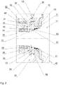
- Fig. 2
- einen entlang der Welle geführten Schnitt durch eine erfindungsgemäss ausgebildete, turbinenseitige Wellenabdichtung eines Abgasturboladers nach
Fig. 1 , - Fig. 3
- eine Ansicht von unten auf ein Gehäuseteil einer zweiten Ausführungsform der Wellenabdichtung nach
Fig. 2 , - Fig. 4
- einen entlang IV-IV geführten Schnitt durch das Gehäuseteil nach
Fig. 3 , und - Fig. 5
- die Wellenabdichtung gemäss
Fig. 2 mit einem auf der Welle aufgeschrumpften Aufsatz.
- 1
- a partially cutaway view of an exhaust gas turbocharger according to the prior art with a radial compressor and a radial turbine,
- 2
- 1 shows a section along the shaft through a turbine-side shaft seal of an exhaust gas turbocharger designed according to the
invention 1 , - 3
- a bottom view of a housing part of a second embodiment of the shaft seal
2 , - 4
- a section through the housing part along IV-IV
3 , and - figure 5
- the shaft seal according to
2 with an attachment shrunk onto the shaft.
Die Ölablaufrinne 51 zwischen dem Radiallager 34 und der Dichtplatte 32 bildet den ersten Hauptablaufkanal des aus dem Radiallager austretenden Lageröls. Die Dichtplatte 32 bildet mit einem radial gegenüberliegenden ersten Steg 21 der Welle 20 einen ersten radialen Dichtspalt 43, aufgrund dessen ein Eindringen des Lageröls aus der Ölablaufrinne 51 in die Ölablaufkammer 53 minimiert wird. Die rotierende Wellenkontur der Ölablaufkammer 53 ist mit einer radial nach Innen versetzten Ablaufnut versehen, wodurch sich innerhalb der Ölablaufkammer 53 zwei Abspritzkanten links und rechts dieser Nut ergeben. Das durch die Abspritzkanten in den durch die Nut im Einsatzstück 31 gebildeten, radial äusseren Bereich der Ölablaufkammer 53 geschleuderte Öl fliesst aufgrund der Schwerkraft innerhalb der Ölablaufkammer 53 entlang der Kontur des Einsatzstücks 31 nach unten. Damit das Lageröl aus der Ölablaufkammer 53 in den Ölkreislauf der Lagerschmierung zurückgeführt werden kann, weist die Ölablaufkammer 53 im unteren Bereich mindestens einen Ölablaufkanal 54 auf.The oil drainage channel 51 between the
Das Einsatzstück 31 der erfindungsgemäss ausgebildeten Wellenabdichtung zeichnet sich durch eine neben der Ölablaufkammer 53 angeordnete Gasaustrittskammer 55 aus, die von der Ölablaufkammer 53 durch einen umlaufenden Dichtsteg 33 abgetrennt ist. Die ringförmig ausgebildete Gasaustrittskammer 55 wird für das Sammeln des durch die Kolbenringe 41 und 42 durchströmenden heissen Gases verwendet. Der Dichtsteg 33 bildet mit einem radial gegenüberliegenden zweiten Steg 22 der Welle 20 einen zweiten radialen Dichtspalt 44. Der Dichtspalt 44 trennt erfindungsgemäss die beiden Medien Öl aus der Ölablaufkammer 53 vom Gas aus der Gasaustrittskammer 55 sauber ab. Das in der Gasaustrittskammer 55 aufgefangene Gas wird wiederum durch mindestens einen separaten Gasablaufkanal 56 innerhalb des Einsatzstücks 31 und getrennt vom Ölablaufkanal 54 ins gemeinsame Volumen des Hohlraums 50 im Lagergehäuse überführt. Durch die gezielte Trennung der beiden Abläufe soll eine Vermischung der beiden Medien im Bereich der Ölablaufkammer 53 unterbunden und dadurch die Verkokungsgefahr im Dichtverbund reduziert werden. Zudem wird durch die grosse Ölablaufrinne 51 sowie der ersten Dichtstelle 43 der Hauptanteil des aus dem Radiallager 34 austretenden Lageröls nach Aussen hin abgeführt und über die Ölablaufrinne 52 von der Kolbenringpartie ferngehalten.The
Optional sind die Austritte des mindestens einen Ölablaufkanals 54 und des Gasablaufkanals 56 in Umfangsrichtung versetzt angeordnet, wie dies in der
In der dargestellten Ausführungsform sind die Dichtungen 43 und 44 als radiale Dichtspalte ausgeführt. Optional können diese Dichtungen mit Kolbenringdichtung oder anderen Dichtelementen ergänzt oder ersetzt werden.In the illustrated embodiment, the
Optional kann das Lagergehäuse im Bereich der erfindungsgemäss ausgebildeten Wellenabdichtung ohne separates Einsatzstück ausgebildet sein. In diesem Fall sind die entsprechenden Nuten, Dichtplatten und Dichtstege direkt ins Lagergehäuse eingelassen. Gegenüber der einteilig ausgebildeten Variante ohne separates Einsatzstück weist die ausführlich beschriebene Ausführungsform mit separatem Einsatzstück den Vorteil auf, dass das Einsatzstück zwecks Kühlung der Dichtungspartie aus einem Material mit guter Wärmeleitfähigkeit (z.B. Ck45) gefertigt werden kann und somit unabhängig ist vom verwendeten Lagergehäusematerial (z.B. GGG-40). Weiter ist ein Einsatzstück bei betriebsbedingter Abnutzung leicht zu ersetzen oder aber etwa zu Reinigungszwecken kurzzeitig aus dem Lagergehäuse auszubauen.Optionally, the bearing housing can be designed without a separate insert piece in the area of the shaft seal designed according to the invention. In this case, the corresponding grooves, sealing plates and sealing webs are embedded directly in the bearing housing. Compared to the one-piece variant without a separate insert piece, the embodiment described in detail with a separate insert piece has the advantage that the insert piece can be made of a material with good thermal conductivity (e.g. Ck45) for the purpose of cooling the sealing part and is therefore independent of the bearing housing material used (e.g. GGG -40). Furthermore, an insert can be easily replaced in the event of operational wear or can be removed from the bearing housing for a short period of time, for example for cleaning purposes.
Optional kann gemäss
In der dargestellten Ausführungsform umfasst die Wellenabdichtung zwei Kolbenringe 41 und 42. Alternativ kann auch nur ein Kolbenring vorgesehen sein oder es können in dem Bereich oder an anderen Stellen der Wellenabdichtung weitere Kolbenringe vorgesehen sein.In the illustrated embodiment, the shaft seal comprises two
Die dargestellte und detailliert beschriebene Ausführungsform zeigt die erfindungsgemäss ausgebildete Wellenabdichtung auf der Turbinenseite eines Abgasturboladers oder einer Nutzturbine. Natürlich kann die erfindungsgemäss ausgebildete Wellenabdichtung auch analog auf der Verdichterseite eines Abgasturboladers, oder auch bei einer beliebigen anderen Strömungsmaschine eingesetzt werden.The embodiment shown and described in detail shows the shaft seal designed according to the invention on the turbine side of an exhaust gas turbocharger or a power turbine. Of course, the shaft seal designed according to the invention can also be used analogously on the compressor side of an exhaust gas turbocharger, or in any other turbomachine.
- 1010
- Turbineturbine
- 1111
- Turbinenradturbine wheel
- 1212
- Gaseinlassgas inlet
- 1313
- Gasaustrittgas leak
- 1515
- Radrückraum des Laufradesrear wheel space of the impeller
- 2020
- WelleWave
- 21, 2221, 22
- Dichtstegsealing bar
- 3030
- Lagergehäusebearing housing
- 3131
- Einsatzstück des LagergehäusesBearing housing insert
- 3232
- Dichtplattesealing plate
- 3333
- Dichtstegsealing bar
- 3434
- Radiallagerradial bearing
- 41, 4241, 42
- Kolbenringpiston ring
- 43, 4443, 44
- radialer Dichtspaltradial sealing gap
- 5050
- Hohlraum im Lagergehäusecavity in the bearing housing
- 51, 5251, 52
- Ölablaufrinneoil drain channel
- 5353
- Ölablaufkammeroil drain chamber
- 5454
- Ölablaufkanaloil drain channel
- 5555
- Gasaustrittskammergas exit chamber
- 5656
- Gasablaufkanalgas discharge channel
- 6060
- Ölkanaloil channel
- 6161
- Ölspritzvorrichtungoil spray device
- 6262
- Turbinenseitiger LagerflanschTurbine side bearing flange
- 6363
- Innenkontur des LagergehäusesInner contour of the bearing housing
- 7070
- Hitzeblechheat sheet
- 7171
- Auflagestellesupport point
- 8181
- Mit der Welle mitrotierender AufsatzAttachment rotating with the shaft
- 8282
- Wellensitzshaft fit
- 8383
- Axialanschlagaxial stop
- 9090
- Verdichtercompressor
- 9191
- Verdichterradcompressor wheel
- 9292
- Lufteinlassair intake
- 9393
- Luftaustrittair leakage
Claims (13)
- Shaft seal of a shaft (20), supported in a bearing housing (30), of a turbomachine between a cavity (50) in the bearing housing (30) and a wheel back space (15) of a rotating wheel (11) of the turbomachine, comprising a rotating wheel-side seal (41, 42) between the bearing housing (30, 31) and the shaft (20, 21) and also a bearing-side seal (43) between the bearing housing (30, 31) and the shaft (20, 21), wherein between the rotating wheel-side seal and the bearing-side seal provision is made for an oil outlet chamber (53), characterized in thatthe oil outlet chamber (53) is delimited by a third seal (44) between the bearing housing (30, 31) and the shaft (20, 22), and in that a gas discharge chamber (55) is arranged between the third seal and the rotating wheel-side seal, andan oil drain channel (52) is let into the bearing housing radially outside the oil outlet chamber (53), wherein at least one oil splashing device (61) is arranged in the region of the oil drain channel (52), with which oil splashing device the region of the oil drain channel can be splashed with oil, wherein the oil outlet chamber (53) and the gas discharge chamber (55) each comprise at least one separate outlet passage (54, 56).
- Shaft seal according to claim 1, wherein the rotating wheel-side seal is designed in the form of at least one piston ring (41, 42).
- Shaft seal according to claim 1 or 2, wherein the bearing-side seal is designed in the form of a sealing gap (43).
- Shaft seal according to any of claims 1 to 3, wherein the third seal is designed in the form of a sealing gap (44).
- Shaft seal according to claims 1 to 4, wherein inside the wheel back space (15), a heat shield (70) protects the shaft seal from the hot turbine back wall (11).
- Shaft seal according to any of claims 1 to 5, wherein the bearing housing, in the region of the shaft seal, comprises an insert piece (31), into which recesses are let in, forming the oil outlet chamber (53) and also the gas discharge chamber (55).
- Shaft seal according to any of claims 1 to 6, wherein the at least one outlet passage (54) of the oil outlet chamber (53) and the at least one outlet passage (56) of the gas discharge chamber (55) lead separately from each other into the cavity (50) in the bearing housing (30).
- Shaft seal according to claim 7, wherein the at least one outlet passage (54) of the oil outlet chamber (53) and the at least one outlet passage (56) of the gas discharge chamber (55) lead into the cavity (50) in the bearing housing (30) in an offset manner in the circumferential direction.
- Shaft seal according to any of claims 1 to 8, wherein the shaft, in the region of the shaft seal, comprises an attachment (81) which has a contour which together with the bearing housing forms the oil outlet chamber (53) and also the gas discharge chamber (55).
- Shaft seal according to claim 9, wherein the attachment (81) is produced from a material which compared with the material of the shaft has higher heat conductivity.
- Turbomachine, comprising at least one rotating wheel (11) arranged on a shaft (20), and also a bearing housing (30) in which the shaft (20) is rotatably supported, wherein a shaft seal according to any of claims 1 to 9 is arranged between the bearing housing (30) and the shaft (20).
- Exhaust gas turbocharger or power turbine, comprising at least one turbine rotating wheel (11) which is arranged on a shaft (20), and also a bearing housing (30) in which the shaft (20) is rotatably supported, wherein a shaft seal according to any of claims 1 to 9 is arranged between the bearing housing (30) and the shaft (20).
- Exhaust gas turbocharger, comprising at least one compressor rotating wheel (11) which is arranged on a shaft (20), and also a bearing housing (30) in which the shaft (20) is rotatably supported, wherein a shaft seal according to any of claims 1 to 9 is arranged between the bearing housing (30) and the shaft (20).
Applications Claiming Priority (1)
| Application Number | Priority Date | Filing Date | Title |
|---|---|---|---|
| DE102010003796A DE102010003796A1 (en) | 2010-04-09 | 2010-04-09 | shaft seal |
Publications (4)
| Publication Number | Publication Date |
|---|---|
| EP2375000A2 EP2375000A2 (en) | 2011-10-12 |
| EP2375000A3 EP2375000A3 (en) | 2017-06-28 |
| EP2375000B1 EP2375000B1 (en) | 2019-01-16 |
| EP2375000B2 true EP2375000B2 (en) | 2022-12-14 |
Family
ID=43824234
Family Applications (1)
| Application Number | Title | Priority Date | Filing Date |
|---|---|---|---|
| EP11159510.4A Active EP2375000B2 (en) | 2010-04-09 | 2011-03-24 | Shaft seal |
Country Status (6)
| Country | Link |
|---|---|
| US (1) | US9169738B2 (en) |
| EP (1) | EP2375000B2 (en) |
| JP (1) | JP5259768B2 (en) |
| KR (1) | KR101433817B1 (en) |
| CN (1) | CN102213117B (en) |
| DE (1) | DE102010003796A1 (en) |
Families Citing this family (19)
| Publication number | Priority date | Publication date | Assignee | Title |
|---|---|---|---|---|
| EP2218998B1 (en) * | 2009-02-03 | 2012-12-19 | Ipsen, Inc. | A sealing mechanism for a vacuum heat treating furnace |
| GB201220300D0 (en) | 2012-11-12 | 2012-12-26 | Cummins Ltd | Turbomachine bearing assembly preloading arrangement |
| EP2743460B1 (en) | 2012-12-14 | 2017-04-05 | ABB Turbo Systems AG | Shaft seal |
| CN103133064A (en) * | 2013-03-15 | 2013-06-05 | 联优机械(常熟)有限公司 | Self-sealing-function connecting shaft structure of expansion turbine external work output connection device |
| DE102013213023A1 (en) * | 2013-07-03 | 2015-01-08 | Continental Automotive Gmbh | Rotor for a turbocharger device, turbocharger device with a rotor and shaft for such a rotor |
| DE102014011849A1 (en) * | 2014-08-08 | 2016-02-11 | Man Diesel & Turbo Se | Shaft seal system and turbocharger |
| US9995161B2 (en) * | 2014-11-12 | 2018-06-12 | Borgwarner Inc. | Modular turbocharger clearance seal |
| US9732633B2 (en) * | 2015-03-09 | 2017-08-15 | Caterpillar Inc. | Turbocharger turbine assembly |
| JP2016188672A (en) * | 2015-03-30 | 2016-11-04 | 日野自動車株式会社 | Seal ring |
| US9638203B2 (en) * | 2015-09-15 | 2017-05-02 | Borgwarner Inc. | Bearing housing |
| DE102017202687A1 (en) | 2017-02-20 | 2018-08-23 | BMTS Technology GmbH & Co. KG | Bearing housing and a Abgasturoblader with such a housing |
| US10669873B2 (en) * | 2017-04-06 | 2020-06-02 | Raytheon Technologies Corporation | Insulated seal seat |
| WO2019077962A1 (en) * | 2017-10-16 | 2019-04-25 | 株式会社Ihi | Seal structure for supercharger |
| CN111226040B (en) * | 2017-10-30 | 2020-11-03 | 株式会社爱发科 | Vacuum pump |
| CN109026179A (en) * | 2018-08-02 | 2018-12-18 | 嘉兴博瑞涡轮增压技术有限公司 | A kind of novel supercharger sealing structure |
| CN108952848A (en) * | 2018-08-02 | 2018-12-07 | 嘉兴博瑞涡轮增压技术有限公司 | A kind of efficient turbocharger shell structure |
| US10746099B1 (en) * | 2019-04-03 | 2020-08-18 | GM Global Technology Operations LLC | Multi-step bore turbocharger |
| US11371521B2 (en) * | 2019-04-10 | 2022-06-28 | Borgwarner Inc. | High temperature face seal |
| US11655721B2 (en) | 2020-10-29 | 2023-05-23 | Borgwarner Inc. | Turbocharger including a sealing assembly |
Citations (4)
| Publication number | Priority date | Publication date | Assignee | Title |
|---|---|---|---|---|
| US4268229A (en) † | 1979-04-19 | 1981-05-19 | The Garrett Corporation | Turbocharger shaft seal arrangement |
| US4389052A (en) † | 1979-07-10 | 1983-06-21 | Ishikawajima-Harima Jukogyo Kabushiki Kaisha | Oil seal system for shaft of turbocharger |
| US5890881A (en) † | 1996-11-27 | 1999-04-06 | Alliedsignal Inc. | Pressure balanced turbocharger rotating seal |
| WO2010112864A2 (en) † | 2009-04-02 | 2010-10-07 | Cummins Turbo Technologies Limited | A rotating machine with shaft sealing arrangement |
Family Cites Families (26)
| Publication number | Priority date | Publication date | Assignee | Title |
|---|---|---|---|---|
| US2709567A (en) * | 1948-12-27 | 1955-05-31 | Garrett Corp | Turbine rotor bearing with cooling and lubricating means |
| GB1045973A (en) | 1962-07-14 | 1966-10-19 | Walter Eberspacher | Exhaust turbo supercharger |
| US3565497A (en) | 1969-05-23 | 1971-02-23 | Caterpillar Tractor Co | Turbocharger seal assembly |
| US3778194A (en) * | 1972-08-28 | 1973-12-11 | Carrier Corp | Turbocharger structure |
| DE2735034C2 (en) | 1976-08-19 | 1981-09-24 | Kabushiki Kaisha Komatsu Seisakusho, Tokyo | Exhaust gas turbocharger |
| US4196910A (en) | 1977-05-19 | 1980-04-08 | Ishikawajima-Harima Jukogyo Kabushiki Kaisha | Shaft sealing device for turbocharger |
| JPS5851027A (en) | 1981-09-16 | 1983-03-25 | Nitto Seiko Co Ltd | Removal device of fastener part |
| JPS5851027U (en) * | 1981-10-05 | 1983-04-06 | 株式会社日立製作所 | Cooling system for turbocharger |
| DE3219127C2 (en) * | 1982-05-21 | 1984-04-05 | Mtu Motoren- Und Turbinen-Union Friedrichshafen Gmbh, 7990 Friedrichshafen | Sealing device for turbo machines |
| US4477223A (en) * | 1982-06-11 | 1984-10-16 | Texas Turbine, Inc. | Sealing system for a turboexpander compressor |
| JPS6014246U (en) * | 1983-07-08 | 1985-01-30 | トヨタ自動車株式会社 | Turbo gear oil leak prevention device |
| JPS61202649A (en) | 1985-03-07 | 1986-09-08 | マルハ株式会社 | Apparatus for supplying and locating fish body |
| JPS61202649U (en) * | 1985-06-10 | 1986-12-19 | ||
| DE3737932A1 (en) | 1987-11-07 | 1989-05-18 | Mtu Friedrichshafen Gmbh | SEALING DEVICE BETWEEN SHAFT AND HOUSING OF A FLUID MACHINE |
| GB9222133D0 (en) * | 1992-10-21 | 1992-12-02 | Leavesley Malcolm G | Turbocharger apparatus |
| DE4330380A1 (en) * | 1993-09-08 | 1995-03-09 | Abb Management Ag | Exhaust turbocharger with multi-part bearing housing |
| JPH09264151A (en) * | 1996-03-29 | 1997-10-07 | Aisin Seiki Co Ltd | Oil leak preventing mechanism for turbo charger |
| WO2001027444A1 (en) * | 1999-10-12 | 2001-04-19 | Alm Development, Inc. | Bearing housing for a turbomachine |
| CN2517874Y (en) * | 2002-01-18 | 2002-10-23 | 陈浩 | Vehicle turbosupercharger |
| DE50208549D1 (en) * | 2002-09-02 | 2006-12-07 | Borgwarner Inc | Shaft seal for turbocharger |
| EP1860299A1 (en) | 2003-01-10 | 2007-11-28 | Honeywell International, Inc. | Sealing means for a lubrication system in a turbocharger |
| DE102004055429B3 (en) | 2004-11-17 | 2006-08-10 | Man B & W Diesel Ag | Sealing device for a particularly lubricated at standstill bearing a rotor shaft |
| EP1979579B1 (en) * | 2006-01-27 | 2013-04-10 | BorgWarner, Inc. | Vtg mechanism assembly using wave spring |
| US7544039B1 (en) * | 2006-06-14 | 2009-06-09 | Florida Turbine Technologies, Inc. | Dual spool shaft with intershaft seal |
| US8167534B2 (en) * | 2006-09-14 | 2012-05-01 | Solar Turbines Inc. | Seal for a turbine engine |
| CN201330623Y (en) * | 2008-12-15 | 2009-10-21 | 张焕元 | Bearing adjustable contact type sealing device of turbogenerator set |
-
2010
- 2010-04-09 DE DE102010003796A patent/DE102010003796A1/en active Pending
-
2011
- 2011-03-24 EP EP11159510.4A patent/EP2375000B2/en active Active
- 2011-04-01 KR KR1020110030379A patent/KR101433817B1/en active IP Right Grant
- 2011-04-07 US US13/081,897 patent/US9169738B2/en active Active
- 2011-04-08 CN CN201110093627.2A patent/CN102213117B/en active Active
- 2011-04-11 JP JP2011087016A patent/JP5259768B2/en active Active
Patent Citations (4)
| Publication number | Priority date | Publication date | Assignee | Title |
|---|---|---|---|---|
| US4268229A (en) † | 1979-04-19 | 1981-05-19 | The Garrett Corporation | Turbocharger shaft seal arrangement |
| US4389052A (en) † | 1979-07-10 | 1983-06-21 | Ishikawajima-Harima Jukogyo Kabushiki Kaisha | Oil seal system for shaft of turbocharger |
| US5890881A (en) † | 1996-11-27 | 1999-04-06 | Alliedsignal Inc. | Pressure balanced turbocharger rotating seal |
| WO2010112864A2 (en) † | 2009-04-02 | 2010-10-07 | Cummins Turbo Technologies Limited | A rotating machine with shaft sealing arrangement |
Also Published As
| Publication number | Publication date |
|---|---|
| KR20110113569A (en) | 2011-10-17 |
| CN102213117A (en) | 2011-10-12 |
| JP2011220338A (en) | 2011-11-04 |
| US9169738B2 (en) | 2015-10-27 |
| EP2375000B1 (en) | 2019-01-16 |
| EP2375000A2 (en) | 2011-10-12 |
| CN102213117B (en) | 2014-08-27 |
| DE102010003796A1 (en) | 2011-10-13 |
| US20110250067A1 (en) | 2011-10-13 |
| EP2375000A3 (en) | 2017-06-28 |
| KR101433817B1 (en) | 2014-08-27 |
| JP5259768B2 (en) | 2013-08-07 |
Similar Documents
| Publication | Publication Date | Title |
|---|---|---|
| EP2375000B2 (en) | Shaft seal | |
| EP2192272B1 (en) | Device for sealing a bearing box of a turbocharger | |
| DE69721036T2 (en) | PRESSURE BALANCED GASKET FOR TURBOCHARGER | |
| EP2071131B1 (en) | Seal for at least one shaft with at least one hydraulic seal | |
| DE102008044415A1 (en) | Methods and systems for sealing rotating machinery | |
| EP3392471A2 (en) | Bearing housing and an exhaust gas turbocharger with such a housing | |
| EP3267089A1 (en) | Oil distribution system and turbomaschine having an oil distribution system | |
| DE102016002719A1 (en) | Turbocharger and process | |
| EP2112332B1 (en) | Supporting ring for a guide vane assembly with an air-sealed channel | |
| WO2001016467A1 (en) | Turbine and method for discharging leakage fluid | |
| EP2743460B1 (en) | Shaft seal | |
| EP2730744B1 (en) | Exhaust gas turbo charger | |
| EP2054629B1 (en) | Shaft seal | |
| EP3374602B1 (en) | Arrangement for sealing a bearing casing and exhaust gas turbocharger comprising such arrangement | |
| EP0690204A2 (en) | Steamturbine with at least two seals in the casing for sealing the same | |
| CH703516B1 (en) | Turbomachinery. | |
| DE102019001167A1 (en) | Exhaust gas turbocharger | |
| CH703204B1 (en) | Turbomachinery. | |
| CH703515B1 (en) | Turbomachinery. | |
| EP2792855B1 (en) | Inner bearing block of an exhaust gas turbocharger | |
| EP3371420B1 (en) | Arrangement for separation of lubricant flows and exhaust gas turbocharger comprising such arrangement | |
| WO2008106931A1 (en) | Sealing element for sealing a gap between a stator and a rotor of an axial turbomachine | |
| WO2021110191A1 (en) | Seal carrier for a turbomachine, having slot-like openings in the seal body | |
| WO2013182306A1 (en) | Hydraulic sealing arrangement | |
| CH714385B1 (en) | Turbocharger. |
Legal Events
| Date | Code | Title | Description |
|---|---|---|---|
| PUAI | Public reference made under article 153(3) epc to a published international application that has entered the european phase |
Free format text: ORIGINAL CODE: 0009012 |
|
| AK | Designated contracting states |
Kind code of ref document: A2 Designated state(s): AL AT BE BG CH CY CZ DE DK EE ES FI FR GB GR HR HU IE IS IT LI LT LU LV MC MK MT NL NO PL PT RO RS SE SI SK SM TR |
|
| AX | Request for extension of the european patent |
Extension state: BA ME |
|
| PUAL | Search report despatched |
Free format text: ORIGINAL CODE: 0009013 |
|
| AK | Designated contracting states |
Kind code of ref document: A3 Designated state(s): AL AT BE BG CH CY CZ DE DK EE ES FI FR GB GR HR HU IE IS IT LI LT LU LV MC MK MT NL NO PL PT RO RS SE SI SK SM TR |
|
| AX | Request for extension of the european patent |
Extension state: BA ME |
|
| RIC1 | Information provided on ipc code assigned before grant |
Ipc: F01D 25/12 20060101ALI20170522BHEP Ipc: F01D 25/18 20060101ALI20170522BHEP Ipc: F01D 11/00 20060101AFI20170522BHEP |
|
| STAA | Information on the status of an ep patent application or granted ep patent |
Free format text: STATUS: REQUEST FOR EXAMINATION WAS MADE |
|
| 17P | Request for examination filed |
Effective date: 20171221 |
|
| RBV | Designated contracting states (corrected) |
Designated state(s): AL AT BE BG CH CY CZ DE DK EE ES FI FR GB GR HR HU IE IS IT LI LT LU LV MC MK MT NL NO PL PT RO RS SE SI SK SM TR |
|
| GRAP | Despatch of communication of intention to grant a patent |
Free format text: ORIGINAL CODE: EPIDOSNIGR1 |
|
| STAA | Information on the status of an ep patent application or granted ep patent |
Free format text: STATUS: GRANT OF PATENT IS INTENDED |
|
| INTG | Intention to grant announced |
Effective date: 20180627 |
|
| GRAS | Grant fee paid |
Free format text: ORIGINAL CODE: EPIDOSNIGR3 |
|
| GRAA | (expected) grant |
Free format text: ORIGINAL CODE: 0009210 |
|
| STAA | Information on the status of an ep patent application or granted ep patent |
Free format text: STATUS: THE PATENT HAS BEEN GRANTED |
|
| AK | Designated contracting states |
Kind code of ref document: B1 Designated state(s): AL AT BE BG CH CY CZ DE DK EE ES FI FR GB GR HR HU IE IS IT LI LT LU LV MC MK MT NL NO PL PT RO RS SE SI SK SM TR |
|
| REG | Reference to a national code |
Ref country code: GB Ref legal event code: FG4D Free format text: NOT ENGLISH |
|
| REG | Reference to a national code |
Ref country code: CH Ref legal event code: EP |
|
| REG | Reference to a national code |
Ref country code: IE Ref legal event code: FG4D Free format text: LANGUAGE OF EP DOCUMENT: GERMAN |
|
| REG | Reference to a national code |
Ref country code: DE Ref legal event code: R096 Ref document number: 502011015283 Country of ref document: DE |
|
| REG | Reference to a national code |
Ref country code: AT Ref legal event code: REF Ref document number: 1089844 Country of ref document: AT Kind code of ref document: T Effective date: 20190215 |
|
| REG | Reference to a national code |
Ref country code: NL Ref legal event code: MP Effective date: 20190116 |
|
| REG | Reference to a national code |
Ref country code: LT Ref legal event code: MG4D |
|
| PG25 | Lapsed in a contracting state [announced via postgrant information from national office to epo] |
Ref country code: NL Free format text: LAPSE BECAUSE OF FAILURE TO SUBMIT A TRANSLATION OF THE DESCRIPTION OR TO PAY THE FEE WITHIN THE PRESCRIBED TIME-LIMIT Effective date: 20190116 |
|
| PG25 | Lapsed in a contracting state [announced via postgrant information from national office to epo] |
Ref country code: ES Free format text: LAPSE BECAUSE OF FAILURE TO SUBMIT A TRANSLATION OF THE DESCRIPTION OR TO PAY THE FEE WITHIN THE PRESCRIBED TIME-LIMIT Effective date: 20190116 Ref country code: PT Free format text: LAPSE BECAUSE OF FAILURE TO SUBMIT A TRANSLATION OF THE DESCRIPTION OR TO PAY THE FEE WITHIN THE PRESCRIBED TIME-LIMIT Effective date: 20190516 Ref country code: LT Free format text: LAPSE BECAUSE OF FAILURE TO SUBMIT A TRANSLATION OF THE DESCRIPTION OR TO PAY THE FEE WITHIN THE PRESCRIBED TIME-LIMIT Effective date: 20190116 Ref country code: FI Free format text: LAPSE BECAUSE OF FAILURE TO SUBMIT A TRANSLATION OF THE DESCRIPTION OR TO PAY THE FEE WITHIN THE PRESCRIBED TIME-LIMIT Effective date: 20190116 Ref country code: NO Free format text: LAPSE BECAUSE OF FAILURE TO SUBMIT A TRANSLATION OF THE DESCRIPTION OR TO PAY THE FEE WITHIN THE PRESCRIBED TIME-LIMIT Effective date: 20190416 Ref country code: PL Free format text: LAPSE BECAUSE OF FAILURE TO SUBMIT A TRANSLATION OF THE DESCRIPTION OR TO PAY THE FEE WITHIN THE PRESCRIBED TIME-LIMIT Effective date: 20190116 Ref country code: SE Free format text: LAPSE BECAUSE OF FAILURE TO SUBMIT A TRANSLATION OF THE DESCRIPTION OR TO PAY THE FEE WITHIN THE PRESCRIBED TIME-LIMIT Effective date: 20190116 |
|
| PG25 | Lapsed in a contracting state [announced via postgrant information from national office to epo] |
Ref country code: BG Free format text: LAPSE BECAUSE OF FAILURE TO SUBMIT A TRANSLATION OF THE DESCRIPTION OR TO PAY THE FEE WITHIN THE PRESCRIBED TIME-LIMIT Effective date: 20190416 Ref country code: IS Free format text: LAPSE BECAUSE OF FAILURE TO SUBMIT A TRANSLATION OF THE DESCRIPTION OR TO PAY THE FEE WITHIN THE PRESCRIBED TIME-LIMIT Effective date: 20190516 Ref country code: GR Free format text: LAPSE BECAUSE OF FAILURE TO SUBMIT A TRANSLATION OF THE DESCRIPTION OR TO PAY THE FEE WITHIN THE PRESCRIBED TIME-LIMIT Effective date: 20190417 Ref country code: RS Free format text: LAPSE BECAUSE OF FAILURE TO SUBMIT A TRANSLATION OF THE DESCRIPTION OR TO PAY THE FEE WITHIN THE PRESCRIBED TIME-LIMIT Effective date: 20190116 Ref country code: LV Free format text: LAPSE BECAUSE OF FAILURE TO SUBMIT A TRANSLATION OF THE DESCRIPTION OR TO PAY THE FEE WITHIN THE PRESCRIBED TIME-LIMIT Effective date: 20190116 Ref country code: HR Free format text: LAPSE BECAUSE OF FAILURE TO SUBMIT A TRANSLATION OF THE DESCRIPTION OR TO PAY THE FEE WITHIN THE PRESCRIBED TIME-LIMIT Effective date: 20190116 |
|
| REG | Reference to a national code |
Ref country code: DE Ref legal event code: R026 Ref document number: 502011015283 Country of ref document: DE |
|
| PLBI | Opposition filed |
Free format text: ORIGINAL CODE: 0009260 |
|
| PLAX | Notice of opposition and request to file observation + time limit sent |
Free format text: ORIGINAL CODE: EPIDOSNOBS2 |
|
| PG25 | Lapsed in a contracting state [announced via postgrant information from national office to epo] |
Ref country code: SK Free format text: LAPSE BECAUSE OF FAILURE TO SUBMIT A TRANSLATION OF THE DESCRIPTION OR TO PAY THE FEE WITHIN THE PRESCRIBED TIME-LIMIT Effective date: 20190116 Ref country code: RO Free format text: LAPSE BECAUSE OF FAILURE TO SUBMIT A TRANSLATION OF THE DESCRIPTION OR TO PAY THE FEE WITHIN THE PRESCRIBED TIME-LIMIT Effective date: 20190116 Ref country code: AL Free format text: LAPSE BECAUSE OF FAILURE TO SUBMIT A TRANSLATION OF THE DESCRIPTION OR TO PAY THE FEE WITHIN THE PRESCRIBED TIME-LIMIT Effective date: 20190116 Ref country code: MC Free format text: LAPSE BECAUSE OF FAILURE TO SUBMIT A TRANSLATION OF THE DESCRIPTION OR TO PAY THE FEE WITHIN THE PRESCRIBED TIME-LIMIT Effective date: 20190116 Ref country code: DK Free format text: LAPSE BECAUSE OF FAILURE TO SUBMIT A TRANSLATION OF THE DESCRIPTION OR TO PAY THE FEE WITHIN THE PRESCRIBED TIME-LIMIT Effective date: 20190116 Ref country code: EE Free format text: LAPSE BECAUSE OF FAILURE TO SUBMIT A TRANSLATION OF THE DESCRIPTION OR TO PAY THE FEE WITHIN THE PRESCRIBED TIME-LIMIT Effective date: 20190116 Ref country code: IT Free format text: LAPSE BECAUSE OF FAILURE TO SUBMIT A TRANSLATION OF THE DESCRIPTION OR TO PAY THE FEE WITHIN THE PRESCRIBED TIME-LIMIT Effective date: 20190116 |
|
| REG | Reference to a national code |
Ref country code: CH Ref legal event code: PL |
|
| 26 | Opposition filed |
Opponent name: MAN ENERGY SOLUTIONS SE Effective date: 20191014 |
|
| PG25 | Lapsed in a contracting state [announced via postgrant information from national office to epo] |
Ref country code: LU Free format text: LAPSE BECAUSE OF NON-PAYMENT OF DUE FEES Effective date: 20190324 Ref country code: SM Free format text: LAPSE BECAUSE OF FAILURE TO SUBMIT A TRANSLATION OF THE DESCRIPTION OR TO PAY THE FEE WITHIN THE PRESCRIBED TIME-LIMIT Effective date: 20190116 |
|
| REG | Reference to a national code |
Ref country code: BE Ref legal event code: MM Effective date: 20190331 |
|
| PG25 | Lapsed in a contracting state [announced via postgrant information from national office to epo] |
Ref country code: CH Free format text: LAPSE BECAUSE OF NON-PAYMENT OF DUE FEES Effective date: 20190331 Ref country code: LI Free format text: LAPSE BECAUSE OF NON-PAYMENT OF DUE FEES Effective date: 20190331 Ref country code: IE Free format text: LAPSE BECAUSE OF NON-PAYMENT OF DUE FEES Effective date: 20190324 |
|
| PG25 | Lapsed in a contracting state [announced via postgrant information from national office to epo] |
Ref country code: SI Free format text: LAPSE BECAUSE OF FAILURE TO SUBMIT A TRANSLATION OF THE DESCRIPTION OR TO PAY THE FEE WITHIN THE PRESCRIBED TIME-LIMIT Effective date: 20190116 Ref country code: FR Free format text: LAPSE BECAUSE OF NON-PAYMENT OF DUE FEES Effective date: 20190331 Ref country code: BE Free format text: LAPSE BECAUSE OF NON-PAYMENT OF DUE FEES Effective date: 20190331 |
|
| PLBB | Reply of patent proprietor to notice(s) of opposition received |
Free format text: ORIGINAL CODE: EPIDOSNOBS3 |
|
| PG25 | Lapsed in a contracting state [announced via postgrant information from national office to epo] |
Ref country code: TR Free format text: LAPSE BECAUSE OF FAILURE TO SUBMIT A TRANSLATION OF THE DESCRIPTION OR TO PAY THE FEE WITHIN THE PRESCRIBED TIME-LIMIT Effective date: 20190116 |
|
| PG25 | Lapsed in a contracting state [announced via postgrant information from national office to epo] |
Ref country code: MT Free format text: LAPSE BECAUSE OF FAILURE TO SUBMIT A TRANSLATION OF THE DESCRIPTION OR TO PAY THE FEE WITHIN THE PRESCRIBED TIME-LIMIT Effective date: 20190116 |
|
| RAP2 | Party data changed (patent owner data changed or rights of a patent transferred) |
Owner name: ABB SCHWEIZ AG |
|
| REG | Reference to a national code |
Ref country code: DE Ref legal event code: R081 Ref document number: 502011015283 Country of ref document: DE Owner name: TURBO SYSTEMS SWITZERLAND LTD., CH Free format text: FORMER OWNER: ABB TURBO SYSTEMS AG, BADEN, CH Ref country code: DE Ref legal event code: R082 Ref document number: 502011015283 Country of ref document: DE Representative=s name: ZIMMERMANN & PARTNER PATENTANWAELTE MBB, DE Ref country code: DE Ref legal event code: R081 Ref document number: 502011015283 Country of ref document: DE Owner name: ABB SCHWEIZ AG, CH Free format text: FORMER OWNER: ABB TURBO SYSTEMS AG, BADEN, CH |
|
| RAP2 | Party data changed (patent owner data changed or rights of a patent transferred) |
Owner name: ABB SCHWEIZ AG |
|
| REG | Reference to a national code |
Ref country code: GB Ref legal event code: 732E Free format text: REGISTERED BETWEEN 20210225 AND 20210303 |
|
| REG | Reference to a national code |
Ref country code: GB Ref legal event code: 732E Free format text: REGISTERED BETWEEN 20210304 AND 20210310 |
|
| REG | Reference to a national code |
Ref country code: AT Ref legal event code: PC Ref document number: 1089844 Country of ref document: AT Kind code of ref document: T Owner name: ABB SCHWEIZ AG, CH Effective date: 20210217 |
|
| PG25 | Lapsed in a contracting state [announced via postgrant information from national office to epo] |
Ref country code: CY Free format text: LAPSE BECAUSE OF FAILURE TO SUBMIT A TRANSLATION OF THE DESCRIPTION OR TO PAY THE FEE WITHIN THE PRESCRIBED TIME-LIMIT Effective date: 20190116 |
|
| PG25 | Lapsed in a contracting state [announced via postgrant information from national office to epo] |
Ref country code: HU Free format text: LAPSE BECAUSE OF FAILURE TO SUBMIT A TRANSLATION OF THE DESCRIPTION OR TO PAY THE FEE WITHIN THE PRESCRIBED TIME-LIMIT; INVALID AB INITIO Effective date: 20110324 |
|
| RAP2 | Party data changed (patent owner data changed or rights of a patent transferred) |
Owner name: TURBO SYSTEMS SWITZERLAND LTD. |
|
| PG25 | Lapsed in a contracting state [announced via postgrant information from national office to epo] |
Ref country code: MK Free format text: LAPSE BECAUSE OF FAILURE TO SUBMIT A TRANSLATION OF THE DESCRIPTION OR TO PAY THE FEE WITHIN THE PRESCRIBED TIME-LIMIT Effective date: 20190116 |
|
| REG | Reference to a national code |
Ref country code: GB Ref legal event code: 732E Free format text: REGISTERED BETWEEN 20220922 AND 20220928 |
|
| REG | Reference to a national code |
Ref country code: DE Ref legal event code: R081 Ref document number: 502011015283 Country of ref document: DE Owner name: TURBO SYSTEMS SWITZERLAND LTD., CH Free format text: FORMER OWNER: ABB SCHWEIZ AG, BADEN, CH |
|
| PUAH | Patent maintained in amended form |
Free format text: ORIGINAL CODE: 0009272 |
|
| STAA | Information on the status of an ep patent application or granted ep patent |
Free format text: STATUS: PATENT MAINTAINED AS AMENDED |
|
| 27A | Patent maintained in amended form |
Effective date: 20221214 |
|
| AK | Designated contracting states |
Kind code of ref document: B2 Designated state(s): AL AT BE BG CH CY CZ DE DK EE ES FI FR GB GR HR HU IE IS IT LI LT LU LV MC MK MT NL NO PL PT RO RS SE SI SK SM TR |
|
| REG | Reference to a national code |
Ref country code: DE Ref legal event code: R102 Ref document number: 502011015283 Country of ref document: DE |
|
| PGFP | Annual fee paid to national office [announced via postgrant information from national office to epo] |
Ref country code: CZ Payment date: 20230320 Year of fee payment: 13 Ref country code: AT Payment date: 20230322 Year of fee payment: 13 |
|
| REG | Reference to a national code |
Ref country code: AT Ref legal event code: PC Ref document number: 1089844 Country of ref document: AT Kind code of ref document: T Owner name: TURBO SYSTEMS SWITZERLAND LTD, CH Effective date: 20230320 |
|
| PGFP | Annual fee paid to national office [announced via postgrant information from national office to epo] |
Ref country code: GB Payment date: 20230321 Year of fee payment: 13 Ref country code: DE Payment date: 20230321 Year of fee payment: 13 |