EP3374602B1 - Arrangement for sealing a bearing casing and exhaust gas turbocharger comprising such arrangement - Google Patents
Arrangement for sealing a bearing casing and exhaust gas turbocharger comprising such arrangement Download PDFInfo
- Publication number
- EP3374602B1 EP3374602B1 EP16790406.9A EP16790406A EP3374602B1 EP 3374602 B1 EP3374602 B1 EP 3374602B1 EP 16790406 A EP16790406 A EP 16790406A EP 3374602 B1 EP3374602 B1 EP 3374602B1
- Authority
- EP
- European Patent Office
- Prior art keywords
- cover
- rotor
- oil
- axially extending
- intermediate wall
- Prior art date
- Legal status (The legal status is an assumption and is not a legal conclusion. Google has not performed a legal analysis and makes no representation as to the accuracy of the status listed.)
- Active
Links
- 238000007789 sealing Methods 0.000 title claims description 97
- 239000003921 oil Substances 0.000 claims description 89
- 239000010687 lubricating oil Substances 0.000 claims description 40
- 238000007599 discharging Methods 0.000 claims 1
- 238000000926 separation method Methods 0.000 description 18
- 230000005484 gravity Effects 0.000 description 15
- 239000007789 gas Substances 0.000 description 14
- 238000002485 combustion reaction Methods 0.000 description 4
- 238000001816 cooling Methods 0.000 description 4
- 238000000034 method Methods 0.000 description 3
- 230000007423 decrease Effects 0.000 description 2
- 230000000694 effects Effects 0.000 description 2
- 238000005192 partition Methods 0.000 description 2
- 210000003323 beak Anatomy 0.000 description 1
- 230000000903 blocking effect Effects 0.000 description 1
- 239000000567 combustion gas Substances 0.000 description 1
- 230000006835 compression Effects 0.000 description 1
- 238000007906 compression Methods 0.000 description 1
- 230000001419 dependent effect Effects 0.000 description 1
- 230000002349 favourable effect Effects 0.000 description 1
- 239000000446 fuel Substances 0.000 description 1
- 230000003993 interaction Effects 0.000 description 1
- 239000000314 lubricant Substances 0.000 description 1
- 230000001050 lubricating effect Effects 0.000 description 1
- 239000000203 mixture Substances 0.000 description 1
- 230000035515 penetration Effects 0.000 description 1
- 239000007921 spray Substances 0.000 description 1
- 238000009736 wetting Methods 0.000 description 1
Images

Classifications
-
- F—MECHANICAL ENGINEERING; LIGHTING; HEATING; WEAPONS; BLASTING
- F01—MACHINES OR ENGINES IN GENERAL; ENGINE PLANTS IN GENERAL; STEAM ENGINES
- F01D—NON-POSITIVE DISPLACEMENT MACHINES OR ENGINES, e.g. STEAM TURBINES
- F01D25/00—Component parts, details, or accessories, not provided for in, or of interest apart from, other groups
- F01D25/18—Lubricating arrangements
- F01D25/183—Sealing means
-
- F—MECHANICAL ENGINEERING; LIGHTING; HEATING; WEAPONS; BLASTING
- F01—MACHINES OR ENGINES IN GENERAL; ENGINE PLANTS IN GENERAL; STEAM ENGINES
- F01D—NON-POSITIVE DISPLACEMENT MACHINES OR ENGINES, e.g. STEAM TURBINES
- F01D25/00—Component parts, details, or accessories, not provided for in, or of interest apart from, other groups
- F01D25/16—Arrangement of bearings; Supporting or mounting bearings in casings
-
- F—MECHANICAL ENGINEERING; LIGHTING; HEATING; WEAPONS; BLASTING
- F02—COMBUSTION ENGINES; HOT-GAS OR COMBUSTION-PRODUCT ENGINE PLANTS
- F02C—GAS-TURBINE PLANTS; AIR INTAKES FOR JET-PROPULSION PLANTS; CONTROLLING FUEL SUPPLY IN AIR-BREATHING JET-PROPULSION PLANTS
- F02C6/00—Plural gas-turbine plants; Combinations of gas-turbine plants with other apparatus; Adaptations of gas- turbine plants for special use
- F02C6/04—Gas-turbine plants providing heated or pressurised working fluid for other apparatus, e.g. without mechanical power output
- F02C6/10—Gas-turbine plants providing heated or pressurised working fluid for other apparatus, e.g. without mechanical power output supplying working fluid to a user, e.g. a chemical process, which returns working fluid to a turbine of the plant
- F02C6/12—Turbochargers, i.e. plants for augmenting mechanical power output of internal-combustion piston engines by increase of charge pressure
-
- F—MECHANICAL ENGINEERING; LIGHTING; HEATING; WEAPONS; BLASTING
- F05—INDEXING SCHEMES RELATING TO ENGINES OR PUMPS IN VARIOUS SUBCLASSES OF CLASSES F01-F04
- F05D—INDEXING SCHEME FOR ASPECTS RELATING TO NON-POSITIVE-DISPLACEMENT MACHINES OR ENGINES, GAS-TURBINES OR JET-PROPULSION PLANTS
- F05D2220/00—Application
- F05D2220/40—Application in turbochargers
-
- F—MECHANICAL ENGINEERING; LIGHTING; HEATING; WEAPONS; BLASTING
- F05—INDEXING SCHEMES RELATING TO ENGINES OR PUMPS IN VARIOUS SUBCLASSES OF CLASSES F01-F04
- F05D—INDEXING SCHEME FOR ASPECTS RELATING TO NON-POSITIVE-DISPLACEMENT MACHINES OR ENGINES, GAS-TURBINES OR JET-PROPULSION PLANTS
- F05D2260/00—Function
- F05D2260/98—Lubrication
Definitions
- the invention relates to the field of exhaust gas turbochargers.
- It relates to a device for sealing a bearing housing of an exhaust gas turbocharger that absorbs lubricating oil, and to an exhaust gas turbocharger with such a device.
- An exhaust gas turbocharger uses the combustion gases of an internal combustion engine to compress the combustion air to be supplied to the internal combustion engine. As a result of the pre-compression or charging of the combustion air, the filling quantity and thus the fuel mixture in the cylinders of the engine can be increased. As a result, a significant increase in engine performance can be achieved.
- the exhaust gas turbocharger used in this context is composed as standard of a rotor with a turbine wheel, compressor wheel, as well as a shaft connecting these components, a bearing, and fixed housing parts, such as turbine, bearing and compressor housing. Turbine and compressor housings each hold the turbine wheel and the compressor wheel and can be loaded with a mass flow.
- the bearing housing borders on the one hand on the turbine housing and on the other hand on the compressor housing, and accommodates the shaft and the associated bearing of the shaft.
- the mostly high process pressures prevailing on the turbine side and on the compressor side exceed the atmospheric pressure typically present within the bearing housing.
- corresponding sealing devices are therefore used in the areas of the bearing housing in which the shaft is guided through the bearing housing walls into the compressor or turbine housing.
- Lubricating oil is used to lubricate the bearings within the bearing housing, which can also have a cooling function compared to the typically high turbine-side operating temperatures.
- the sealing devices serve thus also to prevent lubricant oil from escaping into the compressor housing or the turbine housing.
- the seals used in exhaust gas turbochargers include oil trap chamber systems and piston rings arranged within the bearing housing and serve to seal the shaft section led out of the bearing housing from the interior of the bearing housing.
- These shaft sealing systems typically also have a sealing air system for cooling and for blocking against turbine-side exhaust gases and thus for preventing dirt from forming inside the bearing housing.
- oil spray holes can be provided in the area of the shaft sealing systems for cooling purposes.
- the bearing of an exhaust gas turbocharger has two radial bearings and one axial bearing as standard.
- Lubricating oil is supplied to each of these bearings through corresponding oil supply lines, which then passes through the respective bearing into the storage room, i.e. the entire interior of the bearing housing is promoted.
- the quantities of lubricating oil that are conveyed and the speeds at which the lubricating oil is thrown into the storage space are sometimes considerable. This results in the entire inner walls of the bearing housing being wetted with lubricating oil.
- lubricating oil delivered by the bearings and thrown into the storage room can also bounce off the wall parts of the bearing housing.
- the respective area of the oil drainage of the shaft sealing systems is particularly relevant with regard to leaks in the shaft sealing parts.
- the areas on which the lubricating oil runs off are large. Due to unfavorable reflections from lubricating oil In these large drainage areas, lubricating oil can be thrown into the area of the sealing section so that leaks can occur.
- EP 2 192 272 describes a device for sealing the bearing housing of an exhaust gas turbocharger from the adjacent compressor housing, in which the shaft of the exhaust gas turbocharger is guided from the bearing side.
- the device comprises a fixed partition with an axially extending and ring-shaped around the shaft approach.
- a rear wheel space of the compressor wheel is separated from an oil space arranged inside the bearing housing.
- a sealing disk fastened to the shaft projects into this oil chamber, a separating gap being arranged between the sealing disk and the end face of the wall attachment facing the sealing disk.
- Seals for example piston rings or labyrinth seals, are provided between the shaft and the intermediate wall, through which leakage of lubricating oil from the bearing housing or penetration of an air mass flow from the compressor side is to be further prevented.
- the device comprises a drip device connected to an oil collecting channel, which guides the lubricating oil collected in the oil collecting channel into an oil drain by means of gravity.
- the draining device has a drainage surface for lubricating oil and is arranged in the region of the oil space which is arranged below the shaft with respect to gravity and at a large axial distance from the sealing disk. Lubricating oil, which gets into the separation gap, can be guided into an oil drain through the drip device due to its axial distance and its inclination relative to the sealing disk without interaction with the sealing disk.
- WO 2013/145078 A1 and WO 2014/014791 A1 further examples of exhaust gas turbochargers with devices for sealing the bearing housing are presented.
- oil within the bearing housing which performs a lubricating function.
- this oil can also have a cooling function against high process temperatures on the turbine or compressor side. If the terms oil or oil flow are used above and below, these are to be understood as synonymous with lubricating oil or lubricating oil flow.
- the invention has for its object a device for sealing a bearing housing against a compressor housing of an exhaust gas turbocharger to be specified in which the tightness of the compressor-side shaft seal is improved.
- the invention also relates to an exhaust gas turbocharger with such a device.
- a cover which extends in a primarily axial direction is additionally arranged.
- the cover is offset radially outward and divides the large oil space together with the sealing washer into an inner oil collecting chamber and an outer oil collecting chamber.
- a separating gap is arranged between the sealing washer and the cover, through which the inner and the outer oil collecting chamber are separated from one another.
- the cover has a first primarily axially extended section and a second primarily axially extended section, the first primarily axially extended section extending from the intermediate wall in the direction of the sealing disk into the large oil space, the second primarily axially extending section having a larger radial one Distance from the axis of the rotor has as the first primarily axially extending portion and shields the outer edge of the sealing washer radially from the outside, the first and the second primarily axially extending portion being connected to one another by a primarily radially extending portion of the cover, and wherein a second separation gap between the sealing washer and the primarily radially extending section and the second mainly axially extending section of the cover is arranged.
- This arrangement of the cover ensures that a large part of the lubricating oil conveyed by the bearings in the direction of the large oil space can be intercepted in the outer oil collecting chamber and transported in the direction of an oil drain of the bearing housing without this lubricating oil in the direction of the sealing section and in particular in the Separation gap between the wall approach and the sealing washer. In particular, this also prevents an excessive amount of oil from reaching the area of the piston rings and from there into the compressor duct.
- an opening is arranged in the cover in the sector located below the shaft with respect to gravity.
- the opening serving the oil drain from the inner oil collecting chamber can be arranged offset from the direction of rotation of the rotor with respect to the "lowest point" of the cover with respect to gravity or the inner oil collecting chamber enclosed by the cover. This means that the opening can extend in the plane perpendicular to the axis of rotation of the shaft in an angular range from 90 ° to 180 ° measured from the vertical in the direction of rotation of the rotor.
- the "deepest point" of the cover is to be understood as the point of the cover which, measured from the vertical, is arranged at an angle of 180 ° is.
- the opening of the cover 6 in a plane spanned by vertical and horizontal perpendicular to the axis (A) of the rotor (2) extending from the bearing housing to the compressor housing can be measured from the vertical in the direction of rotation of the rotor in a range from 90 ° to 180 ° be arranged.
- the sealing part is advantageous against such Shielded lubricating oil, which is reflected in the area of the outer oil trap chamber located below the rotor from the walls in the direction of the rotor.
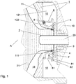
- Fig. 1 shows a schematic sectional view of that area of an exhaust gas turbocharger in which the bearing housing and an intermediate wall together adjoin and in which a shaft seal with the features described above is arranged according to the invention within the bearing housing. Shown are fixed components of the housing 1 of the turbocharger and a part of the rotor 2 with the shaft 20 guided by the bearing housing 10 in the direction of the compressor housing, and the compressor wheel 21. Inside the bearing housing 10, corresponding bearings 3 are arranged for mounting the shaft 20 can be supplied with lubricating oil by means of oil supply lines (not shown). The one in the Fig. 1 Bearing 3 shown as an example is in particular a radial bearing.
- the sealing washer 5 is part of a system for shaft sealing, by means of which it is to be prevented that lubricating oil conveyed by the bearings can get from the bearing interior towards the compressor.
- the intermediate wall 11 has an axially extending and ring-shaped ledge 111 around the rotor 2.
- a first separation gap 7 is arranged between the end face of the wall attachment 111 facing the inside of the bearing housing and the sealing disk 5.
- the large oil space 12 is separated from the seal 4 located between the rotor and the intermediate wall by this separating gap.
- the seal 4, like the sealing disk 5, belongs to the shaft seal and can be designed, for example, in the form of one or more piston rings.
- a cover 6, which extends primarily axially, according to the invention, which is limited in its primarily axial extension on the one hand by the intermediate wall 11 and on the other hand is guided in the axial direction to the seat of the sealing disk 5.
- a second separation gap 8 is arranged between the sealing disk 5 and the cover 6. Together with the sealing washer 5, the cover 6 thus divides the large oil chamber 12 into an outer oil trap chamber 121 and an inner oil trap chamber 122.
- the second separation gap 8 separates the outer oil trap chamber 121 in particular from the inner oil trap chamber 122.
- That part of the wall projection 111 which faces away from the intermediate wall 11 and the sealing disk 5 can be arranged such that lubricating oil which has entered the second separation gap 8 first enters the inner oil collecting chamber 122 instead of flowing further in the direction of the first separation gap 7.
- This oil is guided by gravity within the inner oil trap chamber 122 into the region of the inner oil trap chamber 122 which is below the rotor 2 with respect to gravity.
- In this area there is an outlet 61 through which the oil can be guided into the part of the outer oil collecting chamber 121 located below the rotor 2, and from there by means of gravity into an oil outlet of the bearing housing.
- the wall parts of the cover 6, which face the inner oil trap chamber can be made conical, at least in the region below the rotor with respect to the force of gravity, with an inclination in the direction of the outlet 61, in order to direct the oil in the direction to direct the process 61. From the oil drain of the bearing housing, the oil can finally be returned to the bearings 3 through a corresponding lubricating oil circuit.
- the outlet 61 can have the shape of an opening of the cover 6, which is arranged in a part of the region of the cover located below the rotor 2 with respect to gravity. Furthermore, the outlet 61 of the inner oil trap chamber 122 is advantageously arranged at a large axial distance from the sealing disk 5. Such an arrangement can prevent the oil to be discharged from the inner oil collecting chamber 122 through the outlet 61 from striking the sealing disk 5 and thus entering the first separating gap 7 and further in the direction of the seal 4.
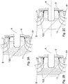
- At least one section of the cover 6 adjoining the intermediate wall can have the shape of a hollow truncated cone exhibit.
- An example of this shows Figure 2A , in which a part of the sealing section after Fig. 1 is shown.
- the largest diameter of the hollow truncated cone is expediently arranged on the end of the cover 6 facing the intermediate wall 11.
- lubricating oil collected in the inner oil collecting chamber 122 can be guided away from the sealing disk 5 in the direction of the drain 61 in the region of the inner oil collecting chamber 122 located below the rotor 2 by means of the force of gravity on the conical walls of the inner oil collecting chamber 122.
- the outlet 61 is expediently arranged in such a region of the cover 6 below the rotor which is directly adjacent to the intermediate wall 11.
- At least one section of the cover 6, which extends predominantly axially and adjoins the intermediate wall 11, has the shape of an oblique hollow cylinder.
- the axis of the oblique hollow cylinder is inclined upwards relative to the axis A of the rotor 2 in the vertical direction from the intermediate wall 11 in the direction of the bearing housing 10.
- This shape in turn allows lubricating oil collected within the inner oil collecting chamber 122 to be transported in the lower region of the inner oil collecting chamber 122 along its walls away from the sealing disk 5 in the direction of the drain 61.
- the cover 6 can be pressed, screwed or welded onto the intermediate wall 11.
- a heavy-duty spring pin can also be used to align the cover 6, for example.
- An example of the alignment of the cover 6 by a heavy-duty spring pin 9 is in particular that Fig. 1 refer to.
- the section through the cover 6 in a plane perpendicular to the axis A of the rotor 2 can take the form of at least one partial ring or a full ring.
- the sealing disk 5 and the cover 6 in the area facing each other can each be one of the following with reference to FIG Figure 1 , and then with reference to the Figures 3A, 3B and 3C have described forms.
- the cover 6 has a first axially extended section and a second axially extended section.
- the first axially extending section extends from the intermediate wall 11 in the direction of the sealing disk 5 into the large oil chamber 12.
- the second axially extending section has a greater radial distance from the axis A of the shaft 11 and shields the outer edge of the sealing disk 5 radially from the outside.
- the outer edge of the sealing disk 5 can also be understood to mean the outer surface of the sealing disk 5.
- a connection between the end of the first axially extending section facing away from the intermediate wall 11 and the second axially extending section is provided by a section of the cover 6 which extends radially along the sealing disk 5.
- the second separating gap 8 is arranged between the sealing disk 5 and the parts of the cover 6 adjacent to the sealing disk.
- this second separation gap 8 has a radially extended part 81 and an axially extended part 82.
- the second axially extended part of the cover 6 makes the axially extended part 82 of the second separation gap particularly radial from the outer oil-collecting chamber 121 shielded.
- the second axially extended section of the cover 6 can have, for example, the shape of a roof or beak that shields the axially extended part 82 of the separating gap 8 radially outwards.
- the chamfer can also be so marked on the end of the cover 6 facing away from the intermediate wall 11 be that oil impinging in this area is directed away from the second sealing gap 8 and thus away from the sealing parts in a favorable manner.
- the form of the cover 6 described above is particularly in the Fig. 1 shown.
- Figures 3A, 3B and 3C Other options for the design of the sealing disk 5 and cover 6 in the area where these components face each other are Figures 3A, 3B and 3C refer to.
- the shape of the cover 6 is chosen such that the sealing washer 5 is shielded radially outwards by a corresponding axially extending section of the cover 6.
- this shielding is realized in that the corresponding axially extending section of the cover 6 has a wedge shape, to which the corresponding radially extending section of the sealing disk 5 is also adapted in a wedge shape.
- Figure 3B shows a further possibility of radial shielding of the sealing disk 5 by a corresponding section of the cover 6.
- the cover 6 extends axially in the area shown.
- the thickness of the cover 6 measured in the radial direction initially assumes a value d1.
- the thickness of the cover 6 abruptly decreases to a thickness d2. This is done in such a way that the sealing disk 5 is shielded in the radial direction from the section of the cover 6 with the second thickness d2.
- a radially extending part 81 of the second separating gap 8 is arranged between the sealing washer 5 and that area of the cover 6 at which the thickness of the cover 6 changes abruptly from d1 to d2.
- FIG 3C is a further education of the in Figure 3B shown radial shielding of the sealing washer 5 through the cover 6.
- the thickness of the cover 6, measured in the radial direction, is reduced in this case from the direction of the intermediate wall 11 in two steps, from a thickness d1 to a thickness d2 to a thickness d3.
- the sealing disk 5 adapts to the course of the cover 6 in the corresponding region, in that the radius of the sealing disk 5 measured from the axis A of the rotor jumps from a first smaller value r1 in the axial direction from the intermediate wall to a second larger value r2 changes.
- That part of the lateral surface of the sealing disk 5 which is at a radial distance r1 from the axis A of the rotor is radially outward through the axially extending region of the cover 6 shielded with thickness d2.
- that part of the lateral surface of the sealing disk 5 which is at a radial distance r2 from the axis A of the rotor is shielded radially outwards by the axially extending region of the cover 6 with a thickness d3.
- the second separation gap 8 between the cover 6 and the sealing washer 5 thus has a configuration Figure 3C two radially extending sections and two axially extending sections.
- the sealing washer 5 can have a correspondingly smooth, i.e. may have smoothed or coated surface.
- the surface of the sealing washer should not be chosen too rough, since otherwise a great loss of friction can take place due to air located in the second separation gap 8.
- the region of the separating gap 8 adjoining the inner oil collecting chamber 122 has a radial extension component. Such a radial extension component can create a suction effect in the associated area of the separation gap 8 when the sealing disk rotates, through which lubricating oil is conveyed outward in the radial direction.
- the cover 6 in the case of in the Figures 3B and 3C Shown possible shapes of the cover 6 in the area in which the sealing washer 5 and the cover 6 face each other, the cover can continue one in the Figures 3B and 3C Not shown, the outer oil trap chamber 121 facing chamfer.
- This chamfer can in turn be so pronounced that oil impinging in the chamfer is advantageously directed away from the second sealing gap 8 and thus away from the sealing parts.
- the chamfer can take a similar form to the corresponding one in the Fig. 1 , 2A, 2B and 2C bevel shown.
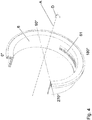
- Fig. 4 is a schematic isometric sectional view of the cover 6, seen from the bearing housing side.
- the shape of the cover 6 shown corresponds to that in the Fig. 1 is shown in section.
- an outlet 61 in the form of an opening of the cover.
- This opening extends in a plane perpendicular to the axis A of the rotor from the vertical in the Direction of rotation D of the rotor measured in a range from 90 ° to 180 °. That is, the opening is offset from the lowest point of the cover with respect to gravity, counter to the direction of rotation D of the rotor.
- the opening of the cover 6 is arranged in this case so that oil thrown tangentially into the interior of the bearing housing and bouncing off the walls cannot be reflected through the opening of the outlet 61 into the inner oil collecting chamber.
Description
Die Erfindung bezieht sich auf das Gebiet von Abgasturboladern.The invention relates to the field of exhaust gas turbochargers.
Sie betrifft eine Vorrichtung zum Abdichten eines Schmieröl aufnehmenden Lagergehäuses eines Abgasturboladers sowie einen Abgasturbolader mit einer solchen Vorrichtung.It relates to a device for sealing a bearing housing of an exhaust gas turbocharger that absorbs lubricating oil, and to an exhaust gas turbocharger with such a device.
Ein Abgasturbolader nutzt die Verbrennungsgase eines Verbrennungsmotors um die dem Verbrennungsmotor zuzuführende Verbrennungsluft zu verdichten. Durch die erreichte Vorverdichtung bzw. Aufladung der Verbrennungsluft lassen sich die Füllmenge und damit auch das Kraftstoffgemisch in den Zylindern des Motors erhöhen. Infolgedessen kann eine deutliche Steigerung der Motorleistung erzielt werden. Der in diesem Zusammenhang eingesetzte Abgasturbolader setzt sich standardmäßig aus einem Rotor mit Turbinenrad, Verdichterrad, sowie einer diese Bauteile miteinander verbindenden Welle, einer Lagerung, und feststehenden Gehäuseteilen, wie Turbinen-, Lager- und Verdichtergehäuse, zusammen. Turbinen- und Verdichtergehäuse nehmen jeweils das Turbinenrad bzw. das Verdichterrad auf und sind mit einem Massenstrom belastbar. Das Lagergehäuse grenzt einerseits an das Turbinengehäuse und andererseits an das Verdichtergehäuse, und nimmt die Welle, sowie die zugehörige Lagerung der Welle auf. Die turbinenseitig sowie verdichterseitig herrschenden zumeist hohen Prozessdrücke übersteigen den innerhalb des Lagergehäuses typischerweise vorliegenden Atmosphärendruck. Um das Innenplenum des Lagergehäuses gegenüber einem Massenstrom von Turbinen- bzw. Verdichterseite her abzudichten, werden deshalb entsprechende Dichtvorrichtungen in den Bereichen des Lagergehäuses eingesetzt, in denen die Welle durch die Lagergehäusewandungen hindurch in das Verdichter- bzw. Turbinengehäuse geführt ist.An exhaust gas turbocharger uses the combustion gases of an internal combustion engine to compress the combustion air to be supplied to the internal combustion engine. As a result of the pre-compression or charging of the combustion air, the filling quantity and thus the fuel mixture in the cylinders of the engine can be increased. As a result, a significant increase in engine performance can be achieved. The exhaust gas turbocharger used in this context is composed as standard of a rotor with a turbine wheel, compressor wheel, as well as a shaft connecting these components, a bearing, and fixed housing parts, such as turbine, bearing and compressor housing. Turbine and compressor housings each hold the turbine wheel and the compressor wheel and can be loaded with a mass flow. The bearing housing borders on the one hand on the turbine housing and on the other hand on the compressor housing, and accommodates the shaft and the associated bearing of the shaft. The mostly high process pressures prevailing on the turbine side and on the compressor side exceed the atmospheric pressure typically present within the bearing housing. In order to seal the inner plenum of the bearing housing against a mass flow from the turbine or compressor side, corresponding sealing devices are therefore used in the areas of the bearing housing in which the shaft is guided through the bearing housing walls into the compressor or turbine housing.
Zur Schmierung der Lager innerhalb des Lagergehäuses wird Schmieröl verwendet, dem darüber hinaus auch eine Kühlfunktion gegenüber den typischerweise hohen turbinenseitigen Betriebstemperaturen zukommen kann. Die Dichtvorrichtungen dienen damit auch dazu, einen Austritt von Schmieröl in das Verdichtergehäuse oder das Turbinengehäuse zu verhindern.Lubricating oil is used to lubricate the bearings within the bearing housing, which can also have a cooling function compared to the typically high turbine-side operating temperatures. The sealing devices serve thus also to prevent lubricant oil from escaping into the compressor housing or the turbine housing.
Die bei Abgasturboladern zum Einsatz kommenden Dichtungen umfassen innerhalb des Lagergehäuses angeordnete Ölfangkammersysteme sowie Kolbenringe, und dienen der Abdichtung der aus dem Lagergehäuse herausgeführten Wellenpartie gegenüber dem Lagergehäuseinneren. Diese Wellendichtsysteme verfügen typischerweise zusätzlich über ein Sperrluftsystem zur Kühlung sowie zur Sperrung gegen turbinenseitige Abgase und damit zur Verhinderung von Schmutzbildung innerhalb des Lagergehäuses. Weiterhin können zu Kühlzwecken Ölspritzbohrungen im Bereich der Wellendichtsysteme angebracht sein.The seals used in exhaust gas turbochargers include oil trap chamber systems and piston rings arranged within the bearing housing and serve to seal the shaft section led out of the bearing housing from the interior of the bearing housing. These shaft sealing systems typically also have a sealing air system for cooling and for blocking against turbine-side exhaust gases and thus for preventing dirt from forming inside the bearing housing. Furthermore, oil spray holes can be provided in the area of the shaft sealing systems for cooling purposes.
Die Lagerung eines Abgasturboladers weist standardmäßig zwei Radiallager und ein Axiallager auf. Jedem dieser Lager wird durch entsprechende Ölzufuhrleitungen Schmieröl zugeführt, welches daraufhin durch das jeweilige Lager in den Lagerraum, d.h. den gesamten Innenraum des Lagergehäuses, gefördert wird. Die Mengen des jeweils geförderten Schmieröls sowie die Geschwindigkeiten, mit denen das Schmieröl jeweils in den Lagerraum geschleudert wird, sind zum Teil erheblich. Dies hat eine Benetzung der gesamten Innenwände des Lagergehäuses mit Schmieröl zur Folge. Weiterhin kann von den Lagern gefördertes und in den Lagerraum geschleudertes Schmieröl auch an den Wandpartien des Lagergehäuses abprallen. Ein Teil dieses Schmieröls kann bei ungünstigem Abprall von den Lagergehäusewänden in den Bereich der Dichtpartien des Lagergehäuses reflektiert werden und dort zu Undichtheiten führen. Diese Problematik ist insbesondere relevant, wenn der zur Verfügung stehende Lagerraum innerhalb des Lagergehäuses klein ist. Je kleiner der Abstand zwischen den Wänden und den Dichtpartien ist, desto wahrscheinlich ist eine Reflektion von Schmieröl in den Bereich der Wellendichtung. Entsprechend sind die Anforderungen an die Wellendichtungen umso größer, je kleiner der Lagerraum ist.The bearing of an exhaust gas turbocharger has two radial bearings and one axial bearing as standard. Lubricating oil is supplied to each of these bearings through corresponding oil supply lines, which then passes through the respective bearing into the storage room, i.e. the entire interior of the bearing housing is promoted. The quantities of lubricating oil that are conveyed and the speeds at which the lubricating oil is thrown into the storage space are sometimes considerable. This results in the entire inner walls of the bearing housing being wetted with lubricating oil. Furthermore, lubricating oil delivered by the bearings and thrown into the storage room can also bounce off the wall parts of the bearing housing. In the event of an unfavorable rebound, some of this lubricating oil can be reflected from the bearing housing walls in the area of the sealing parts of the bearing housing and lead to leaks there. This problem is particularly relevant when the available storage space within the bearing housing is small. The smaller the distance between the walls and the sealing sections, the more likely it is that lubricating oil will reflect into the area of the shaft seal. Accordingly, the smaller the storage space, the greater the demands on the shaft seals.
Insbesondere relevant im Hinblick auf Undichtigkeiten der Wellendichtpartien ist der jeweilige Bereich des Ölablaufs der Wellendichtsysteme. Gegenüber den relativ kleinen Eintrittsspalten für Schmieröl in das Innere des Lagergehäuses sind die Flächen, an denen das Schmieröl abläuft groß. Durch ungünstige Reflektionen von Schmieröl an diesen großen Ablaufflächen kann Schmieröl in den Bereich der Dichtpartie geschleudert werden, so dass es zu Undichtigkeiten kommen kann.The respective area of the oil drainage of the shaft sealing systems is particularly relevant with regard to leaks in the shaft sealing parts. Compared to the relatively small entry gaps for lubricating oil into the interior of the bearing housing, the areas on which the lubricating oil runs off are large. Due to unfavorable reflections from lubricating oil In these large drainage areas, lubricating oil can be thrown into the area of the sealing section so that leaks can occur.
In
Im Zusammenhang der Erfindung wird auf Öl innerhalb des Lagergehäuses Bezug genommen, das eine Schmierfunktion übernimmt. Darüber hinaus kann dieses Öl auch eine Kühlfunktion gegenüber hohen Prozesstemperaturen auf Turbinen- oder Verdichterseite zukommen. Werden vorstehend und im Folgenden die Begriffe Öl oder Ölstrom verwendet, so sind diese als gleichbedeutend zu Schmieröl oder Schmierölstrom zu verstehen.In the context of the invention, reference is made to oil within the bearing housing, which performs a lubricating function. In addition, this oil can also have a cooling function against high process temperatures on the turbine or compressor side. If the terms oil or oil flow are used above and below, these are to be understood as synonymous with lubricating oil or lubricating oil flow.
Der Erfindung liegt die Aufgabe zugrunde, eine Vorrichtung zum Abdichten eines Lagergehäuses gegenüber einem Verdichtergehäuse eines Abgasturboladers anzugeben, bei der die Dichtigkeit der verdichterseitigen Wellendichtung verbessert ist. Die Erfindung betrifft auch einen Abgasturbolader mit einer solchen Vorrichtung.The invention has for its object a device for sealing a bearing housing against a compressor housing of an exhaust gas turbocharger to be specified in which the tightness of the compressor-side shaft seal is improved. The invention also relates to an exhaust gas turbocharger with such a device.
Bei der Vorrichtung gemäß der Erfindung, wie sie im Anspruch 1 definiert wird, ist in dem oben im Zusammenhang des Standes der Technik beschriebenen großen Ölraum, in welchen die auf der Welle befestigte Dichtscheibe hineinragt, zusätzlich eine in vornehmlich axialer Richtung erstreckte Abdeckung angeordnet. Gegenüber dem axial erstreckten Wandansatz der Zwischenwand ist die Abdeckung radial nach Außen versetzt und unterteilt den großen Ölraum zusammen mit der Dichtscheibe in eine innere Ölfangkammer und eine äußere Ölfangkammer. Zwischen der Dichtscheibe und der Abdeckung ist ein Trennspalt angeordnet, durch den die innere und die äußere Ölfangkammer voneinander getrennt sind. Die Abdeckung weist einen ersten vornehmlich axial erstreckten Abschnitt und einen zweiten vornehmlich axial erstreckten Abschnitt auf, wobei sich der erste vornehmlich axial erstreckte Abschnitt von der Zwischenwand in Richtung der Dichtscheibe in den großen Ölraum hinein erstreckt, wobei der zweite vornehmlich axial erstreckte Abschnitt einen größeren radialen Abstand von der Achse des Rotors aufweist als der erste vornehmlich axial erstreckte Abschnitt und den äußeren Rand der Dichtscheibe radial von außen abschirmt, wobei der erste und der zweite vornehmlich axial erstreckte Abschnitt durch einen vornehmlich radial erstrecken Abschnitt der Abdeckung miteinander verbunden sind, und wobei ein zweiter Trennspalt zwischen der Dichtscheibe und dem vornehmlich radial erstreckten Abschnitt sowie dem zweiten vornehmlich axial erstreckten Abschnitt der Abdeckung angeordnet ist. Durch diese Anordnung der Abdeckung wird erreicht, dass ein Großteil des von den Lagern in Richtung des großen Ölraumes geförderten Schmieröls in der äußeren Ölfangkammer abgefangen und in Richtung eines Ölablaufs des Lagergehäuses transportiert werden kann, ohne dass dieses Schmieröl in Richtung der Dichtpartie und insbesondere in den Trennspalt zwischen Wandansatz und Dichtscheibe gelangen kann. Damit wird insbesondere auch verhindert, dass eine zu große Menge Öls in den Bereich der Kolbenringe und von dort aus in den Verdichterkanal gelangen kann.In the device according to the invention, as defined in
Um in die innere Ölfangkammer eingetretenes Öl abzuführen, ist in der Abdeckung im bezüglich der Schwerkraft unterhalb der Welle befindlichen Sektor eine Öffnung angeordnet. Die dem Ölabfluß aus der inneren Ölfangkammer dienende Öffnung kann gegenüber dem, bezüglich der Schwerkraft, "tiefsten Punkt" der Abdeckung bzw. der durch die Abdeckung umschlossenen inneren Ölfangkammer, entgegen der Drehrichtung des Rotors versetzt angeordnet sein. Das heißt, die Öffnung kann sich in der senkrecht zur Drehachse der Welle befindlichen Ebene in einem von der Vertikalen aus in Drehrichtung des Rotors gemessenen Winkelbereich von 90° bis 180° erstrecken. Unter dem "tiefsten Punkt" der Abdeckung ist dabei derjenige Punkt der Abdeckung zu verstehen, der von der Vertikalen aus gemessen bei einem Winkel von 180° angeordnet ist. Mit anderen Worten kann die Öffnung der Abdeckung 6 in einer durch Vertikale und Waagerechte aufgespannten Ebene senkrecht zur vom Lagergehäuse zum Verdichtergehäuse erstreckten Achse (A) des Rotors (2) von der Vertikalen aus in Drehrichtung des Rotors gemessen in einem Bereich von 90° bis 180° angeordnet sein. Bei einer solchen Anordnung der Öffnung wird die Dichtpartie vorteilhaft gegen solches Schmieröl abgeschirmt, das im unterhalb des Rotors befindlichen Bereich der äußeren Ölfangkammer von den Wänden in Richtung des Rotors reflektiert wird.In order to discharge oil that has entered the inner oil-collecting chamber, an opening is arranged in the cover in the sector located below the shaft with respect to gravity. The opening serving the oil drain from the inner oil collecting chamber can be arranged offset from the direction of rotation of the rotor with respect to the "lowest point" of the cover with respect to gravity or the inner oil collecting chamber enclosed by the cover. This means that the opening can extend in the plane perpendicular to the axis of rotation of the shaft in an angular range from 90 ° to 180 ° measured from the vertical in the direction of rotation of the rotor. The "deepest point" of the cover is to be understood as the point of the cover which, measured from the vertical, is arranged at an angle of 180 ° is. In other words, the opening of the
Weitere Vorteile der Erfindung ergeben sich aus den abhängigen Ansprüchen.Further advantages of the invention result from the dependent claims.
Anhand von Figuren ist nachfolgend ein Ausführungsbeispiel einer Vorrichtung zum Abdichten eines Schmieröl aufnehmenden Lagergehäuses nach der Erfindung dargestellt und näher erläutert. In den Figuren sind Elemente mit gleicher Wirkung mit gleichen Bezugszeichen versehen. Es zeigt
- Fig.1
- eine schematische Schnittdarstellung der verdichterseitigen Dichtpartie mit einer Abdeckung nach der Erfindung,
- Fig. 2A
- einen Teilbereich der Dichtpartie nach
Fig. 1 mit einer Abdeckung, welche einen Abschnitt in Form eines hohlen Kegelstumpfes aufweist, - Fig. 2B
- einen Teilbereich der Dichtpartie nach
Fig. 1 mit einer Abdeckung, welche einen Abschnitt in Form eines schiefen Hohlzylinders aufweist, - Fig. 2C
- einen Teilbereich der Dichtpartie nach
Fig. 1 mit einer Abdeckung, welche einen Abschnitt in Form eines hohlen Zylinders aufweist, wobei die Wanddicke dieses Abschnitts sich in axialer Richtung von der Dichtscheibe in Richtung der Zwischenwand zum Verdichtergehäuse hin verjüngt, - Fig. 3A
- eine schematische Darstellung von Abdeckung und Dichtscheibe in demjenigen Bereich, in dem diese Bauteile aneinander angrenzen,
- Fig. 3B
- eine weitere schematische Darstellung einer möglichen Anordnung von Abdeckung und Dichtscheibe in demjenigen Bereich, in dem diese Bauteile aneinander angrenzen,
- Fig. 3C
- eine Weiterentwicklung der Anordnung der Bauteile nach
Fig. 3B , und - Fig. 4
- eine schematische isometrische Schnittdarstellung der Abdeckung mit Ablauf für innerhalb der inneren Ölfangkammer gesammeltes Schmieröl.
- Fig. 1
- 2 shows a schematic sectional illustration of the sealing section on the compressor side with a cover according to the invention,
- Figure 2A
- a part of the sealing section
Fig. 1 with a cover which has a section in the form of a hollow truncated cone, - Figure 2B
- a part of the sealing section
Fig. 1 with a cover which has a section in the form of an oblique hollow cylinder, - Figure 2C
- a part of the sealing section
Fig. 1 with a cover which has a section in the form of a hollow cylinder, the wall thickness of this section tapering in the axial direction from the sealing disk in the direction of the intermediate wall to the compressor housing, - Figure 3A
- 1 shows a schematic representation of the cover and sealing washer in the area in which these components adjoin one another,
- Figure 3B
- another schematic representation of a possible arrangement of cover and sealing washer in the area in which these components adjoin one another,
- Figure 3C
- a further development of the arrangement of the components
Figure 3B , and - Fig. 4
- is a schematic isometric sectional view of the cover with drain for lubricating oil collected within the inner oil trap chamber.
In den großen Ölraum 12 hinein ragt eine auf der Welle 20 befestigte Dichtscheibe 5. Die Dichtscheibe 5 ist Teil eines Systems zur Wellendichtung, durch welches verhindert werden soll, dass von den Lagern gefördertes Schmieröl vom Lagerinnenraum in Richtung des Verdichters gelangen kann. Die Zwischenwand 11 weist einen axial erstreckten und ringförmig um den Rotor 2 geführten Wandansatz 111 auf. Zwischen der dem Lagergehäuseinneren zugewandten Stirnseite des Wandansatzes 111 und der Dichtscheibe 5 ist ein erster Trennspalt 7 angeordnet. Durch diesen Trennspalt ist der große Ölraum 12 von der zwischen Rotor und Zwischenwand befindlichen Dichtung 4 getrennt. Die Dichtung 4 gehört, wie auch die Dichtscheibe 5, zur Wellendichtung und kann beispielsweise in Form eines oder mehrerer Kolbenringe ausgeführt sein.A sealing
In dem großen Ölraum 12 ist eine vornehmlich axial erstreckte Abdeckung 6 nach der Erfindung angeordnet, die in ihrer vornehmlich axialen Erstreckung einerseits durch die Zwischenwand 11 begrenzt ist und andererseits in axialer Richtung bis zum Sitz der Dichtscheibe 5 geführt ist. Zwischen der Dichtscheibe 5 und der Abdeckung 6 ist ein zweiter Trennspalt 8 angeordnet. Zusammen mit der Dichtscheibe 5 unterteilt die Abdeckung 6 den großen Ölraum 12 damit in eine äußere Ölfangkammer 121 und eine innere Ölfangkammer 122. Der zweite Trennspalt 8 trennt die äußere Ölfangkammer 121 insbesondere von der inneren Ölfangkammer 122.In the
Durch die Lager 3 in die äußere Ölfangkammer 121 geschleudertes Schmieröl prallt an den Wänden der äußeren Ölfangkammer 121 ab. Der Großteil dieses Schmieröls wird durch die Abdeckung 6 daran gehindert, in die innere Ölfangkammer 122 zu gelangen. Durch den zweiten Trennspalt 8 gelangt jedoch, insbesondere im bezüglich der Schwerkraft oberhalb des Rotors 2 befindlichen Bereich, ein kleiner Teil des Schmieröls von der äußeren Ölfangkammer 121 in die innere Ölfangkammer 122. Die innere Ölfangkammer 122 wird in ihrer Ausdehnung jeweils durch die Zwischenwand 11, den Wandansatz 111 der Zwischenwand, die Dichtscheibe 5, sowie die Abdeckung 6 begrenzt. Der von der Zwischenwand 11 abgewandte Teil des Wandansatzes 111 und die Dichtscheibe 5 können derart angeordnet sein, dass in den zweiten Trennspalt 8 gelangtes Schmieröl zunächst in die innere Ölfangkammer 122 gelangt, anstatt direkt weiter in Richtung des ersten Trennspalts 7 zu fließen. Dieses Öl wird mittels der Schwerkraft innerhalb der inneren Ölfangkammer 122 in den bezüglich der Schwerkraft unterhalb des Rotors 2 befindlichen Bereich der inneren Ölfangkammer 122 geleitet. In diesem Bereich ist ein Ablauf 61 angeordnet, durch den das Öl in den unterhalb des Rotors 2 befindlichen Teil der äußeren Ölfangkammer 121, und von dort aus mittels der Schwerkraft in einen Ölablauf des Lagergehäuses geführt werden kann. Wie auch im Folgenden näher beschrieben, können die Wandpartien der Abdeckung 6, welche der inneren Ölfangkammer zugewandt sind, zumindest im bezüglich der Schwerkraft unterhalb des Rotors befindlichen Bereich kegelig, mit einer Neigung in Richtung des Ablaufs 61, ausgeführt sein, um das Öl in Richtung des Ablaufs 61 zu lenken. Vom Ölablauf des Lagergehäuses kann das Öl durch einen entsprechenden Schmierölkreislauf schließlich wieder den Lagern 3 zugeführt zu werden.Lubricating oil thrown into the outer
Der Ablauf 61 kann die Form einer Öffnung der Abdeckung 6 aufweisen, welche in einem Teil des bezüglich der Schwerkraft unterhalb des Rotors 2 befindlichen Bereichs der Abdeckung angeordnet ist. Weiterhin ist der Ablauf 61 der inneren Ölfangkammer 122 vorteilhafterweise in einem großen axialen Abstand zur Dichtscheibe 5 angeordnet. Durch eine solche Anordnung kann verhindert werden, dass das aus der inneren Ölfangkammer 122 durch den Ablauf 61 abzuführende Öl auf die Dichtscheibe 5 trifft und damit in den ersten Trennspalt 7 und weiter in Richtung der Dichtung 4 gelangen kann.The
Zur Vermeidung einer Benetzung der Dichtscheibe 5 mit Öl aus der inneren Ölfangkammer 122 im Bereich des Ablaufs 61, kann zumindest ein an die Zwischenwand angrenzender Abschnitt der Abdeckung 6 die Form eines hohlen Kegelstumpfes aufweisen. Ein Beispiel dazu zeigt
Bei einer weiteren Ausführungsform kann, wie beispielhaft der
Eine weitere, in
In allen zuvor sowie im Folgenden beschriebenen Fällen kann die Abdeckung 6 auf die Zwischenwand 11 aufgepresst, aufgeschraubt oder geschweißt sein. Auch kann beispielsweise ein Schwerspannstift zur Ausrichtung der Abdeckung 6 genutzt werden. Ein Beispiel für die Ausrichtung der Abdeckung 6 durch einen Schwerspannstift 9 ist insbesondere der
Nach Möglichkeit soll verhindert werden, dass Öl im bezüglich der Schwerkraft oberhalb der Achse A des Rotors befindlichen Bereich von den Wänden der äußeren Ölfangkammer 121 oder direkt von den Lagern kommend, direkt in den Bereich der Dichtpartie gelangen kann. Um die Wellendichtung in dieser Hinsicht weiter zu verbessern, können die Dichtscheibe 5 und die Abdeckung 6 in dem einander zugewandten Bereich jeweils eine der im Folgenden mit Bezug auf die
Die Abdeckung 6 weist einen ersten axial erstreckten Abschnitt und einen zweiten axial erstreckten Abschnitt auf. Dabei erstreckt sich der erste axial erstreckte Abschnitt von der Zwischenwand 11 in Richtung der Dichtscheibe 5 in den großen Ölraum 12 hinein. Demgegenüber weist der zweite axial erstreckte Abschnitt einen größeren radialen Abstand von der Achse A der Welle 11 auf und schirmt den äußeren Rand der Dichtscheibe 5 radial von aussen ab. Unter dem äußeren Rand der Dichtscheibe 5 kann dabei auch die Mantelfläche der Dichtscheibe 5 verstanden werden. Eine Verbindung zwischen dem der Zwischenwand 11 abgewandten Ende des ersten axial erstreckten Abschnitts und dem zweiten axial erstreckten Abschnitt ist durch einen radial entlang der Dichtscheibe 5 erstrecken Abschnitt der Abdeckung 6 gegeben. Zwischen der Dichtscheibe 5 und den der Dichtscheibe benachbarten Teilen der Abdeckung 6 ist dabei der zweite Trennspalt 8 angeordnet. Im Fall der vorbeschriebenen Form der Abdeckung 6 besitzt dieser zweite Trennspalt 8 einen radial erstreckten Teil 81 sowie einen axial erstreckten Teil 82. Durch den zweiten axial erstreckten Teil der Abdeckung 6 wird der axial erstreckte Teil 82 des zweiten Trennspalts insbesondere radial von der äußeren Ölfangkammer 121 abgeschirmt. Der zweite axial erstreckte Abschnitt der Abdeckung 6 kann dabei beispielsweise die Form eines den axial erstreckten Teil 82 des Trennspalts 8 radial nach außen abschirmenden Dachs oder Schnabels aufweisen. Auch kann die Fase an dem der Zwischenwand 11 abgewandten Ende der Abdeckung 6 so ausgeprägt sein, dass in diesem Bereich auftreffendes Öl in günstiger Weise weg von dem zweiten Dichtspalt 8 und somit weg von den Dichtpartien gelenkt wird. Die vorbeschriebene Form der Abdeckung 6 ist insbesondere in der
Weitere Möglichkeiten der Ausgestaltung von Dichtscheibe 5 und Abdeckung 6 in dem Bereich, an dem diese Bauteile einander zugewandt sind, sind den
In
In
Durch die Fliehkräfte bei Rotation der am Rotor befestigten Dichtscheibe 5 kann Schmieröl im radial erstreckten Bereich des zweiten Trennspaltes 8 radial nach außen befördert werden. Um diesen erwünschten Transport von Öl von der inneren Ölfangkammer 122 in Richtung der äußeren Ölfangkammer 121 zu unterstützen, kann die Dichtscheibe 5 eine entsprechende glatte, d.h. unter Umständen geglättete oder beschichtete, Oberfläche aufweisen. Allgemein sollte die Fläche der Dichtscheibe nicht zu rau gewählt sein, da ansonsten ein großer Reibungsverlust durch im zweiten Trennspalt 8 befindliche Luft stattfinden kann. Weiterhin kann es vorteilhaft sein, wenn der an die innere Ölfangkammer 122 angrenzende Bereich des Trennspaltes 8 eine radiale Erstreckungskomponente besitzt. Durch eine solche radiale Erstreckungskomponente kann in dem zugehörigen Bereich des Trennspaltes 8 bei Rotation der Dichtscheibe eine Sogwirkung entstehen, durch die Schmieröl in radialer Richtung nach außen befördert wird.Due to the centrifugal forces when the
Im Falle der in den
In
Bei Verwendung der Begriffe "oberhalb" und "tiefster Punkt" wird vorliegend stets auf ein Bezugssystem zurückgegriffen, in dem der Turbolader auf einer horizontalen Fläche steht und die Achse des Rotors des Turboladers damit waagerecht verläuft. Die Angaben "oberhalb" und "tiefster Punkt" sind in diesem Zusammenhang bezüglich der Vertikalen, d.h. der durch die Schwerkraft gegebenen Richtung, zu verstehen. Die tatsächliche Ausrichtung des Turboladers bei Einbau kann von der vorbeschriebenen horizontalen Ausrichtung abweichen.When the terms “above” and “lowest point” are used, a reference system is always used in which the turbocharger is on a horizontal surface and the axis of the rotor of the turbocharger thus runs horizontally. The information "above" and "lowest point" are to be understood in this context with respect to the vertical, ie the direction given by gravity. The actual orientation of the turbocharger when installed may differ from the horizontal orientation described above.
- AA
- DrehachseAxis of rotation
- DD
- Drehrichtung des RotorsDirection of rotation of the rotor
- 11
- Gehäusecasing
- 1010th
- LagergehäuseBearing housing
- 1111
- ZwischenwandPartition
- 1212
- großer Ölraumlarge oil room
- 1313
- RadrückraumRear wheel space
- 111111
- WandansatzWall attachment
- 121121
- äußere Ölfangkammerouter oil trap
- 122122
- innere Ölfangkammerinner oil trap
- 22nd
- Rotorrotor
- 2020th
- Wellewave
- 2121st
- VerdichterradCompressor wheel
- 33rd
- Lagerwarehouse
- 44th
- Dichtungpoetry
- 55
- DichtscheibeSealing washer
- 66
- Abdeckungcover
- 6161
- Ablauf der inneren ÖlfangkammerDrainage from the inner oil trap chamber
- 77
- erster Trennspaltfirst separation gap
- 88th
- zweiter Trennspaltsecond separation gap
- 8181
- radial erstreckter Teil des zweiten Trennspaltsradially extending part of the second separation gap
- 8282
- axial erstreckter Teil des zweiten Trennspaltsaxially extending part of the second separation gap
- 99
- SchwerspannstiftHeavy duty pin
- d1d1
- erste Dicke der Abdeckungfirst thickness of the cover
- d2d2
- zweite Dicke der Abdeckungsecond thickness of the cover
- d3d3
- dritte Dicke der Abdeckungthird thickness of the cover
- r1r1
- erster, kleinerer Radius der Dichtscheibefirst, smaller radius of the sealing washer
- r2r2
- zweiter, größerer Radius der Dichtscheibesecond, larger radius of the sealing washer
Claims (7)
- Device for sealing a bearing housing (10), which accommodates lubricating oil, of an exhaust-gas turbocharger having a rotor (2) which is guided through the bearing housing into an adjoining compressor housing which can be charged with a mass flow, comprising
an intermediate wall (11) which separates a large oil space (12), surrounded by the bearing housing, and a wheel-rear-side chamber (13) of the compressor housing from one another and which has an axially extending wall projection (111) which is led annularly around the rotor,
an annular sealing disc (5) which is fastened to a shaft (20) of the rotor (2) and which protrudes into the large oil space (12),
a first parting gap (7) which is arranged between the sealing disc (5) and the wall projection (111), a seal (4) arranged between rotor (2) and intermediate wall (11),
wherein a predominantly axially extending cover (6) is arranged in the large oil space (12), wherein the cover is offset radially outwards in relation to the axially extending wall projection (111) and, together with the sealing disc (5), divides the large oil space (12) into an inner oil-collecting chamber (122) and an outer oil-collecting chamber (121), characterized in that the cover (6) has a first predominantly axially extending portion and a second predominantly axially extending portion, wherein the first predominantly axially extending portion extends from the intermediate wall (11) in the direction of the sealing disc (5) into the large oil space (12), wherein the second predominantly axially extending portion has a greater radial spacing to the axis (A) of the rotor (20) than the first predominantly axially extending portion and shields the outer edge of the sealing disc (5) radially from the outside, wherein the first and the second predominantly axially extending portion are connected to one another by a predominantly radially extending portion of the cover (6), and wherein a second parting gap (8) is arranged between the sealing disc (5) and the predominantly radially extending portion and the second predominantly axially extending portion of the cover (6). - Device according to Claim 1, characterized in that the cover (6) has an outlet (61) in the sector which is situated below the rotor with respect to a horizontal orientation of the axis (A) of the rotor (2), wherein the outlet is designed in the form of an opening of the cover and serves for discharging lubricating oil that has collected within the inner oil-collecting chamber (122).
- Device according to Claim 2, characterized in that the outlet (61) of the inner oil-collecting chamber (122) is arranged offset, counter to the direction of rotation of the rotor (2), in relation to the lowest point, with respect to gravitational force, of the inner oil-collecting chamber (122).
- Device according to Claim 1, characterized in that the cover (6) is pressed onto the intermediate wall (11), and/or is aligned by means of a heavy type dowel pin (9) and/or is led in at least partially annular fashion around the rotor (2).
- Device according to Claim 2, characterized in that a portion, adjoining the intermediate wall (11), of the predominantly axially extending cover (6) has the shape of a hollow frustum, wherein the axis of the hollow frustum coincides with the axis (A) of the rotor (2), wherein the greatest diameter of the hollow frustum is situated at that end of the cover which faces towards the intermediate wall (11), and wherein the outlet (61) for lubricating oil that has collected in the inner oil-collecting chamber is arranged axially offset from the sealing disc (5) in the direction of the intermediate wall (11).
- Device according to Claim 2, characterized in that a portion, adjoining the intermediate wall (11), of the predominantly axially extending cover (6) has the shape of an oblique hollow cylinder, wherein the axis of the oblique hollow cylinder is inclined upwards in relation to the axis (A) of the rotor (2) in the direction of the vertical as viewed from the intermediate wall (11) in the direction of the bearing housing (10).
- Exhaust-gas turbocharger having a device according to any of Claims 1 to 7.
Applications Claiming Priority (2)
| Application Number | Priority Date | Filing Date | Title |
|---|---|---|---|
| DE102015119602.6A DE102015119602A1 (en) | 2015-11-13 | 2015-11-13 | shaft seal |
| PCT/EP2016/076688 WO2017080924A1 (en) | 2015-11-13 | 2016-11-04 | Device for sealing off a bearing housing, and exhaust-gas turbocharger having a device of said type |
Publications (2)
| Publication Number | Publication Date |
|---|---|
| EP3374602A1 EP3374602A1 (en) | 2018-09-19 |
| EP3374602B1 true EP3374602B1 (en) | 2020-05-20 |
Family
ID=57223717
Family Applications (1)
| Application Number | Title | Priority Date | Filing Date |
|---|---|---|---|
| EP16790406.9A Active EP3374602B1 (en) | 2015-11-13 | 2016-11-04 | Arrangement for sealing a bearing casing and exhaust gas turbocharger comprising such arrangement |
Country Status (6)
| Country | Link |
|---|---|
| EP (1) | EP3374602B1 (en) |
| JP (1) | JP6868620B2 (en) |
| KR (1) | KR102646179B1 (en) |
| CN (1) | CN108474266B (en) |
| DE (1) | DE102015119602A1 (en) |
| WO (1) | WO2017080924A1 (en) |
Families Citing this family (2)
| Publication number | Priority date | Publication date | Assignee | Title |
|---|---|---|---|---|
| DE102017202687A1 (en) | 2017-02-20 | 2018-08-23 | BMTS Technology GmbH & Co. KG | Bearing housing and a Abgasturoblader with such a housing |
| FR3090786B1 (en) * | 2018-12-21 | 2020-12-04 | Safran Trans Systems | LUBRICATING OIL DISPENSER FOR AN AIRCRAFT TURBOMACHINE MECHANICAL REDUCER |
Family Cites Families (13)
| Publication number | Priority date | Publication date | Assignee | Title |
|---|---|---|---|---|
| DE1077007B (en) * | 1958-11-14 | 1960-03-03 | Daimler Benz Ag | Arrangement of the bearings of shafts or the like rotating machine parts |
| JPH0216037Y2 (en) * | 1984-12-20 | 1990-05-01 | ||
| JP3252046B2 (en) * | 1994-02-02 | 2002-01-28 | 大豊工業株式会社 | Non-contact sealing device for turbocharger |
| JPH07217441A (en) * | 1994-02-02 | 1995-08-15 | Taiho Kogyo Co Ltd | Noncontact seal device for turbocharger |
| JPH08135458A (en) * | 1994-11-09 | 1996-05-28 | Toyota Motor Corp | Oil seal structure for supercharger |
| JPH09264151A (en) * | 1996-03-29 | 1997-10-07 | Aisin Seiki Co Ltd | Oil leak preventing mechanism for turbo charger |
| GB0720478D0 (en) * | 2007-10-13 | 2007-11-28 | Cummins Turbo Tech Ltd | Turbomachine |
| DE502008002335D1 (en) * | 2008-11-28 | 2011-02-24 | Abb Turbo Systems Ag | Device for sealing a bearing housing of an exhaust gas turbocharger |
| GB2469101B (en) * | 2009-04-02 | 2015-10-21 | Cummins Turbo Tech Ltd | A rotating machine with shaft sealing arrangement |
| WO2013145078A1 (en) * | 2012-03-26 | 2013-10-03 | トヨタ自動車 株式会社 | Exhaust turbine supercharger |
| EP2872753B1 (en) * | 2012-07-15 | 2019-03-20 | Garrett Transportation I Inc. | Turbocharger with lubricant deflector |
| DE102013202841A1 (en) * | 2013-02-21 | 2014-08-21 | Bosch Mahle Turbo Systems Gmbh & Co. Kg | turbocharger |
| CN204402646U (en) * | 2014-12-04 | 2015-06-17 | 湖南天雁机械有限责任公司 | Compressor end sealing structure of turbosuperchargers |
-
2015
- 2015-11-13 DE DE102015119602.6A patent/DE102015119602A1/en not_active Withdrawn
-
2016
- 2016-11-04 JP JP2018524426A patent/JP6868620B2/en active Active
- 2016-11-04 WO PCT/EP2016/076688 patent/WO2017080924A1/en active Application Filing
- 2016-11-04 CN CN201680078972.XA patent/CN108474266B/en active Active
- 2016-11-04 KR KR1020187016571A patent/KR102646179B1/en active IP Right Grant
- 2016-11-04 EP EP16790406.9A patent/EP3374602B1/en active Active
Non-Patent Citations (1)
| Title |
|---|
| None * |
Also Published As
| Publication number | Publication date |
|---|---|
| WO2017080924A1 (en) | 2017-05-18 |
| CN108474266A (en) | 2018-08-31 |
| EP3374602A1 (en) | 2018-09-19 |
| CN108474266B (en) | 2020-10-23 |
| JP6868620B2 (en) | 2021-05-12 |
| JP2018533689A (en) | 2018-11-15 |
| KR102646179B1 (en) | 2024-03-12 |
| KR20180075675A (en) | 2018-07-04 |
| DE102015119602A1 (en) | 2017-05-18 |
Similar Documents
| Publication | Publication Date | Title |
|---|---|---|
| EP2375000B2 (en) | Shaft seal | |
| EP2192272B1 (en) | Device for sealing a bearing box of a turbocharger | |
| DE102015117773A1 (en) | Jet engine with several chambers and a bearing chamber carrier | |
| DE112008002730T5 (en) | Device for preventing an oil flow along a rotating shaft | |
| DE112013002029T5 (en) | Centrifugal oil seal and turbocharger with centrifugal oil seal | |
| DE102017202687A1 (en) | Bearing housing and a Abgasturoblader with such a housing | |
| EP3267089A1 (en) | Oil distribution system and turbomaschine having an oil distribution system | |
| EP3374602B1 (en) | Arrangement for sealing a bearing casing and exhaust gas turbocharger comprising such arrangement | |
| DE102011017052A1 (en) | Compressor housing of a centrifugal compressor | |
| DE102013202841A1 (en) | turbocharger | |
| EP2730744B1 (en) | Exhaust gas turbo charger | |
| EP2772652B1 (en) | Partition for sealing the rear section of a radial compressor | |
| EP2054629B1 (en) | Shaft seal | |
| DE112016003653B4 (en) | Bearing structure and turbocharger | |
| DE202014002981U1 (en) | Axial turbine for an exhaust gas turbocharger | |
| WO2014131413A1 (en) | Sealing arrangement for a turbocharger shaft of an exhaust gas turbocharger | |
| DE102021209885A1 (en) | Planetary gear set and transmission for a motor vehicle | |
| DE202017100779U1 (en) | Oil separator with split drive chamber | |
| EP2743460B1 (en) | Shaft seal | |
| EP3371420B1 (en) | Arrangement for separation of lubricant flows and exhaust gas turbocharger comprising such arrangement | |
| EP3867501B1 (en) | Exhaust gas turbocharger with improved shaft seal | |
| DE102016217286A1 (en) | pressure vessel | |
| DE102016004770A1 (en) | Stop assembly, intake and exhaust system and vehicle comprising such a system | |
| DE102020105746A1 (en) | TURBOCHARGER WITH MULTI-STAGE BORE | |
| EP3601739A1 (en) | Turbocharger for an internal combustion engine, and turbine housing |
Legal Events
| Date | Code | Title | Description |
|---|---|---|---|
| STAA | Information on the status of an ep patent application or granted ep patent |
Free format text: STATUS: UNKNOWN |
|
| STAA | Information on the status of an ep patent application or granted ep patent |
Free format text: STATUS: THE INTERNATIONAL PUBLICATION HAS BEEN MADE |
|
| PUAI | Public reference made under article 153(3) epc to a published international application that has entered the european phase |
Free format text: ORIGINAL CODE: 0009012 |
|
| STAA | Information on the status of an ep patent application or granted ep patent |
Free format text: STATUS: REQUEST FOR EXAMINATION WAS MADE |
|
| 17P | Request for examination filed |
Effective date: 20180613 |
|
| AK | Designated contracting states |
Kind code of ref document: A1 Designated state(s): AL AT BE BG CH CY CZ DE DK EE ES FI FR GB GR HR HU IE IS IT LI LT LU LV MC MK MT NL NO PL PT RO RS SE SI SK SM TR |
|
| AX | Request for extension of the european patent |
Extension state: BA ME |
|
| DAV | Request for validation of the european patent (deleted) | ||
| DAX | Request for extension of the european patent (deleted) | ||
| GRAP | Despatch of communication of intention to grant a patent |
Free format text: ORIGINAL CODE: EPIDOSNIGR1 |
|
| STAA | Information on the status of an ep patent application or granted ep patent |
Free format text: STATUS: GRANT OF PATENT IS INTENDED |
|
| INTG | Intention to grant announced |
Effective date: 20191213 |
|
| GRAS | Grant fee paid |
Free format text: ORIGINAL CODE: EPIDOSNIGR3 |
|
| GRAA | (expected) grant |
Free format text: ORIGINAL CODE: 0009210 |
|
| STAA | Information on the status of an ep patent application or granted ep patent |
Free format text: STATUS: THE PATENT HAS BEEN GRANTED |
|
| RIN1 | Information on inventor provided before grant (corrected) |
Inventor name: VACCA, ANDREA Inventor name: SCHMID, ANDREAS Inventor name: RECHIN, THOMAS |
|
| AK | Designated contracting states |
Kind code of ref document: B1 Designated state(s): AL AT BE BG CH CY CZ DE DK EE ES FI FR GB GR HR HU IE IS IT LI LT LU LV MC MK MT NL NO PL PT RO RS SE SI SK SM TR |
|
| REG | Reference to a national code |
Ref country code: GB Ref legal event code: FG4D Free format text: NOT ENGLISH |
|
| REG | Reference to a national code |
Ref country code: CH Ref legal event code: EP |
|
| REG | Reference to a national code |
Ref country code: DE Ref legal event code: R096 Ref document number: 502016010012 Country of ref document: DE |
|
| REG | Reference to a national code |
Ref country code: AT Ref legal event code: REF Ref document number: 1272731 Country of ref document: AT Kind code of ref document: T Effective date: 20200615 |
|
| RAP2 | Party data changed (patent owner data changed or rights of a patent transferred) |
Owner name: ABB SCHWEIZ AG |
|
| REG | Reference to a national code |
Ref country code: FI Ref legal event code: FGE |
|
| REG | Reference to a national code |
Ref country code: DE Ref legal event code: R081 Ref document number: 502016010012 Country of ref document: DE Owner name: TURBO SYSTEMS SWITZERLAND LTD., CH Free format text: FORMER OWNER: ABB TURBO SYSTEMS AG, BADEN, CH Ref country code: DE Ref legal event code: R082 Ref document number: 502016010012 Country of ref document: DE Representative=s name: ZIMMERMANN & PARTNER PATENTANWAELTE MBB, DE Ref country code: DE Ref legal event code: R081 Ref document number: 502016010012 Country of ref document: DE Owner name: ABB SCHWEIZ AG, CH Free format text: FORMER OWNER: ABB TURBO SYSTEMS AG, BADEN, CH |
|
| RAP2 | Party data changed (patent owner data changed or rights of a patent transferred) |
Owner name: ABB SCHWEIZ AG |
|
| REG | Reference to a national code |
Ref country code: LT Ref legal event code: MG4D |
|
| REG | Reference to a national code |
Ref country code: NL Ref legal event code: MP Effective date: 20200520 |
|
| PG25 | Lapsed in a contracting state [announced via postgrant information from national office to epo] |
Ref country code: SE Free format text: LAPSE BECAUSE OF FAILURE TO SUBMIT A TRANSLATION OF THE DESCRIPTION OR TO PAY THE FEE WITHIN THE PRESCRIBED TIME-LIMIT Effective date: 20200520 Ref country code: LT Free format text: LAPSE BECAUSE OF FAILURE TO SUBMIT A TRANSLATION OF THE DESCRIPTION OR TO PAY THE FEE WITHIN THE PRESCRIBED TIME-LIMIT Effective date: 20200520 Ref country code: PT Free format text: LAPSE BECAUSE OF FAILURE TO SUBMIT A TRANSLATION OF THE DESCRIPTION OR TO PAY THE FEE WITHIN THE PRESCRIBED TIME-LIMIT Effective date: 20200921 Ref country code: IS Free format text: LAPSE BECAUSE OF FAILURE TO SUBMIT A TRANSLATION OF THE DESCRIPTION OR TO PAY THE FEE WITHIN THE PRESCRIBED TIME-LIMIT Effective date: 20200920 Ref country code: GR Free format text: LAPSE BECAUSE OF FAILURE TO SUBMIT A TRANSLATION OF THE DESCRIPTION OR TO PAY THE FEE WITHIN THE PRESCRIBED TIME-LIMIT Effective date: 20200821 Ref country code: NO Free format text: LAPSE BECAUSE OF FAILURE TO SUBMIT A TRANSLATION OF THE DESCRIPTION OR TO PAY THE FEE WITHIN THE PRESCRIBED TIME-LIMIT Effective date: 20200820 |
|
| PG25 | Lapsed in a contracting state [announced via postgrant information from national office to epo] |
Ref country code: LV Free format text: LAPSE BECAUSE OF FAILURE TO SUBMIT A TRANSLATION OF THE DESCRIPTION OR TO PAY THE FEE WITHIN THE PRESCRIBED TIME-LIMIT Effective date: 20200520 Ref country code: RS Free format text: LAPSE BECAUSE OF FAILURE TO SUBMIT A TRANSLATION OF THE DESCRIPTION OR TO PAY THE FEE WITHIN THE PRESCRIBED TIME-LIMIT Effective date: 20200520 Ref country code: BG Free format text: LAPSE BECAUSE OF FAILURE TO SUBMIT A TRANSLATION OF THE DESCRIPTION OR TO PAY THE FEE WITHIN THE PRESCRIBED TIME-LIMIT Effective date: 20200820 Ref country code: HR Free format text: LAPSE BECAUSE OF FAILURE TO SUBMIT A TRANSLATION OF THE DESCRIPTION OR TO PAY THE FEE WITHIN THE PRESCRIBED TIME-LIMIT Effective date: 20200520 |
|
| PG25 | Lapsed in a contracting state [announced via postgrant information from national office to epo] |
Ref country code: NL Free format text: LAPSE BECAUSE OF FAILURE TO SUBMIT A TRANSLATION OF THE DESCRIPTION OR TO PAY THE FEE WITHIN THE PRESCRIBED TIME-LIMIT Effective date: 20200520 Ref country code: AL Free format text: LAPSE BECAUSE OF FAILURE TO SUBMIT A TRANSLATION OF THE DESCRIPTION OR TO PAY THE FEE WITHIN THE PRESCRIBED TIME-LIMIT Effective date: 20200520 |
|
| PG25 | Lapsed in a contracting state [announced via postgrant information from national office to epo] |
Ref country code: CZ Free format text: LAPSE BECAUSE OF FAILURE TO SUBMIT A TRANSLATION OF THE DESCRIPTION OR TO PAY THE FEE WITHIN THE PRESCRIBED TIME-LIMIT Effective date: 20200520 Ref country code: RO Free format text: LAPSE BECAUSE OF FAILURE TO SUBMIT A TRANSLATION OF THE DESCRIPTION OR TO PAY THE FEE WITHIN THE PRESCRIBED TIME-LIMIT Effective date: 20200520 Ref country code: IT Free format text: LAPSE BECAUSE OF FAILURE TO SUBMIT A TRANSLATION OF THE DESCRIPTION OR TO PAY THE FEE WITHIN THE PRESCRIBED TIME-LIMIT Effective date: 20200520 Ref country code: SM Free format text: LAPSE BECAUSE OF FAILURE TO SUBMIT A TRANSLATION OF THE DESCRIPTION OR TO PAY THE FEE WITHIN THE PRESCRIBED TIME-LIMIT Effective date: 20200520 Ref country code: EE Free format text: LAPSE BECAUSE OF FAILURE TO SUBMIT A TRANSLATION OF THE DESCRIPTION OR TO PAY THE FEE WITHIN THE PRESCRIBED TIME-LIMIT Effective date: 20200520 Ref country code: DK Free format text: LAPSE BECAUSE OF FAILURE TO SUBMIT A TRANSLATION OF THE DESCRIPTION OR TO PAY THE FEE WITHIN THE PRESCRIBED TIME-LIMIT Effective date: 20200520 Ref country code: ES Free format text: LAPSE BECAUSE OF FAILURE TO SUBMIT A TRANSLATION OF THE DESCRIPTION OR TO PAY THE FEE WITHIN THE PRESCRIBED TIME-LIMIT Effective date: 20200520 |
|
| REG | Reference to a national code |
Ref country code: DE Ref legal event code: R097 Ref document number: 502016010012 Country of ref document: DE |
|
| PG25 | Lapsed in a contracting state [announced via postgrant information from national office to epo] |
Ref country code: SK Free format text: LAPSE BECAUSE OF FAILURE TO SUBMIT A TRANSLATION OF THE DESCRIPTION OR TO PAY THE FEE WITHIN THE PRESCRIBED TIME-LIMIT Effective date: 20200520 Ref country code: PL Free format text: LAPSE BECAUSE OF FAILURE TO SUBMIT A TRANSLATION OF THE DESCRIPTION OR TO PAY THE FEE WITHIN THE PRESCRIBED TIME-LIMIT Effective date: 20200520 |
|
| REG | Reference to a national code |
Ref country code: GB Ref legal event code: 732E Free format text: REGISTERED BETWEEN 20210225 AND 20210303 |
|
| PLBE | No opposition filed within time limit |
Free format text: ORIGINAL CODE: 0009261 |
|
| STAA | Information on the status of an ep patent application or granted ep patent |
Free format text: STATUS: NO OPPOSITION FILED WITHIN TIME LIMIT |
|
| REG | Reference to a national code |
Ref country code: GB Ref legal event code: 732E Free format text: REGISTERED BETWEEN 20210304 AND 20210310 |
|
| 26N | No opposition filed |
Effective date: 20210223 |
|
| PG25 | Lapsed in a contracting state [announced via postgrant information from national office to epo] |
Ref country code: SI Free format text: LAPSE BECAUSE OF FAILURE TO SUBMIT A TRANSLATION OF THE DESCRIPTION OR TO PAY THE FEE WITHIN THE PRESCRIBED TIME-LIMIT Effective date: 20200520 |
|
| PG25 | Lapsed in a contracting state [announced via postgrant information from national office to epo] |
Ref country code: MC Free format text: LAPSE BECAUSE OF FAILURE TO SUBMIT A TRANSLATION OF THE DESCRIPTION OR TO PAY THE FEE WITHIN THE PRESCRIBED TIME-LIMIT Effective date: 20200520 |
|
| REG | Reference to a national code |
Ref country code: CH Ref legal event code: PL |
|
| PG25 | Lapsed in a contracting state [announced via postgrant information from national office to epo] |
Ref country code: LU Free format text: LAPSE BECAUSE OF NON-PAYMENT OF DUE FEES Effective date: 20201104 |
|
| REG | Reference to a national code |
Ref country code: BE Ref legal event code: MM Effective date: 20201130 |
|
| PG25 | Lapsed in a contracting state [announced via postgrant information from national office to epo] |
Ref country code: CH Free format text: LAPSE BECAUSE OF NON-PAYMENT OF DUE FEES Effective date: 20201130 Ref country code: LI Free format text: LAPSE BECAUSE OF NON-PAYMENT OF DUE FEES Effective date: 20201130 |
|
| PG25 | Lapsed in a contracting state [announced via postgrant information from national office to epo] |
Ref country code: FR Free format text: LAPSE BECAUSE OF NON-PAYMENT OF DUE FEES Effective date: 20201130 Ref country code: IE Free format text: LAPSE BECAUSE OF NON-PAYMENT OF DUE FEES Effective date: 20201104 |
|
| PG25 | Lapsed in a contracting state [announced via postgrant information from national office to epo] |
Ref country code: TR Free format text: LAPSE BECAUSE OF FAILURE TO SUBMIT A TRANSLATION OF THE DESCRIPTION OR TO PAY THE FEE WITHIN THE PRESCRIBED TIME-LIMIT Effective date: 20200520 Ref country code: MT Free format text: LAPSE BECAUSE OF FAILURE TO SUBMIT A TRANSLATION OF THE DESCRIPTION OR TO PAY THE FEE WITHIN THE PRESCRIBED TIME-LIMIT Effective date: 20200520 Ref country code: CY Free format text: LAPSE BECAUSE OF FAILURE TO SUBMIT A TRANSLATION OF THE DESCRIPTION OR TO PAY THE FEE WITHIN THE PRESCRIBED TIME-LIMIT Effective date: 20200520 |
|
| PG25 | Lapsed in a contracting state [announced via postgrant information from national office to epo] |
Ref country code: MK Free format text: LAPSE BECAUSE OF FAILURE TO SUBMIT A TRANSLATION OF THE DESCRIPTION OR TO PAY THE FEE WITHIN THE PRESCRIBED TIME-LIMIT Effective date: 20200520 |
|
| PG25 | Lapsed in a contracting state [announced via postgrant information from national office to epo] |
Ref country code: BE Free format text: LAPSE BECAUSE OF NON-PAYMENT OF DUE FEES Effective date: 20201130 |
|
| REG | Reference to a national code |
Ref country code: GB Ref legal event code: 732E Free format text: REGISTERED BETWEEN 20220922 AND 20220928 |
|
| REG | Reference to a national code |
Ref country code: DE Ref legal event code: R081 Ref document number: 502016010012 Country of ref document: DE Owner name: TURBO SYSTEMS SWITZERLAND LTD., CH Free format text: FORMER OWNER: ABB SCHWEIZ AG, BADEN, CH |
|
| REG | Reference to a national code |
Ref country code: AT Ref legal event code: MM01 Ref document number: 1272731 Country of ref document: AT Kind code of ref document: T Effective date: 20211104 |
|
| PG25 | Lapsed in a contracting state [announced via postgrant information from national office to epo] |
Ref country code: AT Free format text: LAPSE BECAUSE OF NON-PAYMENT OF DUE FEES Effective date: 20211104 |
|
| PGFP | Annual fee paid to national office [announced via postgrant information from national office to epo] |
Ref country code: GB Payment date: 20231123 Year of fee payment: 8 |
|
| PGFP | Annual fee paid to national office [announced via postgrant information from national office to epo] |
Ref country code: FI Payment date: 20231121 Year of fee payment: 8 Ref country code: DE Payment date: 20231121 Year of fee payment: 8 |