EP2374979A2 - Plug-connector - Google Patents
Plug-connector Download PDFInfo
- Publication number
- EP2374979A2 EP2374979A2 EP11160320A EP11160320A EP2374979A2 EP 2374979 A2 EP2374979 A2 EP 2374979A2 EP 11160320 A EP11160320 A EP 11160320A EP 11160320 A EP11160320 A EP 11160320A EP 2374979 A2 EP2374979 A2 EP 2374979A2
- Authority
- EP
- European Patent Office
- Prior art keywords
- connector
- connector according
- lamellae
- longitudinal side
- insertion direction
- Prior art date
- Legal status (The legal status is an assumption and is not a legal conclusion. Google has not performed a legal analysis and makes no representation as to the accuracy of the status listed.)
- Granted
Links
Images

Classifications
-
- E—FIXED CONSTRUCTIONS
- E06—DOORS, WINDOWS, SHUTTERS, OR ROLLER BLINDS IN GENERAL; LADDERS
- E06B—FIXED OR MOVABLE CLOSURES FOR OPENINGS IN BUILDINGS, VEHICLES, FENCES OR LIKE ENCLOSURES IN GENERAL, e.g. DOORS, WINDOWS, BLINDS, GATES
- E06B3/00—Window sashes, door leaves, or like elements for closing wall or like openings; Layout of fixed or moving closures, e.g. windows in wall or like openings; Features of rigidly-mounted outer frames relating to the mounting of wing frames
- E06B3/66—Units comprising two or more parallel glass or like panes permanently secured together
- E06B3/663—Elements for spacing panes
- E06B3/667—Connectors therefor
Definitions
- the invention relates to a connector with U- or box-shaped cross-section, which is designed as a straight, angled, corner or crossing connector.
- Such connectors are used in insulating glass for connecting spacer hollow profiles for insulating glass panes.
- Such a connector is provided with a bottom part and two longitudinal side edges, which may be formed as a leg rising from the ground, wherein the bottom part together with the longitudinal side edges forms the body of the connector.
- the object of the invention is to provide a connector which ensures an equal good grip even at large tolerances of the spacer hollow profile at least substantially the same contact pressure of the retaining means and thus also with different spacer hollow profiles.
- even with spacer hollow profiles should be maintained at both ends of the tolerance range as constant a force for insertion of the connector in the spacer hollow profile.
- This object is achieved in that are arranged on the longitudinal side edges outwardly projecting, elastically deformable fins for each plug-in section, which can be made inclined or bent, wherein the inclination or bending can be formed in the insertion direction to the rear.
- At least individual lamellae can be formed at least partially mutually contacting or at least partially connected to each other.
- Another very advantageous embodiment of the invention is also present if at least one stop is provided, which is able to limit the insertion length of the connector in a hollow profile, wherein the stops can be arranged on the longitudinal side edges of the connector and formed elastically.
- This resilient compensating element avoids unwanted tilting of the connector. In addition, it is ensured that the compensation element does not interfere with the sliding of the hollow profile.
- Another very advantageous development of the invention is also present when at least one barrier plate is provided together with the outwardly projecting slats, which is able to form fit to the inner sides of the hollow sections to be joined.
- This barrier lamella seals a cavity between the connector and the spacer hollow profile, for example, in the region of a butyl bead and prevents, for example, the undesired escape of a molecular sieve or desiccant at the spacer hollow profile joint.
- a very advantageous embodiment according to a further development of the invention is also provided if at least one locking lamella is provided on the bottom part, preferably between the two limbs, for each insertion direction.
- the molecular sieve flow or desiccant flow through a U-shaped connector can be prevented.
- the desiccant can not reach the joint. If more such barrier slats are provided, the seal is improved and ensures that no desiccant is able to leak, even if the connector is partially pulled out of the hollow profile, which occur during the transport of spacer hollow profile frame in the production of insulating glass alone by the weight and size of such frame can.
- the distance between the lamellae is equal to or less than the thickness of the lamellae.
- the holding elements are inclined against the insertion direction, wherein the inclination angle between 5 and 20 °, preferably between 5 and 10 ° may be.
- cross section of the holding elements is at least approximately oval or round.
- This embodiment ensures a very good Festkrallen the holding elements on the inside of the spacer hollow profile.
- Another extremely advantageous embodiment is also present when the holding elements are formed starting from the bottom tapering.
- the retaining elements can be given a desired elasticity, whereby they also adapt very well to different dimensions of the hollow profile and compensate for tolerances.
- the contact pressure remains almost constant over a wide range, which is why the connectors hold very well in the hollow profile.
- the connector is formed bevelled at its ends.
- tapered ends of the connector can be particularly safe and easily inserted into the hollow sections. A machine plugging is made easier and safer.
- a U-shaped connector with a bottom part 2 and two adjoining the longitudinal side edges 3 and 4 longitudinal side webs 5 and 6 respectively.
- a center stop 8 is likewise provided on the outer sides of the longitudinal side webs 5 and 6 for each insertion direction, which limits the insertion depth of the connector 1 into the hollow profiles.
- the center stops 8 are each assigned a compensation element 9, which is provided opposite the center stops 8 on the other longitudinal side web 5 and 6 respectively.
- the compensating element 9 is formed elastically resilient and on the one hand ensures that the hollow sections abut against the middle stops 8. On the other hand, any manufacturing tolerances of the hollow profile are compensated. A wobble of the connector 1 in the hollow profile is avoided.
- the outwardly projecting slats 7 may extend over a part or the entire height of the side webs 5 and 6 respectively.
- the lamellae 7 may be formed starting from the side bars 5 and 6, respectively, tapered.
- the taper of the slats 7 can be done stepwise or linear. Discontinuous taper profiles are also conceivable.
- the lamellae 7 have on at least a portion of their height an additional support member 10 which may be formed on a lamella 7 and ensures that this lamella 7 and the adjacent lamella 7, for example, from a predetermined bend together able to support.
- this support member 10 can also be formed so that the two fins are connected to each other at least over part of their extent.
- the support member 10 may act as a directly integrally formed on a blade 7 stiffening element, so that the blade 7 undergoes a selective change in the elasticity.
- the slats 7 are inclined in the illustrated example opposite to the insertion of the connector 1 into the hollow profile to the rear. Particularly good results in terms of the insertion force to be applied and the force required to pull out the connectors again from the hollow profile were achieved at inclinations between 45 and 60 °. Other angles of inclination are conceivable.
- the slats 7 protrude at least approximately perpendicularly from the longitudinal side webs 5 and 6 and can be bent during insertion into a hollow profile.
- the fins 7 are elastic and can each be relatively easily formed by itself. In order to ensure a sufficient hold of the connector in the hollow profile, a plurality of fins 7 is provided. These fins 7 can have a thickness of less than one millimeter. The fins 7 can also be arranged densely packed. The distance between two adjacent lamellae 7 may be smaller than the thickness thereof.
- the fins 7 in the illustrated example extend in height direction only over part of the height of the hollow section.
- This desiccant should not get to the abutting edge of the hollow profile ends to be joined, since there is the danger that the desiccant exits into the disc interior and there provides impurities that are undesirable.
- single lamellae 7 are formed as locking lamellae 7a, which are formed over the remaining lamellae 7 excessive and have a contour which is adapted to the inner contour of the hollow profile.
- the locking lamellae 7a can also be provided in addition to the lamellae 7. In order to ensure a good sealing is provided for each side bar and for each insertion direction at least one barrier plate 7a.
- Barrier plates 11 are provided. Through this barrier slats 11 a desiccant pass through the connector 1 is prevented. Even in the middle area can thus no more desiccant reach the joint of the hollow profile ends.
- the side bars 5 and 6 carry on their side facing away from the bottom surface 2 side holding means 12 which are aligned at least approximately perpendicular with respect to the bottom surface.
- These holding devices 12 have a round, oval or even angular cross-section and are formed as discrete elevations.
- the holding devices 12 can be tilted slightly counter to the insertion direction to the rear, with angles of inclination of 10 ° have proven to be very beneficial.
- the holding devices 12 are chamfered at least slightly in the insertion direction.
- the holding devices 12 are also selectively elastic and thus able to adapt to different hollow profile dimensions.
- the shape of the holding devices 12, their dimensions and their number on the one hand affects the force that must be expended in order to use the connector 1 in the respective hollow profile can. On the other hand, but also the restraining force of the connector 1 is controlled in the hollow profile.
- the contact pressure of the holding devices 12 remains at least approximately constant over this entire area.
- the holding devices 12 can be formed tapered in linear or stepwise form. Likewise, discrete stiffening elements are possible.
- the ends of the connector 1 may be formed chamfered to facilitate insertion into the hollow profile ends. A machine plugging or plugging is supported.
- the connector according to the invention can be used in all types of hollow profiles. Conceivable is the use of aluminum, steel, stainless steel, but also plastic profiles.
- the connectors 1 may be made of plastic, fiber reinforced plastic, aluminum, metal or steel. Other materials are conceivable.
- the use of the connector 1 is conceivable in all formats of insulating glass panes.
- the retention force is great even for large shop windows
Landscapes
- Engineering & Computer Science (AREA)
- Civil Engineering (AREA)
- Structural Engineering (AREA)
- Securing Of Glass Panes Or The Like (AREA)
- Connector Housings Or Holding Contact Members (AREA)
- Connection Of Plates (AREA)
Abstract
Description
Die Erfindung bezieht sich auf einen Steckverbinder mit U- oder kastenförmigem Querschnitt, der als Gerad-, Winkel-, Eck- oder Kreuzungsverbinder ausgebildet ist.The invention relates to a connector with U- or box-shaped cross-section, which is designed as a straight, angled, corner or crossing connector.
Solche Steckverbinder werden im Isolierglasbau zum Verbinden von Abstandhalterhohlprofilen für Isolierglasscheiben eingesetzt.Such connectors are used in insulating glass for connecting spacer hollow profiles for insulating glass panes.
Ein solcher Verbinder ist mit einem Bodenteil und zwei Längsseitenkanten versehen, die als vom Boden aufragende Schenkel ausgebildet sein können, wobei das Bodenteil zusammen mit den Längsseitenkanten den Körper des Verbinders bildet.Such a connector is provided with a bottom part and two longitudinal side edges, which may be formed as a leg rising from the ground, wherein the bottom part together with the longitudinal side edges forms the body of the connector.
Es sind verschiedenste derartige Steckverbinder, vor allem aus Metall oder Kunststoff bekannt, die jedoch alle den Nachteil aufweisen, nur einen begrenzten Toleranzausgleich für Toleranzen im Abstandhalterhohlprofil aufzuweisen.There are a variety of such connectors, especially of metal or plastic known, but all have the disadvantage of having only a limited tolerance compensation for tolerances in the spacer hollow profile.
Vor allem verändert sich bei diesen Verbindern in Abhängigkeit zur Ausnutzung des Toleranzausgleiches der Anpressdruck der Rückhaltemittel des Steckverbinders an den Innenflächen des Abstandhalterhohlprofiles zum Teil deutlich.Above all, the contact pressure of the retaining means of the connector on the inner surfaces of the spacer hollow profile changes in part significantly in these connectors depending on the utilization of the tolerance compensation.
Aufgabe der Erfindung ist es, einen Verbinder zu schaffen, der auch bei großen Toleranzen des Abstandhalterhohlprofiles einen wenigstens weitgehend gleichen Anpressdruck der Rückhaltemittel und damit auch bei unterschiedlichen Abstandhalterhohlprofilen einen gleich guten Halt sicherstellt. Zudem soll auch bei Abstandhalterhohlprofilen an beiden Enden des Toleranzbereiches eine möglichst gleichbleibende Kraft zum Einstecken der Steckverbinder in das Abstandhalterhohlprofil beibehalten werden.The object of the invention is to provide a connector which ensures an equal good grip even at large tolerances of the spacer hollow profile at least substantially the same contact pressure of the retaining means and thus also with different spacer hollow profiles. In addition, even with spacer hollow profiles should be maintained at both ends of the tolerance range as constant a force for insertion of the connector in the spacer hollow profile.
Diese Aufgabe wird erfindungsgemäß dadurch gelöst, daß an den Längsseitenkanten nach außen ragende, elastisch verformbare Lamellen für jeden Einsteckabschnitt angeordnet sind, die geneigt oder gebogen ausgeführt sein können, wobei die Neigung oder Biegung in Einsteckrichtung nach hinten ausgebildet sein kann.This object is achieved in that are arranged on the longitudinal side edges outwardly projecting, elastically deformable fins for each plug-in section, which can be made inclined or bent, wherein the inclination or bending can be formed in the insertion direction to the rear.
Hierdurch wird einerseits ein sehr guter Toleranzausgleich bei gleichzeitig sehr guter Klemmwirkung des Steckverbinders im Hohlprofil erzeugt.As a result, on the one hand, a very good tolerance compensation is generated at the same time very good clamping action of the connector in the hollow profile.
Dabei hat es sich als sehr vorteilhaft erwiesen, wenn die Lamellen sich von der Seitenkante entfernend verjüngend ausgebildet sind.It has proved to be very advantageous if the lamellae are formed tapering away from the side edge.
Damit wird eine größere, aber auch selektive Elastizität erreicht. Je stärker die Lamellen gebogen werden, desto größer ist ihr Widerstand. Durch eine entsprechende Formgebung kann die selektive Elastizität sehr gut eingestellt und beeinflusst werden.This achieves greater but also selective elasticity. The stronger the lamellae are bent, the greater their resistance. By appropriate shaping, the selective elasticity can be very well adjusted and influenced.
Ebenfalls sehr vorteilhaft ist es erfindungsgemäß, wenn wenigstens einzelne Lamellen wenigstens teilweise sich gegenseitig berührend oder wenigstens teilweise miteinander verbunden ausgebildet sein können.It is also very advantageous according to the invention if at least individual lamellae can be formed at least partially mutually contacting or at least partially connected to each other.
Damit wird die Elastizität und der Widerstand der Lamellen nochmals verbessert. Wenn sich benachbarte Lamellen ab einer bestimmten Verformung gegenseitig berühren, werden diese stabiler und haltbarer.This further improves the elasticity and resistance of the slats. If adjacent lamellae touch each other after a certain deformation, they become more stable and durable.
Eine weitere sehr vorteilhafte Ausgestaltung der Erfindung liegt auch vor, wenn wenigstens ein Anschlag vorgesehen ist, der die Einstecklänge des Steckverbinders in ein Hohlprofil zu begrenzen vermag, wobei die Anschläge an den Längsseitenkanten des Steckverbinders angeordnet und elastisch ausgebildet sein können.Another very advantageous embodiment of the invention is also present if at least one stop is provided, which is able to limit the insertion length of the connector in a hollow profile, wherein the stops can be arranged on the longitudinal side edges of the connector and formed elastically.
Hierdurch wird ein versehentliches zu tiefes Einstecken vermieden und sichergestellt, daß beide zu verbindenden Hohlprofilenden mit der vorgesehenen Verbinderlänge beaufschlagt werden. Vor allem bei vorgesteckten Verbindern kann ein zu tiefes Einstecken zu erheblichen Problemen führen.As a result, an accidental too deep plugging is avoided and ensures that both are applied to be joined hollow profile ends with the intended connector length. Especially with plugged connectors too deep insertion can lead to significant problems.
Dabei hat es sich auch als sehr vorteilhaft erwiesen, wenn ein federndes Ausgleichselement im Bereich der Anschläge vorgesehen ist.It has also proved to be very advantageous if a resilient compensation element is provided in the region of the stops.
Durch dieses federnde Ausgleicheselement wird ein unerwünschtes Kippen des Verbinders vermieden. Zudem wird sichergestellt, daß das Ausgleichselement nicht beim Aufschieben des Hohlprofiles stört.This resilient compensating element avoids unwanted tilting of the connector. In addition, it is ensured that the compensation element does not interfere with the sliding of the hollow profile.
Eine weitere sehr vorteilhafte Weiterbildung der Erfindung liegt auch vor, wenn zusammen mit den nach außen ragenden Lamellen wenigstens eine Sperrlamelle vorgesehen ist, die sich formschlüssig an die Innenseiten der zu verbindenden Hohlprofile anzulegen vermag.Another very advantageous development of the invention is also present when at least one barrier plate is provided together with the outwardly projecting slats, which is able to form fit to the inner sides of the hollow sections to be joined.
Diese Sperrlamelle dichtet einen Hohlraum zwischen dem Steckverbinder und dem Abstandhalterhohlprofil zum Beispiel im Bereich einer Butylsicke ab und verhindert beispielsweise das unerwünschte Austreten eines Molekularsiebes bzw. Trockenmittels an der Abstandhalterhohlprofil-Stoßstelle.This barrier lamella seals a cavity between the connector and the spacer hollow profile, for example, in the region of a butyl bead and prevents, for example, the undesired escape of a molecular sieve or desiccant at the spacer hollow profile joint.
Eine gemäß einer Weiterbildung der Erfiundung sehr vorteilhafte Ausgestaltung liegt auch vor, wenn auf dem Bodenteil, vorzugsweise zwischen den beiden Schenkeln für jede Einsteckrichtung wenigstens eine Sperrlamelle vorgesehen ist.A very advantageous embodiment according to a further development of the invention is also provided if at least one locking lamella is provided on the bottom part, preferably between the two limbs, for each insertion direction.
Mit einer solchen Sperrlamelle lässt sich der Molekularsiebdurchfluss bzw. Trockenmitteldurchfluß durch einen U-förmigen Steckverbinder verhindern. Das Trockenmittel kann nicht zur Stoßstelle gelangen. Wenn mehrere solche Sperrlamellen vorgesehen werden, wird die Abdichtung verbessert und sichergestellt, daß kein Trockenmittel auszutreten vermag, auch wenn der Steckverbinder teilweise aus dem Hohlprofil herausgezogen wird, was beim Transport von Abstandhalterhohlprofilrahmen bei der Isolierglasherstellung alleine schon durch das Eigengewicht und die Größe solcher Rahmen auftreten kann.With such a barrier plate, the molecular sieve flow or desiccant flow through a U-shaped connector can be prevented. The desiccant can not reach the joint. If more such barrier slats are provided, the seal is improved and ensures that no desiccant is able to leak, even if the connector is partially pulled out of the hollow profile, which occur during the transport of spacer hollow profile frame in the production of insulating glass alone by the weight and size of such frame can.
Sehr vorteilhaft ist es erfindungsgemäß auch, wenn die nach außen ragenden Lamellen stark entgegen der Einsteckrichtung geneigt sind, wobei der Neigungswinkel zwischen Verbinderquerachse und Lamelle größer als 45°, vorzugsweise größer als 60° ist.It is also very advantageous according to the invention, when the outwardly projecting slats are strongly inclined against the insertion direction, wherein the inclination angle between the connector transverse axis and lamella is greater than 45 °, preferably greater than 60 °.
Durch eine solche Schrägstellung der Lamellen wird ein leichtes Einschieben der Steckverbinder in das Hohlprofil sichergestellt, aber dennoch auch ein sehr guter Halt des Steckverbinders im Hohlprofil erzielt.By such an inclination of the slats easy insertion of the connector is ensured in the hollow profile, but also achieved a very good grip of the connector in the hollow profile.
Äußerst vorteilhaft ist es erfindungsgemäß aber auch, wenn der Abstand zwischen den Lamellen gleich oder kleiner der Dicke der Lamellen ist.However, it is also extremely advantageous according to the invention if the distance between the lamellae is equal to or less than the thickness of the lamellae.
Damit kann eine sehr dichte Packung der Lamellen erzeugt werden, die dann aber trotzdem sehr flexibel und anpassbar sind.This can be a very dense packing of the slats are generated, but then still very flexible and customizable.
Eine äußerst vorteilhafte Weiterbildung der Erfindung liegt auch vor, wenn auf dem Verbinderboden von diesem aufragende Halteelemente angeordnet sind, die wenigstens annähernd senkrecht auf dem Boden stehen können.An extremely advantageous development of the invention is also present if arranged on the connector base of this upstanding support members, which may be at least approximately perpendicular to the ground.
Diese Halteelemente vermögen sich vor allem im Dachbereich des Abstandhalterhohlprofiles abzustützen und sorgen so für einen nochmals verbesserten Halt.These holding elements are able to support themselves above all in the roof area of the spacer hollow profile and thus ensure a further improved hold.
Dabei hat es sich als sehr vorteilhaft erwiesen, wenn die Halteelemente entgegen der Einsteckrichtung geneigt sind, wobei der Neigungswinkel zwischen 5 und 20°, vorzugsweise zwischen 5 und 10° betragen kann.It has proved to be very advantageous if the holding elements are inclined against the insertion direction, wherein the inclination angle between 5 and 20 °, preferably between 5 and 10 ° may be.
Durch diese Neigung der Halteelemente wird ein erleichtertes Einschieben des Steckverbinders ins Hohlprofil ermöglicht und gleichzeitig der Halt verbessert.By this inclination of the holding elements a simplified insertion of the connector is made possible in the hollow profile and at the same time improves the grip.
Sehr vorteilhaft ist es erfindungsgemäß auch, wenn der Querschnitt der Halteelemente wenigstens annähern oval oder rund ausgebildet ist.It is also very advantageous according to the invention if the cross section of the holding elements is at least approximately oval or round.
Diese Ausgestaltung sorgt für ein sehr gutes Festkrallen der Halteelemente an der Innenseite des Abstandhalterhohlprofiles.This embodiment ensures a very good Festkrallen the holding elements on the inside of the spacer hollow profile.
Es hat sich auch als sehr vorteilhaft erwiesen, wenn wenigstens ein Teil der Halteelemente in Einsteckrichtung abgeschrägt ausgebildet sind.It has also proven to be very advantageous if at least a portion of the holding elements are formed chamfered in the insertion direction.
Dadurch wird das Einschieben des Steckverbinders in das Hohlprofil erleichtert.As a result, the insertion of the connector is facilitated in the hollow profile.
Eine weitere äußerst vorteilhafte Ausgestaltung liegt auch vor, wenn die Halteelemente sich von dem Boden ausgehend verjüngend ausgebildet sind.Another extremely advantageous embodiment is also present when the holding elements are formed starting from the bottom tapering.
Durch eine solche Formgebung kann den Halteelementen eine erwünschte Elastizität gegeben werden, wodurch sich diese auch sehr gut an unterschiedliche Abmessungen des Hohlprofils anpassen und Toleranzen ausgleichen. Dabei bleibt aber der Anpressdruck über einen weiten Bereich nahezu konstant, weswegen die Steckverbinder sehr gut im Hohlprofil halten.By such a shape, the retaining elements can be given a desired elasticity, whereby they also adapt very well to different dimensions of the hollow profile and compensate for tolerances. However, the contact pressure remains almost constant over a wide range, which is why the connectors hold very well in the hollow profile.
Erfindungsgemäß hat es sich auch als sehr vorteilhaft erwiesen, wenn der Steckverbinder an seinen Enden abgeschrägt ausgebildet ist.According to the invention, it has also proved to be very advantageous if the connector is formed bevelled at its ends.
Durch diese abgeschrägten Enden kann der Steckverbinder besonders sicher und einfach in die Hohlprofile eingeschoben werden. Auch ein maschinelles Einstecken wird erleichtert und sicherer gemacht.These tapered ends of the connector can be particularly safe and easily inserted into the hollow sections. A machine plugging is made easier and safer.
Im folgenden wird die Erfindung anhand eines Ausführungsbeispiels veranschaulicht.In the following the invention is illustrated by means of an embodiment.
Dabei zeigen:
- Fig. 1
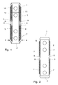
- eine Draufsicht auf einen erfindungsgemäßen Steckverbinder, der als U-Verbinder mit einer Bodenfläche und zwei an den Längsseitenkanten angeordneten Längsseitenstegen, ausgebildet ist,
- Fig. 2
- eine Ansicht der Bodenfläche desselben Verbinders,
- Fig. 3
- ein Schaubild des Verbinders.
- Fig. 1
- a plan view of a connector according to the invention, which is designed as a U-connector with a bottom surface and two arranged on the longitudinal side edges longitudinal side webs,
- Fig. 2
- a view of the bottom surface of the same connector,
- Fig. 3
- a diagram of the connector.
Mit 1 ist in
An den Außenseiten der Längsseitenstege 5 und 6 sind nach außen ragende, in Einsteckrichtung nach hinten weisende Lamellen 7 angeordnet, die sich elastisch verformen können und sich damit an das jeweilige Hohlprofil anzupassen vermögen. Die Lamellen 7 verkeilen sich an den Innenseiten des jeweiligen Hohlprofiles und verhindern so, daß der Steckverbinder aus dem Hohlprofil versehentlich herausgezogen wird.On the outer sides of the
Im Bereich der Mitte des Verbinders 1 sind ebenfalls an den Außenseiten der Längsseitenstege 5 und 6 für jede Einsteckrichtung jeweils ein Mittenanschlag 8 vorgesehen, der die Einstecktiefe des Verbinders 1 in die Hohlprofile begrenzt. Den Mittenanschlägen 8 ist jeweils ein Ausgleichselement 9 zugeordnet, das gegenüber den Mittenanschlägen 8 jeweils am anderen Längsseitensteg 5 und 6 vorgesehen ist.In the area of the center of the
Das Ausgleichselement 9 ist elastisch federn ausgebildet und sorgt einerseits dafür, daß die Hohlprofile gegen die Mittenanschläge 8 stoßen. Andererseits werden etwaige Fertigungstoleranzen des Hohlprofils ausgeglichen. Ein Wackeln des Verbinders 1 im Hohlprofil wird vermieden.The compensating
Die nach außen ragenden Lamellen 7 können sich über einen Teil oder die gesamte Höhe der Seitenstege 5 bzw. 6 erstrecken. Zudem können die Lamellen 7 von den Seitenstegen 5 bzw. 6 ausgehend sich verjüngend ausgebildet sein. Durch diese Dickenänderung in den Lamellen 7 wird eine selektive Anpassung der Elastizität der Lamellen 7 erzielt, die den Anpressdruck auch bei unterschiedlichen Größen der Hohlprofile, die durch Fertigungstoleranzen entstehen, weitgehend gleich halten. Es ist dabei auch denkbar, daß ein Steckverbinder 1 für zwei nebeneinander liegende Profilgrößen oder auch ähnliche Profilkonturen verwendbar ist und die Anpassung an die unterschiedlichen Hohlprofilabmessungen durch die elastischen Lamellen 7 vorgenommen wird.The outwardly projecting
Die Verjüngung der Lamellen 7 kann dabei schrittweise oder auch linear erfolgen. Diskontinuierliche Verjüngungsprofile sind ebenfalls denkbar.The taper of the
Zudem ist es denkbar, daß die Lamellen 7 auf wenigstens einem Teilbereich ihrer Höhe ein zusätzliches Stützelement 10 aufweisen, das an einer Lamelle 7 angeformt sein kann und dafür sorgt, daß diese Lamelle 7 und die benachbarte Lamelle 7 sich zum Beispiel ab einer vorbestimmten Biegung aneinander abzustützen vermögen. Dabei kann dieses Stützelement 10 auch so ausgeformt werden, daß die beiden Lamellen wenigstens über einen Teil ihrer Ausdehnung miteinander verbunden sind. Zusätzlich kann das Stützelement 10 auch als direkt an einer Lamelle 7 angeformtes Versteifungselement wirken, so daß die Lamelle 7 eine selektive Veränderung der Elastizität erfährt.In addition, it is conceivable that the
Die Lamellen 7 sind im abgebildeten Beispiel entgegen der Einsteckrichtung des Steckverbinders 1 ins Hohlprofil nach hinten geneigt. Besonders gute Ergebnisse in Bezug auf die aufzuwendende Einsteckkraft und die aufzuwendende Kraft um die Verbinder wieder aus dem Hohlprofil herauszuziehen wurden bei Neigungen zwischen 45 und 60° erzielt. Andere Neigungswinkel sind denkbar.The
Zudem ist es denkbar, daß die Lamellen 7 wenigstens annähernd lotrecht von den Längsseitenstegen 5 bzw. 6 abstehen und beim Einstecken in ein Hohlprofil umgebogen werden können.In addition, it is conceivable that the
Auch denkbar ist eine in Einsteckrichtung geneigte Ausgestaltung oder auch eine gebogene oder geschwungene Ausgestaltung.Also conceivable is an inclined in the insertion direction configuration or a curved or curved configuration.
Die Lamellen 7 sind elastisch ausgebildet und können jede für sich genommen relativ leicht umgeformt werden. Um einen hinreichenden Halt des Verbinders im Hohlprofil sicherzustellen ist eine Vielzahl von Lamellen 7 vorgesehen. Diese Lamellen 7 können dabei eine Dicke von unter einem Millimeter aufweisen. Die Lamellen 7 können auch dicht gepackt angeordnet werden. Der Abstand zwischen zwei benachbarten Lamellen 7 kann kleiner als deren Dicke sein.The
Die Lamellen 7 im dargestellten Beispiel reichen in Höhenrichtung nur über einen Teil der Höhe des Hohlprofiles.The
Die meisten Hohlprofile weisen im Bereich der Lamellen 7 eine sogenannte Butylsicke auf, in der beim Zusammensetzen einer Isolierglasscheibe Butyl eingebracht wird, das eine Klebung zwischen Abstandhalterhohlprofil und Scheibe herstellt.In the region of the
Viele Hohlprofile werden mit einem Trockenmittel gefüllt, um über einen langen Zeitraum zu gewährleisten, daß sich keine Feuchtigkeistniederschläge in den Isolierglasscheiben bilden.Many hollow profiles are filled with a desiccant to ensure over a long period of time that no moisture deposits are formed in the insulating glass panes.
Dieses Trockenmittel soll nicht bis zur Stoßkante der zu verbindenden Hohlprofilenden gelangen, da dort die Gefahr besteht, daß das Trockenmittel in den Scheibeninnenraum austritt und dort für Verunreinigungen sorgt, die unerwünscht sind.This desiccant should not get to the abutting edge of the hollow profile ends to be joined, since there is the danger that the desiccant exits into the disc interior and there provides impurities that are undesirable.
Um zu vermeiden, daß das Trockenmittel bis zu dieser Stoßstelle zu gelangen vermag können einzelne Lamellen 7 als Sperrlamellen 7a ausgebildet werden, die gegenüber den restlichen Lamellen 7 überhöht ausgebildet sind und eine Kontur aufweisen, die an die Innenkontur des Hohlprofiles angepasst ist. Die Sperrlamellen 7a können auch zusätzlich zu den Lamellen 7 vorgesehen werden. Um eine gute Absdichtung zu gewährleisten ist für jeden Seitensteg und für jede Einsteckrichtung mindestens eine Sperrlamelle 7a vorgesehen.In order to avoid that the desiccant can reach up to this joint can
Zusätzlich können zwischen den Seitenstegen 5 und 6 quer verlaufendeIn addition, between the side bars 5 and 6 transverse
Sperrlamellen 11 vorgesehen werden. Durch diese Sperrlamellen 11 wird ein Trockenmitteldurchlauf durch den Steckverbinder 1 unterbunden. Auch im Mittenbereich kann damit kein Trockenmittel mehr an die Stoßstelle der Hohlprofilenden gelangen.
Es hat sich dabei als sehr praktikabel erwiesen, wenn pro Einsteckrichtung des Steckverbinders wenigstens zwei Sperrlamellen 11 vorgesehen werden, da dann auch bei einem versehentlichen, geringfügigen Herausziehen des Steckverbinders 1 beim Handhaben von bereits fertiggestellten Abstandhalterrahmen ein unerwünschtes Austreten von Trockenmittel verhindert wird.It has proved to be very practical if at least two locking
Dieses unerwünschte geringfügige Herausziehen des Steckverbinders 1 tritt oftmals bei als Eck- oder Winkelverbinder ausgebildeten Steckverbindern 1 auf.This unwanted slight withdrawal of the
Die Seitenstege 5 und 6 tragen auf ihrer von der Bodenfläche 2 abgewandten Seite Halteeinrichtungen 12, die wenigstens annähernd lotrecht in Bezug auf die Bodenfläche ausgerichtet sind.The side bars 5 and 6 carry on their side facing away from the
Diese Halteeinrichtungen 12 weisen einen runden, ovalen oder auch eckigen Querschnitt auf und sind als diskrete Erhebungen ausgebildet. Die Halteeinrichtungen 12 können geringfügig entgegen der Einsteckrichtung nach hinten geneigt werden, wobei sich Neigungswinkel um 10° als sehr vorteilhaft erwiesen haben.These holding
Es ist auch denkbar, daß die Halteeinrichtungen 12 in Einsteckrichtung wenigstens geringfügig abgeschrägt sind.It is also conceivable that the holding
Die Halteeinrichtungen 12 sind ebenfalls selektiv elastisch ausgebildet und vermögen sich so an unterschiedliche Hohlprofilabmessungen anzupassen. Dabei wird durch die Form der Halteeinrichtungen 12, deren Abmessungen und deren Anzahl einerseits die Kraft beeinflusst, die aufgewendet werden muss, um den Steckverbinder 1 in das jeweilige Hohlprofil einsetzen zu können. Andererseits wird dadurch aber auch die Rückhaltekraft des Steckverbinders 1 im Hohlprofil gesteuert.The holding
Durch die elastische Ausgestaltung der Halteeinrichtungen 12 ist eine sehr gute Anpassung an unterschiedliche Hohlprofilabmessungen und unterschiedliche Hohlprofil-Formen sichergestellt. Toleranzen werden ausgeglichen, ohne die Rückhaltekraft des Steckverbinders negativ zu beeinflussen.Due to the elastic configuration of the holding
Über einen weiten Toleranzbereich wird immer eine wenigstens annähernd konstante Rückhaltekraft erzeugt.Over a wide tolerance range, an at least approximately constant retention force is always generated.
Zudem bleibt der Anpressdruck der Halteeinrichtungen 12 über diesen gesamten Bereich wenigstens annähernd konstant.In addition, the contact pressure of the holding
Wie auch bei den Lamellen 7 können die Halteeinrichtungen 12 sich verjüngend in linearer oder schrittweiser Form ausgebildet werden. Ebenso sind diskrete Versteifungselemente möglich.As with the
Die Enden des Steckverbinders 1 können abgeschrägt ausgebildet sein, um das Einstecken in die Hohlprofilenden zu erleichtern. Ein maschinelles Vorstecken oder auch Einstecken wird so unterstützt.The ends of the
Durch das Zusammenwirken aller vorgenannten Merkmale wird ein universell einsetzbarer Steckverbinder geschaffen, der als Gerad-, Winkel-, Kreuz- oder Eckverbinder einsetzbar ist. Die Einsatzmöglichkeiten sind ausschließlich von der Kombination der Einsteckschenkel anhängig.Due to the interaction of all the above features, a universally applicable connector is created, which can be used as a straight, angled, cross or corner connector. The possible applications are exclusively dependent on the combination of the Einsteckschenkel.
Zwischenstücke zwischen den beiden Einsteckschenkeln sind denkbar, die beispielsweise ein Eck oder einen Winkel ausformen und an den Querschnitt des jeweiligen Hohlprofiles angepasst sein können.Intermediate pieces between the two Einsteckschenkeln are conceivable, for example, form a corner or an angle and can be adapted to the cross section of the respective hollow profile.
Der erfindungsgemäße Steckverbinder kann bei allen Arten von Hohlprofilen eingesetzt werden. Denkbar ist der Einsatz bei Aluminium-, Stahl-, Edelstahl-, aber auch Kunststoff-Profilen.The connector according to the invention can be used in all types of hollow profiles. Conceivable is the use of aluminum, steel, stainless steel, but also plastic profiles.
Auch bei sehr weichen oder spröden Abstandhalterprofilen, die oftmals gerade bei Warm-Edge-Anwendungen zum Einsatz kommen, können erfindunsgemäße Steckverbinder 1 eingesetzt werden.Even with very soft or brittle spacer profiles, which are often used especially in warm-edge applications,
Die Steckverbinder 1 können aus Kunststoff, faserverstärktem Kunststoff, Aluminium, Metall oder Stahl gefertigt sein. Andere Materialien sind denkbar.The
Der Einsatz der Steckverbinder 1 ist bei allen Formaten von Isolierglasscheiben denkbar. Die Rückhaltekraft ist auch für große Schaufensterscheiben mit großenThe use of the
Abmessungen ausreichend. Auch bei der Herstellung solcher, oftmals mehrere Meter großer Scheiben werden die Abstandhalterhohlprofilenden sicher gehalten.Sufficient dimensions. Even in the production of such, often several meters large slices, the spacer hollow profile ends are held securely.
Claims (15)
Priority Applications (1)
| Application Number | Priority Date | Filing Date | Title |
|---|---|---|---|
| PL11160320T PL2374979T3 (en) | 2010-04-01 | 2011-03-29 | Plug-connector |
Applications Claiming Priority (1)
| Application Number | Priority Date | Filing Date | Title |
|---|---|---|---|
| DE102010016310A DE102010016310A1 (en) | 2010-04-01 | 2010-04-01 | Connectors |
Publications (3)
| Publication Number | Publication Date |
|---|---|
| EP2374979A2 true EP2374979A2 (en) | 2011-10-12 |
| EP2374979A3 EP2374979A3 (en) | 2011-10-19 |
| EP2374979B1 EP2374979B1 (en) | 2017-05-31 |
Family
ID=44148520
Family Applications (1)
| Application Number | Title | Priority Date | Filing Date |
|---|---|---|---|
| EP11160320.5A Active EP2374979B1 (en) | 2010-04-01 | 2011-03-29 | Plug-connector |
Country Status (6)
| Country | Link |
|---|---|
| US (1) | US20130029530A1 (en) |
| EP (1) | EP2374979B1 (en) |
| DE (1) | DE102010016310A1 (en) |
| DK (1) | DK2374979T3 (en) |
| PL (1) | PL2374979T3 (en) |
| WO (1) | WO2011128461A1 (en) |
Cited By (1)
| Publication number | Priority date | Publication date | Assignee | Title |
|---|---|---|---|---|
| EP2594722A1 (en) * | 2011-11-18 | 2013-05-22 | CERA Handelsgesellschaft mbH | Plug connector |
Families Citing this family (10)
| Publication number | Priority date | Publication date | Assignee | Title |
|---|---|---|---|---|
| DE102011055539A1 (en) * | 2011-11-18 | 2013-05-23 | Cera Handelsgesellschaft Mbh | Connector for connecting hollow profiles, particularly spacer hollow profiles of insulating glass panes, has base part and longitudinal bars upstanding from base part, where plug connector is formed as straight- or cross-connector |
| DE102012004043B4 (en) | 2012-03-02 | 2017-11-30 | Werner Schmitz | Insertion component, in particular plug-in connector for hollow profiles |
| DE102013103008A1 (en) | 2013-03-25 | 2014-09-25 | Cera Handelsgesellschaft Mbh | Connectors |
| DE102013105092A1 (en) | 2013-05-17 | 2014-11-20 | Werner Schmitz | Connector for connecting hollow profiles |
| DE102013114802A1 (en) | 2013-12-23 | 2015-06-25 | S & T Components Gmbh & Co. Kg | Corner joint bent wire |
| US10650037B2 (en) * | 2017-05-15 | 2020-05-12 | Sony Interactive Entertainment LLC | Enhancing information in a three-dimensional map |
| DE102018110130A1 (en) * | 2018-04-26 | 2019-10-31 | Werner Schmitz | Connector for hollow profiles |
| DE102021101371A1 (en) | 2021-01-22 | 2022-07-28 | Werner Schmitz | plug-in connector |
| DE102022112248A1 (en) | 2022-05-16 | 2023-11-16 | Werner Schmitz | Connectors |
| DE202022002823U1 (en) | 2022-05-16 | 2023-08-11 | Werner Schmitz | Connectors |
Family Cites Families (22)
| Publication number | Priority date | Publication date | Assignee | Title |
|---|---|---|---|---|
| BE1000350A5 (en) * | 1987-02-27 | 1988-11-08 | Saint Roch Glaceries | Hanger glass panel. |
| DE8805810U1 (en) * | 1987-05-02 | 1988-07-07 | Kronenberg, Max, 5650 Solingen | Corner brackets for connecting spacer hollow profiles |
| US5003741A (en) * | 1988-06-20 | 1991-04-02 | Yeh Kuo Huei | Structure of multi-function frame members |
| US4970840A (en) * | 1989-07-21 | 1990-11-20 | Raymond Ouellette | Window assembly and grille |
| DE9005886U1 (en) * | 1990-05-23 | 1990-07-26 | Cera Handelsgesellschaft Mbh, 8954 Biessenhofen | Plastic cross connectors for window bars of insulating glass panes consisting of hollow aluminium profile bars |
| US6764247B1 (en) * | 1997-09-11 | 2004-07-20 | Max Kronenberg | Plug-in connector for hollow sections |
| DE29918002U1 (en) * | 1999-10-12 | 2000-01-20 | CERA Handels GmbH, 87600 Kaufbeuren | Linear plastic connector for spacer profiles of multi-pane insulating glass |
| US6398449B1 (en) * | 1999-05-04 | 2002-06-04 | Cera Handelsgesellschaft Mbh | Linear connector of plastic material for joining spacing profiles of multiple insulating glasses |
| DE29913903U1 (en) * | 1999-08-10 | 1999-11-25 | CERA Handels GmbH, 87600 Kaufbeuren | Linear connector made of plastic for spacer profiles of multi-pane insulating glass |
| US6347902B1 (en) * | 1999-08-10 | 2002-02-19 | Cera Handelsgesellschaft Mbh | Linear connector of plastic material of joining spacing profiles of multiple insulating glasses |
| US6761008B2 (en) * | 1999-12-14 | 2004-07-13 | Mannington Mills, Inc. | Connecting system for surface coverings |
| DE20015913U1 (en) * | 2000-09-13 | 2002-02-07 | Kronenberg, Max, 42657 Solingen | Connectors for hollow profiles |
| DE20101486U1 (en) * | 2001-01-29 | 2002-06-13 | CERA Handelsgesellschaft mbH, 87600 Kaufbeuren | Plastic connector for connecting hollow spacer profiles and hollow rung profiles of a multi-pane insulating glass |
| DE102005045220B4 (en) * | 2004-10-20 | 2007-01-25 | Max Kronenberg | Hollow profile connectors |
| DE102005007230A1 (en) * | 2004-11-11 | 2006-09-14 | Schmitz, Werner, Dipl.-Ing. | Plug-in connector for sectional strips of spacer, has flaps flexibly linked to both sides of flat recess and filled with butyl cement that seals joint area at free end of strips, where recess is provided at side directed to sealing |
| DE102005027778B4 (en) * | 2005-03-22 | 2014-03-13 | Cera Handelsgesellschaft Mbh | U-shaped connector |
| MX2008001677A (en) * | 2005-08-01 | 2008-04-07 | Technoform Caprano Brunnhofer | Spacer arrangement with fusable connector for insulating glass units. |
| DE102006050644B4 (en) * | 2006-10-23 | 2008-10-16 | Ziegltrum & Wittmann Gmbh | Connecting piece and cross connector for window profiles |
| DE202007004924U1 (en) * | 2007-04-02 | 2008-08-14 | Kronenberg, Ralf Max | Connectors |
| US7908820B2 (en) * | 2007-10-29 | 2011-03-22 | Allmetal, Inc. | Spacer bar connector |
| DE202008013046U1 (en) * | 2008-10-02 | 2010-02-25 | Kronenberg, Max | Connectors |
| DE102009060151A1 (en) * | 2009-12-14 | 2011-06-16 | SaarGummi technologies S.à.r.l. | Butt joint between ends of sealing strands or a sealing strand |
-
2010
- 2010-04-01 DE DE102010016310A patent/DE102010016310A1/en not_active Withdrawn
-
2011
- 2011-03-29 PL PL11160320T patent/PL2374979T3/en unknown
- 2011-03-29 EP EP11160320.5A patent/EP2374979B1/en active Active
- 2011-03-29 DK DK11160320.5T patent/DK2374979T3/en active
- 2011-05-25 WO PCT/EP2011/058550 patent/WO2011128461A1/en active Application Filing
- 2011-05-25 US US13/638,154 patent/US20130029530A1/en not_active Abandoned
Non-Patent Citations (1)
| Title |
|---|
| None |
Cited By (1)
| Publication number | Priority date | Publication date | Assignee | Title |
|---|---|---|---|---|
| EP2594722A1 (en) * | 2011-11-18 | 2013-05-22 | CERA Handelsgesellschaft mbH | Plug connector |
Also Published As
| Publication number | Publication date |
|---|---|
| WO2011128461A4 (en) | 2012-01-05 |
| WO2011128461A1 (en) | 2011-10-20 |
| DE102010016310A1 (en) | 2011-10-06 |
| DK2374979T3 (en) | 2017-09-11 |
| WO2011128461A8 (en) | 2013-08-22 |
| US20130029530A1 (en) | 2013-01-31 |
| EP2374979A3 (en) | 2011-10-19 |
| PL2374979T3 (en) | 2017-10-31 |
| EP2374979B1 (en) | 2017-05-31 |
Similar Documents
| Publication | Publication Date | Title |
|---|---|---|
| EP2374979B1 (en) | Plug-connector | |
| WO2007118611A1 (en) | Glass-pane spacer corner connector | |
| EP2551438B1 (en) | Plug connector | |
| DE9207859U1 (en) | Glass pane holder | |
| DE102009003869A1 (en) | Longitudinal plug-in connector or U-shaped plug-in connector for spacer hollow profile for insulating glass plane, has base part and two brackets arranged in area of longitudinal side edges | |
| EP2933507A1 (en) | Butt joint structure, window/door frame or window/door wing frame and frame profile element | |
| EP1710387B1 (en) | Combination of U-shaped connector an hollow profile | |
| EP2045433B1 (en) | U-shaped connector | |
| EP2594722B1 (en) | Plug connector | |
| DE202007013996U1 (en) | U-shaped connector | |
| DE102014110549A1 (en) | Connectors | |
| EP2101029B1 (en) | Connector | |
| DE102012004043B4 (en) | Insertion component, in particular plug-in connector for hollow profiles | |
| EP2784261B1 (en) | Plug connector | |
| EP2472048B1 (en) | Connector | |
| DE102011055539A1 (en) | Connector for connecting hollow profiles, particularly spacer hollow profiles of insulating glass panes, has base part and longitudinal bars upstanding from base part, where plug connector is formed as straight- or cross-connector | |
| EP2631409B1 (en) | Plug connector | |
| DE2203237A1 (en) | COMPOSITE THERMAL INSULATING PROFILE FOR WINDOW FRAMES, DOOR FRAMES OR THE LIKE | |
| EP0110295A2 (en) | Spacer frame for edge-sealed insulating glazings | |
| EP3170963A1 (en) | Plug-connector | |
| DE102008048998B4 (en) | U-shaped connector with bridge | |
| EP1522669B1 (en) | Plastic straight connector for hollow frame section members in insulating glazing panels | |
| DE3822839A1 (en) | Connecting element for webs of laminated insulating glass | |
| DE102008023796A1 (en) | Connector for spacer profile strips between insulating glass panes | |
| EP3553267A1 (en) | Fitting |
Legal Events
| Date | Code | Title | Description |
|---|---|---|---|
| PUAI | Public reference made under article 153(3) epc to a published international application that has entered the european phase |
Free format text: ORIGINAL CODE: 0009012 |
|
| PUAL | Search report despatched |
Free format text: ORIGINAL CODE: 0009013 |
|
| AK | Designated contracting states |
Kind code of ref document: A2 Designated state(s): AL AT BE BG CH CY CZ DE DK EE ES FI FR GB GR HR HU IE IS IT LI LT LU LV MC MK MT NL NO PL PT RO RS SE SI SK SM TR |
|
| AX | Request for extension of the european patent |
Extension state: BA ME |
|
| AK | Designated contracting states |
Kind code of ref document: A3 Designated state(s): AL AT BE BG CH CY CZ DE DK EE ES FI FR GB GR HR HU IE IS IT LI LT LU LV MC MK MT NL NO PL PT RO RS SE SI SK SM TR |
|
| AX | Request for extension of the european patent |
Extension state: BA ME |
|
| RIC1 | Information provided on ipc code assigned before grant |
Ipc: E06B 3/667 20060101AFI20110914BHEP |
|
| 17P | Request for examination filed |
Effective date: 20111206 |
|
| 17Q | First examination report despatched |
Effective date: 20131203 |
|
| GRAP | Despatch of communication of intention to grant a patent |
Free format text: ORIGINAL CODE: EPIDOSNIGR1 |
|
| INTG | Intention to grant announced |
Effective date: 20170210 |
|
| GRAS | Grant fee paid |
Free format text: ORIGINAL CODE: EPIDOSNIGR3 |
|
| GRAA | (expected) grant |
Free format text: ORIGINAL CODE: 0009210 |
|
| AK | Designated contracting states |
Kind code of ref document: B1 Designated state(s): AL AT BE BG CH CY CZ DE DK EE ES FI FR GB GR HR HU IE IS IT LI LT LU LV MC MK MT NL NO PL PT RO RS SE SI SK SM TR |
|
| AX | Request for extension of the european patent |
Extension state: BA ME |
|
| REG | Reference to a national code |
Ref country code: CH Ref legal event code: EP Ref country code: GB Ref legal event code: FG4D Free format text: NOT ENGLISH |
|
| REG | Reference to a national code |
Ref country code: AT Ref legal event code: REF Ref document number: 897641 Country of ref document: AT Kind code of ref document: T Effective date: 20170615 |
|
| REG | Reference to a national code |
Ref country code: IE Ref legal event code: FG4D Free format text: LANGUAGE OF EP DOCUMENT: GERMAN |
|
| REG | Reference to a national code |
Ref country code: DE Ref legal event code: R096 Ref document number: 502011012336 Country of ref document: DE |
|
| REG | Reference to a national code |
Ref country code: CH Ref legal event code: NV Representative=s name: PA THOMAS HUTZELMANN, CH |
|
| REG | Reference to a national code |
Ref country code: DK Ref legal event code: T3 Effective date: 20170905 |
|
| REG | Reference to a national code |
Ref country code: NL Ref legal event code: MP Effective date: 20170531 |
|
| REG | Reference to a national code |
Ref country code: LT Ref legal event code: MG4D |
|
| RAP2 | Party data changed (patent owner data changed or rights of a patent transferred) |
Owner name: CERA GMBH |
|
| PG25 | Lapsed in a contracting state [announced via postgrant information from national office to epo] |
Ref country code: GR Free format text: LAPSE BECAUSE OF FAILURE TO SUBMIT A TRANSLATION OF THE DESCRIPTION OR TO PAY THE FEE WITHIN THE PRESCRIBED TIME-LIMIT Effective date: 20170901 Ref country code: FI Free format text: LAPSE BECAUSE OF FAILURE TO SUBMIT A TRANSLATION OF THE DESCRIPTION OR TO PAY THE FEE WITHIN THE PRESCRIBED TIME-LIMIT Effective date: 20170531 Ref country code: HR Free format text: LAPSE BECAUSE OF FAILURE TO SUBMIT A TRANSLATION OF THE DESCRIPTION OR TO PAY THE FEE WITHIN THE PRESCRIBED TIME-LIMIT Effective date: 20170531 Ref country code: NO Free format text: LAPSE BECAUSE OF FAILURE TO SUBMIT A TRANSLATION OF THE DESCRIPTION OR TO PAY THE FEE WITHIN THE PRESCRIBED TIME-LIMIT Effective date: 20170831 Ref country code: ES Free format text: LAPSE BECAUSE OF FAILURE TO SUBMIT A TRANSLATION OF THE DESCRIPTION OR TO PAY THE FEE WITHIN THE PRESCRIBED TIME-LIMIT Effective date: 20170531 Ref country code: LT Free format text: LAPSE BECAUSE OF FAILURE TO SUBMIT A TRANSLATION OF THE DESCRIPTION OR TO PAY THE FEE WITHIN THE PRESCRIBED TIME-LIMIT Effective date: 20170531 |
|
| PG25 | Lapsed in a contracting state [announced via postgrant information from national office to epo] |
Ref country code: LV Free format text: LAPSE BECAUSE OF FAILURE TO SUBMIT A TRANSLATION OF THE DESCRIPTION OR TO PAY THE FEE WITHIN THE PRESCRIBED TIME-LIMIT Effective date: 20170531 Ref country code: NL Free format text: LAPSE BECAUSE OF FAILURE TO SUBMIT A TRANSLATION OF THE DESCRIPTION OR TO PAY THE FEE WITHIN THE PRESCRIBED TIME-LIMIT Effective date: 20170531 Ref country code: BG Free format text: LAPSE BECAUSE OF FAILURE TO SUBMIT A TRANSLATION OF THE DESCRIPTION OR TO PAY THE FEE WITHIN THE PRESCRIBED TIME-LIMIT Effective date: 20170831 Ref country code: RS Free format text: LAPSE BECAUSE OF FAILURE TO SUBMIT A TRANSLATION OF THE DESCRIPTION OR TO PAY THE FEE WITHIN THE PRESCRIBED TIME-LIMIT Effective date: 20170531 Ref country code: SE Free format text: LAPSE BECAUSE OF FAILURE TO SUBMIT A TRANSLATION OF THE DESCRIPTION OR TO PAY THE FEE WITHIN THE PRESCRIBED TIME-LIMIT Effective date: 20170531 Ref country code: IS Free format text: LAPSE BECAUSE OF FAILURE TO SUBMIT A TRANSLATION OF THE DESCRIPTION OR TO PAY THE FEE WITHIN THE PRESCRIBED TIME-LIMIT Effective date: 20170930 |
|
| PG25 | Lapsed in a contracting state [announced via postgrant information from national office to epo] |
Ref country code: SK Free format text: LAPSE BECAUSE OF FAILURE TO SUBMIT A TRANSLATION OF THE DESCRIPTION OR TO PAY THE FEE WITHIN THE PRESCRIBED TIME-LIMIT Effective date: 20170531 Ref country code: RO Free format text: LAPSE BECAUSE OF FAILURE TO SUBMIT A TRANSLATION OF THE DESCRIPTION OR TO PAY THE FEE WITHIN THE PRESCRIBED TIME-LIMIT Effective date: 20170531 Ref country code: EE Free format text: LAPSE BECAUSE OF FAILURE TO SUBMIT A TRANSLATION OF THE DESCRIPTION OR TO PAY THE FEE WITHIN THE PRESCRIBED TIME-LIMIT Effective date: 20170531 |
|
| PG25 | Lapsed in a contracting state [announced via postgrant information from national office to epo] |
Ref country code: SM Free format text: LAPSE BECAUSE OF FAILURE TO SUBMIT A TRANSLATION OF THE DESCRIPTION OR TO PAY THE FEE WITHIN THE PRESCRIBED TIME-LIMIT Effective date: 20170531 |
|
| REG | Reference to a national code |
Ref country code: DE Ref legal event code: R097 Ref document number: 502011012336 Country of ref document: DE |
|
| PLBE | No opposition filed within time limit |
Free format text: ORIGINAL CODE: 0009261 |
|
| STAA | Information on the status of an ep patent application or granted ep patent |
Free format text: STATUS: NO OPPOSITION FILED WITHIN TIME LIMIT |
|
| PGFP | Annual fee paid to national office [announced via postgrant information from national office to epo] |
Ref country code: CZ Payment date: 20180327 Year of fee payment: 8 |
|
| 26N | No opposition filed |
Effective date: 20180301 |
|
| PG25 | Lapsed in a contracting state [announced via postgrant information from national office to epo] |
Ref country code: SI Free format text: LAPSE BECAUSE OF FAILURE TO SUBMIT A TRANSLATION OF THE DESCRIPTION OR TO PAY THE FEE WITHIN THE PRESCRIBED TIME-LIMIT Effective date: 20170531 |
|
| PGFP | Annual fee paid to national office [announced via postgrant information from national office to epo] |
Ref country code: DE Payment date: 20180426 Year of fee payment: 8 |
|
| PG25 | Lapsed in a contracting state [announced via postgrant information from national office to epo] |
Ref country code: MT Free format text: LAPSE BECAUSE OF FAILURE TO SUBMIT A TRANSLATION OF THE DESCRIPTION OR TO PAY THE FEE WITHIN THE PRESCRIBED TIME-LIMIT Effective date: 20170531 |
|
| REG | Reference to a national code |
Ref country code: DK Ref legal event code: EBP Effective date: 20180331 |
|
| PGFP | Annual fee paid to national office [announced via postgrant information from national office to epo] |
Ref country code: GB Payment date: 20180430 Year of fee payment: 8 |
|
| REG | Reference to a national code |
Ref country code: CH Ref legal event code: PL |
|
| PG25 | Lapsed in a contracting state [announced via postgrant information from national office to epo] |
Ref country code: MC Free format text: LAPSE BECAUSE OF FAILURE TO SUBMIT A TRANSLATION OF THE DESCRIPTION OR TO PAY THE FEE WITHIN THE PRESCRIBED TIME-LIMIT Effective date: 20170531 |
|
| REG | Reference to a national code |
Ref country code: BE Ref legal event code: MM Effective date: 20180331 |
|
| REG | Reference to a national code |
Ref country code: IE Ref legal event code: MM4A |
|
| PG25 | Lapsed in a contracting state [announced via postgrant information from national office to epo] |
Ref country code: LU Free format text: LAPSE BECAUSE OF NON-PAYMENT OF DUE FEES Effective date: 20180329 |
|
| PG25 | Lapsed in a contracting state [announced via postgrant information from national office to epo] |
Ref country code: IE Free format text: LAPSE BECAUSE OF NON-PAYMENT OF DUE FEES Effective date: 20180329 |
|
| PG25 | Lapsed in a contracting state [announced via postgrant information from national office to epo] |
Ref country code: BE Free format text: LAPSE BECAUSE OF NON-PAYMENT OF DUE FEES Effective date: 20180331 Ref country code: LI Free format text: LAPSE BECAUSE OF NON-PAYMENT OF DUE FEES Effective date: 20180331 Ref country code: IT Free format text: LAPSE BECAUSE OF NON-PAYMENT OF DUE FEES Effective date: 20180329 Ref country code: CH Free format text: LAPSE BECAUSE OF NON-PAYMENT OF DUE FEES Effective date: 20180331 |
|
| PG25 | Lapsed in a contracting state [announced via postgrant information from national office to epo] |
Ref country code: FR Free format text: LAPSE BECAUSE OF NON-PAYMENT OF DUE FEES Effective date: 20180331 |
|
| REG | Reference to a national code |
Ref country code: AT Ref legal event code: MM01 Ref document number: 897641 Country of ref document: AT Kind code of ref document: T Effective date: 20180329 |
|
| PG25 | Lapsed in a contracting state [announced via postgrant information from national office to epo] |
Ref country code: DK Free format text: LAPSE BECAUSE OF NON-PAYMENT OF DUE FEES Effective date: 20180331 |
|
| REG | Reference to a national code |
Ref country code: DE Ref legal event code: R119 Ref document number: 502011012336 Country of ref document: DE |
|
| PG25 | Lapsed in a contracting state [announced via postgrant information from national office to epo] |
Ref country code: CZ Free format text: LAPSE BECAUSE OF NON-PAYMENT OF DUE FEES Effective date: 20190329 Ref country code: AT Free format text: LAPSE BECAUSE OF NON-PAYMENT OF DUE FEES Effective date: 20180329 |
|
| GBPC | Gb: european patent ceased through non-payment of renewal fee |
Effective date: 20190329 |
|
| PG25 | Lapsed in a contracting state [announced via postgrant information from national office to epo] |
Ref country code: PL Free format text: LAPSE BECAUSE OF NON-PAYMENT OF DUE FEES Effective date: 20180329 |
|
| PG25 | Lapsed in a contracting state [announced via postgrant information from national office to epo] |
Ref country code: DE Free format text: LAPSE BECAUSE OF NON-PAYMENT OF DUE FEES Effective date: 20191001 Ref country code: GB Free format text: LAPSE BECAUSE OF NON-PAYMENT OF DUE FEES Effective date: 20190329 |
|
| PG25 | Lapsed in a contracting state [announced via postgrant information from national office to epo] |
Ref country code: TR Free format text: LAPSE BECAUSE OF FAILURE TO SUBMIT A TRANSLATION OF THE DESCRIPTION OR TO PAY THE FEE WITHIN THE PRESCRIBED TIME-LIMIT Effective date: 20170531 |
|
| PG25 | Lapsed in a contracting state [announced via postgrant information from national office to epo] |
Ref country code: PT Free format text: LAPSE BECAUSE OF FAILURE TO SUBMIT A TRANSLATION OF THE DESCRIPTION OR TO PAY THE FEE WITHIN THE PRESCRIBED TIME-LIMIT Effective date: 20170531 Ref country code: HU Free format text: LAPSE BECAUSE OF FAILURE TO SUBMIT A TRANSLATION OF THE DESCRIPTION OR TO PAY THE FEE WITHIN THE PRESCRIBED TIME-LIMIT; INVALID AB INITIO Effective date: 20110329 |
|
| PG25 | Lapsed in a contracting state [announced via postgrant information from national office to epo] |
Ref country code: MK Free format text: LAPSE BECAUSE OF NON-PAYMENT OF DUE FEES Effective date: 20170531 Ref country code: CY Free format text: LAPSE BECAUSE OF FAILURE TO SUBMIT A TRANSLATION OF THE DESCRIPTION OR TO PAY THE FEE WITHIN THE PRESCRIBED TIME-LIMIT Effective date: 20170531 |
|
| PG25 | Lapsed in a contracting state [announced via postgrant information from national office to epo] |
Ref country code: AL Free format text: LAPSE BECAUSE OF FAILURE TO SUBMIT A TRANSLATION OF THE DESCRIPTION OR TO PAY THE FEE WITHIN THE PRESCRIBED TIME-LIMIT Effective date: 20170531 |