EP2374938A1 - Inflatable actuator for a dock leveler deck - Google Patents
Inflatable actuator for a dock leveler deck Download PDFInfo
- Publication number
- EP2374938A1 EP2374938A1 EP11004599A EP11004599A EP2374938A1 EP 2374938 A1 EP2374938 A1 EP 2374938A1 EP 11004599 A EP11004599 A EP 11004599A EP 11004599 A EP11004599 A EP 11004599A EP 2374938 A1 EP2374938 A1 EP 2374938A1
- Authority
- EP
- European Patent Office
- Prior art keywords
- actuator
- blower
- deck
- dock leveler
- inflatable actuator
- Prior art date
- Legal status (The legal status is an assumption and is not a legal conclusion. Google has not performed a legal analysis and makes no representation as to the accuracy of the status listed.)
- Granted
Links
- 239000012530 fluid Substances 0.000 claims description 6
- 238000010586 diagram Methods 0.000 description 6
- 239000004677 Nylon Substances 0.000 description 2
- XECAHXYUAAWDEL-UHFFFAOYSA-N acrylonitrile butadiene styrene Chemical compound C=CC=C.C=CC#N.C=CC1=CC=CC=C1 XECAHXYUAAWDEL-UHFFFAOYSA-N 0.000 description 2
- 239000004676 acrylonitrile butadiene styrene Substances 0.000 description 2
- 229920000122 acrylonitrile butadiene styrene Polymers 0.000 description 2
- 239000004744 fabric Substances 0.000 description 2
- 239000000463 material Substances 0.000 description 2
- 229920001778 nylon Polymers 0.000 description 2
- 238000007789 sealing Methods 0.000 description 2
- 230000009172 bursting Effects 0.000 description 1
- 238000004140 cleaning Methods 0.000 description 1
- 238000009833 condensation Methods 0.000 description 1
- 230000005494 condensation Effects 0.000 description 1
- 230000001419 dependent effect Effects 0.000 description 1
- 230000008595 infiltration Effects 0.000 description 1
- 238000001764 infiltration Methods 0.000 description 1
- 238000012986 modification Methods 0.000 description 1
- 230000004048 modification Effects 0.000 description 1
- 230000000284 resting effect Effects 0.000 description 1
Images






Classifications
-
- B—PERFORMING OPERATIONS; TRANSPORTING
- B65—CONVEYING; PACKING; STORING; HANDLING THIN OR FILAMENTARY MATERIAL
- B65G—TRANSPORT OR STORAGE DEVICES, e.g. CONVEYORS FOR LOADING OR TIPPING, SHOP CONVEYOR SYSTEMS OR PNEUMATIC TUBE CONVEYORS
- B65G69/00—Auxiliary measures taken, or devices used, in connection with loading or unloading
- B65G69/28—Loading ramps; Loading docks
- B65G69/2805—Loading ramps; Loading docks permanently installed on the dock
- B65G69/2811—Loading ramps; Loading docks permanently installed on the dock pivoting ramps
- B65G69/2817—Loading ramps; Loading docks permanently installed on the dock pivoting ramps with fluid-operated means
Definitions
- the subject invention generally relates to dock levelers, and more specifically to a dock leveler whose deck is raised by an inflatable member.
- Loading docks often include a dock leveler to facilitate the loading or unloading of a truck's cargo.
- the dock leveler provides a bridge that material handling equipment and personnel can use to travel between a loading dock platform and the bed of the truck.
- Dock levelers usually include a deck or ramp that can pivot about its rear edge to raise or lower its front edge.
- a lip plate extends from the front edge of the deck and is adapted to engage the rear of the truck bed.
- the lip plate is usually movable between a stored, retracted position and an extended, vehicle-engaging position. The pivotal movement of the deck enables the dock leveler to set the lip plate on or remove it from the truck bed.
- a dock leveler To pivot a deck, a dock leveler usually includes some type of actuator that extends, expands or otherwise moves to force the deck upward. Downward movement of the deck may be achieved by relying on the weight of the deck (biased down dock leveler) or by physically pushing the deck back down with an external force or weight (biased up dock leveler), such as the weight of a person standing on the deck.
- the subject invention pertains to inflatable actuators, which comprise an inflatable chamber disposed underneath a deck.
- a blower discharges pressurized air into the chamber, which causes the chamber to expand and lift the deck.
- the weight of the deck forces the air within the chamber to backflow through the blower, whereby the chamber controllably collapses to lower the deck.
- US 2003/0204921 discloses an air operated dock leveler for use at a loading dock, according to the preamble of claim 1.
- inflatable actuators are effective at raising a deck, the blowers of such actuators can be particularly loud. Moreover, a pit in which a dock leveler is installed can become quite dirty from the traffic across the deck and by debris infiltration from the adjacent driveway. An inflatable chamber, its blower and various other dock leveler components underneath the deck can be difficult to clean due to the limited space of a typical dock leveler pit. Consequently, a need exists for an inflatable actuator that is quieter and easier to clean and whose blower is protected from debris.
- the invention provides an air operated dock leveler for use at a loading dock, according to the subject-matter of independent claim 1. Further aspects and embodiments of the invention are set forth in the dependent claims, the following description and the drawings.
- an inflatable actuator for a dock leveler has an internal volume of air contained between a pliable upper section a more rigid base.
- the inflatable actuator is substantially cylindrical.
- the more rigid base includes an upwardly extending flange joined to which the pliable upper section is joined.
- the inlet and/or outlet of the blower passes through the more rigid base to maintain the integrity of the pliable upper section.
- the blower is mounted to the base of inflatable actuator.
- the inflatable actuator includes an access opening.
- an inflatable actuator includes a valve system that enables a blower to selective inflate or forcibly deflate the actuator.
- a blower can forcibly collapse an inflatable actuator while the dock leveler deck remains elevated and substantially stationary.
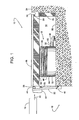
- Figure 1 is a side view of a dock leveler whose deck, shown in a cross-traffic position, can be raised by an inflatable actuator.
- Figure 2 is a cross-sectional side view similar to Figure 1 but with the actuator inflated to lift the deck.
- Figure 3 is similar to Figure 1 but with the actuator deflated and the lip of the dock leveler resting upon the rear of a truck bed.
- Figure 4 is similar to Figure 2 but showing another embodiment where the blower is inside the actuator.
- Figure 5 is similar to Figure 4 but showing the blower installed at another location inside the actuator.
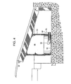
- Figure 6 is similar to Figures 4 and 5 but showing an inflatable actuator with various access openings that are covered or otherwise closed.
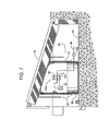
- Figure 7 is cross-sectional side view showing an inflated actuator with an internal blower and valve system, wherein the valve system is schematically illustrated.
- Figure 8 is a side view of the actuator of Figure 7 but with a portion cut away to show the inside of the actuator when forcible deflated up against the underside of the deck.
- Figure 9a is a schematic diagram showing one embodiment of an inflated actuator, a valve system in an inflate configuration, and a blower.
- Figure 9b is a schematic diagram similar to Figure 9a but showing the valve system in a deflate configuration, wherein the blower forcibly deflates the actuator.
- Figure 10a is a schematic diagram showing a second embodiment of an inflated actuator, a valve system in an inflate configuration, and a blower.
- Figure 10b is a schematic diagram similar to Figure 10a but showing the valve system in a deflate configuration, wherein the blower forcibly deflates the actuator.
- Figure 11 a is a schematic diagram showing a second embodiment of an inflated actuator, valve system in an inflate configuration, and a blower.
- Figure 11b is a schematic diagram similar to Figure 11a but showing the valve system in a deflate configuration, wherein the blower forcibly deflates the actuator.
- FIGS 1 - 3 show various operating positions of a dock leveler 10 and its inflatable actuator 12 which are installed within a pit 14 of a loading dock 16.
- dock leveler 10 includes a pivotal deck 18 and a lip 22 that provide a path for personnel and material handling equipment to travel between a platform 24 of the dock and vehicle 19.
- inflatable actuator 12 can pivot deck 18 about a hinge 28 that couples a rear edge 30 of the deck to a supporting frame 32. This enables dock leveler 10 to set lip 22 on or remove it from the truck bed.
- Lip 22 extends from deck 18 to bridge the gap between front edge 26 and a rear edge 34 of vehicle 19.
- blower 36 or some other source of pressurized air forces air through an inlet 38 to expand inflatable actuator 12.
- blower 36 is de-energized, which allows the deck's weight to controllably collapse actuator 12 by forcing air to backflow through blower 36.
- the sequence of operation at dock 16 typically begins with dock leveler 10 at its stored, cross-traffic position of in Figure 1 .
- inflatable actuator 12 is deflated
- lip 22 is at its pendant position supported by a set of lip keepers 40
- the top surface of deck 18 is generally flush with platform 24.
- Arrow 42 represents vehicle 19 backing the rear edge of its truck bed toward a bumper 44 of dock 16.
- blower 36 is energized to inflate actuator 12 with relatively low-pressure air (preferably less than 10 psig.).
- relatively low-pressure air preferably less than 10 psig.
- a centrifugal blower is just one example of such a source of low-pressure air.
- inflatable actuator 12 expands, it forces deck 18 upward.
- Arrow 48 schematically represents any actuator capable of moving lip 22 (e.g., by acting upon a lug 50 extending from lip 22).
- Examples of such a lip actuator include, but are not limited to, pneumatic cylinders, low-pressure air actuator, coil springs, high-pressure air springs, linear motors, mechanical linkages responsive to the movement of deck 18, and various combinations thereof.
- actuator 12 comprises a pliable upper section 52, such as a nylon fabric tube, bladder, bag, or the like.
- An upper panel 54 of section 52 seals the upper end of actuator 12.
- upper section 52 can be bonded, fused, welded, or otherwise attached to a more rigid base 56.
- the side portion of pliable upper section 52, upper panel 54, and base 56 define an expandable chamber that contains an internal volume of air 58.
- a tube 60 places inlet 38 of actuator 12 in fluid communication with a discharge outlet 62 of blower 36, so blower 36 can force air into the chamber to expand actuator 12.
- blower 36 When blower 36 is de-energized, the weight of deck 18 can force the air out of the chamber in reverse flow through blower 36, as deck 18 descends.
- actuator 12 may vary, in some embodiments, pliable upper section 52 is made of a nylon fabric and base 56 is made of ABS (Acrylonitrile Butadiene Styrene). Actuator 12 is generally cylindrical when inflated. In some cases, base 56 includes an upwardly extending flange 64 that adds rigidity to base 56 and provides a generally strong, stationary wall through which tube 60 can extend. The rigidity of base 56 and joining the base in direct sealing relationship to upper section 52 at a circumferential joint 66 may provide several benefits. First, a rigid base may be less likely to bulge under pressure, thus actuator 12 maintains a generally constant area of contact between the bottom of actuator 12 and a floor 68 of pit 14.
- a rigid base may be more durable and less likely to be punctured by debris on pit floor 68.
- a smooth, rigid base may be easier to clean.
- having upper section 52 sealingly joined to base 56 at joint 66 eliminates the need for an additional internal sealing member just to seal off the bottom of actuator 12.
- blower 36 may be installed somewhere inside the inflatable actuator to provide quieter operation and help keep the blower clean.
- blower 36 is mounted to base 56, and an inlet tube 70 extending from the suction opening of blower 36 and passing through flange 64 or through upper section 52 places the internal volume of air 58 in fluid communication with the exterior air.
- a suitable air filter can be connected in series with tube 70 and installed outside of the inflatable actuator so that the filter can be readily serviced.
- an upper section 72 of an inflatable actuator 74 supports blower 36.
- Tube 76 e.g., a flexible hose
- Tube 76 extending from the suction opening of blower 36 and passing through an upper panel 78 of upper section 72 places the internal volume of air in fluid communication with the exterior air.
- tube 76 is shown extending thorough upper panel 78, alternatively tube 76 could also be routed through upper section 72, a base 75 or any other part of inflatable actuator 74.
- base 75 is shown to include a drain plug 81 for draining condensation 87 or any other fluid that may happen to collect at the bottom of base 75.
- Base 75 may also include a raised central portion 83 that creates a trough 85 for collecting the fluid and directing it toward drain plug 81.
- Bases 56, 64 and 86 can be modified to also include such a drain plug and trough.
- an inflatable actuator 80 may include an access opening, which may be selectively closed by some appropriate device, such as a zipper 82 or a removable cover 84.
- Zipper 82 is preferably installed horizontally as shown because the bursting stress in an upper section 85 is greater in the circumferential direction than vertically, thus a horizontal zipper is less likely to pull apart.
- a horizontal zipper avoids being creased at multiple locations when upper section 85 folds as actuator 80 collapses.
- actuator 88 first lifts deck 18 to the position of Figure 7 , and a prop 90 is installed to keep it there. Once prop 90 supports the weight of deck 18, blower 36 in conjunction with a valve system evacuates the air from within actuator 88, whereby the reduced air pressure inside actuator 88 draws base 86 up to its position of Figure 8 because the top of actuator 88 is secured to the underside of deck 18.
- a retainer system 92 such as a chain, hook, latch, strap, cable, or the like can hold the base 86 in its raised position even after blower 36 is de-energized.
- valve system 94a, 94b, or 94c determines whether blower 36 inflates or deflates actuator 88.
- Valve system 94a for example, includes a 2-position, 4-way valve 96 that could be actuated electrically, manually, or otherwise.
- Valve 96 in the position shown in Figures 7 and 9a allows blower 36 to draw in exterior air through a first line 98 and discharge the air through a second line 100 into actuator 88, thereby pressurizing actuator 88 to raise deck 18.
- a filter 102 can be added to help keep the interior of actuator 88, valve 96, and blower 36 clean.
- valve 96 can be positioned as shown in Figures 8 and 9b , whereby valve 96 allows blower 36 to evacuate air from within actuator 88 via line 100 and discharge the air through line 98.
- valve system 94a blower 36 and filter 102 can be installed inside actuator 88 as shown in Figures 7 and 8 , or valve system 94a can be installed outside of actuator 88 as shown in Figures 9a and 9b (also similar to Figures 1 - 3 ).
- valve systems 94b and 94c which are alternatives to valve system 94a.
- Valve system 94b of Figures 10a and 10b includes two 2-position, 3-way valves 104 and 106 that can be actuated electrically, manually, or otherwise.
- Valves 104 and 106 in their positions shown in Figure 10a allow blower 36 to draw in exterior air through a first line 108 and discharge the air through a second line 110 into actuator 88, thereby pressurizing actuator 88 to raise deck 18.
- valves 104 and 106 can be positioned as shown in Figure 10b , whereby valves 104 and 106 allow blower 36 to evacuate air from within actuator 88 via line 110 and discharge the air through a discharge line 112.
- a valve system 94c of Figures 11 and 11b includes four 2-position, 2-way valves 114 that can be actuated electrically, manually, or otherwise. Valves 114 in their positions shown in Figure 11 a allow blower 36 to draw in exterior air through a first line 116 and discharge the air through a second line 118 into actuator 88, thereby pressurizing actuator 88 to raise deck 18. To lift base 86, valves 114 can be positioned as shown in Figure 11b , whereby the valves allow blower 36 to evacuate air from within actuator 88 via line 118 and discharge the air through a discharge line 120.
Landscapes
- Engineering & Computer Science (AREA)
- Mechanical Engineering (AREA)
- Types And Forms Of Lifts (AREA)
- Fluid-Pressure Circuits (AREA)
- Actuator (AREA)
- Body Structure For Vehicles (AREA)
- Vehicle Cleaning, Maintenance, Repair, Refitting, And Outriggers (AREA)
- Motorcycle And Bicycle Frame (AREA)
- Forklifts And Lifting Vehicles (AREA)
Abstract
Description
- The subject invention generally relates to dock levelers, and more specifically to a dock leveler whose deck is raised by an inflatable member.
- Loading docks often include a dock leveler to facilitate the loading or unloading of a truck's cargo. The dock leveler provides a bridge that material handling equipment and personnel can use to travel between a loading dock platform and the bed of the truck. Dock levelers usually include a deck or ramp that can pivot about its rear edge to raise or lower its front edge. Often a lip plate extends from the front edge of the deck and is adapted to engage the rear of the truck bed. The lip plate is usually movable between a stored, retracted position and an extended, vehicle-engaging position. The pivotal movement of the deck enables the dock leveler to set the lip plate on or remove it from the truck bed.
- To pivot a deck, a dock leveler usually includes some type of actuator that extends, expands or otherwise moves to force the deck upward. Downward movement of the deck may be achieved by relying on the weight of the deck (biased down dock leveler) or by physically pushing the deck back down with an external force or weight (biased up dock leveler), such as the weight of a person standing on the deck.
- There are a wide variety of well-known actuators available today. Some common ones include, hydraulic cylinders, pneumatic cylinders, coil springs, high-pressure air springs, linear motors, and inflatable actuators. The subject invention pertains to inflatable actuators, which comprise an inflatable chamber disposed underneath a deck. To raise the deck, a blower discharges pressurized air into the chamber, which causes the chamber to expand and lift the deck. Upon de-energizing the blower, the weight of the deck forces the air within the chamber to backflow through the blower, whereby the chamber controllably collapses to lower the deck.
US 2003/0204921 discloses an air operated dock leveler for use at a loading dock, according to the preamble of claim 1.
Although inflatable actuators are effective at raising a deck, the blowers of such actuators can be particularly loud. Moreover, a pit in which a dock leveler is installed can become quite dirty from the traffic across the deck and by debris infiltration from the adjacent driveway. An inflatable chamber, its blower and various other dock leveler components underneath the deck can be difficult to clean due to the limited space of a typical dock leveler pit.
Consequently, a need exists for an inflatable actuator that is quieter and easier to clean and whose blower is protected from debris. - According to a first aspect, the invention provides an air operated dock leveler for use at a loading dock, according to the subject-matter of independent claim 1. Further aspects and embodiments of the invention are set forth in the dependent claims, the following description and the drawings.
- In some embodiments, an inflatable actuator for a dock leveler has an internal volume of air contained between a pliable upper section a more rigid base.
- In some embodiments, the inflatable actuator is substantially cylindrical.
- In some embodiments, the more rigid base includes an upwardly extending flange joined to which the pliable upper section is joined.
- In some embodiments, the inlet and/or outlet of the blower passes through the more rigid base to maintain the integrity of the pliable upper section.
- In some embodiments, the blower is mounted to the base of inflatable actuator.
- In some embodiments, the inflatable actuator includes an access opening.
- In some embodiments, an inflatable actuator includes a valve system that enables a blower to selective inflate or forcibly deflate the actuator.
- In some embodiments, a blower can forcibly collapse an inflatable actuator while the dock leveler deck remains elevated and substantially stationary.
-
Figure 1 is a side view of a dock leveler whose deck, shown in a cross-traffic position, can be raised by an inflatable actuator. -
Figure 2 is a cross-sectional side view similar toFigure 1 but with the actuator inflated to lift the deck. -
Figure 3 is similar toFigure 1 but with the actuator deflated and the lip of the dock leveler resting upon the rear of a truck bed. -
Figure 4 is similar toFigure 2 but showing another embodiment where the blower is inside the actuator. -
Figure 5 is similar toFigure 4 but showing the blower installed at another location inside the actuator. -
Figure 6 is similar toFigures 4 and5 but showing an inflatable actuator with various access openings that are covered or otherwise closed. -
Figure 7 is cross-sectional side view showing an inflated actuator with an internal blower and valve system, wherein the valve system is schematically illustrated. -
Figure 8 is a side view of the actuator ofFigure 7 but with a portion cut away to show the inside of the actuator when forcible deflated up against the underside of the deck. -
Figure 9a is a schematic diagram showing one embodiment of an inflated actuator, a valve system in an inflate configuration, and a blower. -
Figure 9b is a schematic diagram similar toFigure 9a but showing the valve system in a deflate configuration, wherein the blower forcibly deflates the actuator. -
Figure 10a is a schematic diagram showing a second embodiment of an inflated actuator, a valve system in an inflate configuration, and a blower. -
Figure 10b is a schematic diagram similar toFigure 10a but showing the valve system in a deflate configuration, wherein the blower forcibly deflates the actuator. -
Figure 11 a is a schematic diagram showing a second embodiment of an inflated actuator, valve system in an inflate configuration, and a blower. -
Figure 11b is a schematic diagram similar toFigure 11a but showing the valve system in a deflate configuration, wherein the blower forcibly deflates the actuator. -
Figures 1 - 3 show various operating positions of adock leveler 10 and itsinflatable actuator 12 which are installed within apit 14 of aloading dock 16. To facilitate loading or unloading cargo from a vehicle 19 (e.g., truck trailer, etc.),dock leveler 10 includes apivotal deck 18 and alip 22 that provide a path for personnel and material handling equipment to travel between aplatform 24 of the dock andvehicle 19. To selectively raise and lower afront edge 26 of the deck,inflatable actuator 12 can pivotdeck 18 about ahinge 28 that couples arear edge 30 of the deck to a supportingframe 32. This enablesdock leveler 10 to setlip 22 on or remove it from the truck bed.Lip 22 extends fromdeck 18 to bridge the gap betweenfront edge 26 and arear edge 34 ofvehicle 19. - To raise
deck 18, ablower 36 or some other source of pressurized air forces air through aninlet 38 to expandinflatable actuator 12. Tolower deck 18,blower 36 is de-energized, which allows the deck's weight to controllably collapseactuator 12 by forcing air to backflow throughblower 36. - The sequence of operation at
dock 16 typically begins withdock leveler 10 at its stored, cross-traffic position of inFigure 1 . In this position,inflatable actuator 12 is deflated,lip 22 is at its pendant position supported by a set oflip keepers 40, and the top surface ofdeck 18 is generally flush withplatform 24. Arrow 42 representsvehicle 19 backing the rear edge of its truck bed toward abumper 44 ofdock 16. - Next, in
Figure 2 ,blower 36 is energized to inflateactuator 12 with relatively low-pressure air (preferably less than 10 psig.). A centrifugal blower is just one example of such a source of low-pressure air. Asinflatable actuator 12 expands, it forcesdeck 18 upward.Lip 22, which a hinge 46 pivotally couples to the deck'sfront edge 26, pivots outward to extend out over the truck bed ofvehicle 19.Arrow 48 schematically represents any actuator capable of moving lip 22 (e.g., by acting upon alug 50 extending from lip 22). Examples of such a lip actuator include, but are not limited to, pneumatic cylinders, low-pressure air actuator, coil springs, high-pressure air springs, linear motors, mechanical linkages responsive to the movement ofdeck 18, and various combinations thereof. - After
lip 22 extends out overrear edge 34 ofvehicle 19, it is selectively locked or otherwise held in this position andblower 36 is de-energized to deflateactuator 12. This allowsdeck 18 to descend tolower lip 22 upon the truck bed ofvehicle 19, as shown inFigure 3 . In this position, cargo can be readily added or removed fromvehicle 19. - To enable
inflatable actuator 12 to raise andlower deck 18 in such a manner,actuator 12 comprises a pliableupper section 52, such as a nylon fabric tube, bladder, bag, or the like. Anupper panel 54 ofsection 52 seals the upper end ofactuator 12. To seal a lower end of the actuator,upper section 52 can be bonded, fused, welded, or otherwise attached to a morerigid base 56. Together, the side portion of pliableupper section 52,upper panel 54, andbase 56 define an expandable chamber that contains an internal volume ofair 58. Atube 60places inlet 38 ofactuator 12 in fluid communication with adischarge outlet 62 ofblower 36, soblower 36 can force air into the chamber to expandactuator 12. Whenblower 36 is de-energized, the weight ofdeck 18 can force the air out of the chamber in reverse flow throughblower 36, asdeck 18 descends. - Although the structural details of
actuator 12 may vary, in some embodiments, pliableupper section 52 is made of a nylon fabric andbase 56 is made of ABS (Acrylonitrile Butadiene Styrene).Actuator 12 is generally cylindrical when inflated. In some cases,base 56 includes an upwardly extendingflange 64 that adds rigidity tobase 56 and provides a generally strong, stationary wall through whichtube 60 can extend. The rigidity ofbase 56 and joining the base in direct sealing relationship toupper section 52 at a circumferential joint 66 may provide several benefits. First, a rigid base may be less likely to bulge under pressure, thus actuator 12 maintains a generally constant area of contact between the bottom ofactuator 12 and afloor 68 ofpit 14. With a constant area of contact, debris in the pit is less likely to work itself underneathactuator 12. Second, a rigid base may be more durable and less likely to be punctured by debris onpit floor 68. Third, a smooth, rigid base may be easier to clean. Fourth, havingupper section 52 sealingly joined to base 56 at joint 66 eliminates the need for an additional internal sealing member just to seal off the bottom ofactuator 12. - Referring to
Figures 4 and5 , in somecases blower 36 may be installed somewhere inside the inflatable actuator to provide quieter operation and help keep the blower clean. InFigure 4 , for example,blower 36 is mounted tobase 56, and aninlet tube 70 extending from the suction opening ofblower 36 and passing throughflange 64 or throughupper section 52 places the internal volume ofair 58 in fluid communication with the exterior air. A suitable air filter can be connected in series withtube 70 and installed outside of the inflatable actuator so that the filter can be readily serviced. - In
Figure 5 , anupper section 72 of aninflatable actuator 74supports blower 36. Tube 76 (e.g., a flexible hose) extending from the suction opening ofblower 36 and passing through anupper panel 78 ofupper section 72 places the internal volume of air in fluid communication with the exterior air. Althoughtube 76 is shown extending thoroughupper panel 78, alternativelytube 76 could also be routed throughupper section 72, a base 75 or any other part ofinflatable actuator 74. - In this example,
base 75 is shown to include adrain plug 81 for drainingcondensation 87 or any other fluid that may happen to collect at the bottom ofbase 75.Base 75 may also include a raisedcentral portion 83 that creates atrough 85 for collecting the fluid and directing it towarddrain plug 81.Bases - Referring to
Figure 6 , to provide service access to an internally mounted blower, aninflatable actuator 80 may include an access opening, which may be selectively closed by some appropriate device, such as azipper 82 or aremovable cover 84.Zipper 82 is preferably installed horizontally as shown because the bursting stress in anupper section 85 is greater in the circumferential direction than vertically, thus a horizontal zipper is less likely to pull apart. Moreover, a horizontal zipper avoids being creased at multiple locations whenupper section 85 folds asactuator 80 collapses. - Referring to
Figures 7 and8 , it may be desirable to elevatedeck 18 and lift abase 86 of aninflatable actuator 88 off thedock pit floor 68 for the purpose of cleaning the pit area or for other service reasons. To raisebase 86 as shown inFigure 8 ,actuator 88first lifts deck 18 to the position ofFigure 7 , and a prop 90 is installed to keep it there. Once prop 90 supports the weight ofdeck 18,blower 36 in conjunction with a valve system evacuates the air from withinactuator 88, whereby the reduced air pressure insideactuator 88 drawsbase 86 up to its position ofFigure 8 because the top ofactuator 88 is secured to the underside ofdeck 18. Oncebase 86 is elevated, aretainer system 92 such as a chain, hook, latch, strap, cable, or the like can hold the base 86 in its raised position even afterblower 36 is de-energized. - Referring further to
Figures 9a, 9b, 10a, 10b, 11a, and 11b , to selectively pressurizeactuator 88 to raisedeck 18 or to depressurizeactuator 88 to liftbase 86 for servicing, avalve system blower 36 inflates or deflatesactuator 88.Valve system 94a, for example, includes a 2-position, 4-way valve 96 that could be actuated electrically, manually, or otherwise.Valve 96 in the position shown inFigures 7 and9a allowsblower 36 to draw in exterior air through afirst line 98 and discharge the air through asecond line 100 intoactuator 88, thereby pressurizingactuator 88 to raisedeck 18. Afilter 102 can be added to help keep the interior ofactuator 88,valve 96, andblower 36 clean. To liftbase 86,valve 96 can be positioned as shown inFigures 8 and9b , wherebyvalve 96 allowsblower 36 to evacuate air from withinactuator 88 vialine 100 and discharge the air throughline 98. - It should be noted that one or more subcomponents of
valve system 94a,blower 36 andfilter 102 can be installed insideactuator 88 as shown inFigures 7 and8 , orvalve system 94a can be installed outside ofactuator 88 as shown inFigures 9a and 9b (also similar toFigures 1 - 3 ). The same applies tovalve systems valve system 94a. -
Valve system 94b ofFigures 10a and 10b includes two 2-position, 3-way valves Valves Figure 10a allowblower 36 to draw in exterior air through afirst line 108 and discharge the air through asecond line 110 intoactuator 88, thereby pressurizingactuator 88 to raisedeck 18. To liftbase 86,valves Figure 10b , wherebyvalves blower 36 to evacuate air from withinactuator 88 vialine 110 and discharge the air through adischarge line 112. - In another embodiment, a
valve system 94c ofFigures 11 and 11b includes four 2-position, 2-way valves 114 that can be actuated electrically, manually, or otherwise.Valves 114 in their positions shown inFigure 11 a allowblower 36 to draw in exterior air through afirst line 116 and discharge the air through asecond line 118 intoactuator 88, thereby pressurizingactuator 88 to raisedeck 18. To liftbase 86,valves 114 can be positioned as shown inFigure 11b , whereby the valves allowblower 36 to evacuate air from withinactuator 88 vialine 118 and discharge the air through adischarge line 120. - Although the invention is described with respect to a preferred embodiment, modifications thereto will be apparent to those of ordinary skill in the art. Therefore, the scope of the invention is to be determined by reference to the following claims:
Claims (12)
- An air operated dock leveler for use at a loading dock, comprising:a deck (18) having a rear edge and a forward edge, wherein the rear edge is adapted to be pivotally coupled to the loading dock to enable vertical movement of the forward edge relative to the loading dock;an inflatable actuator (74; 80; 88) disposed underneath the deck (18);characterized by:a blower (36) disposed inside the inflatable actuator (74; 80; 88) such that air discharged from the blower (36) expands the inflatable actuator (74; 80; 88) to push the deck (18) upward.
- The air operated dock leveler of claim 1, wherein the inflatable actuator (74; 80; 88) comprises a pliable upper section joined to a more rigid base.
- The air operated dock leveler of claim 1, wherein the inflatable actuator (74; 80; 88) comprises an upper section joined to a base, and the blower (36) is attached to the base.
- The air operated dock leveler of claim 1, wherein the inflatable actuator (74; 80; 88) comprises an upper section joined to a base, and the blower (36) is attached to the upper section.
- The air operated dock leveler of claim 1, wherein the inflatable actuator (74; 80; 88) defines an access opening for gaining access to an interior thereof.
- The air operated dock leveler of claim 1, further comprising a valve system (94a, 94b, 94c) that places the blower (36) in fluid communication with the inflatable actuator (74; 80; 88), the valve system being selectively operable in an inflate configuration and a deflate configuration such that the valve system in the inflate configuration enables the blower (36) to discharge air into the inflatable actuator (74; 80; 88) to push the deck (18) upward, and the valve system in the deflate configuration enables the blower (36) to withdraw air from within the inflatable actuator (74; 80; 88) to forcibly collapse the inflatable actuator (74; 80; 88).
- The air operated dock leveler of claim 6, wherein the valve system includes a plurality of 2-way valves.
- The air operated dock leveler of claim 6, wherein the valve system includes a plurality of 3-way valves.
- The air operated dock leveler of claim 6, wherein the valve system includes a 4-way valve.
- The air operated dock leveler of claim 6, wherein the inflatable actuator (74; 80; 88) comprises a pliable upper section joined to a more rigid base.
- The air operated dock leveler of claim 1, further comprising a drain coupled to the inflatable actuator (74; 80; 88), wherein the drain can be periodically opened to drain the condensate that may have collected inside of the inflatable actuator (74; 80; 88).
- The air operated dock leveler of claim 11, wherein the inflatable actuator (74; 80; 88) includes a base that is more rigid than the pliable upper section and is adjacent thereto, wherein the drain is connected to the base.
Applications Claiming Priority (2)
| Application Number | Priority Date | Filing Date | Title |
|---|---|---|---|
| US11/099,151 US7503089B2 (en) | 2005-04-05 | 2005-04-05 | Inflatable actuator for a dock leveler deck |
| EP06740588A EP1866482B1 (en) | 2005-04-05 | 2006-04-04 | Inflatable actuator for a dock leveler deck |
Related Parent Applications (1)
| Application Number | Title | Priority Date | Filing Date |
|---|---|---|---|
| EP06740588.6 Division | 2006-04-04 |
Publications (2)
| Publication Number | Publication Date |
|---|---|
| EP2374938A1 true EP2374938A1 (en) | 2011-10-12 |
| EP2374938B1 EP2374938B1 (en) | 2013-08-28 |
Family
ID=37068593
Family Applications (2)
| Application Number | Title | Priority Date | Filing Date |
|---|---|---|---|
| EP06740588A Expired - Lifetime EP1866482B1 (en) | 2005-04-05 | 2006-04-04 | Inflatable actuator for a dock leveler deck |
| EP11004599.4A Expired - Lifetime EP2374938B1 (en) | 2005-04-05 | 2006-04-04 | Inflatable actuator for a dock leveler deck |
Family Applications Before (1)
| Application Number | Title | Priority Date | Filing Date |
|---|---|---|---|
| EP06740588A Expired - Lifetime EP1866482B1 (en) | 2005-04-05 | 2006-04-04 | Inflatable actuator for a dock leveler deck |
Country Status (6)
| Country | Link |
|---|---|
| US (1) | US7503089B2 (en) |
| EP (2) | EP1866482B1 (en) |
| AT (1) | ATE516408T1 (en) |
| CA (2) | CA2593406C (en) |
| ES (1) | ES2436377T3 (en) |
| WO (1) | WO2006108072A2 (en) |
Families Citing this family (14)
| Publication number | Priority date | Publication date | Assignee | Title |
|---|---|---|---|---|
| US7497494B1 (en) * | 2006-03-28 | 2009-03-03 | Good Edward Z | Suspension air bag operated deck extension |
| US8662786B2 (en) * | 2008-11-03 | 2014-03-04 | Pacific Scientific Energetic Materials Company (Arizona) LLC | Apparatuses, systems and methods for affecting forward motion of a vehicle |
| US8006338B2 (en) * | 2009-09-14 | 2011-08-30 | Midwest Industrial Door, Inc. | Repositionable pit seal |
| US7865992B1 (en) | 2010-04-21 | 2011-01-11 | Blue Giant Equipment Corporation | Dock leveler for loading dock with air bag actuator |
| US20150013083A1 (en) * | 2011-12-14 | 2015-01-15 | Systems, Inc. | Centralized Air Supply Loading Dock Leveling System |
| TW201414406A (en) * | 2012-09-21 | 2014-04-01 | Hon Hai Prec Ind Co Ltd | Container data center and correction member thereof |
| DE102013204210B4 (en) * | 2013-03-12 | 2015-02-26 | Siemens Aktiengesellschaft | Tilting device, tilt kit and movement method |
| US10124772B1 (en) * | 2013-10-18 | 2018-11-13 | Todd James Hartman | Systems, methods, and apparatus for debris removal |
| IT201600094933A1 (en) | 2016-09-21 | 2018-03-21 | Leitner Spa | ROPE SYSTEM FOR PASSENGER TRANSPORTATION |
| US10252751B2 (en) * | 2017-03-07 | 2019-04-09 | Ford Global Technologies, Llc | Inflatable tunnel reinforcement |
| US11198383B2 (en) * | 2018-07-25 | 2021-12-14 | Demountable Concepts, Inc. | Inflatable bag-assisted lift frame for vehicle |
| DE202019101901U1 (en) * | 2019-04-02 | 2020-04-03 | Alfmeier Präzision SE | Lifting element and adjustment device |
| DE102019108624A1 (en) * | 2019-04-02 | 2020-10-08 | Alfmeier Präzision SE | Lifting element and adjustment device |
| US12297062B1 (en) | 2020-09-21 | 2025-05-13 | The Chamberlain Group Llc. | System and method for restraining a vehicle proximate a loading dock |
Citations (3)
| Publication number | Priority date | Publication date | Assignee | Title |
|---|---|---|---|---|
| DE3407496A1 (en) * | 1983-03-02 | 1984-09-06 | Siemag Transplan Gmbh, 5902 Netphen | Hinged loading ramp for the bottom landings of cage winding installations |
| US5802651A (en) * | 1995-01-31 | 1998-09-08 | Kelley Company, Inc. | Dock leveler with a movable ramp and an inflatable member |
| US20030204921A1 (en) | 2002-05-06 | 2003-11-06 | Brian Bender | Inflatable column assembly for a dock leveler |
Family Cites Families (139)
| Publication number | Priority date | Publication date | Assignee | Title |
|---|---|---|---|---|
| US371157A (en) * | 1887-10-04 | Injector for hydrocarbon-furnaces | ||
| US1421901A (en) * | 1919-04-16 | 1922-07-04 | Jr Frederick A Brotsch | Pavement |
| US1868935A (en) * | 1928-10-12 | 1932-07-26 | Marvin F Breneman | Air jack |
| US2070960A (en) * | 1936-01-11 | 1937-02-16 | Rodney F Phillips | Jack |
| US2495092A (en) * | 1945-12-28 | 1950-01-17 | Firestone Tire & Rubber Co | Pneumatic jack inflatable by exhaust of automobiles |
| US2610824A (en) * | 1948-03-03 | 1952-09-16 | Henry G Stowe | Portable fluid operated lifting jack |
| US2689965A (en) * | 1950-06-16 | 1954-09-28 | Beacon Production Equipment Co | Extensible adjustable dock board |
| US2804118A (en) * | 1954-09-13 | 1957-08-27 | Irvin L Bayerkohler | Pneumatic bellows type jacks |
| US2846703A (en) * | 1955-09-27 | 1958-08-12 | Adley Michael Louis | Loading dock |
| US3012804A (en) | 1956-10-16 | 1961-12-12 | Wilmot Breeden Ltd | Releasable fastening devices |
| GB835142A (en) | 1957-04-13 | 1960-05-18 | Mining Engineering Co Ltd | Improvements relating to roof supports for mine workings |
| DE1164848B (en) | 1960-05-19 | 1964-03-05 | Kaessbohrer Fahrzeug Karl | Vehicle with tiltable loading bridge |
| DE1207221B (en) | 1962-10-26 | 1965-12-16 | Kaessbohrer Fahrzeug Karl | Motor vehicle or motor vehicle trailer with a tilting device |
| US3117332A (en) * | 1963-05-20 | 1964-01-14 | Kelley Co Inc | Adjustable dockboard |
| US3211425A (en) * | 1964-04-20 | 1965-10-12 | Gerald G Greulich | Airplane transporter vehicle |
| US3368229A (en) * | 1966-01-13 | 1968-02-13 | Kelley Co Inc | Adjustable mechanical dockboard with improved safety legs |
| US3379411A (en) * | 1967-03-17 | 1968-04-23 | Scienco Inc | Jacks employing elongated, tubular pneumatic elements |
| US3521861A (en) * | 1967-11-03 | 1970-07-28 | Gray Mfg Co | Vehicle lift |
| US3493984A (en) * | 1968-04-29 | 1970-02-10 | Raymond T Reinhard | Dock leveler |
| US3528118A (en) * | 1968-10-23 | 1970-09-15 | Kelley Co Inc | Counterbalancing mechanism for a dockboard |
| GB1294316A (en) * | 1969-07-04 | 1972-10-25 | Dermont Franklin Loblick | Dockboard installation |
| US3628487A (en) | 1970-01-19 | 1971-12-21 | Charles H Bennett | Hydraulically operated trim attachment for powerboats |
| US3659899A (en) * | 1970-03-12 | 1972-05-02 | Ralph L Phillips | Dump system |
| US3675377A (en) * | 1970-09-02 | 1972-07-11 | Goodyear Tire & Rubber | Inflatable-deflatable flexible structural component |
| US3685077A (en) * | 1971-02-19 | 1972-08-22 | Kelley Co Inc | Non-counterbalanced front-of-dock dockboard |
| US3763514A (en) * | 1971-05-06 | 1973-10-09 | Dlm Inc | Pit-type dock leveler |
| US3784255A (en) * | 1971-06-01 | 1974-01-08 | E Smock | Air-bag elevated dump vehicle |
| US3711157A (en) | 1971-06-01 | 1973-01-16 | E Smock | Air-elevated dumping vehicle |
| US3786530A (en) * | 1971-06-24 | 1974-01-22 | T & S Equipment Co | Dock leveler |
| USRE29302E (en) * | 1971-07-28 | 1977-07-12 | Danfoss A/S | Bag diaphragms and bag diaphragm operated air dampers |
| US3799504A (en) * | 1972-05-02 | 1974-03-26 | J Vaughen | Pneumatically operated lift device |
| US3835497A (en) * | 1973-01-22 | 1974-09-17 | Overhead Door Corp | Dockboard safety stop |
| US3822861A (en) * | 1973-05-21 | 1974-07-09 | S Scott | Inflatable form breaker for molded construction |
| US3858264A (en) * | 1973-11-30 | 1975-01-07 | Kelly Company Inc | Safety lock mechanism for a dockboard |
| US3921241A (en) | 1974-04-08 | 1975-11-25 | Overhead Door Corp | Dockboard support |
| US3902213A (en) * | 1974-05-01 | 1975-09-02 | Kelley Co Inc | Safety leg construction for a dockboard |
| US3877102A (en) * | 1974-05-20 | 1975-04-15 | Kelley Co Inc | Safety leg support for a dockboard |
| US3977349A (en) * | 1974-11-27 | 1976-08-31 | Max Hummel | Boat positioning device |
| US3997932A (en) | 1974-12-13 | 1976-12-21 | Kelley Company, Inc. | Dockboard having improved lip lifting mechanism |
| DE7533295U (en) | 1975-10-20 | 1976-02-26 | Vetter, Manfred, 5352 Zuelpich | LIFTING BAGS FOR LIFTING, SUPPORTING AND MOVING LOADS |
| US3995342A (en) | 1976-01-26 | 1976-12-07 | Kelley Company, Inc. | Dockboard having truck bed sensors |
| US4156974A (en) * | 1976-06-21 | 1979-06-05 | Huang Barney K | Combination plant seedling-bulk tobacco support structure |
| US4012804A (en) * | 1976-06-24 | 1977-03-22 | Kelley Company, Inc. | Electromechanically operated dockboard |
| US4060170A (en) | 1976-10-08 | 1977-11-29 | The United States Of America As Represented By The Secretary Of The Army | Tire mount-dismount mechanism |
| US4097949A (en) * | 1976-10-19 | 1978-07-04 | Barrett Jack P | Electrical assembly for lifting biased down dock levelers |
| US4036472A (en) * | 1976-11-09 | 1977-07-19 | The B. F. Goodrich Company | Pneumatic lifting device |
| US4081874A (en) * | 1977-01-12 | 1978-04-04 | Kelley Company, Inc. | Hydraulic dockboard system |
| DE2721384A1 (en) | 1977-05-12 | 1978-11-23 | Wackenhut Ernst | Container lifting system for lorry - has compressed air bellows with swinging arms, pivoted to bearers which contact container cross members |
| NL7710543A (en) | 1977-09-27 | 1979-03-29 | Brinkers Gerardus Cornelis | HOLDER FOR PACKAGING, STORING AND SALE OF ARTICLES, AND EASILY COMPOSED THEREFOR. |
| US4149469A (en) * | 1977-10-03 | 1979-04-17 | Six Flags, Inc. | Log braking and stabilizing system for log flume ride |
| US4118817A (en) * | 1977-10-14 | 1978-10-10 | Harsco Corporation | Telescopic tow guard for a dock board |
| GB2023231B (en) | 1978-03-21 | 1983-02-09 | Clarke Translift Group Ltd | Load raising devices |
| US4470578A (en) * | 1979-03-30 | 1984-09-11 | Idux Industriell Exploatering Aktiebolag | Load transfer device |
| DE2914963C2 (en) | 1979-04-12 | 1983-10-13 | Kurt 3015 Wennigsen Alten | Dock leveler for ramps |
| US4238003A (en) | 1979-07-30 | 1980-12-09 | Lee Hunter | Vehicle lift rack |
| US4319666A (en) * | 1979-10-29 | 1982-03-16 | Lee Hunter | Vehicle service jack |
| US4279050A (en) * | 1979-11-29 | 1981-07-21 | Overhead Door Corporation | Leg latch for in-pit dock levelers |
| US4293969A (en) * | 1979-12-26 | 1981-10-13 | Frommelt Industries, Inc. | Inflatable seal |
| SU931701A1 (en) | 1980-05-13 | 1982-05-30 | Проектно-Технологическое Бюро Московского Управления Пассажирского Автомобильного Транспорта | Pneumatic hoist |
| US4343058A (en) * | 1980-10-31 | 1982-08-10 | Argo Engineering Ltd. | Composite pneumatic-hydraulic system in a dockleveller installation |
| US4328602A (en) * | 1980-11-12 | 1982-05-11 | Kelley Company Inc. | Safety leg construction for a dockboard |
| US4455703A (en) * | 1982-03-08 | 1984-06-26 | Delta Development Group Internat'l., Inc. | Dockboard assembly |
| US4488325A (en) | 1982-04-12 | 1984-12-18 | Kelley Company Inc. | Truck locking device |
| DE8220586U1 (en) | 1982-07-19 | 1982-10-28 | Ochs, Eckhard, 3500 Kassel | PNEUMATIC LIFTING DEVICE FOR MOTOR VEHICLES AND MOTORCYCLES |
| US4538311A (en) * | 1983-03-11 | 1985-09-03 | Monterey Manufacturing Co. | Self-sealing puncturable article |
| NZ204978A (en) | 1983-07-20 | 1986-09-10 | M G Trowland | Truck or trailer tray tipping apparatus using inflatable bag connected to vehicle exhaust |
| GB2145041A (en) | 1983-07-22 | 1985-03-20 | Edbro Ltd | Vehicle with tipping body, and method of tilting said body |
| US4572579A (en) * | 1983-12-19 | 1986-02-25 | Ken Saito | Dump apparatus |
| GB2166415B (en) | 1984-11-06 | 1988-10-12 | Mangar Aids Ltd | Lifting apparatus |
| US4625631A (en) | 1985-01-16 | 1986-12-02 | Mobil Oil Corporation | Method and apparatus for extending ventilation ductwork |
| JPS61254497A (en) * | 1985-03-22 | 1986-11-12 | ザ ビ−.エフ.グツドリツチ カンパニ− | Pneumatic type jack and manufacture thereof |
| US4629162A (en) | 1985-05-02 | 1986-12-16 | Porche Albert J | Pneumatic invalid lift |
| US4630989A (en) | 1985-09-30 | 1986-12-23 | Blue Giant Equipment Of Canada Ltd. | Truck restraint system |
| US4665579A (en) * | 1985-10-28 | 1987-05-19 | Kelley Company Inc. | Counterbalancing mechanism for an edge-of-dock dockboard |
| US4782542A (en) | 1985-11-04 | 1988-11-08 | Michiko Tsuchiya | Pneumatic mat with safety apparatus |
| US4784567A (en) | 1985-11-20 | 1988-11-15 | Kelley Company Inc. | Vehicle restraint utilizing a fluid cylinder |
| SU1362826A1 (en) | 1986-04-01 | 1987-12-30 | Кузнецкий Филиал Научно-Исследовательского И Проектно-Конструкторского Института По Добыче Полезных Ископаемых Открытым Способом | Dump=forming arrangement |
| DE3618160C1 (en) * | 1986-05-30 | 1988-01-14 | Eckhard Ochs | Wheel-free lifting device for a motor vehicle lifting platform with rails or a drive-over pit |
| US4735457A (en) * | 1986-12-24 | 1988-04-05 | Bonerb Vincent C | Freight vehicle with a convertible cargo space |
| US4861215A (en) * | 1987-04-03 | 1989-08-29 | Flexair, Inc. | Bulk storage bin with pneumatically assisted discharge |
| US4854801A (en) * | 1987-04-03 | 1989-08-08 | Flexair, Inc. | Bulk storage bin with pneumatically assisted discharge |
| US4722655A (en) * | 1987-04-03 | 1988-02-02 | Bonerb Timothy C | Bulk storage bin for freight vehicle or other storage facility |
| GB8714441D0 (en) | 1987-06-19 | 1987-07-22 | Mcniven T | Vehicle lift |
| US4776052A (en) * | 1987-06-22 | 1988-10-11 | Kelley Company, Inc. | Vertically stored dockboard |
| AU588734B2 (en) | 1987-07-06 | 1989-09-21 | Gregory Robert Beer | A vehicle having an incline lift assembly |
| DE3743551A1 (en) | 1987-12-22 | 1989-07-20 | Metzeler Gmbh | Pneumatic lifting cushion |
| US4845792A (en) * | 1988-04-27 | 1989-07-11 | Snap-On Tools Corporation | Two-part adjustable approach ramp |
| US4900217A (en) * | 1988-07-15 | 1990-02-13 | Nelson Jon N | Stowable, multiple grade ramping device |
| US4974276A (en) | 1988-08-16 | 1990-12-04 | Serco Corporation | Dock leveler hold-down with variable position safety legs |
| US4922568A (en) * | 1988-10-14 | 1990-05-08 | Kelley Company Inc. | Holddown mechanism for a dockboard |
| US4955923A (en) * | 1988-11-25 | 1990-09-11 | Kelley Company Inc. | Hydraulically operated dockboard |
| ES2035945T3 (en) * | 1988-12-22 | 1993-05-01 | Bernard Guillaume | DUMP TRUCK STRUCTURE. |
| NL8900557A (en) * | 1989-03-07 | 1990-10-01 | Rolflex Oost Nederland | MOVABLE LOAD BRIDGE. |
| WO1990011204A1 (en) | 1989-03-17 | 1990-10-04 | Troltip Australia Pty. Ltd. | Dump apparatus |
| US5067774A (en) | 1989-03-17 | 1991-11-26 | Marketmont Pty, Ltd. | Cone shaped inflatable bag for lifting a load |
| US4937906A (en) * | 1989-06-01 | 1990-07-03 | Serco Corporation | Variable lip throw-out for dockboard |
| DE8908188U1 (en) | 1989-07-05 | 1989-08-31 | Kimmich, Martin, 7209 Denkingen | Tipping loading area for motor vehicles or their trailers |
| US5340141A (en) * | 1990-01-05 | 1994-08-23 | Thorndyke Robert J | Lift systems for elevating the load bed of a vehicle |
| US5022809A (en) * | 1990-02-07 | 1991-06-11 | Solite Corporation | Truck for alternately handling bulk and palletized cargo |
| US5178367A (en) * | 1990-07-23 | 1993-01-12 | Vaughen Jack F | Structure for an inflatable lift device |
| US5068938A (en) | 1990-09-13 | 1991-12-03 | Frederick Roscoe | Self-leveling platform for loading docks |
| US5088143A (en) * | 1990-12-04 | 1992-02-18 | The Serco Corporation | Dock leveler lip actuation mechanism |
| US5232202A (en) * | 1991-09-12 | 1993-08-03 | Watson Alan R | Tank lifting methods |
| KR100208845B1 (en) | 1991-12-26 | 1999-07-15 | 로버트 제이. 워너 | Dock leveller incorporating an inflatable bag |
| US5274867A (en) * | 1991-12-26 | 1994-01-04 | Kelley Company Inc. | Hydraulically operated edge-of-dock leveler |
| DE4227094C2 (en) * | 1992-08-17 | 2001-02-08 | Man Technologie Gmbh | Pneumatic floor support for layable bridges |
| US5560684A (en) * | 1992-09-16 | 1996-10-01 | Xpt Power Industries Pty. Ltd. | Inflatable bag and tipping apparatus including same |
| US5440772A (en) * | 1993-07-23 | 1995-08-15 | Rite-Hite Corporation | Vehicle-activated safety leg control system for a dock leveler assembly |
| US6711774B2 (en) * | 1993-10-04 | 2004-03-30 | Kelley Company, Inc. | Dock leveler having an inflatable member |
| US5446938A (en) | 1993-10-04 | 1995-09-05 | Kelley Company Inc. | Bag construction for a dockleveler |
| US5481774A (en) | 1993-10-04 | 1996-01-09 | Kelley Company, Inc. | Support mechanism for a dockleveler lift bag |
| US5600859A (en) * | 1995-01-31 | 1997-02-11 | Kelley Company, Inc. | Dock leveler in which the ramp is raised and lowered using an inflatable member and method of use |
| US6460212B2 (en) * | 1993-10-04 | 2002-10-08 | Kelley Company, Inc. | Dock leveler having an inflatable member |
| US5450643A (en) * | 1993-10-04 | 1995-09-19 | Kelley Company Inc. | Edge-of-dock leveler |
| US5471693A (en) | 1993-10-04 | 1995-12-05 | Kelley Company Inc. | Support and attachment mechanism for a dockleveler lift bag |
| US5996156A (en) | 1995-01-31 | 1999-12-07 | Kelley Company, Inc. | Dock leveler raised by deflating an inflatable member |
| US5802650A (en) * | 1993-10-04 | 1998-09-08 | Kelley Company, Inc. | Dock leveler having an inflatable member |
| US5522678A (en) * | 1994-04-18 | 1996-06-04 | Kelley Company, Inc. | Ground anchors |
| US5564238A (en) | 1994-05-24 | 1996-10-15 | Kelley Company, Inc. | Safety gate for a loading dock |
| US5509687A (en) * | 1994-06-30 | 1996-04-23 | Thorsons Projects Canada, Inc. | Landing gear assembly |
| US5669086A (en) * | 1994-07-09 | 1997-09-23 | Mangar International Limited | Inflatable medical lifting devices |
| US5522107A (en) * | 1995-01-31 | 1996-06-04 | Kelley Company, Inc. | Retaining arrangement for an inflatable member in a dock leveler |
| US5522108A (en) * | 1995-01-31 | 1996-06-04 | Kelley Company, Inc. | Dock leveler having a ramp movable to a raised position by inflation of an inflatable member, with a filler for occupying volume within the inflatable member |
| US5475888A (en) | 1995-01-31 | 1995-12-19 | Kelley Company, Inc. | Lip lifting mechanism for a dock leveler |
| US5657502A (en) * | 1995-09-29 | 1997-08-19 | Ellis Industries, Inc. | Loading lip extender operating mechanisms for edge mounted dock levelers |
| US5690314A (en) | 1996-02-20 | 1997-11-25 | Williams; Wilson | Work platform |
| US5774920A (en) * | 1996-05-20 | 1998-07-07 | United Dominion Industries, Inc. | Electrically actuated dock leveler |
| GB2316715A (en) | 1996-08-22 | 1998-03-04 | Elscint Ltd | An actuator and a method of moving one body relative to another body |
| EP0857672B1 (en) | 1997-02-11 | 2003-09-03 | Kelley Company, Inc. | Dock leveler having an inflatable member |
| US5832554A (en) | 1997-02-18 | 1998-11-10 | United Dominion Industries, Inc. | Dock leveler with cam assisted lip extension |
| US6216303B1 (en) * | 1998-03-27 | 2001-04-17 | Kelley Company, Inc. | Dock leveler having an improved support leg mechanism |
| US5975643A (en) | 1998-04-16 | 1999-11-02 | Load Hog Industries, Inc. | Inflatable bag assembly for lifting a load |
| US6085375A (en) * | 1998-06-22 | 2000-07-11 | Rite-Hite Holding Corporation | Lip guiding mechanism for dock levelers |
| US6098227A (en) | 1998-11-05 | 2000-08-08 | Kelley Company, Inc. | Fan-powered edge-of-dock leveler |
| US6267447B1 (en) * | 1999-08-13 | 2001-07-31 | Load Hog Industries, Inc. | Inflatable bag assembly for lifting a load |
| US6643880B1 (en) | 1999-11-01 | 2003-11-11 | Kelley Company, Inc. | Dock leveler |
| US6286812B1 (en) * | 2000-03-27 | 2001-09-11 | Autoquip Corporation | Portable lifting apparatus |
| US6360393B1 (en) * | 2000-09-14 | 2002-03-26 | Kelley Company, Inc. | Method for converting a dock leveler to a dock leveler operated with an inflatable member and a dock leveler produced by the same |
| US20040221404A1 (en) * | 2003-04-28 | 2004-11-11 | Brian Bender | Double-wall inflatable column assembly for a dock leveler |
-
2005
- 2005-04-05 US US11/099,151 patent/US7503089B2/en not_active Expired - Lifetime
-
2006
- 2006-04-04 EP EP06740588A patent/EP1866482B1/en not_active Expired - Lifetime
- 2006-04-04 WO PCT/US2006/012742 patent/WO2006108072A2/en not_active Ceased
- 2006-04-04 EP EP11004599.4A patent/EP2374938B1/en not_active Expired - Lifetime
- 2006-04-04 CA CA2593406A patent/CA2593406C/en not_active Expired - Lifetime
- 2006-04-04 CA CA2738531A patent/CA2738531C/en not_active Expired - Lifetime
- 2006-04-04 AT AT06740588T patent/ATE516408T1/en not_active IP Right Cessation
- 2006-04-04 ES ES11004599T patent/ES2436377T3/en not_active Expired - Lifetime
Patent Citations (3)
| Publication number | Priority date | Publication date | Assignee | Title |
|---|---|---|---|---|
| DE3407496A1 (en) * | 1983-03-02 | 1984-09-06 | Siemag Transplan Gmbh, 5902 Netphen | Hinged loading ramp for the bottom landings of cage winding installations |
| US5802651A (en) * | 1995-01-31 | 1998-09-08 | Kelley Company, Inc. | Dock leveler with a movable ramp and an inflatable member |
| US20030204921A1 (en) | 2002-05-06 | 2003-11-06 | Brian Bender | Inflatable column assembly for a dock leveler |
Also Published As
| Publication number | Publication date |
|---|---|
| ATE516408T1 (en) | 2011-07-15 |
| ES2436377T3 (en) | 2013-12-30 |
| CA2738531C (en) | 2013-10-01 |
| CA2593406A1 (en) | 2006-10-12 |
| CA2738531A1 (en) | 2006-10-12 |
| EP1866482A4 (en) | 2009-04-01 |
| EP1866482B1 (en) | 2011-07-13 |
| WO2006108072A2 (en) | 2006-10-12 |
| EP1866482A2 (en) | 2007-12-19 |
| EP2374938B1 (en) | 2013-08-28 |
| US20060218731A1 (en) | 2006-10-05 |
| WO2006108072A3 (en) | 2007-08-09 |
| US7503089B2 (en) | 2009-03-17 |
| CA2593406C (en) | 2011-07-12 |
Similar Documents
| Publication | Publication Date | Title |
|---|---|---|
| EP2374938B1 (en) | Inflatable actuator for a dock leveler deck | |
| US5500968A (en) | Dock leveler incorporating an inflatable bag | |
| EP0721422B1 (en) | Support mechanism for a dock leveler lift bag | |
| US6360393B1 (en) | Method for converting a dock leveler to a dock leveler operated with an inflatable member and a dock leveler produced by the same | |
| US5522108A (en) | Dock leveler having a ramp movable to a raised position by inflation of an inflatable member, with a filler for occupying volume within the inflatable member | |
| US6460212B2 (en) | Dock leveler having an inflatable member | |
| US5802650A (en) | Dock leveler having an inflatable member | |
| US6711774B2 (en) | Dock leveler having an inflatable member | |
| EP0721423B1 (en) | Improved support and attachment mechanism for a dock leveler lift bag | |
| US5802651A (en) | Dock leveler with a movable ramp and an inflatable member | |
| EP1501753B1 (en) | Dock leveler with inflatable column assembly | |
| US6918575B2 (en) | Vehicle tilting system | |
| US20040221404A1 (en) | Double-wall inflatable column assembly for a dock leveler | |
| US6643880B1 (en) | Dock leveler | |
| EP0857672B1 (en) | Dock leveler having an inflatable member | |
| CA2141345A1 (en) | Dock leveler having a ramp movable to a raised position by inflation of an inflatable member, with a filler for occupying volume within the inflatable member |
Legal Events
| Date | Code | Title | Description |
|---|---|---|---|
| PUAI | Public reference made under article 153(3) epc to a published international application that has entered the european phase |
Free format text: ORIGINAL CODE: 0009012 |
|
| AC | Divisional application: reference to earlier application |
Ref document number: 1866482 Country of ref document: EP Kind code of ref document: P |
|
| AK | Designated contracting states |
Kind code of ref document: A1 Designated state(s): AT BE BG CH CY CZ DE DK EE ES FI FR GB GR HU IE IS IT LI LT LU LV MC NL PL PT RO SE SI SK TR |
|
| 17P | Request for examination filed |
Effective date: 20120329 |
|
| GRAP | Despatch of communication of intention to grant a patent |
Free format text: ORIGINAL CODE: EPIDOSNIGR1 |
|
| INTG | Intention to grant announced |
Effective date: 20130325 |
|
| GRAS | Grant fee paid |
Free format text: ORIGINAL CODE: EPIDOSNIGR3 |
|
| GRAA | (expected) grant |
Free format text: ORIGINAL CODE: 0009210 |
|
| AC | Divisional application: reference to earlier application |
Ref document number: 1866482 Country of ref document: EP Kind code of ref document: P |
|
| AK | Designated contracting states |
Kind code of ref document: B1 Designated state(s): AT BE BG CH CY CZ DE DK EE ES FI FR GB GR HU IE IS IT LI LT LU LV MC NL PL PT RO SE SI SK TR |
|
| REG | Reference to a national code |
Ref country code: GB Ref legal event code: FG4D |
|
| REG | Reference to a national code |
Ref country code: CH Ref legal event code: EP |
|
| REG | Reference to a national code |
Ref country code: AT Ref legal event code: REF Ref document number: 629451 Country of ref document: AT Kind code of ref document: T Effective date: 20130915 |
|
| REG | Reference to a national code |
Ref country code: IE Ref legal event code: FG4D |
|
| REG | Reference to a national code |
Ref country code: DE Ref legal event code: R096 Ref document number: 602006038172 Country of ref document: DE Effective date: 20131024 |
|
| REG | Reference to a national code |
Ref country code: NL Ref legal event code: T3 |
|
| REG | Reference to a national code |
Ref country code: ES Ref legal event code: FG2A Ref document number: 2436377 Country of ref document: ES Kind code of ref document: T3 Effective date: 20131230 |
|
| REG | Reference to a national code |
Ref country code: AT Ref legal event code: MK05 Ref document number: 629451 Country of ref document: AT Kind code of ref document: T Effective date: 20130828 |
|
| REG | Reference to a national code |
Ref country code: LT Ref legal event code: MG4D |
|
| PG25 | Lapsed in a contracting state [announced via postgrant information from national office to epo] |
Ref country code: LT Free format text: LAPSE BECAUSE OF FAILURE TO SUBMIT A TRANSLATION OF THE DESCRIPTION OR TO PAY THE FEE WITHIN THE PRESCRIBED TIME-LIMIT Effective date: 20130828 Ref country code: IS Free format text: LAPSE BECAUSE OF FAILURE TO SUBMIT A TRANSLATION OF THE DESCRIPTION OR TO PAY THE FEE WITHIN THE PRESCRIBED TIME-LIMIT Effective date: 20131228 Ref country code: AT Free format text: LAPSE BECAUSE OF FAILURE TO SUBMIT A TRANSLATION OF THE DESCRIPTION OR TO PAY THE FEE WITHIN THE PRESCRIBED TIME-LIMIT Effective date: 20130828 Ref country code: CY Free format text: LAPSE BECAUSE OF FAILURE TO SUBMIT A TRANSLATION OF THE DESCRIPTION OR TO PAY THE FEE WITHIN THE PRESCRIBED TIME-LIMIT Effective date: 20130619 Ref country code: SE Free format text: LAPSE BECAUSE OF FAILURE TO SUBMIT A TRANSLATION OF THE DESCRIPTION OR TO PAY THE FEE WITHIN THE PRESCRIBED TIME-LIMIT Effective date: 20130828 Ref country code: PT Free format text: LAPSE BECAUSE OF FAILURE TO SUBMIT A TRANSLATION OF THE DESCRIPTION OR TO PAY THE FEE WITHIN THE PRESCRIBED TIME-LIMIT Effective date: 20131230 |
|
| PG25 | Lapsed in a contracting state [announced via postgrant information from national office to epo] |
Ref country code: FI Free format text: LAPSE BECAUSE OF FAILURE TO SUBMIT A TRANSLATION OF THE DESCRIPTION OR TO PAY THE FEE WITHIN THE PRESCRIBED TIME-LIMIT Effective date: 20130828 Ref country code: LV Free format text: LAPSE BECAUSE OF FAILURE TO SUBMIT A TRANSLATION OF THE DESCRIPTION OR TO PAY THE FEE WITHIN THE PRESCRIBED TIME-LIMIT Effective date: 20130828 Ref country code: PL Free format text: LAPSE BECAUSE OF FAILURE TO SUBMIT A TRANSLATION OF THE DESCRIPTION OR TO PAY THE FEE WITHIN THE PRESCRIBED TIME-LIMIT Effective date: 20130828 Ref country code: BE Free format text: LAPSE BECAUSE OF FAILURE TO SUBMIT A TRANSLATION OF THE DESCRIPTION OR TO PAY THE FEE WITHIN THE PRESCRIBED TIME-LIMIT Effective date: 20130828 Ref country code: GR Free format text: LAPSE BECAUSE OF FAILURE TO SUBMIT A TRANSLATION OF THE DESCRIPTION OR TO PAY THE FEE WITHIN THE PRESCRIBED TIME-LIMIT Effective date: 20131129 Ref country code: SI Free format text: LAPSE BECAUSE OF FAILURE TO SUBMIT A TRANSLATION OF THE DESCRIPTION OR TO PAY THE FEE WITHIN THE PRESCRIBED TIME-LIMIT Effective date: 20130828 |
|
| PG25 | Lapsed in a contracting state [announced via postgrant information from national office to epo] |
Ref country code: CY Free format text: LAPSE BECAUSE OF FAILURE TO SUBMIT A TRANSLATION OF THE DESCRIPTION OR TO PAY THE FEE WITHIN THE PRESCRIBED TIME-LIMIT Effective date: 20130828 |
|
| PG25 | Lapsed in a contracting state [announced via postgrant information from national office to epo] |
Ref country code: CZ Free format text: LAPSE BECAUSE OF FAILURE TO SUBMIT A TRANSLATION OF THE DESCRIPTION OR TO PAY THE FEE WITHIN THE PRESCRIBED TIME-LIMIT Effective date: 20130828 Ref country code: EE Free format text: LAPSE BECAUSE OF FAILURE TO SUBMIT A TRANSLATION OF THE DESCRIPTION OR TO PAY THE FEE WITHIN THE PRESCRIBED TIME-LIMIT Effective date: 20130828 Ref country code: RO Free format text: LAPSE BECAUSE OF FAILURE TO SUBMIT A TRANSLATION OF THE DESCRIPTION OR TO PAY THE FEE WITHIN THE PRESCRIBED TIME-LIMIT Effective date: 20130828 Ref country code: SK Free format text: LAPSE BECAUSE OF FAILURE TO SUBMIT A TRANSLATION OF THE DESCRIPTION OR TO PAY THE FEE WITHIN THE PRESCRIBED TIME-LIMIT Effective date: 20130828 Ref country code: DK Free format text: LAPSE BECAUSE OF FAILURE TO SUBMIT A TRANSLATION OF THE DESCRIPTION OR TO PAY THE FEE WITHIN THE PRESCRIBED TIME-LIMIT Effective date: 20130828 |
|
| PG25 | Lapsed in a contracting state [announced via postgrant information from national office to epo] |
Ref country code: IT Free format text: LAPSE BECAUSE OF FAILURE TO SUBMIT A TRANSLATION OF THE DESCRIPTION OR TO PAY THE FEE WITHIN THE PRESCRIBED TIME-LIMIT Effective date: 20130828 |
|
| REG | Reference to a national code |
Ref country code: DE Ref legal event code: R097 Ref document number: 602006038172 Country of ref document: DE |
|
| PLBE | No opposition filed within time limit |
Free format text: ORIGINAL CODE: 0009261 |
|
| STAA | Information on the status of an ep patent application or granted ep patent |
Free format text: STATUS: NO OPPOSITION FILED WITHIN TIME LIMIT |
|
| 26N | No opposition filed |
Effective date: 20140530 |
|
| REG | Reference to a national code |
Ref country code: DE Ref legal event code: R097 Ref document number: 602006038172 Country of ref document: DE Effective date: 20140530 |
|
| REG | Reference to a national code |
Ref country code: DE Ref legal event code: R119 Ref document number: 602006038172 Country of ref document: DE |
|
| REG | Reference to a national code |
Ref country code: NL Ref legal event code: V1 Effective date: 20141101 |
|
| PG25 | Lapsed in a contracting state [announced via postgrant information from national office to epo] |
Ref country code: LU Free format text: LAPSE BECAUSE OF FAILURE TO SUBMIT A TRANSLATION OF THE DESCRIPTION OR TO PAY THE FEE WITHIN THE PRESCRIBED TIME-LIMIT Effective date: 20140404 Ref country code: MC Free format text: LAPSE BECAUSE OF FAILURE TO SUBMIT A TRANSLATION OF THE DESCRIPTION OR TO PAY THE FEE WITHIN THE PRESCRIBED TIME-LIMIT Effective date: 20130828 |
|
| REG | Reference to a national code |
Ref country code: CH Ref legal event code: PL |
|
| GBPC | Gb: european patent ceased through non-payment of renewal fee |
Effective date: 20140404 |
|
| REG | Reference to a national code |
Ref country code: DE Ref legal event code: R119 Ref document number: 602006038172 Country of ref document: DE Effective date: 20141101 |
|
| REG | Reference to a national code |
Ref country code: FR Ref legal event code: ST Effective date: 20141231 |
|
| REG | Reference to a national code |
Ref country code: IE Ref legal event code: MM4A |
|
| PG25 | Lapsed in a contracting state [announced via postgrant information from national office to epo] |
Ref country code: LI Free format text: LAPSE BECAUSE OF NON-PAYMENT OF DUE FEES Effective date: 20140430 Ref country code: DE Free format text: LAPSE BECAUSE OF NON-PAYMENT OF DUE FEES Effective date: 20141101 Ref country code: GB Free format text: LAPSE BECAUSE OF NON-PAYMENT OF DUE FEES Effective date: 20140404 Ref country code: CH Free format text: LAPSE BECAUSE OF NON-PAYMENT OF DUE FEES Effective date: 20140430 |
|
| PG25 | Lapsed in a contracting state [announced via postgrant information from national office to epo] |
Ref country code: FR Free format text: LAPSE BECAUSE OF NON-PAYMENT OF DUE FEES Effective date: 20140430 Ref country code: NL Free format text: LAPSE BECAUSE OF NON-PAYMENT OF DUE FEES Effective date: 20141101 |
|
| PG25 | Lapsed in a contracting state [announced via postgrant information from national office to epo] |
Ref country code: IE Free format text: LAPSE BECAUSE OF NON-PAYMENT OF DUE FEES Effective date: 20140404 |
|
| REG | Reference to a national code |
Ref country code: ES Ref legal event code: FD2A Effective date: 20150903 |
|
| PG25 | Lapsed in a contracting state [announced via postgrant information from national office to epo] |
Ref country code: ES Free format text: LAPSE BECAUSE OF NON-PAYMENT OF DUE FEES Effective date: 20140405 |
|
| PG25 | Lapsed in a contracting state [announced via postgrant information from national office to epo] |
Ref country code: BG Free format text: LAPSE BECAUSE OF FAILURE TO SUBMIT A TRANSLATION OF THE DESCRIPTION OR TO PAY THE FEE WITHIN THE PRESCRIBED TIME-LIMIT Effective date: 20130828 |
|
| PG25 | Lapsed in a contracting state [announced via postgrant information from national office to epo] |
Ref country code: HU Free format text: LAPSE BECAUSE OF FAILURE TO SUBMIT A TRANSLATION OF THE DESCRIPTION OR TO PAY THE FEE WITHIN THE PRESCRIBED TIME-LIMIT; INVALID AB INITIO Effective date: 20060404 Ref country code: TR Free format text: LAPSE BECAUSE OF FAILURE TO SUBMIT A TRANSLATION OF THE DESCRIPTION OR TO PAY THE FEE WITHIN THE PRESCRIBED TIME-LIMIT Effective date: 20130828 |