EP2374624A1 - Printer for groups of products supported on a table structure - Google Patents
Printer for groups of products supported on a table structure Download PDFInfo
- Publication number
- EP2374624A1 EP2374624A1 EP11159397A EP11159397A EP2374624A1 EP 2374624 A1 EP2374624 A1 EP 2374624A1 EP 11159397 A EP11159397 A EP 11159397A EP 11159397 A EP11159397 A EP 11159397A EP 2374624 A1 EP2374624 A1 EP 2374624A1
- Authority
- EP
- European Patent Office
- Prior art keywords
- printer
- tables
- printing head
- housing
- regard
- Prior art date
- Legal status (The legal status is an assumption and is not a legal conclusion. Google has not performed a legal analysis and makes no representation as to the accuracy of the status listed.)
- Withdrawn
Links
Images


Classifications
-
- B—PERFORMING OPERATIONS; TRANSPORTING
- B41—PRINTING; LINING MACHINES; TYPEWRITERS; STAMPS
- B41J—TYPEWRITERS; SELECTIVE PRINTING MECHANISMS, i.e. MECHANISMS PRINTING OTHERWISE THAN FROM A FORME; CORRECTION OF TYPOGRAPHICAL ERRORS
- B41J2/00—Typewriters or selective printing mechanisms characterised by the printing or marking process for which they are designed
- B41J2/005—Typewriters or selective printing mechanisms characterised by the printing or marking process for which they are designed characterised by bringing liquid or particles selectively into contact with a printing material
- B41J2/01—Ink jet
- B41J2/17—Ink jet characterised by ink handling
- B41J2/175—Ink supply systems ; Circuit parts therefor
-
- B—PERFORMING OPERATIONS; TRANSPORTING
- B41—PRINTING; LINING MACHINES; TYPEWRITERS; STAMPS
- B41J—TYPEWRITERS; SELECTIVE PRINTING MECHANISMS, i.e. MECHANISMS PRINTING OTHERWISE THAN FROM A FORME; CORRECTION OF TYPOGRAPHICAL ERRORS
- B41J3/00—Typewriters or selective printing or marking mechanisms characterised by the purpose for which they are constructed
- B41J3/28—Typewriters or selective printing or marking mechanisms characterised by the purpose for which they are constructed for printing downwardly on flat surfaces, e.g. of books, drawings, boxes, envelopes, e.g. flat-bed ink-jet printers
-
- B—PERFORMING OPERATIONS; TRANSPORTING
- B41—PRINTING; LINING MACHINES; TYPEWRITERS; STAMPS
- B41J—TYPEWRITERS; SELECTIVE PRINTING MECHANISMS, i.e. MECHANISMS PRINTING OTHERWISE THAN FROM A FORME; CORRECTION OF TYPOGRAPHICAL ERRORS
- B41J13/00—Devices or arrangements of selective printing mechanisms, e.g. ink-jet printers or thermal printers, specially adapted for supporting or handling copy material in short lengths, e.g. sheets
- B41J13/10—Sheet holders, retainers, movable guides, or stationary guides
- B41J13/103—Sheet holders, retainers, movable guides, or stationary guides for the sheet feeding section
-
- B—PERFORMING OPERATIONS; TRANSPORTING
- B41—PRINTING; LINING MACHINES; TYPEWRITERS; STAMPS
- B41J—TYPEWRITERS; SELECTIVE PRINTING MECHANISMS, i.e. MECHANISMS PRINTING OTHERWISE THAN FROM A FORME; CORRECTION OF TYPOGRAPHICAL ERRORS
- B41J13/00—Devices or arrangements of selective printing mechanisms, e.g. ink-jet printers or thermal printers, specially adapted for supporting or handling copy material in short lengths, e.g. sheets
- B41J13/10—Sheet holders, retainers, movable guides, or stationary guides
- B41J13/14—Aprons or guides for the printing section
- B41J13/16—Aprons or guides for the printing section movable for insertion or release of sheets
-
- B—PERFORMING OPERATIONS; TRANSPORTING
- B41—PRINTING; LINING MACHINES; TYPEWRITERS; STAMPS
- B41J—TYPEWRITERS; SELECTIVE PRINTING MECHANISMS, i.e. MECHANISMS PRINTING OTHERWISE THAN FROM A FORME; CORRECTION OF TYPOGRAPHICAL ERRORS
- B41J2/00—Typewriters or selective printing mechanisms characterised by the printing or marking process for which they are designed
- B41J2/005—Typewriters or selective printing mechanisms characterised by the printing or marking process for which they are designed characterised by bringing liquid or particles selectively into contact with a printing material
- B41J2/01—Ink jet
-
- B—PERFORMING OPERATIONS; TRANSPORTING
- B41—PRINTING; LINING MACHINES; TYPEWRITERS; STAMPS
- B41J—TYPEWRITERS; SELECTIVE PRINTING MECHANISMS, i.e. MECHANISMS PRINTING OTHERWISE THAN FROM A FORME; CORRECTION OF TYPOGRAPHICAL ERRORS
- B41J29/00—Details of, or accessories for, typewriters or selective printing mechanisms not otherwise provided for
- B41J29/38—Drives, motors, controls or automatic cut-off devices for the entire printing mechanism
Definitions
- the present invention refers to a printer for products supported on a table structure.
- the conveyor belt is stopped and the descent of the printing head is controlled up to a distance from the table predefined and suitable for the correct deposit of ink.
- An object of the present invention is to provide a printer for products supported on a table capable of overcoming the aforementioned drawbacks of the prior art in an extremely simple, inexpensive and particularly functional manner.
- Another object is to provide a printer for products supported on a table capable of avoiding any possible collision between the printing head and the table. Another object is to provide a printer for products supported on a table in which, during the step of depositing the ink, the distance between the table and the printing head is always suitable for the correct deposit of ink regardless of the thickness of the table, without requiring ay calibration of the printer.
- an embodiment of a printer according to the present invention is shown with 10 and a table structure for supporting and supplying support groups in such printer 10 is shown with 100.
- Such printer 10 comprises a housing 11, or loader, for receiving a plurality of tables 100 arranged one over the other, means 12 for the orientation of the tables 100 in the housing 11, means 13 for supplying one table 100 at a time from the housing 11 to an advancing plane 14 towards a printing head 15 and means 16 for moving such single table 100 unloaded on the advancing plane 14.
- a rib 12, observable in figures 1 and 3 , projecting within the housing 11 can be provided as means 12 for the orientation of the tables 100 in the housing 11 with respect to the printer 10.
- such rib 12 develops parallel to the direction of arrangement of the tables 100 placed one over the other and cooperates with a corresponding groove 102, shown in figure 2 , obtained laterally with respect to the tables 100.
- the means 13 for supplying one table 100 at a time from the housing 11 to the advancing plane 14 towards said printing head 15 comprise leafing devices 13 arranged laterally and in a lower portion of the housing 11, so that the tables 100 inserted in the loader are supported on leafing devices 13 without coming to contact with the plane 14, arranged partly beneath the housing.
- leafing devices 13 are mobile between a first extracted position, in which they maintain the stack of tables 100 lifted, and a second retracted position, in which they drop-release one table 100 at a time from the housing 11 to the advancing plane 14.
- each of said leafing devices 13 comprises two blade elements 20, 21 arranged one over the other mobile independently. Following a print command, the upper blade 20 recedes into the structure of the printer and the table 100 resting thereon descends supported by the surfaces with lower thickness 105 on the lower blade 21.
- the upper blade 20 projects once again being positioned between the table 100 during the unloading step and the immediately upper one. Simultaneously, or immediately thereafter, the lower blade 21 recedes dropping the table 100 to be printed from the housing 11 to the supply plane 14.
- the movement of the blades 20 21 is carried out by means of cam pushers 40 operating independently, but in a synchronized manner, on the blades 20 21.
- the leafing devices 13 are preferably three and arranged on the sides parallel to the printing direction, two of such leafing devices 13 being on one side and one on the opposite side at the recessions 105 in the tables 100.
- Pushing means 16 provided with portions 22 for restraining the tables 100 adherent to the advancing plane 14 are provided as means 16 for moving the single table 100 on the advancing plane 14.
- the pushing means 16 push the table 100 towards the printing head 15 and simultaneously prevent the table 100 from lifting during the movement steps.
- the pushing means 16 Upon completing the printing step, the pushing means 16 return to the initial position to receive a new table 100.
- the distance between the printing head 15 and the abutment 41 is fixed orthogonally to the advancing direction of the tables 100 and the advancing plane 14 is mobile orthogonally to the advancing direction of the tables 100 up to bringing the tables at contact against an abutment 41, in turn fixed at a predefined distance suitable for the correct deposit of ink on the table 100.
- the abutment 41 prevents any possible collision of the printing head 15 with the table 100 and simultaneously blocks the tables 100 regardless of the thickness thereof still at a predefined distance suitable for the correct deposit of ink.
- the machine does not require any calibration upon variation of the thickness of the supplied tables.
- the printing head 15 of the present invention is mobile only parallel to the advancing plane 14 and blocked in the direction of approaching or moving away from the tables 100.
- the printer 10 for groups of products 101 supported on a table structure 100 comprises at least one opening 11 for supplying the tables 100 and means 16 for moving the tables 100 towards the printing head 15 and, at the printing head 15, means are provided for moving the tables 100 with respect to the printing head 15 mobile between a first position, in which the tables are at a distal position with respect to the printing head 15, and a second position in which the tables are at a proximal position with respect to the printing head 15. In such second position, the tables 100 are at contact with the abutment 41 arranged at a predetermined distance with respect to the printing head 15.
- the abutment 41 can be mobile with respect to the printing head to offer the printer 10 a further adaptability to all types of tables.
- the advancement of the table 100 on the plane 14 is also controlled by means of a guide 24 for receiving pins 106, 107 obtained on the lower surface of the tables 100, where such guide 24 narrows starting from the housing 11 towards the printing head 15 to perfectly centre the table 100 during printing.
- a table structure 100 for supporting and supplying products in such printer 10 is also an object of the present invention.
- such table structure 100 comprises a frame peripheral portion 104 for supporting a plurality of products 101 to be printed, where the frame 104 is provided with a groove 102 for coupling with the rib 12 of the housing 11, with areas having low thickness 105 for cooperation with the leafing devices 13, with sliding and centring pins 106 in the guide 24 obtained on the plane 14 and with pins 107 for centring the tables 100 with respect to each other in the housing 11.
- the frame 104 may also comprise a hole 108 for moving the table 100.
- the printing head is fixed orthogonally to the advancing direction of the tables and the table is moved towards such head up to contact with an abutment arranged at a predetermined distance from the printing head.
- the distance between the table and the printing head is always suitable for the correct deposit of ink regardless of the thickness of the table and without requiring any calibration of the printer.
Landscapes
- Handling Of Sheets (AREA)
- Accessory Devices And Overall Control Thereof (AREA)
- Ink Jet (AREA)
Abstract
Description
- The present invention refers to a printer for products supported on a table structure.
- Currently, there are different types of printers for products which are gathered in groups constrained to a table structure.
- Usually, in such printers, the abovementioned tables of products are supplied one by one and subsequently transported on a conveyor belt to a printing head.
- Once the table reaches the printing head, the conveyor belt is stopped and the descent of the printing head is controlled up to a distance from the table predefined and suitable for the correct deposit of ink.
- All currently known printers of the abovementioned type reveal drawbacks among which, in particular, frequent breakage of the printing head as well as the non-ideal deposit of the ink upon variation of the thickness of the supplied tables.
- Both the abovementioned drawbacks derive from the movement of the printing head which, if not calibrated accurately each time the thickness of the tables is varied, could either lead to collisions between the head and the table or keep the distances between the two elements unsuitable for the correct deposit of the ink.
- An object of the present invention is to provide a printer for products supported on a table capable of overcoming the aforementioned drawbacks of the prior art in an extremely simple, inexpensive and particularly functional manner.
- Another object is to provide a printer for products supported on a table capable of avoiding any possible collision between the printing head and the table. Another object is to provide a printer for products supported on a table in which, during the step of depositing the ink, the distance between the table and the printing head is always suitable for the correct deposit of ink regardless of the thickness of the table, without requiring ay calibration of the printer.
- These objects according to the present invention are attained by providing a printer for products supported on a table as outlined in claim 1.
- Further characteristics of the invention are outlined by the dependent claims.
- Characteristics and advantages of a printer for products supported on a table according to the present invention shall be more apparent from the following exemplifying and non-limiting description with reference to the attached schematic drawings wherein:
-
figure 1 is a partial perspective view of a printer according to the present invention; -
figure 2 is a partial perspective view of a table structure for supporting and supplying support groups in the printer offigure 1 ; -
figure 3 is a perspective view of the printer offigure 1 loaded with a series of tables offigure 2 ; -
figures 4, 4B ,5, 5B, 5C, 5D show different examples of table structures for supporting and supplying support groups in the printer offigure 1 ; -
figure 4C shows stacked table structures; -
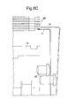
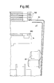
figures 6, 6B, 6C ,6D ,6E show construction details of the printer offigure 1 ; -
figure 7 shows the construction details offigures 6, 6B, 6C during cooperation with a table; -
figure 8 shows the construction details offigures 6, 6B, 6C during operation thereof; -
figures 8B ,8C ,8D ,8E and8F show various operating steps of the details shown infigure 8 ; -
figure 9 shows a table during advancement within the printer offigure 1 ; -
figures 10, 11 ,11B and12 show other construction details of the printer offigure 1 . - With reference to the figures, an embodiment of a printer according to the present invention is shown with 10 and a table structure for supporting and supplying support groups in
such printer 10 is shown with 100. -
Such printer 10 comprises ahousing 11, or loader, for receiving a plurality of tables 100 arranged one over the other, means 12 for the orientation of the tables 100 in thehousing 11, means 13 for supplying one table 100 at a time from thehousing 11 to an advancingplane 14 towards aprinting head 15 and means 16 for moving such single table 100 unloaded on the advancingplane 14. - A
rib 12, observable infigures 1 and3 , projecting within thehousing 11 can be provided asmeans 12 for the orientation of the tables 100 in thehousing 11 with respect to theprinter 10. - In particular,
such rib 12 develops parallel to the direction of arrangement of the tables 100 placed one over the other and cooperates with acorresponding groove 102, shown infigure 2 , obtained laterally with respect to the tables 100. - In
figure 3 it is observable how therib 12 engages the entire stack of tables 100, so that the tables 100 can be loaded in theprinter 10 solely in a given direction. - This allows avoiding erroneously loading of the tables 100 in the
printer 10.
In the present invention themeans 13 for supplying one table 100 at a time from thehousing 11 to the advancingplane 14 towards saidprinting head 15 compriseleafing devices 13 arranged laterally and in a lower portion of thehousing 11, so that the tables 100 inserted in the loader are supported on leafingdevices 13 without coming to contact with theplane 14, arranged partly beneath the housing. - In particular,
such leafing devices 13 are mobile between a first extracted position, in which they maintain the stack of tables 100 lifted, and a second retracted position, in which they drop-release one table 100 at a time from thehousing 11 to the advancingplane 14. - As observable in
figures 6B, 6C and8 , each of saidleafing devices 13 comprises twoblade elements upper blade 20 recedes into the structure of the printer and the table 100 resting thereon descends supported by the surfaces withlower thickness 105 on thelower blade 21. - At this point, the
upper blade 20 projects once again being positioned between the table 100 during the unloading step and the immediately upper one. Simultaneously, or immediately thereafter, thelower blade 21 recedes dropping the table 100 to be printed from thehousing 11 to thesupply plane 14. - The abovementioned steps of coordinated movement of the
blades 20 21 are shown in sequence infigures 8B ,8C ,8D ,8E and8F . - As shown in the abovementioned figures, preferably the movement of the
blades 20 21 is carried out by means ofcam pushers 40 operating independently, but in a synchronized manner, on theblades 20 21. - As observable in
figure 7 , theleafing devices 13 are preferably three and arranged on the sides parallel to the printing direction, two ofsuch leafing devices 13 being on one side and one on the opposite side at therecessions 105 in the tables 100. - The number thereof allows ensuring that the tables 100 always rest on all the
leafing devices 13 present. Pushing means 16 provided withportions 22 for restraining the tables 100 adherent to the advancingplane 14 are provided asmeans 16 for moving the single table 100 on the advancingplane 14. - Thus, the pushing means 16 push the table 100 towards the
printing head 15 and simultaneously prevent the table 100 from lifting during the movement steps. - Upon completing the printing step, the pushing means 16 return to the initial position to receive a new table 100.
- In order to make the
printer 10 adaptable to different thickness of the tables 100 and to prevent inadvertent collisions of theprinting head 15 with the table 100, the distance between theprinting head 15 and theabutment 41 is fixed orthogonally to the advancing direction of the tables 100 and the advancingplane 14 is mobile orthogonally to the advancing direction of the tables 100 up to bringing the tables at contact against anabutment 41, in turn fixed at a predefined distance suitable for the correct deposit of ink on the table 100. - Thus, the
abutment 41 prevents any possible collision of theprinting head 15 with the table 100 and simultaneously blocks the tables 100 regardless of the thickness thereof still at a predefined distance suitable for the correct deposit of ink. - Thus, advantageously the machine does not require any calibration upon variation of the thickness of the supplied tables.
- The
printing head 15 of the present invention is mobile only parallel to the advancingplane 14 and blocked in the direction of approaching or moving away from the tables 100. - Thus, generally, the
printer 10 for groups ofproducts 101 supported on atable structure 100 according to the present invention comprises at least one opening 11 for supplying the tables 100 and means 16 for moving the tables 100 towards theprinting head 15 and, at theprinting head 15, means are provided for moving the tables 100 with respect to theprinting head 15 mobile between a first position, in which the tables are at a distal position with respect to theprinting head 15, and a second position in which the tables are at a proximal position with respect to theprinting head 15. In such second position, the tables 100 are at contact with theabutment 41 arranged at a predetermined distance with respect to theprinting head 15. According to a preferred embodiment, also theabutment 41 can be mobile with respect to the printing head to offer the printer 10 a further adaptability to all types of tables. - The advancement of the table 100 on the
plane 14 is also controlled by means of aguide 24 for receivingpins such guide 24 narrows starting from thehousing 11 towards theprinting head 15 to perfectly centre the table 100 during printing. - As shown in
figure 4C , at the centring and slidingpins seats pins - Lastly, in the
printer 10 an area is also provided, shown infigure 12 , for possible manual supply of the tables 100 or parts thereof on theplane 14. - As partly evincible from the description of the printer, a
table structure 100 for supporting and supplying products insuch printer 10 is also an object of the present invention. - As observable in
figures 4, 4B ,5, 5B, 5C, 5D ,such table structure 100 comprises a frameperipheral portion 104 for supporting a plurality ofproducts 101 to be printed, where theframe 104 is provided with agroove 102 for coupling with therib 12 of thehousing 11, with areas havinglow thickness 105 for cooperation with theleafing devices 13, with sliding and centringpins 106 in theguide 24 obtained on theplane 14 and withpins 107 for centring the tables 100 with respect to each other in thehousing 11. - Furthermore, the
frame 104 may also comprise ahole 108 for moving the table 100. - Thus, the operation of a printer for products supported on a table subject of the invention is easy to understand.
- Actually, during the step of depositing ink, the printing head is fixed orthogonally to the advancing direction of the tables and the table is moved towards such head up to contact with an abutment arranged at a predetermined distance from the printing head.
- It has thus been observed that a printer and a table structure for supporting and supplying support groups in such printer according to the present invention attain the previously described objects.
- Actually, during the step of depositing ink, the distance between the table and the printing head is always suitable for the correct deposit of ink regardless of the thickness of the table and without requiring any calibration of the printer.
- The printer for products supported on a table of the present invention thus conceived is susceptible to numerous modifications and variants, all falling within the same inventive concept; furthermore, all details can be replaced by technically equivalent elements. In practice, the materials used as well as the dimensions thereof may vary according to the technical requirements.
Claims (10)
- Printer (10) for groups of products (101) supported on a table structure (100) comprising at least an opening (11) for supplying of said tables (100) and an advancing plane (14) of a single table (100) towards a printing head (15), characterized in that said printing head (15) is mobile only parallel to said advancing plane (14) and that, by said printing head (15), are foreseen means for moving said table (100) as regard to said printing head (15) mobile between a first position, in which said table (100) is in a distal position as regard to said printing head (15), and a second position in which said table (100) is in a proximal position as regard to said printing head (15), in said second position said table (100) being in touch with an abutment (41) placed at a predetermined distance as regard to said printing head (15).
- Printer (10) according to claim 1 characterized in that said abutment (41) is mobile in approaching and removal as regard to said printing head (15).
- Printer (10) according to any of the preceding claims characterized in that it comprises a housing (11) for receiving of a plurality of said tables (100) placed one on another, means for orientation (12) of said tables (100) in said housing (11) as regard to said printer (10), means for supplying (13) of one table (100) at a time from said housing (11) to said advancing plane (14) towards a printer head (15).
- Printer (10) according to claim 3 characterized in that said means for orientation (12) of said tables (100) in said housing (11) as regard to said printer (10) comprise a rib (12) projecting in said housing (11) that develops parallel to the way of disposition of said tables (100) placed one on another, said rib (12) being in cooperation with a corresponding groove (102) obtained laterally to said tables (100).
- Printer (10) according to claims 3 or 4 characterized in that said means for supplying (13) of one table at a time from said housing to said advancing plane towards said printing head comprise leafing devices (13) placed laterally and in a lower portion of said housing (11), said leafing devices (13) being mobile between a first position in which they maintain lifted the pile of said tables (100) from said advancing plane (14) and a second position in which a single table drops (100) from said housing (11) on said advancing plane (14).
- Printer (10) according to claim 5 characterized in that each of said leafing devices (13) comprise two blade elements (20, 21) placed one on another independently mobile.
- Printer (10) according to claim 1 characterized in that it comprises pushers (16) of said tables (100) on said advancing plane (14), said pushers (16) being provided with restraining portions (22) of said tables (100) adherent to said advancing plane (14).
- Printer (10) according to any of the preceding claims characterized in that said advancing plane (14) is mobile orthogonally to the advancing direction of said tables (100) in approaching and removal as regard to said printing head (15).
- Printer (10) according to any of the preceding claims characterized in that said advancing plane (14) comprises a guide (24) for receiving of pins (103) obtained on the lower surface of said tables (100).
- Printer (10) according to claim 9 characterized in that said guide (24) narrows from said housing (11) towards said printer head (15).
Applications Claiming Priority (1)
| Application Number | Priority Date | Filing Date | Title |
|---|---|---|---|
| ITMI2010A000603A IT1399220B1 (en) | 2010-04-09 | 2010-04-09 | PRINTER FOR GROUPS OF PRODUCTS SUPPORTED ON A TABLE STRUCTURE |
Publications (1)
| Publication Number | Publication Date |
|---|---|
| EP2374624A1 true EP2374624A1 (en) | 2011-10-12 |
Family
ID=42988337
Family Applications (1)
| Application Number | Title | Priority Date | Filing Date |
|---|---|---|---|
| EP11159397A Withdrawn EP2374624A1 (en) | 2010-04-09 | 2011-03-23 | Printer for groups of products supported on a table structure |
Country Status (6)
| Country | Link |
|---|---|
| US (1) | US8646858B2 (en) |
| EP (1) | EP2374624A1 (en) |
| KR (1) | KR20110113586A (en) |
| CN (1) | CN102211468A (en) |
| BR (1) | BRPI1101877A2 (en) |
| IT (1) | IT1399220B1 (en) |
Families Citing this family (2)
| Publication number | Priority date | Publication date | Assignee | Title |
|---|---|---|---|---|
| CN102529425A (en) * | 2011-11-18 | 2012-07-04 | 南京德众数码科技有限公司 | Continuous type platform printing device |
| CN109049989A (en) * | 2018-07-25 | 2018-12-21 | 韩智强 | A kind of printer calibrating installation |
Citations (3)
| Publication number | Priority date | Publication date | Assignee | Title |
|---|---|---|---|---|
| EP1036661A2 (en) * | 1999-03-16 | 2000-09-20 | Riso Kagaku Corporation | Sheet supply apparatus |
| US6499842B1 (en) * | 1999-10-15 | 2002-12-31 | Chocolate Printing Company | Foodstuffs imaging process and apparatus |
| US6536345B1 (en) * | 1994-07-29 | 2003-03-25 | Cadex Limited | Printing on the surface of edible substrates |
Family Cites Families (5)
| Publication number | Priority date | Publication date | Assignee | Title |
|---|---|---|---|---|
| DE2722060C2 (en) * | 1977-05-16 | 1982-10-07 | Mathias 4815 Schloss Holte Mitter | Frame for flat screen stencils for the stacked arrangement of several stencils in a screen printing machine |
| JPH01118460A (en) * | 1987-10-30 | 1989-05-10 | Brother Ind Ltd | Sheet feeder for printer |
| GB2291838B (en) * | 1994-07-29 | 1998-11-18 | Robert John Young | A machine and method for printing on an edible substrate |
| US5927545A (en) * | 1997-10-10 | 1999-07-27 | Pearson; Walter G. | Medication delivery cartridge |
| AT501863B1 (en) * | 2005-05-25 | 2007-08-15 | Durst Phototech Digital Tech | HOLDING DEVICE FOR INK JET PRINTER |
-
2010
- 2010-04-09 IT ITMI2010A000603A patent/IT1399220B1/en active
-
2011
- 2011-03-23 EP EP11159397A patent/EP2374624A1/en not_active Withdrawn
- 2011-03-24 US US13/065,539 patent/US8646858B2/en not_active Expired - Fee Related
- 2011-03-28 CN CN2011100751115A patent/CN102211468A/en active Pending
- 2011-03-28 BR BRPI1101877-1A patent/BRPI1101877A2/en not_active IP Right Cessation
- 2011-04-08 KR KR1020110032598A patent/KR20110113586A/en not_active Application Discontinuation
Patent Citations (3)
| Publication number | Priority date | Publication date | Assignee | Title |
|---|---|---|---|---|
| US6536345B1 (en) * | 1994-07-29 | 2003-03-25 | Cadex Limited | Printing on the surface of edible substrates |
| EP1036661A2 (en) * | 1999-03-16 | 2000-09-20 | Riso Kagaku Corporation | Sheet supply apparatus |
| US6499842B1 (en) * | 1999-10-15 | 2002-12-31 | Chocolate Printing Company | Foodstuffs imaging process and apparatus |
Also Published As
| Publication number | Publication date |
|---|---|
| CN102211468A (en) | 2011-10-12 |
| US20110249061A1 (en) | 2011-10-13 |
| ITMI20100603A1 (en) | 2011-10-10 |
| KR20110113586A (en) | 2011-10-17 |
| IT1399220B1 (en) | 2013-04-11 |
| BRPI1101877A2 (en) | 2012-10-30 |
| US8646858B2 (en) | 2014-02-11 |
Similar Documents
| Publication | Publication Date | Title |
|---|---|---|
| US20180376630A1 (en) | Tape cutting processing apparatus and processing method | |
| US10321619B2 (en) | Feeder | |
| KR101850256B1 (en) | Method for feeding a machine with sheet elements, feed station and treatment machine equipped therewith | |
| CN103193095A (en) | Automatic media loading and unloading system for producing dimensional documents | |
| EP2374624A1 (en) | Printer for groups of products supported on a table structure | |
| KR101429014B1 (en) | FPC Tray Feeding Apparatus | |
| JP5975792B2 (en) | Printing device | |
| US9003969B2 (en) | Device for loading printing plates on a plate cylinder of a rotary offset press | |
| EP2374623B1 (en) | Printer and table structure for supporting and supplying groups of products in such a printer | |
| US11794485B2 (en) | Food product printer | |
| JP2010189182A (en) | Paper receiving device and printer | |
| JP5294897B2 (en) | Paper receiving method in paper receiving device | |
| KR20160060491A (en) | cardboard division supply system | |
| JP2011003566A (en) | Tray supply device and component mounting device | |
| JP6679984B2 (en) | Transport system | |
| JP2016069126A (en) | Printed book accumulation apparatus and printed book accumulation method | |
| CA2899639A1 (en) | Apparatus for marking and ordering plate blanks, and load and receiving magazines therefor | |
| JP2012254806A (en) | Pallet for loading paper | |
| JPH06144578A (en) | Pallet feeding device | |
| CN114829276A (en) | Device and method for replacing a stack of sheets in a stack feeder | |
| JP2017071464A (en) | Paper feeder and sheet placing plate | |
| JP2016052920A (en) | Material supplying device | |
| IE20070455U1 (en) | Apparatus for stacking articles | |
| JPH05254679A (en) | Feeder for sheet material | |
| IES85026Y1 (en) | Apparatus for stacking articles |
Legal Events
| Date | Code | Title | Description |
|---|---|---|---|
| PUAI | Public reference made under article 153(3) epc to a published international application that has entered the european phase |
Free format text: ORIGINAL CODE: 0009012 |
|
| AK | Designated contracting states |
Kind code of ref document: A1 Designated state(s): AL AT BE BG CH CY CZ DE DK EE ES FI FR GB GR HR HU IE IS IT LI LT LU LV MC MK MT NL NO PL PT RO RS SE SI SK SM TR |
|
| AX | Request for extension of the european patent |
Extension state: BA ME |
|
| 17P | Request for examination filed |
Effective date: 20120322 |
|
| RIC1 | Information provided on ipc code assigned before grant |
Ipc: B41J 13/10 20060101ALI20131209BHEP Ipc: B41J 13/16 20060101ALI20131209BHEP Ipc: B41J 3/28 20060101AFI20131209BHEP |
|
| GRAP | Despatch of communication of intention to grant a patent |
Free format text: ORIGINAL CODE: EPIDOSNIGR1 |
|
| INTG | Intention to grant announced |
Effective date: 20140120 |
|
| STAA | Information on the status of an ep patent application or granted ep patent |
Free format text: STATUS: THE APPLICATION IS DEEMED TO BE WITHDRAWN |
|
| 18D | Application deemed to be withdrawn |
Effective date: 20140603 |