EP2374567A1 - Soldering apparatus with calculation unit for obtaining information of its consumed electric energy - Google Patents
Soldering apparatus with calculation unit for obtaining information of its consumed electric energy Download PDFInfo
- Publication number
- EP2374567A1 EP2374567A1 EP20110161785 EP11161785A EP2374567A1 EP 2374567 A1 EP2374567 A1 EP 2374567A1 EP 20110161785 EP20110161785 EP 20110161785 EP 11161785 A EP11161785 A EP 11161785A EP 2374567 A1 EP2374567 A1 EP 2374567A1
- Authority
- EP
- European Patent Office
- Prior art keywords
- electric energy
- consumed electric
- soldering apparatus
- unit
- amount
- Prior art date
- Legal status (The legal status is an assumption and is not a legal conclusion. Google has not performed a legal analysis and makes no representation as to the accuracy of the status listed.)
- Granted
Links
Images



Classifications
-
- B—PERFORMING OPERATIONS; TRANSPORTING
- B23—MACHINE TOOLS; METAL-WORKING NOT OTHERWISE PROVIDED FOR
- B23K—SOLDERING OR UNSOLDERING; WELDING; CLADDING OR PLATING BY SOLDERING OR WELDING; CUTTING BY APPLYING HEAT LOCALLY, e.g. FLAME CUTTING; WORKING BY LASER BEAM
- B23K1/00—Soldering, e.g. brazing, or unsoldering
- B23K1/008—Soldering within a furnace
-
- B—PERFORMING OPERATIONS; TRANSPORTING
- B23—MACHINE TOOLS; METAL-WORKING NOT OTHERWISE PROVIDED FOR
- B23K—SOLDERING OR UNSOLDERING; WELDING; CLADDING OR PLATING BY SOLDERING OR WELDING; CUTTING BY APPLYING HEAT LOCALLY, e.g. FLAME CUTTING; WORKING BY LASER BEAM
- B23K1/00—Soldering, e.g. brazing, or unsoldering
- B23K1/0008—Soldering, e.g. brazing, or unsoldering specially adapted for particular articles or work
-
- B—PERFORMING OPERATIONS; TRANSPORTING
- B23—MACHINE TOOLS; METAL-WORKING NOT OTHERWISE PROVIDED FOR
- B23K—SOLDERING OR UNSOLDERING; WELDING; CLADDING OR PLATING BY SOLDERING OR WELDING; CUTTING BY APPLYING HEAT LOCALLY, e.g. FLAME CUTTING; WORKING BY LASER BEAM
- B23K1/00—Soldering, e.g. brazing, or unsoldering
- B23K1/0008—Soldering, e.g. brazing, or unsoldering specially adapted for particular articles or work
- B23K1/0016—Soldering of electronic components
-
- B—PERFORMING OPERATIONS; TRANSPORTING
- B23—MACHINE TOOLS; METAL-WORKING NOT OTHERWISE PROVIDED FOR
- B23K—SOLDERING OR UNSOLDERING; WELDING; CLADDING OR PLATING BY SOLDERING OR WELDING; CUTTING BY APPLYING HEAT LOCALLY, e.g. FLAME CUTTING; WORKING BY LASER BEAM
- B23K1/00—Soldering, e.g. brazing, or unsoldering
- B23K1/002—Soldering by means of induction heating
-
- B—PERFORMING OPERATIONS; TRANSPORTING
- B23—MACHINE TOOLS; METAL-WORKING NOT OTHERWISE PROVIDED FOR
- B23K—SOLDERING OR UNSOLDERING; WELDING; CLADDING OR PLATING BY SOLDERING OR WELDING; CUTTING BY APPLYING HEAT LOCALLY, e.g. FLAME CUTTING; WORKING BY LASER BEAM
- B23K1/00—Soldering, e.g. brazing, or unsoldering
- B23K1/012—Soldering with the use of hot gas
-
- B—PERFORMING OPERATIONS; TRANSPORTING
- B23—MACHINE TOOLS; METAL-WORKING NOT OTHERWISE PROVIDED FOR
- B23K—SOLDERING OR UNSOLDERING; WELDING; CLADDING OR PLATING BY SOLDERING OR WELDING; CUTTING BY APPLYING HEAT LOCALLY, e.g. FLAME CUTTING; WORKING BY LASER BEAM
- B23K3/00—Tools, devices or special appurtenances for soldering, e.g. brazing, or unsoldering, not specially adapted for particular methods
- B23K3/04—Heating appliances
- B23K3/047—Heating appliances electric
-
- B—PERFORMING OPERATIONS; TRANSPORTING
- B23—MACHINE TOOLS; METAL-WORKING NOT OTHERWISE PROVIDED FOR
- B23K—SOLDERING OR UNSOLDERING; WELDING; CLADDING OR PLATING BY SOLDERING OR WELDING; CUTTING BY APPLYING HEAT LOCALLY, e.g. FLAME CUTTING; WORKING BY LASER BEAM
- B23K3/00—Tools, devices or special appurtenances for soldering, e.g. brazing, or unsoldering, not specially adapted for particular methods
- B23K3/04—Heating appliances
- B23K3/047—Heating appliances electric
- B23K3/0475—Heating appliances electric using induction effects, e.g. Kelvin or skin effects
-
- B—PERFORMING OPERATIONS; TRANSPORTING
- B23—MACHINE TOOLS; METAL-WORKING NOT OTHERWISE PROVIDED FOR
- B23K—SOLDERING OR UNSOLDERING; WELDING; CLADDING OR PLATING BY SOLDERING OR WELDING; CUTTING BY APPLYING HEAT LOCALLY, e.g. FLAME CUTTING; WORKING BY LASER BEAM
- B23K3/00—Tools, devices or special appurtenances for soldering, e.g. brazing, or unsoldering, not specially adapted for particular methods
- B23K3/08—Auxiliary devices therefor
-
- G—PHYSICS
- G01—MEASURING; TESTING
- G01N—INVESTIGATING OR ANALYSING MATERIALS BY DETERMINING THEIR CHEMICAL OR PHYSICAL PROPERTIES
- G01N29/00—Investigating or analysing materials by the use of ultrasonic, sonic or infrasonic waves; Visualisation of the interior of objects by transmitting ultrasonic or sonic waves through the object
- G01N29/04—Analysing solids
- G01N29/11—Analysing solids by measuring attenuation of acoustic waves
-
- G—PHYSICS
- G01—MEASURING; TESTING
- G01N—INVESTIGATING OR ANALYSING MATERIALS BY DETERMINING THEIR CHEMICAL OR PHYSICAL PROPERTIES
- G01N29/00—Investigating or analysing materials by the use of ultrasonic, sonic or infrasonic waves; Visualisation of the interior of objects by transmitting ultrasonic or sonic waves through the object
- G01N29/04—Analysing solids
- G01N29/12—Analysing solids by measuring frequency or resonance of acoustic waves
-
- G—PHYSICS
- G01—MEASURING; TESTING
- G01N—INVESTIGATING OR ANALYSING MATERIALS BY DETERMINING THEIR CHEMICAL OR PHYSICAL PROPERTIES
- G01N29/00—Investigating or analysing materials by the use of ultrasonic, sonic or infrasonic waves; Visualisation of the interior of objects by transmitting ultrasonic or sonic waves through the object
- G01N29/22—Details, e.g. general constructional or apparatus details
- G01N29/30—Arrangements for calibrating or comparing, e.g. with standard objects
-
- G—PHYSICS
- G01—MEASURING; TESTING
- G01R—MEASURING ELECTRIC VARIABLES; MEASURING MAGNETIC VARIABLES
- G01R33/00—Arrangements or instruments for measuring magnetic variables
- G01R33/02—Measuring direction or magnitude of magnetic fields or magnetic flux
- G01R33/06—Measuring direction or magnitude of magnetic fields or magnetic flux using galvano-magnetic devices
- G01R33/07—Hall effect devices
-
- B—PERFORMING OPERATIONS; TRANSPORTING
- B23—MACHINE TOOLS; METAL-WORKING NOT OTHERWISE PROVIDED FOR
- B23K—SOLDERING OR UNSOLDERING; WELDING; CLADDING OR PLATING BY SOLDERING OR WELDING; CUTTING BY APPLYING HEAT LOCALLY, e.g. FLAME CUTTING; WORKING BY LASER BEAM
- B23K2101/00—Articles made by soldering, welding or cutting
- B23K2101/36—Electric or electronic devices
- B23K2101/42—Printed circuits
-
- H—ELECTRICITY
- H05—ELECTRIC TECHNIQUES NOT OTHERWISE PROVIDED FOR
- H05K—PRINTED CIRCUITS; CASINGS OR CONSTRUCTIONAL DETAILS OF ELECTRIC APPARATUS; MANUFACTURE OF ASSEMBLAGES OF ELECTRICAL COMPONENTS
- H05K3/00—Apparatus or processes for manufacturing printed circuits
- H05K3/30—Assembling printed circuits with electric components, e.g. with resistors
- H05K3/32—Assembling printed circuits with electric components, e.g. with resistors electrically connecting electric components or wires to printed circuits
- H05K3/34—Assembling printed circuits with electric components, e.g. with resistors electrically connecting electric components or wires to printed circuits by soldering
- H05K3/3494—Heating processes for reflow soldering
-
- Y—GENERAL TAGGING OF NEW TECHNOLOGICAL DEVELOPMENTS; GENERAL TAGGING OF CROSS-SECTIONAL TECHNOLOGIES SPANNING OVER SEVERAL SECTIONS OF THE IPC; TECHNICAL SUBJECTS COVERED BY FORMER USPC CROSS-REFERENCE ART COLLECTIONS [XRACs] AND DIGESTS
- Y10—TECHNICAL SUBJECTS COVERED BY FORMER USPC
- Y10T—TECHNICAL SUBJECTS COVERED BY FORMER US CLASSIFICATION
- Y10T29/00—Metal working
- Y10T29/53—Means to assemble or disassemble
- Y10T29/53022—Means to assemble or disassemble with means to test work or product
Definitions
- the present invention contains subject matter related to Japanese Patent Application JP 2010-090968 filed in the Japanese Patent Office on April 9, 2010.
- the present invention relates to a soldering apparatus.
- a reflow soldering apparatus When soldering the electronic components on a printed circuit board, a reflow soldering apparatus is generally used.
- a reflow soldering apparatus includes a conveyor conveying the printed circuit boards and a main body of the reflow soldering apparatus into which the conveyor conveys the print circuited boards.
- the main body of the reflow soldering apparatus is partitioned into three zones, namely, a preliminary heating zone, a main heating zone and a cooling zone therein.
- each of the preliminary heating and main heating zones contains heaters, temperature controllers, motors and inverters.
- the cooling zone contains cooling fans and inverters. Any electronic components are mounted on the printed circuit board on which solder paste has been previously printed. The printed circuit board is then subjected to the heating in the soldering apparatus, so that the electronic components can be soldered on the printed circuit board.
- the general reflow soldering apparatus is equipped with electricity meters that measures an amount of consumed electrical energy in the operation of the reflow soldering apparatus.
- electricity meters that measures an amount of consumed electrical energy in the operation of the reflow soldering apparatus.
- Each of the temperature controllers that control temperatures of the above-mentioned heaters or each of the inverters that control rotations of the motors driving the fans is equipped with such an electricity meter.
- the electricity meter displays the amount of consumed electrical energy of each of the heaters or fans.
- Such a measurement is also performed in a flow type soldering apparatus in which solder melted within a solder bath is flown and electronic components are soldered on the printed circuit board by contacting a lower surface of the printed circuit board to a top layer of flown solder.
- This flow soldering apparatus (including partial soldering apparatus of the printed circuit board) is provided with a fluxer, preheaters, a flow solder bath, cooling device and the like.
- the preheaters are connected with the temperature controller that controls temperature thereof.
- the flow solder bath is connected with an inverter that controls a number of revolutions of each of the motors which drive screws.
- the temperature controller and the inverter are respectively equipped with the above-mentioned electricity meters which indicate the amount of consumed electrical energy of each of the heaters or motors.
- Japanese Patent Application Publication No. H07-212027 has disclosed a heaters-starting-up method in which in a reflow soldering apparatus, heaters provided in the furnace start up with starting-up time of each heater being staggered so that a total amount of current of the heaters at the starting-up time thereof may be reduced.
- the temperature controller, the inverter and the like may be respectively required so to be equipped with the above-mentioned electricity meters. This may cause an increase in costs in accordance with numbers of equipped electricity meters. Further, each device is equipped with electricity meter, which increases spaces for equipping the electricity meters excessively.
- embodiments of the present invention can solve or at least alleviate the above-mentioned problems and can provide a soldering apparatus that allows any costs to be reduced and/or allows any spaces to be reduced in a case of obtaining the consumed electrical energy of the soldering apparatus.
- a soldering apparatus that solders an electronic component on a circuit board using a solder composition.
- the soldering apparatus contains a soldering unit that solders the electronic component on the circuit board and a detection unit that detects information of consumed electric energy, the information relating to an amount of the consumed electric energy of the soldering unit.
- the soldering apparatus also contains a calculation unit that obtains the information of consumed electric energy of the soldering unit which is detected by the detection unit and calculates the amount of the consumed electric energy of the soldering unit based on the obtained information of consumed electric energy of the soldering unit, and a display unit that displays on a screen thereof the amount of the consumed electric energy of the soldering unit, which is calculated by the calculation unit.
- the soldering apparatus contains a reflow soldering apparatus that solders an electronic component(s) on a circuit board to which the solder composition is previously applied, and a flow soldering apparatus that solders an electronic component (s), which is previously mounted on a circuit board, on the circuit board by flowing solder melted in a solder bath.
- the soldering unit such as heaters and fans solders the electronic component(s) on the circuit board conveyed into the soldering apparatus under heating processing, cooling processing and/or the like.
- the detection unit detects information of consumed electric energy. This information relates to an amount of the consumed electric energy of the soldering unit during soldering processing.
- the detection unit includes a temperature controller that controls temperature of heaters and an inverter that controls a number of revolutions of each motor.
- the information of consumed electric energy of the soldering unit includes an amount of operation of the temperature controller, a value of current from the inverter and a predetermined coefficient of the consumed electric energy.
- the calculation unit obtains the information of consumed electric energy of the soldering unit which is detected by the detection unit and calculates the amount of the consumed electric energy of the soldering unit based on the obtained information of consumed electric energy of the soldering unit.
- the display unit displays on a screen thereof the amount of the consumed electric energy of the soldering unit, which is calculated by the calculation unit.
- the detection unit also detects information on consumed electric energy of the detection unit itself.
- the calculation unit obtains the information of consumed electric energy of the soldering unit and the information of consumed electric energy of the detection unit and calculates a total amount of the consumed electric energy of the soldering apparatus based on the obtained information of the consumed electric energy of the soldering unit and the obtained information of the consumed electric energy of the detection unit.
- the display unit displays the total amount of the total amount of the consumed electric energy of the soldering apparatus, which is calculated by the calculation unit.
- the calculation unit calculates amounts of the consumed electric energy of the soldering unit and the detection unit and the total amount of the total amount of the consumed electric energy of the soldering apparatus.
- the display unit displays the amounts of the consumed electric energy of the soldering unit and the detection unit and the total amount of the total amount of the consumed electric energy of the soldering apparatus, which have been calculated by the calculation unit.
- Embodiments of the invention therefore relate to a soldering apparatus that solders electronic components on a circuit board using solder composition.
- a reflow soldering apparatus 100 as a first embodiment of the invention obtains an amount of operation Dtr indicating consumed electric energy of heaters 12 from temperature controllers 20, an amount of current Dir indicating consumed electric energy of the motors 16, each of which drives fan 14, from inverters 22 and the like.
- the reflow soldering apparatus 100 calculates an amount of the consumed electric energy of heaters 12 and an amount of the consumed electric energy of the motors 16 and adds up amounts of the consumed electric energy thus calculated to display a total amount of consumed energy of the soldering apparatus on a screen of an operation/display unit 30.
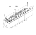
- the reflow soldering apparatus 100 contains a main body (muffle furnace) 10 of the reflow soldering apparatus, a conveyor 28, and the operation/display unit 30, as shown in FIG. 1 .
- the main body 10 of the reflow soldering apparatus 100 is formed of a tunnel-like housing including the entrance 10a and the exit 10b.
- the inside of the main body 10 of the reflow soldering apparatus 100 is partitioned into three zones, namely, a preliminary heating zone Z1, a main heating zone Z2 and a cooling zone Z3, along the conveying route of the circuit board from the entrance 10a up to the exit 10b.
- the conveyor 28 extends along the conveying route from the entrance 10a up to the exit 10b and conveys each of the printed circuit boards 40 at a predetermined speed from the entrance 10a of the main body 10 of the reflow soldering apparatus 100 to the exit 10b thereof (along a direction of an arrow X).
- the printed circuit board 40 on which surface-mountable electronic components are mounted is set on the conveyor 28, the printed circuit board 40 is conveyed to enter into the main body 10 of the reflow soldering apparatus 100 through the entrance 10a.
- heated air is blown upon the printed circuit board 40. This enables flux to be activated. This also enables to be deleted an oxidation layer on a surface of electrode or solder paste.
- the solder is melted so that electronic components can be fixed on electrodes of the printed circuit board 40.
- the printed circuit board 40 is cooled so that the solder can be solidified.
- the printed circuit board 40 cooled through the cooling zone Z3 is discharged from the exit 10b.
- the reflow soldering apparatus 100 contains a power source unit 32, a control unit 24, heaters 12, temperature controllers 20, motors 18, fans 14, inverters 22, cooling devices 18, a calculation unit 26 of consumed electric energy and an operation/display unit 30.
- the heaters 12, the motors 16 and the fans 14 constitute a soldering unit as an example thereof.
- the temperature controllers 20, the inverters 22 and the control unit 24 constitute a detection unit as an example thereof.
- the power source unit 32 is connected to the control unit 24, the heaters 12, the temperature controllers 20, the motors 16, the fans 14, the inverters 22, the cooling devices 18, the calculation unit 26 of consumed electric energy and the operation/display unit 30, respectively and supplies power source to each of the parts.
- the control unit 24 is composed of a personal computer or the like, which includes a central processing unit (CPU), a read only memory (ROM), a random access memory (RAM). This control unit 24 is connected to the temperature controllers 20, the inverters 22 and the calculation unit 26 of consumed electric energy and controls operations of the temperature controllers 20, the inverters 22 and the calculation unit 26 of consumed electric energy. Since consumed electric energy of the control unit 24 is changed within a fixed range thereof, a fixed amount of the consumed electric energy is previously set as a coefficient Dpr of consumed electric energy. The control unit 24 reads the coefficient Dpr of consumed electric energy recorded in a memory to output it to the calculation unit 26 of consumed electric energy.
- CPU central processing unit
- ROM read only memory
- RAM random access memory
- Pairs of the heaters 12 are disposed on upper and lower positions of the conveyor 28 so that the heaters are opposed and heat air within the main body 10 of the reflow soldering apparatus 100 under power control of the temperature controllers 20 (for example, PID control).
- the temperature controllers 20 for example, PID control
- four pairs of the heaters 12 are disposed on upper and lower positions of the conveyor 28 in the preliminary heating zone Z1 and four pairs of the heaters 12 are disposed on upper and lower positions of the conveyor 28 in the main heating zone Z2.
- the preliminary heating zone Z1 and the main heating zone Z2 may often have the same configuration generally but they may have different configurations, a description of which will be omitted as a matter of convenience.
- the temperature controllers 20 that control temperature of the heaters 12 have temperature sensors and temperature adjustment units.
- the temperature controllers 20 are constituted of a pair of upper and lower temperature controllers.
- the temperature controllers 20 may be provided in each of the heating zones Z1 and Z2.
- Each of the temperature sensors is composed of a thermocouple or a thermistor and is set near the heater 12 to be controlled to measure temperature of the heater 12 or around the heater 12.
- the temperature adjustment units perform proportional, integral and derivative (PID) control based on temperature information detected by the temperature sensors. In the PID control, the amount of operation Dtr is adjusted so that it becomes a set temperature (target temperature).
- the amount of operation Dtr includes output voltage, output current or the like of each of the heaters 12, on which the temperature of each of the heaters 12 is set to the set temperature. Further, the temperature controllers 20 detect the amount of operation Dtr of the heaters 12 as an amount of temperature control thereof and output it to the calculation unit 26 of consumed electric energy.
- Pairs of the motors 16 are disposed on upper and lower positions of the conveyor 28 so that the motors are opposed and respectively drive under a frequency control by the inverters 22 to rotate the fans 14 at a predetermined number of revolutions.
- Each of the fans 14 is composed of, for example, a air-supplying fan such as a turbofan or a sirocco-fan and rotates by the rotation of each of the motors 16 to blow air heated by each of the heaters 12 to each of the upper and lower surfaces of the printed circuit board 40.
- the fans 14 and the motors 16 may have the different configurations in the preliminary heating zone Z1 and the main heating zone Z2 and they may have the same configuration but have different use conditions such as different power to be supplied, a description of which will be omitted as a matter of convenience.
- Each of the cooling devices 18 contains a motor, not shown, and a cooling fan, not shown, and drives the motor under a frequency control by the inverters 22 to rotate the cooling fan at a predetermined number of revolutions. This enables cooled air to be blown to the printed circuit board 40 so that the printed circuit board heated in the preliminary heating zone Z1 and the main heating zone Z2 can be cooled.
- the inverters 22 convert a frequency of power source (alter an amount of current Dir) based on any control information supplied from the control unit 24 to control the number of revolutions of each of the motors 16.
- a pair of the inverters each of which controls the upper motors or the lower motors, is used. It is to be noted that the inverter 22 may be provided on each of the motors 16.
- the inverters 22 detect and obtain the amount of current Dir output when they drive the motors 16 to output the amount of current Dir to the calculation unit 26 of consumed electric energy.
- the calculation unit 26 of consumed electric energy is connected to the temperature controllers 20, the inverters 22 and the control unit 24, respectively, and is composed of, for example, a computer having CPU, ROM RAM and the like.
- the calculation unit 26 of consumed electric energy obtains the amount of operation Dtr from the temperature controllers 20 and calculates consumed electric energy of the heaters 12 from output voltage, output current and the like included in the amount of operation Dtr thus obtained.
- the calculation unit 26 of consumed electric energy also obtains the amount of current Dir used for driving the motors 16 from the inverters 22 and calculates consumed electric energy of the motors 16 from the amount of current Dir thus obtained.
- the calculation unit 26 of consumed electric energy further obtains the coefficient Dpr of consumed electric energy read from the control unit 24 and calculates consumed electric energy of the control unit 24 from the coefficient Dpr of consumed electric energy thus obtained.
- Such consumed electric energy of the control unit 24 thus calculated includes consumed electric energy of parts other than the control unit 24 such as the temperature controllers 20 and/or the inverters 22.
- the calculation unit 26 of consumed electric energy adds up the calculated amount of consumed electric energy of the temperature controllers 20, the calculated amount of consumed electric energy of the inverter 22 and the calculated amount of consumed electric energy of the control unit 24 and the like to calculate a total amount of consumed electric energy of the reflow soldering apparatus 100.
- the calculation unit 26 of consumed electric energy then outputs the calculated total amount of consumed electric energy of the reflow soldering apparatus 100 to the operation/display unit 30 which displays the total amount of consumed electric energy of the reflow soldering apparatus 100 on a window of representing the consumed electric energy of the reflow soldering apparatus 100 in an operation screen of the operation/display unit 30.
- the operation/display unit 30 is composed of, for example, a touch panel operation device and a display device such as liquid crystal display or an organic electroluminescent display so that they are incorporated.
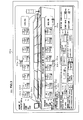
- the operation/display unit 30 displays the total amount of consumed electric energy of the reflow soldering apparatus 100 based on the information on consumed electric energy supplied from the calculation unit 26 of consumed electric energy on the operation screen of the operation/display unit 30 (see FIG. 3 ).
- the operation/display unit 30 also inputs setting of the temperature of each of the heating zones Z1 and Z2 and setting of an amount level of blown air and/or a conveying speed of the conveyor 28 by pressing pairs of up-down control arrow buttons and supplies the input operation information to the control unit 24.
- an image 30b of the reflow soldering apparatus 100 which indicates the reflow soldering apparatus 100 schematically, appears at a middle of the operation screen 30a of the operation/display unit 30.
- the reflow soldering apparatus having two upper and lower groups of the preliminary heating zone Z1 and the main heating zone Z2 is shown.
- letters 30c such as 1T through 8T indicating respective zones are shown at a top of each zone.
- Present temperature 30d indicating actual temperature of each zone is shown below the letters 30c of each of the zones 1T through 8T.
- Set temperature 30e of each of the zones 1T through 8T which a user sets is shown below the present temperature 30d.
- a pair of up-down arrow keys 30f is shown at right side of the set temperature 30e and by operating the up-down control arrow keys 30f, the set temperature 30e of each of the zones 1T through 8T can be adjusted for every one degree.
- Letters 30g indicating a level of an amount of revolution by the fan 14 are shown above and between the zones 4T and 5T.
- a pair of up-down control arrow keys 30h for adjusting the level of the amount of revolution by the fan 14 is shown at right side of the letters 30g.
- letters 30i such as 1B through 8B indicating respective zones are shown at a top of each zone in a casing shown in the image 30b of the reflow soldering apparatus.
- Present temperature 30j indicating actual temperature of each of the zones 1B through 8B is shown below the letters 30i of each of the zones 1B through 8B.
- Set temperature 30k of each of the zones 1B through 8B which a user sets is shown below the present temperature 30j.
- a pair of up-down arrow keys 30l is shown at right side of the set temperature 30k and by operating the up-down arrow keys 30l, the set temperature 30k of each of the zones 1B through 8B can be adjusted for every one degree.
- Letters 30m indicating a level of an amount of revolution by the fan 14 are shown below and between the zones 4B and 5B.
- a pair of up-down arrow keys 30n for adjusting the level of the amount of revolution by the fan 14 is shown at right side of the letters 30m.
- a representation window 30o for representing figure(s) indicating the total amount of consumed electric energy of reflow soldering apparatus 100 is shown at left side of the screen and below the image 30b of the reflow soldering apparatus 100.
- the representation window 30o the total amount of the consumed electric energy of reflow soldering apparatus 100, which have been calculated in the above-mentioned calculation unit 26 of consumed electric energy, is represented.
- the total amount of the consumed electric energy of reflow soldering apparatus 100 is updated and displayed on a real-time basis or at regular interval. It is to be noted that when the user selects the representation window 30o, a pop-up sub-screen for representing consumed electric energy of the heaters 12 or the motors 16 may be shown. Further, when the total amount of the consumed electric energy of reflow soldering apparatus 100 exceeds a predetermined value, the representation window 30o may be flushed or highlighted based on a determination of the calculation unit 26 of consumed electric energy and/or the control unit 24.
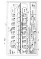
- a representation window for representing consumed electric energy of respective parts such as the heaters 12 or the motors 16 other than the representation window 30o indicating the total amount of consumed electric energy of reflow soldering apparatus 100 may be shown.
- a representation window 30p for representing consumed electric energy of the heaters 12 may be represented at a right side of the representation window 30o and a representation window 30q for representing consumed electric energy of the motors 16 may be represented at a right side of the representation window 30p.
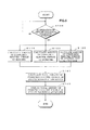
- the calculation unit 26 of consumed electric energy determines whether or not the operation of the reflow soldering apparatus 100 is started. For example, it determines whether or not the user selects an operation button for powering the power source on in the operation/display unit 30. If the calculation unit 26 of consumed electric energy determines that the operation of the reflow soldering apparatus 100 is started, then the operation goes to steps S110, S120 and S130, respectively. If the calculation unit 26 of consumed electric energy determines that the operation of the reflow soldering apparatus 100 is not started, then the operation waits until the operation of the reflow soldering apparatus 100 is started.
- the calculation unit 26 of consumed electric energy obtains the amount of operation Dtr from the temperature controllers 20 and calculates consumed electric energy of the heaters 12 from output voltage, output current and the like included in the amount of operation Dtr thus obtained.
- the calculation unit 26 of consumed electric energy obtains the amount of current Dir from the inverters 22 and calculates amount of consumed electric energy of the inverter 22 from the amount of current Dir thus obtained and the voltage value of the power source unit 32. This enables an amount of consumed electric energy of the fans 14 and the motors 16 disposed on upper and lower positions of the conveyor 28 of the preliminary heating zone Z1 and the main heating zone Z2.
- the calculation unit 26 of consumed electric energy obtains the coefficient Dpr of consumed electric energy from the temperature controllers 20, the inverters 22, the control unit 24 and the like and calculates amounts of consumed electric energy of the control unit 24 and the like from the coefficient Dpr of consumed electric energy thus obtained.
- the calculation unit 26 of consumed electric energy adds up the amount of consumed electric energy of the heaters 12 calculated at the step S110, the amount of consumed electric energy of the fan 14 calculated at the step S120 and the amount of consumed electric energy of the control unit 24 and the like calculated at the step S130 to calculate the total amount of consumed electric energy of the reflow soldering apparatus 100.
- the calculation unit 26 of consumed electric energy controls the operation/display unit 30 to display the total amount of consumed electric energy of the reflow soldering apparatus 100 thus calculated on the representation window 30o in the operation screen of the operation/display unit 30.
- Such a series of operations for calculating the total amount of the consumed electric energy of the reflow soldering apparatus 100 is performed on a real-time basis or at regular interval.
- the total amount of the consumed electric energy of the reflow soldering apparatus 100 is then displayed one by one on the operation screen 30a of the operation/display unit 30.
- the calculation unit 26 of consumed electric energy calculates amounts of consumed electric energy of the heaters 12 and the motors 16 and the operation/display unit 30 displays the calculated total amount of the consumed electric energy of the reflow soldering apparatus 100 on the representation window 30o of the operation/display unit 30.
- the flow soldering apparatus 200 contains the casing 50 of the main body of the flow soldering apparatus 200, a conveyor 86, preheaters 52, a flow solder bath 80, a cooling device 56 and an operation/display unit 60, as shown in FIG. 6 .
- the casing 50 of main body of the flow soldering apparatus 200 is a casing for covering whole of the conveyor 86, the preheaters 52, the flow solder bath 80, the cooling device 56, the operation/display unit 60 and the like and has a function of protecting a printed circuit board 62 so that any particles such as dirt entered from outside cannot be adhered to the printed circuit board 62.
- the operation/display unit 60 is composed of, for example, a touch panel operation device and a display device such as liquid crystal display or an organic electroluminescent display so that they are incorporated.
- the operation/display unit 60 is provided on a front surface of the casing 50 of main body of the flow soldering apparatus 200 and an entrance side thereof.
- the operation/display unit 60 displays the total amount of consumed electric energy of the flow soldering apparatus 200 based on the information on consumed electric energy supplied from the calculation unit 74 of consumed electric energy on the operation screen of the operation/display unit 30 (see FIG. 8 ).
- the preheaters 52 are used for allowing to dry the printed circuit board 62 to which flux is applied in a fluxing step that is a preceding step of a step where the printed circuit board on which electronic components, not shown, are mounted enters into the flow soldering apparatus 200.
- the preheaters 52 are also used for heating the printed circuit board 62 to enhance adhesion power in the solder.
- the flow solder bath 80 is disposed on a downstream side of the preheaters 52 along a conveying direction D2 of the printed circuit board 62.
- the flow solder bath 80 contains melted solder for soldering electronic components mounted on the printed circuit board 62 to the printed circuit board 62.
- any lead-free solder containing tin-silver-copper or tin-zinc-bismuth may be used as the melted solder.
- Such solder has a melting range of, for example, about 180°C through 220°C.
- the flow solder bath 80 is provided with a primary flow nozzle, not shown, for allowing the solder to flow and generating rough waves and a secondary flow nozzle, not shown, for allowing the solder to flow and generating smooth waves.
- the primary and secondary flow nozzles blow the melted solder to the printed circuit board 62 heated by the preheaters 52 at a flat level.
- the flow solder bath 80 is provided a heater(s), not shown. Temperature of this heater is controlled by a temperature controller 70 so that the heater can melt the solder and holds the solder at a predetermined temperature.
- the cooling device 56 is disposed on a downstream side of the flow solder bath 80 along a conveying direction D2 of the printed circuit board 62.
- the cooling device 56 cools the printed circuit board 62 heated by the preheaters 52 and the flow solder bath 80.
- the flow soldering apparatus 200 contains a power source unit 92, the conveyor 86, the preheaters 52, the temperature controller 70, a first pump 82A for flowing the melted solder from the primary flow nozzle, a second pump 82B for flowing the melted solder from the secondary flow nozzle, the cooling device 56, an inverter 68, a control unit 72, a calculation unit 74 of consumed electric energy and the operation/display unit 60.
- the power source unit 92 is connected to the preheaters 52, the temperature controller 70, the first pump 82A, the second pump 82B, the cooling device 56, the inverter 68, the control unit 72, the calculation unit 74 of consumed electric energy and the operation/display unit 60, respectively and supplies power source to each of the parts.
- four preheaters 52a, 52b, 52c and 52d constitute the preheaters 52 and are disposed so that they are adjacent to each other along the conveying direction D2 of the printed circuit board 62.
- the preheaters 52 heat air within the casing 50 of the main body of the flow soldering apparatus 200 under power control (for example, PID control) of the temperature controller 70.
- the temperature controller 70 controls temperature of the four preheaters 52a, 52b, 52c and 52d and has temperature sensors and temperature adjustment units, not shown.
- the temperature sensors are disposed on respective preheaters 52a, 52b, 52c and 52d to be controlled and measure temperature of each of the preheaters 52a, 52b, 52c and 52d.
- the temperature adjustment units perform PID control based on temperature information detected by the temperature sensors. In the PID control, the amount of operation Dtf is adjusted so that it becomes a set temperature (target temperature).
- the amount of operation Dtf includes output voltage, output current or the like of each of the preheaters 52a, 52b, 52c and 52d, on which the temperature of each of the preheaters 52a, 52b, 52c and 52d is set to the set temperature. Further, the temperature controller 70 detects the amount of operation Dtf of the temperature controller 70 when the temperature of the preheaters 52a, 52b, 52c and 52d are controlled and output it to the calculation unit 74 of consumed electric energy.
- the first pump 82A supplies the melted solder to the primary flow nozzle, not shown, and contains a motor 83A and a screw 84A.
- the motor 83A drives under the frequency control by the inverter 68 to rotate the screw 84A at a predetermined number of revolutions.
- the screw 84A rotates by the driving of the motor 83A to supply the melted solder to the primary flow nozzle.
- the second pump 82B supplies the melted solder to the secondary flow nozzle, not shown, and contains a motor 83B and a screw 84B.
- the motor 83B drives under the frequency control by the inverter 68 to rotate the screw 84B at a predetermined number of revolutions.
- the screw 84B rotates by the driving of the motor 83B to supply the melted solder to the secondary flow nozzle.
- the cooling devices 56 contains a cooling fan 57 and a motor 58 that is connected to the cooling fan 57.
- the motor 58 drives under a frequency control by the inverters 68 to rotate the cooling fan 57 at a predetermined number of revolutions.
- the cooling fan 57 is composed of, for example, a sirocco-fan and rotates by the driving of the motor 57 to blow cooled air to the printed circuit board 62.
- the inverter 68 in connected to the motors 83A, 83B and 58, respectively, and converts a frequency of power source (alter an amount of current Dir) based on any control information supplied from the control unit 72 to control the number of revolutions of each of the motors 83A, 83B and 58.
- the inverter 68 also detects and obtains the amount of current Dif output when it controls the motors 83A, 83B and 58 to rotate and outputs the amount of current Dif to the calculation unit 74 of consumed electric energy.
- the calculation unit 74 of consumed electric energy is connected to the temperature controller 70, the inverter 68 and the control unit 72, respectively, and is composed of, for example, a sequencer having CPU, ROM, RAM and the like.
- the calculation unit 74 of consumed electric energy obtains the amount of operation Dtf from the temperature controller 70 and calculates consumed electric energy of the preheaters 52a, 52b, 53c and 53d from the amount of operation Dtf thus obtained.
- the calculation unit 74 of consumed electric energy also obtains the amount of current Dif used for driving the motors 83A, 83B and 58 from the inverter 68 and calculates consumed electric energy of the motors 83A, 83B and 58 from the amount of current Dif thus obtained.
- the calculation unit 74 of consumed electric energy further obtains the coefficient Dpf of consumed electric energy from the control unit 72, the inverter 68 and the like and calculates consumed electric energy of the control unit 72 and the like from the coefficient Dpf of consumed electric energy thus obtained.
- the calculation unit 74 of consumed electric energy adds up the calculated amount of consumed electric energy of the temperature conroller 70, the calculated amount of consumed electric energy of the inverter 68 and the calculated amount of consumed electric energy of the temperature controller 70, and the calculated amount of consumed electric energy of the control unit 72 to calculate a total amount of consumed electric energy of the flow soldering apparatus 200.
- the calculation unit 74 of consumed electric energy then outputs image information on the calculated total amount of consumed electric energy of the flow soldering apparatus 200 to the operation/display unit 60.
- the operation/display unit 60 displays the total amount of consumed electric energy of the flow soldering apparatus 200 based on the image information on the consumed electric energy supplied from the calculation unit 74 of consumed electric energy on the operation screen of the operation/display unit 60 (see FIG. 8 ).
- the operation/display unit 60 also inputs setting of the temperature of each of the preheaters 52 and setting of an amount of flown solder by user's control of the operation screen and supplies the input operation information to the control unit 72.
- the operation screen 60a for setting and performing a speed of the conveyor 86 and temperature of each of the preheaters 52, the conveyor and preheaters constituting the flow soldering apparatus, and for displaying actual temperatures of the preheaters 52 and actual speed of the conveyor 86 at the current operation time thereof, appears in the operation/display unit 60.
- An image 60b of the flow soldering apparatus 200 which indicates the flow soldering apparatus 200 schematically, appears at a middle of the operation screen 60a of the operation/display unit 60.
- a conveyor-speed setting button 60c for setting a conveying speed of the conveyor 86 is shown. If the button 86 is pressed, a numerical key, not shown, appears on the operation screen 60a. By inputting a desired numerical value using the numerical key, it is possible to set the conveying speed of the conveyor 86 optionally.
- buttons 60d, 60e, 60f and 60g for setting temperature of each of the preheaters 52a, 52b, 52c and 52d are shown so that the buttons are arranged on the operation screen 60a from left to right in order.
- a solder-bath-temperature-setting button 60h for setting temperature of melted solder in the solder bath 80 is shown.
- measured temperature display windows 60j are shown below the set temperature display windows 60i.
- an actual measured speed of the conveyor 86, actual measured temperatures of the preheaters 52, and actual measured temperature of the melted solder in the solder bath 54 are shown.
- a primary-flow-nozzle-setting button 60k for switching on/off the flow of the melted solder flown from the primary nozzle is shown. If the primary-flow-nozzle-setting button 60k is pressed, for example, the flow of the melted solder is switched on so that the melted solder starts flowing from the primary nozzle. Below the primary-flow-nozzle-setting button 60k, a measured amount-of-flown-solder display window 60l for displaying an actual amount of solder flown from the primary nozzle is shown.
- a pair of up-down arrow keys 60m for adjusting an amount of melted solder flown from the primary nozzle is shown below the measured amount-of-flown-solder display window 60l. It is possible to set a numerical value of the amount of melted solder flown from the primary nozzle by using the up-down arrow keys 60m. The amount of melted solder may be adjusted by controlling, for example, a number of revolutions of the motor 83A.
- a secondary-flow-nozzle-setting button 60n for switching on/off the flow of the melted solder flown from the secondary nozzle is shown. If the secondary-flow-nozzle-setting button 60n is pressed, for example, the flow of the melted solder is switched on so that the melted solder starts flowing from the secondary nozzle. Below the secondary-flow-nozzle-setting button 60n, a measured amount-of-flown-solder display window 60o for displaying an actual amount of solder flown from the secondary nozzle is shown.
- a pair of up-down arrow keys 60p for adjusting an amount of melted solder flown from the secondary nozzle is shown below the measured amount-of-flown-solder display window 60o. It is possible to set a numerical value of the amount of melted solder flown from the secondary nozzle by using the up-down arrow keys 60p. The amount of melted solder may be adjusted by controlling, for example, a number of revolutions of the motor 83B.
- An indication window 60q for indicating the total amount of consumed electric energy of whole of the flow soldering apparatus 200 is shown at middle of the operation screen 60a and below the preheater-temperature-setting buttons 60d, 60e, 60f and 60g.
- the total amount of the consumed electric energy of flow soldering apparatus 200 which have been calculated in the above-mentioned calculation unit 74 of consumed electric energy, is displayed on a real-time basis or at regular interval.
- an indication window for indicating consumed electric energy of respective parts such as the preheaters 52 or the motors 83A, 83B and 68 other than the indication window 60q indicating the total amount of consumed electric energy of flow soldering apparatus 200 may be shown.
- a preheater-consumed-electric-energy-indicating window 60r for indicating consumed electric energy of the preheaters 52 may be shown at a right side of the indication window 60q.
- a motor-consumed-electric-energy-indicating window 60s for indicating consumed electric energy of the motors 83A, 83B and 68 may be shown at a right side of the preheater-consumed-electric-energy-indicating window 60r.
- the calculation unit 74 of consumed electric energy determines whether or not the operation of the flow soldering apparatus 200 is started. For example, it determines whether or not the user selects an operation button for powering the power source on in the operation/display unit 60. If the calculation unit 74 of consumed electric energy determines that the operation of the flow soldering apparatus 200 is started, then the operation goes to steps S210, S220 and S230, respectively. If the calculation unit 74 of consumed electric energy determines that the operation of the flow soldering apparatus 200 is not started, then the operation waits until the operation of the flow soldering apparatus 200 is started.
- the calculation unit 74 of consumed electric energy obtains the amount of operation Dtf from the temperature controller 70 and calculates consumed electric energy of the preheaters 52 from output voltage, output current and the like included in the amount of operation Dtf thus obtained.
- the calculation unit 74 of consumed electric energy obtains the amount of current Dif from the inverter 68 and calculates amount of consumed electric energy of the motors 83A, 83B and 58 from the amount of current Dif thus obtained and the voltage value supplied from the power source unit 92.
- the calculation unit 74 of consumed electric energy obtains the coefficient Dpf of consumed electric energy from the temperature controller 70, the inverter 68, the control unit 72 and the like and calculates amounts of consumed electric energy of the control unit 72 and the like from the coefficient Dpf of consumed electric energy thus obtained.
- the calculation unit 74 of consumed electric energy adds up the amount of consumed electric energy of the preheaters 52 calculated at the step S210, the amount of consumed electric energy of the motors 83A, 83B and 58 calculated at the step S220 and the amount of consumed electric energy of the control unit 72 and the like calculated at the step S230 to calculate the total amount of consumed electric energy of the flow soldering apparatus 200.
- the calculation unit 74 of consumed electric energy controls the operation/display unit 60 to display the total amount of consumed electric energy of the flow soldering apparatus 200 thus calculated on the indication window 60q in the operation screen 60a of the operation/display unit 60.
- Such a series of operations for calculating the total amount of the consumed electric energy of the flow soldering apparatus 200 is performed on a real-time basis or at regular interval.
- the total amount of the consumed electric energy of the flow soldering apparatus 200 is then displayed one by one on the operation screen 60a of the operation/display unit 60. It is to be noted that when the total amount of the consumed electric energy of flow soldering apparatus 200 exceeds a predetermined value, the indication window 60q may be flushed or highlighted.
- the calculation unit 74 of consumed electric energy calculates amounts of consumed electric energy of the preheaters 52 and the motors 83A, 83B and 58 and the operation/display unit 60 displays the calculated total amount of the consumed electric energy of the flow soldering apparatus 200 on the indication window 60q of the operation/display unit 60.
- electricity meters installed in each of the preheaters 52 or each of the motors 83A, 83B and 58 in the past soldering apparatus to be unnecessary so that it is possible to reduce any spaces for installing the electricity meter in the flow soldering apparatus 200.
- an electricity meter installed in each of the parts of the flow soldering apparatus 200 may be unnecessary so that it is possible to reduce any costs in the flow soldering apparatus 200.
- control unit 24 or 72 and the calculation unit 26 or 74 of consumed electric energy are separately composed, the invention is not limited thereto.
- the control unit 24 or 72 and the calculation unit 26 or 74 of consumed electric energy are composed as one body.
Landscapes
- Mechanical Engineering (AREA)
- Engineering & Computer Science (AREA)
- Physics & Mathematics (AREA)
- General Health & Medical Sciences (AREA)
- Health & Medical Sciences (AREA)
- General Physics & Mathematics (AREA)
- Analytical Chemistry (AREA)
- Biochemistry (AREA)
- Immunology (AREA)
- Pathology (AREA)
- Chemical & Material Sciences (AREA)
- Life Sciences & Earth Sciences (AREA)
- Acoustics & Sound (AREA)
- Dermatology (AREA)
- Condensed Matter Physics & Semiconductors (AREA)
- Electric Connection Of Electric Components To Printed Circuits (AREA)
- Molten Solder (AREA)
Abstract
Description
- The present invention contains subject matter related to Japanese Patent Application
JP 2010-090968 - The present invention relates to a soldering apparatus.
- When soldering the electronic components on a printed circuit board, a reflow soldering apparatus is generally used. Such a reflow soldering apparatus includes a conveyor conveying the printed circuit boards and a main body of the reflow soldering apparatus into which the conveyor conveys the print circuited boards.
- The main body of the reflow soldering apparatus is partitioned into three zones, namely, a preliminary heating zone, a main heating zone and a cooling zone therein. For example, each of the preliminary heating and main heating zones contains heaters, temperature controllers, motors and inverters. The cooling zone contains cooling fans and inverters. Any electronic components are mounted on the printed circuit board on which solder paste has been previously printed. The printed circuit board is then subjected to the heating in the soldering apparatus, so that the electronic components can be soldered on the printed circuit board.
- Here, the general reflow soldering apparatus is equipped with electricity meters that measures an amount of consumed electrical energy in the operation of the reflow soldering apparatus. Each of the temperature controllers that control temperatures of the above-mentioned heaters or each of the inverters that control rotations of the motors driving the fans is equipped with such an electricity meter. The electricity meter displays the amount of consumed electrical energy of each of the heaters or fans.
- Such a measurement is also performed in a flow type soldering apparatus in which solder melted within a solder bath is flown and electronic components are soldered on the printed circuit board by contacting a lower surface of the printed circuit board to a top layer of flown solder. This flow soldering apparatus (including partial soldering apparatus of the printed circuit board) is provided with a fluxer, preheaters, a flow solder bath, cooling device and the like. The preheaters are connected with the temperature controller that controls temperature thereof. The flow solder bath is connected with an inverter that controls a number of revolutions of each of the motors which drive screws. The temperature controller and the inverter are respectively equipped with the above-mentioned electricity meters which indicate the amount of consumed electrical energy of each of the heaters or motors.
- Japanese Patent Application Publication No.
H07-212027 - In a method of obtaining the amount of consumed electrical energy of the past reflow soldering apparatus or the past flow soldering apparatus, however, the temperature controller, the inverter and the like may be respectively required so to be equipped with the above-mentioned electricity meters. This may cause an increase in costs in accordance with numbers of equipped electricity meters. Further, each device is equipped with electricity meter, which increases spaces for equipping the electricity meters excessively.
- In Japanese Patent Application Publication No.
H07-212027 - Various respective aspects and features of the invention are defined in the appended claims. Combinations of features from the dependent claims may be combined with features of the independent claims as appropriate and not merely as explicitly set out in the claims.
- Thus, embodiments of the present invention can solve or at least alleviate the above-mentioned problems and can provide a soldering apparatus that allows any costs to be reduced and/or allows any spaces to be reduced in a case of obtaining the consumed electrical energy of the soldering apparatus.
- According to an embodiment of the present invention, there is provided a soldering apparatus that solders an electronic component on a circuit board using a solder composition. The soldering apparatus contains a soldering unit that solders the electronic component on the circuit board and a detection unit that detects information of consumed electric energy, the information relating to an amount of the consumed electric energy of the soldering unit. The soldering apparatus also contains a calculation unit that obtains the information of consumed electric energy of the soldering unit which is detected by the detection unit and calculates the amount of the consumed electric energy of the soldering unit based on the obtained information of consumed electric energy of the soldering unit, and a display unit that displays on a screen thereof the amount of the consumed electric energy of the soldering unit, which is calculated by the calculation unit.
- In the embodiments of the soldering apparatus relating to the present invention, the soldering apparatus contains a reflow soldering apparatus that solders an electronic component(s) on a circuit board to which the solder composition is previously applied, and a flow soldering apparatus that solders an electronic component (s), which is previously mounted on a circuit board, on the circuit board by flowing solder melted in a solder bath.
- The soldering unit such as heaters and fans solders the electronic component(s) on the circuit board conveyed into the soldering apparatus under heating processing, cooling processing and/or the like. Then, the detection unit detects information of consumed electric energy. This information relates to an amount of the consumed electric energy of the soldering unit during soldering processing. The detection unit includes a temperature controller that controls temperature of heaters and an inverter that controls a number of revolutions of each motor. The information of consumed electric energy of the soldering unit includes an amount of operation of the temperature controller, a value of current from the inverter and a predetermined coefficient of the consumed electric energy. The calculation unit obtains the information of consumed electric energy of the soldering unit which is detected by the detection unit and calculates the amount of the consumed electric energy of the soldering unit based on the obtained information of consumed electric energy of the soldering unit. The display unit displays on a screen thereof the amount of the consumed electric energy of the soldering unit, which is calculated by the calculation unit. The detection unit also detects information on consumed electric energy of the detection unit itself. The calculation unit obtains the information of consumed electric energy of the soldering unit and the information of consumed electric energy of the detection unit and calculates a total amount of the consumed electric energy of the soldering apparatus based on the obtained information of the consumed electric energy of the soldering unit and the obtained information of the consumed electric energy of the detection unit. The display unit displays the total amount of the total amount of the consumed electric energy of the soldering apparatus, which is calculated by the calculation unit.
- Thus, according to the embodiments of the invention, the calculation unit calculates amounts of the consumed electric energy of the soldering unit and the detection unit and the total amount of the total amount of the consumed electric energy of the soldering apparatus. The display unit displays the amounts of the consumed electric energy of the soldering unit and the detection unit and the total amount of the total amount of the consumed electric energy of the soldering apparatus, which have been calculated by the calculation unit. This enables electricity meters installed in each soldering unit like those in the past soldering apparatus to be unnecessary so that it is possible to reduce any spaces in the soldering apparatus. Further, an electricity meter installed in each of the parts of the reflow soldering apparatus may be unnecessary so that it is possible to reduce any costs in the soldering apparatus.
- Embodiments of the invention therefore relate to a soldering apparatus that solders electronic components on a circuit board using solder composition.
- The concluding portion of this specification particularly points out and directly claims the subject matter of the present invention. However, those skilled in the art will best understand both the organization and method of operation of the invention, together with further advantages and objects thereof, by reading the remaining portions of the specification relating to embodiments of the invention, in view of the accompanying drawing(s) wherein like reference characters refer to like elements, and in which:
-
FIG. 1 is a diagram showing a configuration example of a reflow soldering apparatus as a first embodiment of the invention; -
FIG. 2 is a block diagram showing a configuration of the reflow soldering apparatus; -
FIG. 3 is a diagram (No. 1) showing a representation example of a screen of an operation/display unit in the reflow soldering apparatus; -
FIG. 4 is a diagram (No. 2) showing the representation example of the screen of the operation/display unit in the reflow soldering apparatus; -
FIG. 5 is a flowchart showing an operation example of the reflow soldering apparatus; -
FIG. 6 is a diagram showing a configuration example of a flow soldering apparatus as a second embodiment of the invention; -
FIG. 7 is a block diagram showing a configuration of the flow soldering apparatus; -
FIG. 8 is a diagram (No. 1) showing a representation example of a screen of an operation/display unit in the flow soldering apparatus; -
FIG. 9 is a diagram (No. 2) showing the representation example of the screen of the operation/display unit in the flow soldering apparatus; and -
FIG. 10 is a flowchart showing an operation example of the flow soldering apparatus. - The following will describe embodiments of the invention with reference to drawings.
- A
reflow soldering apparatus 100 as a first embodiment of the invention obtains an amount of operation Dtr indicating consumed electric energy ofheaters 12 fromtemperature controllers 20, an amount of current Dir indicating consumed electric energy of the motors 16, each of which drivesfan 14, frominverters 22 and the like. Thereflow soldering apparatus 100 calculates an amount of the consumed electric energy ofheaters 12 and an amount of the consumed electric energy of the motors 16 and adds up amounts of the consumed electric energy thus calculated to display a total amount of consumed energy of the soldering apparatus on a screen of an operation/display unit 30. - The
reflow soldering apparatus 100 contains a main body (muffle furnace) 10 of the reflow soldering apparatus, aconveyor 28, and the operation/display unit 30, as shown inFIG. 1 . Themain body 10 of thereflow soldering apparatus 100 is formed of a tunnel-like housing including the entrance 10a and the exit 10b. The inside of themain body 10 of thereflow soldering apparatus 100 is partitioned into three zones, namely, a preliminary heating zone Z1, a main heating zone Z2 and a cooling zone Z3, along the conveying route of the circuit board from the entrance 10a up to the exit 10b. Theconveyor 28 extends along the conveying route from the entrance 10a up to the exit 10b and conveys each of the printedcircuit boards 40 at a predetermined speed from the entrance 10a of themain body 10 of thereflow soldering apparatus 100 to the exit 10b thereof (along a direction of an arrow X). - When the printed
circuit board 40 on which surface-mountable electronic components are mounted is set on theconveyor 28, the printedcircuit board 40 is conveyed to enter into themain body 10 of thereflow soldering apparatus 100 through the entrance 10a. In the preliminary heating zone Z1 of themain body 10 of thereflow soldering apparatus 100, heated air is blown upon the printedcircuit board 40. This enables flux to be activated. This also enables to be deleted an oxidation layer on a surface of electrode or solder paste. Next, when conveying the printedcircuit board 40 into the main heating zone Z2, the solder is melted so that electronic components can be fixed on electrodes of the printedcircuit board 40. Finally, when conveying the printedcircuit board 40 into the cooling zone Z3, the printedcircuit board 40 is cooled so that the solder can be solidified. The printedcircuit board 40 cooled through the cooling zone Z3 is discharged from the exit 10b. - The following will describe an internal configuration of the above-mentioned
reflow soldering apparatus 100 with reference to the block diagram ofFIG. 2 . As shown inFIG. 2 , thereflow soldering apparatus 100 contains apower source unit 32, acontrol unit 24,heaters 12,temperature controllers 20,motors 18,fans 14,inverters 22,cooling devices 18, acalculation unit 26 of consumed electric energy and an operation/display unit 30. It is to be noted that theheaters 12, the motors 16 and thefans 14 constitute a soldering unit as an example thereof. Thetemperature controllers 20, theinverters 22 and thecontrol unit 24 constitute a detection unit as an example thereof. - The
power source unit 32 is connected to thecontrol unit 24, theheaters 12, thetemperature controllers 20, the motors 16, thefans 14, theinverters 22, thecooling devices 18, thecalculation unit 26 of consumed electric energy and the operation/display unit 30, respectively and supplies power source to each of the parts. - The
control unit 24 is composed of a personal computer or the like, which includes a central processing unit (CPU), a read only memory (ROM), a random access memory (RAM). Thiscontrol unit 24 is connected to thetemperature controllers 20, theinverters 22 and thecalculation unit 26 of consumed electric energy and controls operations of thetemperature controllers 20, theinverters 22 and thecalculation unit 26 of consumed electric energy. Since consumed electric energy of thecontrol unit 24 is changed within a fixed range thereof, a fixed amount of the consumed electric energy is previously set as a coefficient Dpr of consumed electric energy. Thecontrol unit 24 reads the coefficient Dpr of consumed electric energy recorded in a memory to output it to thecalculation unit 26 of consumed electric energy. - Pairs of the
heaters 12 are disposed on upper and lower positions of theconveyor 28 so that the heaters are opposed and heat air within themain body 10 of thereflow soldering apparatus 100 under power control of the temperature controllers 20 (for example, PID control). In this embodiment, as shown inFIG. 1 , four pairs of theheaters 12 are disposed on upper and lower positions of theconveyor 28 in the preliminary heating zone Z1 and four pairs of theheaters 12 are disposed on upper and lower positions of theconveyor 28 in the main heating zone Z2. It is to be noted that the preliminary heating zone Z1 and the main heating zone Z2 may often have the same configuration generally but they may have different configurations, a description of which will be omitted as a matter of convenience. - The
temperature controllers 20 that control temperature of theheaters 12 have temperature sensors and temperature adjustment units. In this embodiment, thetemperature controllers 20 are constituted of a pair of upper and lower temperature controllers. Thetemperature controllers 20 may be provided in each of the heating zones Z1 and Z2. Each of the temperature sensors is composed of a thermocouple or a thermistor and is set near theheater 12 to be controlled to measure temperature of theheater 12 or around theheater 12. The temperature adjustment units perform proportional, integral and derivative (PID) control based on temperature information detected by the temperature sensors. In the PID control, the amount of operation Dtr is adjusted so that it becomes a set temperature (target temperature). The amount of operation Dtr includes output voltage, output current or the like of each of theheaters 12, on which the temperature of each of theheaters 12 is set to the set temperature. Further, thetemperature controllers 20 detect the amount of operation Dtr of theheaters 12 as an amount of temperature control thereof and output it to thecalculation unit 26 of consumed electric energy. - Pairs of the motors 16 are disposed on upper and lower positions of the
conveyor 28 so that the motors are opposed and respectively drive under a frequency control by theinverters 22 to rotate thefans 14 at a predetermined number of revolutions. Each of thefans 14 is composed of, for example, a air-supplying fan such as a turbofan or a sirocco-fan and rotates by the rotation of each of the motors 16 to blow air heated by each of theheaters 12 to each of the upper and lower surfaces of the printedcircuit board 40. In this embodiment, four pairs of the motors 16 and four pairs of the fans 16 are disposed on upper and lower positions of theconveyor 28 in the preliminary heating zone Z1 and four pairs of the motors 16 and four pairs of the fans 16 are disposed on upper and lower positions of theconveyor 28 in the main heating zone Z2. It is to be noted that thefans 14 and the motors 16 may have the different configurations in the preliminary heating zone Z1 and the main heating zone Z2 and they may have the same configuration but have different use conditions such as different power to be supplied, a description of which will be omitted as a matter of convenience. - Each of the
cooling devices 18 contains a motor, not shown, and a cooling fan, not shown, and drives the motor under a frequency control by theinverters 22 to rotate the cooling fan at a predetermined number of revolutions. This enables cooled air to be blown to the printedcircuit board 40 so that the printed circuit board heated in the preliminary heating zone Z1 and the main heating zone Z2 can be cooled. - The
inverters 22 convert a frequency of power source (alter an amount of current Dir) based on any control information supplied from thecontrol unit 24 to control the number of revolutions of each of the motors 16. In this embodiment, a pair of the inverters, each of which controls the upper motors or the lower motors, is used. It is to be noted that theinverter 22 may be provided on each of the motors 16. Theinverters 22 detect and obtain the amount of current Dir output when they drive the motors 16 to output the amount of current Dir to thecalculation unit 26 of consumed electric energy. - The
calculation unit 26 of consumed electric energy is connected to thetemperature controllers 20, theinverters 22 and thecontrol unit 24, respectively, and is composed of, for example, a computer having CPU, ROM RAM and the like. Thecalculation unit 26 of consumed electric energy obtains the amount of operation Dtr from thetemperature controllers 20 and calculates consumed electric energy of theheaters 12 from output voltage, output current and the like included in the amount of operation Dtr thus obtained. Thecalculation unit 26 of consumed electric energy also obtains the amount of current Dir used for driving the motors 16 from theinverters 22 and calculates consumed electric energy of the motors 16 from the amount of current Dir thus obtained. Thecalculation unit 26 of consumed electric energy further obtains the coefficient Dpr of consumed electric energy read from thecontrol unit 24 and calculates consumed electric energy of thecontrol unit 24 from the coefficient Dpr of consumed electric energy thus obtained. Such consumed electric energy of thecontrol unit 24 thus calculated includes consumed electric energy of parts other than thecontrol unit 24 such as thetemperature controllers 20 and/or theinverters 22. Next, thecalculation unit 26 of consumed electric energy adds up the calculated amount of consumed electric energy of thetemperature controllers 20, the calculated amount of consumed electric energy of theinverter 22 and the calculated amount of consumed electric energy of thecontrol unit 24 and the like to calculate a total amount of consumed electric energy of thereflow soldering apparatus 100. Thecalculation unit 26 of consumed electric energy then outputs the calculated total amount of consumed electric energy of thereflow soldering apparatus 100 to the operation/display unit 30 which displays the total amount of consumed electric energy of thereflow soldering apparatus 100 on a window of representing the consumed electric energy of thereflow soldering apparatus 100 in an operation screen of the operation/display unit 30. - The operation/
display unit 30 is composed of, for example, a touch panel operation device and a display device such as liquid crystal display or an organic electroluminescent display so that they are incorporated. The operation/display unit 30 displays the total amount of consumed electric energy of thereflow soldering apparatus 100 based on the information on consumed electric energy supplied from thecalculation unit 26 of consumed electric energy on the operation screen of the operation/display unit 30 (seeFIG. 3 ). The operation/display unit 30 also inputs setting of the temperature of each of the heating zones Z1 and Z2 and setting of an amount level of blown air and/or a conveying speed of theconveyor 28 by pressing pairs of up-down control arrow buttons and supplies the input operation information to thecontrol unit 24. - The following will describe a representation example of the operation screen 30a to be displayed on the operation/
display unit 30. As shown inFIG. 3 , an image 30b of thereflow soldering apparatus 100, which indicates thereflow soldering apparatus 100 schematically, appears at a middle of the operation screen 30a of the operation/display unit 30. In the image 30b of the reflow soldering apparatus, the reflow soldering apparatus having two upper and lower groups of the preliminary heating zone Z1 and the main heating zone Z2 is shown. - In the upper group of the preliminary heating zone Z1 and the main heating zone Z2,
letters 30c such as 1T through 8T indicating respective zones are shown at a top of each zone.Present temperature 30d indicating actual temperature of each zone is shown below theletters 30c of each of thezones 1T through 8T. Set temperature 30e of each of thezones 1T through 8T which a user sets is shown below thepresent temperature 30d. A pair of up-down arrow keys 30f is shown at right side of the set temperature 30e and by operating the up-down control arrow keys 30f, the set temperature 30e of each of thezones 1T through 8T can be adjusted for every one degree. - Letters 30g indicating a level of an amount of revolution by the
fan 14 are shown above and between thezones control arrow keys 30h for adjusting the level of the amount of revolution by thefan 14 is shown at right side of the letters 30g. - In the lower group of the preliminary heating zone Z1 and the main heating zone Z2, letters 30i such as 1B through 8B indicating respective zones are shown at a top of each zone in a casing shown in the image 30b of the reflow soldering apparatus. Present temperature 30j indicating actual temperature of each of the
zones 1B through 8B is shown below the letters 30i of each of thezones 1B through 8B.Set temperature 30k of each of thezones 1B through 8B which a user sets is shown below the present temperature 30j. A pair of up-down arrow keys 30l is shown at right side of the settemperature 30k and by operating the up-down arrow keys 30l, theset temperature 30k of each of thezones 1B through 8B can be adjusted for every one degree. -
Letters 30m indicating a level of an amount of revolution by thefan 14 are shown below and between thezones fan 14 is shown at right side of theletters 30m. - A representation window 30o for representing figure(s) indicating the total amount of consumed electric energy of
reflow soldering apparatus 100 is shown at left side of the screen and below the image 30b of thereflow soldering apparatus 100. In the representation window 30o, the total amount of the consumed electric energy ofreflow soldering apparatus 100, which have been calculated in the above-mentionedcalculation unit 26 of consumed electric energy, is represented. The total amount of the consumed electric energy ofreflow soldering apparatus 100 is updated and displayed on a real-time basis or at regular interval. It is to be noted that when the user selects the representation window 30o, a pop-up sub-screen for representing consumed electric energy of theheaters 12 or the motors 16 may be shown. Further, when the total amount of the consumed electric energy ofreflow soldering apparatus 100 exceeds a predetermined value, the representation window 30o may be flushed or highlighted based on a determination of thecalculation unit 26 of consumed electric energy and/or thecontrol unit 24. - Below the representation window 30o of the operation screen 30b of the operation/
display unit 30, various kinds of information on a speed of conveyor, flux-collecting fan, oxygen (O2) control, oxygen (O2) concentration, board status, board size, current width of carrying mechanism and driving conditions, are shown. - A representation window for representing consumed electric energy of respective parts such as the
heaters 12 or the motors 16 other than the representation window 30o indicating the total amount of consumed electric energy ofreflow soldering apparatus 100 may be shown. For example, as shown inFIG. 4 , arepresentation window 30p for representing consumed electric energy of theheaters 12 may be represented at a right side of the representation window 30o and a representation window 30q for representing consumed electric energy of the motors 16 may be represented at a right side of therepresentation window 30p. This enables the consumed electric energy of the parts of thereflow soldering apparatus 100 to be known in detail so that the consumed electric energy of thereflow soldering apparatus 100 can be controlled in detail. As a result thereof, efficient energy saving of whole of thereflow soldering apparatus 100 can be accomplished. - The following will describe an operation example of the
reflow soldering apparatus 100 according to the invention. As shown inFIG. 5 , at step S100, thecalculation unit 26 of consumed electric energy determines whether or not the operation of thereflow soldering apparatus 100 is started. For example, it determines whether or not the user selects an operation button for powering the power source on in the operation/display unit 30. If thecalculation unit 26 of consumed electric energy determines that the operation of thereflow soldering apparatus 100 is started, then the operation goes to steps S110, S120 and S130, respectively. If thecalculation unit 26 of consumed electric energy determines that the operation of thereflow soldering apparatus 100 is not started, then the operation waits until the operation of thereflow soldering apparatus 100 is started. - At the step S110, the
calculation unit 26 of consumed electric energy obtains the amount of operation Dtr from thetemperature controllers 20 and calculates consumed electric energy of theheaters 12 from output voltage, output current and the like included in the amount of operation Dtr thus obtained. - This enables an amount of consumed electric energy of the
heaters 12 disposed on upper and lower positions of theconveyor 28 of the preliminary heating zone Z1 and the main heating zone Z2. - At the step S120, the
calculation unit 26 of consumed electric energy obtains the amount of current Dir from theinverters 22 and calculates amount of consumed electric energy of theinverter 22 from the amount of current Dir thus obtained and the voltage value of thepower source unit 32. This enables an amount of consumed electric energy of thefans 14 and the motors 16 disposed on upper and lower positions of theconveyor 28 of the preliminary heating zone Z1 and the main heating zone Z2. - At the step S130, the
calculation unit 26 of consumed electric energy obtains the coefficient Dpr of consumed electric energy from thetemperature controllers 20, theinverters 22, thecontrol unit 24 and the like and calculates amounts of consumed electric energy of thecontrol unit 24 and the like from the coefficient Dpr of consumed electric energy thus obtained. - At the step S140, the
calculation unit 26 of consumed electric energy adds up the amount of consumed electric energy of theheaters 12 calculated at the step S110, the amount of consumed electric energy of thefan 14 calculated at the step S120 and the amount of consumed electric energy of thecontrol unit 24 and the like calculated at the step S130 to calculate the total amount of consumed electric energy of thereflow soldering apparatus 100. - At the step S150, the
calculation unit 26 of consumed electric energy controls the operation/display unit 30 to display the total amount of consumed electric energy of thereflow soldering apparatus 100 thus calculated on the representation window 30o in the operation screen of the operation/display unit 30. Such a series of operations for calculating the total amount of the consumed electric energy of thereflow soldering apparatus 100 is performed on a real-time basis or at regular interval. The total amount of the consumed electric energy of thereflow soldering apparatus 100 is then displayed one by one on the operation screen 30a of the operation/display unit 30. - As described above, in the first embodiment, the
calculation unit 26 of consumed electric energy calculates amounts of consumed electric energy of theheaters 12 and the motors 16 and the operation/display unit 30 displays the calculated total amount of the consumed electric energy of thereflow soldering apparatus 100 on the representation window 30o of the operation/display unit 30. This enables electricity meters installed in each of theheaters 12 or each of the motors 16 in the past soldering apparatus to be unnecessary so that it is possible to reduce any spaces for installing the electricity meters in the soldering apparatus. Further, an electricity meter installed in each of the parts of the reflow soldering apparatus may be unnecessary so that it is possible to reduce any costs in thereflow soldering apparatus 100. - Although a case where the invention is applied to the
reflow soldering apparatus 100 has been described in the first embodiment, the following will describe a case where the invention is applied to aflow soldering apparatus 200. - A configuration of the
flow soldering apparatus 200 will be first described. It is to be noted that an opening and shutting door provided on a front of thecasing 50 of the main body will be omitted for a brief description thereof and is not shown inFIG. 6 . Theflow soldering apparatus 200 as the second embodiment of the invention contains thecasing 50 of the main body of theflow soldering apparatus 200, a conveyor 86, preheaters 52, a flow solder bath 80, acooling device 56 and an operation/display unit 60, as shown inFIG. 6 . Thecasing 50 of main body of theflow soldering apparatus 200 is a casing for covering whole of the conveyor 86, the preheaters 52, the flow solder bath 80, thecooling device 56, the operation/display unit 60 and the like and has a function of protecting a printed circuit board 62 so that any particles such as dirt entered from outside cannot be adhered to the printed circuit board 62. - The operation/
display unit 60 is composed of, for example, a touch panel operation device and a display device such as liquid crystal display or an organic electroluminescent display so that they are incorporated. The operation/display unit 60 is provided on a front surface of thecasing 50 of main body of theflow soldering apparatus 200 and an entrance side thereof. The operation/display unit 60 displays the total amount of consumed electric energy of theflow soldering apparatus 200 based on the information on consumed electric energy supplied from thecalculation unit 74 of consumed electric energy on the operation screen of the operation/display unit 30 (seeFIG. 8 ). - The preheaters 52 are used for allowing to dry the printed circuit board 62 to which flux is applied in a fluxing step that is a preceding step of a step where the printed circuit board on which electronic components, not shown, are mounted enters into the
flow soldering apparatus 200. The preheaters 52 are also used for heating the printed circuit board 62 to enhance adhesion power in the solder. - The flow solder bath 80 is disposed on a downstream side of the preheaters 52 along a conveying direction D2 of the printed circuit board 62. The flow solder bath 80 contains melted solder for soldering electronic components mounted on the printed circuit board 62 to the printed circuit board 62. As the melted solder, any lead-free solder containing tin-silver-copper or tin-zinc-bismuth may be used. Such solder has a melting range of, for example, about 180°C through 220°C. The flow solder bath 80 is provided with a primary flow nozzle, not shown, for allowing the solder to flow and generating rough waves and a secondary flow nozzle, not shown, for allowing the solder to flow and generating smooth waves. The primary and secondary flow nozzles blow the melted solder to the printed circuit board 62 heated by the preheaters 52 at a flat level. It is to be noted that the flow solder bath 80 is provided a heater(s), not shown. Temperature of this heater is controlled by a
temperature controller 70 so that the heater can melt the solder and holds the solder at a predetermined temperature. - The
cooling device 56 is disposed on a downstream side of the flow solder bath 80 along a conveying direction D2 of the printed circuit board 62. Thecooling device 56 cools the printed circuit board 62 heated by the preheaters 52 and the flow solder bath 80. - The following will describe an internal configuration of the above-mentioned
flow soldering apparatus 200 with reference to the block diagram ofFIG. 7 . As shown inFIG. 7 , theflow soldering apparatus 200 contains a power source unit 92, the conveyor 86, the preheaters 52, thetemperature controller 70, afirst pump 82A for flowing the melted solder from the primary flow nozzle, asecond pump 82B for flowing the melted solder from the secondary flow nozzle, thecooling device 56, aninverter 68, a control unit 72, acalculation unit 74 of consumed electric energy and the operation/display unit 60. - The power source unit 92 is connected to the preheaters 52, the
temperature controller 70, thefirst pump 82A, thesecond pump 82B, thecooling device 56, theinverter 68, the control unit 72, thecalculation unit 74 of consumed electric energy and the operation/display unit 60, respectively and supplies power source to each of the parts. - In this embodiment, four preheaters 52a, 52b, 52c and 52d constitute the preheaters 52 and are disposed so that they are adjacent to each other along the conveying direction D2 of the printed circuit board 62. The preheaters 52 heat air within the
casing 50 of the main body of theflow soldering apparatus 200 under power control (for example, PID control) of thetemperature controller 70. - The
temperature controller 70 controls temperature of the four preheaters 52a, 52b, 52c and 52d and has temperature sensors and temperature adjustment units, not shown. The temperature sensors are disposed on respective preheaters 52a, 52b, 52c and 52d to be controlled and measure temperature of each of the preheaters 52a, 52b, 52c and 52d. The temperature adjustment units perform PID control based on temperature information detected by the temperature sensors. In the PID control, the amount of operation Dtf is adjusted so that it becomes a set temperature (target temperature). The amount of operation Dtf includes output voltage, output current or the like of each of the preheaters 52a, 52b, 52c and 52d, on which the temperature of each of the preheaters 52a, 52b, 52c and 52d is set to the set temperature. Further, thetemperature controller 70 detects the amount of operation Dtf of thetemperature controller 70 when the temperature of the preheaters 52a, 52b, 52c and 52d are controlled and output it to thecalculation unit 74 of consumed electric energy. - The
first pump 82A supplies the melted solder to the primary flow nozzle, not shown, and contains amotor 83A and ascrew 84A. Themotor 83A drives under the frequency control by theinverter 68 to rotate thescrew 84A at a predetermined number of revolutions. Thescrew 84A rotates by the driving of themotor 83A to supply the melted solder to the primary flow nozzle. - The
second pump 82B supplies the melted solder to the secondary flow nozzle, not shown, and contains amotor 83B and ascrew 84B. Themotor 83B drives under the frequency control by theinverter 68 to rotate thescrew 84B at a predetermined number of revolutions. Thescrew 84B rotates by the driving of themotor 83B to supply the melted solder to the secondary flow nozzle. - The
cooling devices 56 contains a coolingfan 57 and amotor 58 that is connected to the coolingfan 57. Themotor 58 drives under a frequency control by theinverters 68 to rotate the coolingfan 57 at a predetermined number of revolutions. The coolingfan 57 is composed of, for example, a sirocco-fan and rotates by the driving of themotor 57 to blow cooled air to the printed circuit board 62. - The
inverter 68 in connected to themotors motors inverter 68 also detects and obtains the amount of current Dif output when it controls themotors calculation unit 74 of consumed electric energy. - The
calculation unit 74 of consumed electric energy is connected to thetemperature controller 70, theinverter 68 and the control unit 72, respectively, and is composed of, for example, a sequencer having CPU, ROM, RAM and the like. Thecalculation unit 74 of consumed electric energy obtains the amount of operation Dtf from thetemperature controller 70 and calculates consumed electric energy of the preheaters 52a, 52b, 53c and 53d from the amount of operation Dtf thus obtained. Thecalculation unit 74 of consumed electric energy also obtains the amount of current Dif used for driving themotors inverter 68 and calculates consumed electric energy of themotors calculation unit 74 of consumed electric energy further obtains the coefficient Dpf of consumed electric energy from the control unit 72, theinverter 68 and the like and calculates consumed electric energy of the control unit 72 and the like from the coefficient Dpf of consumed electric energy thus obtained. - Next, the
calculation unit 74 of consumed electric energy adds up the calculated amount of consumed electric energy of thetemperature conroller 70, the calculated amount of consumed electric energy of theinverter 68 and the calculated amount of consumed electric energy of thetemperature controller 70, and the calculated amount of consumed electric energy of the control unit 72 to calculate a total amount of consumed electric energy of theflow soldering apparatus 200. Thecalculation unit 74 of consumed electric energy then outputs image information on the calculated total amount of consumed electric energy of theflow soldering apparatus 200 to the operation/display unit 60. - The operation/
display unit 60 displays the total amount of consumed electric energy of theflow soldering apparatus 200 based on the image information on the consumed electric energy supplied from thecalculation unit 74 of consumed electric energy on the operation screen of the operation/display unit 60 (seeFIG. 8 ). The operation/display unit 60 also inputs setting of the temperature of each of the preheaters 52 and setting of an amount of flown solder by user's control of the operation screen and supplies the input operation information to the control unit 72. - The following will describe a representation example of an operation screen 60a to be displayed on the operation/
display unit 60. As shown inFIG. 8 , the operation screen 60a for setting and performing a speed of the conveyor 86 and temperature of each of the preheaters 52, the conveyor and preheaters constituting the flow soldering apparatus, and for displaying actual temperatures of the preheaters 52 and actual speed of the conveyor 86 at the current operation time thereof, appears in the operation/display unit 60. - An image 60b of the
flow soldering apparatus 200, which indicates theflow soldering apparatus 200 schematically, appears at a middle of the operation screen 60a of the operation/display unit 60. Below the image 60b of the flow soldering apparatus and at the left side of the operation screen 60a, a conveyor-speed setting button 60c for setting a conveying speed of the conveyor 86 is shown. If the button 86 is pressed, a numerical key, not shown, appears on the operation screen 60a. By inputting a desired numerical value using the numerical key, it is possible to set the conveying speed of the conveyor 86 optionally. - At right side of the conveyor-speed setting button 60c, preheater-temperature-setting
buttons 60d, 60e, 60f and 60g for setting temperature of each of the preheaters 52a, 52b, 52c and 52d (seeFIG. 7 ) are shown so that the buttons are arranged on the operation screen 60a from left to right in order. At right side of the preheater-temperature-setting button 60g, a solder-bath-temperature-setting button 60h for setting temperature of melted solder in the solder bath 80 is shown. - Below the conveyor-speed setting button 60c, the preheater-temperature-setting
buttons 60d, 60e, 60f and 60g and solder-bath-temperature-setting button 60h, respectively, their set temperature display windows 60i are shown. On the set temperature display windows 60i, these set temperatures which a user sets using the buttons are shown. - Below the set temperature display windows 60i, measured temperature display windows 60j are shown. On these measured temperature display windows 60j, an actual measured speed of the conveyor 86, actual measured temperatures of the preheaters 52, and actual measured temperature of the melted solder in the solder bath 54 are shown.
- At right side of the solder-bath-temperature-
setting button 60h, a primary-flow-nozzle-setting button 60k for switching on/off the flow of the melted solder flown from the primary nozzle is shown. If the primary-flow-nozzle-setting button 60k is pressed, for example, the flow of the melted solder is switched on so that the melted solder starts flowing from the primary nozzle. Below the primary-flow-nozzle-setting button 60k, a measured amount-of-flown-solder display window 60l for displaying an actual amount of solder flown from the primary nozzle is shown. Below the measured amount-of-flown-solder display window 60l, a pair of up-downarrow keys 60m for adjusting an amount of melted solder flown from the primary nozzle is shown. It is possible to set a numerical value of the amount of melted solder flown from the primary nozzle by using the up-downarrow keys 60m. The amount of melted solder may be adjusted by controlling, for example, a number of revolutions of themotor 83A. - At right side of the primary-flow-nozzle-setting button 60k, a secondary-flow-nozzle-setting button 60n for switching on/off the flow of the melted solder flown from the secondary nozzle is shown. If the secondary-flow-nozzle-setting button 60n is pressed, for example, the flow of the melted solder is switched on so that the melted solder starts flowing from the secondary nozzle. Below the secondary-flow-nozzle-setting button 60n, a measured amount-of-flown-solder display window 60o for displaying an actual amount of solder flown from the secondary nozzle is shown. Below the measured amount-of-flown-solder display window 60o, a pair of up-down
arrow keys 60p for adjusting an amount of melted solder flown from the secondary nozzle is shown. It is possible to set a numerical value of the amount of melted solder flown from the secondary nozzle by using the up-downarrow keys 60p. The amount of melted solder may be adjusted by controlling, for example, a number of revolutions of themotor 83B. - An
indication window 60q for indicating the total amount of consumed electric energy of whole of theflow soldering apparatus 200 is shown at middle of the operation screen 60a and below the preheater-temperature-settingbuttons 60d, 60e, 60f and 60g. In theindication window 60q, the total amount of the consumed electric energy offlow soldering apparatus 200, which have been calculated in the above-mentionedcalculation unit 74 of consumed electric energy, is displayed on a real-time basis or at regular interval. - It is to be noted that an indication window for indicating consumed electric energy of respective parts such as the preheaters 52 or the
motors indication window 60q indicating the total amount of consumed electric energy offlow soldering apparatus 200 may be shown. For example, as shown inFIG. 9 , a preheater-consumed-electric-energy-indicating window 60r for indicating consumed electric energy of the preheaters 52 may be shown at a right side of theindication window 60q. A motor-consumed-electric-energy-indicatingwindow 60s for indicating consumed electric energy of themotors flow soldering apparatus 200 to be known in detail so that the consumed electric energy of theflow soldering apparatus 200 can be controlled in detail. As a result thereof, efficient energy saving of whole of theflow soldering apparatus 200 can be accomplished. - The following will describe an operation example of the
flow soldering apparatus 200 according to the invention. As shown inFIG. 10 , at step S200, thecalculation unit 74 of consumed electric energy determines whether or not the operation of theflow soldering apparatus 200 is started. For example, it determines whether or not the user selects an operation button for powering the power source on in the operation/display unit 60. If thecalculation unit 74 of consumed electric energy determines that the operation of theflow soldering apparatus 200 is started, then the operation goes to steps S210, S220 and S230, respectively. If thecalculation unit 74 of consumed electric energy determines that the operation of theflow soldering apparatus 200 is not started, then the operation waits until the operation of theflow soldering apparatus 200 is started. - At the step S210, the
calculation unit 74 of consumed electric energy obtains the amount of operation Dtf from thetemperature controller 70 and calculates consumed electric energy of the preheaters 52 from output voltage, output current and the like included in the amount of operation Dtf thus obtained. - At the step S220, the
calculation unit 74 of consumed electric energy obtains the amount of current Dif from theinverter 68 and calculates amount of consumed electric energy of themotors - At the step S230, the
calculation unit 74 of consumed electric energy obtains the coefficient Dpf of consumed electric energy from thetemperature controller 70, theinverter 68, the control unit 72 and the like and calculates amounts of consumed electric energy of the control unit 72 and the like from the coefficient Dpf of consumed electric energy thus obtained. - At the step S240, the
calculation unit 74 of consumed electric energy adds up the amount of consumed electric energy of the preheaters 52 calculated at the step S210, the amount of consumed electric energy of themotors flow soldering apparatus 200. - At the step S250, the
calculation unit 74 of consumed electric energy controls the operation/display unit 60 to display the total amount of consumed electric energy of theflow soldering apparatus 200 thus calculated on theindication window 60q in the operation screen 60a of the operation/display unit 60. Such a series of operations for calculating the total amount of the consumed electric energy of theflow soldering apparatus 200 is performed on a real-time basis or at regular interval. The total amount of the consumed electric energy of theflow soldering apparatus 200 is then displayed one by one on the operation screen 60a of the operation/display unit 60. It is to be noted that when the total amount of the consumed electric energy offlow soldering apparatus 200 exceeds a predetermined value, theindication window 60q may be flushed or highlighted. - As described above, in the second embodiment, the
calculation unit 74 of consumed electric energy calculates amounts of consumed electric energy of the preheaters 52 and themotors display unit 60 displays the calculated total amount of the consumed electric energy of theflow soldering apparatus 200 on theindication window 60q of the operation/display unit 60. This enables electricity meters installed in each of the preheaters 52 or each of themotors flow soldering apparatus 200. Further, an electricity meter installed in each of the parts of theflow soldering apparatus 200 may be unnecessary so that it is possible to reduce any costs in theflow soldering apparatus 200. - The invention is not limited to the above-mentioned embodiments and it should be understood by those skilled in the art that various modifications, combinations, sub-combinations and alterations may occur depending on design requirements and other factors insofar as they are within the scope of the appended claims. Although it has been described in the above-mentioned embodiments that the
control unit 24 or 72 and thecalculation unit control unit 24 or 72 and thecalculation unit
Claims (6)
- A soldering apparatus that solders an electronic component on a circuit board using a solder composition, characterized in that the apparatus comprises:a soldering unit that solders the electronic component on the circuit board;a detection unit that detects information of consumed electric energy, the information relating to an amount of the consumed electric energy of the soldering unit;a calculation unit that obtains the information of consumed electric energy of the soldering unit which is detected by the detection unit and calculates the amount of the consumed electric energy of the soldering unit based on the obtained information of consumed electric energy of the soldering unit; anda display unit that displays on a screen thereof the amount of the consumed electric energy of the soldering unit, which is calculated by the calculation unit.
- The soldering apparatus according to Claim 1, characterized in that the detection unit detects information on consumed electric energy of the detection unit itself,
the calculation unit obtains the information of consumed electric energy of the soldering unit and the information of consumed electric energy of the detection unit and calculates a total amount of the consumed electric energy of the soldering apparatus based on the obtained information of the consumed electric energy of the soldering unit and the obtained information of the consumed electric energy of the detection unit, and
the display unit displays the total amount of the total amount of the consumed electric energy of the soldering apparatus, which is calculated by the calculation unit. - The soldering apparatus according to Claim 1 or 2, characterized in that the soldering apparatus contains a reflow soldering apparatus that solders an electronic component on a circuit board to which the solder composition is previously applied,
the soldering unit contains a heater that heats air within the reflow soldering apparatus, and
the detection unit contains a temperature controller that controls temperature of the heater and outputs an amount of operation of the temperature controller to the calculation unit as the information of consumed electric energy of the detection unit. - The soldering apparatus according to any one of Claims 1 through 3, characterized in that the soldering apparatus contains a reflow soldering apparatus that solders an electronic component on a circuit board to which the solder composition is previously applied,
the soldering unit contains a motor which drives a fan that blows air heated within the reflow soldering apparatus to the solder composition, and
the detection unit contains an inverter that controls a revolution of the motor and outputs an amount of current in the inverter to the calculation unit as the information of consumed electric energy of the detection unit. - The soldering apparatus according to Claim 1 or 2, characterized in that the soldering apparatus contains a flow soldering apparatus that solders an electronic component, which is previously mounted on a circuit board, on the circuit board by using flown solder,
the soldering unit contains a heater that preliminarily heats the circuit board, and
the detection unit contains a temperature controller that controls temperature of the heater and outputs an amount of operation of the temperature controller to the calculation unit as the information of consumed electric energy of the detection unit. - The soldering apparatus according to any one of Claims 1, 2 and 5, characterized in that the soldering apparatus contains a flow soldering apparatus that solders an electronic component, which is previously mounted on a circuit board, on the circuit board by using flown solder,
the soldering unit contains a motor that drives a fan that blows air to a joint portion of the electronic component and the circuit board to which the solder composition is blown and cools the solder composition, and
the detection unit contains an inverter that controls a revolution of the motor and outputs an amount of current to the calculation unit as the information of consumed electric energy of the detection unit.
Applications Claiming Priority (1)
| Application Number | Priority Date | Filing Date | Title |
|---|---|---|---|
| JP2010090968A JP5526957B2 (en) | 2010-04-09 | 2010-04-09 | Soldering equipment |
Publications (2)
| Publication Number | Publication Date |
|---|---|
| EP2374567A1 true EP2374567A1 (en) | 2011-10-12 |
| EP2374567B1 EP2374567B1 (en) | 2015-08-12 |
Family
ID=44201990
Family Applications (1)
| Application Number | Title | Priority Date | Filing Date |
|---|---|---|---|
| EP11161785.8A Active EP2374567B1 (en) | 2010-04-09 | 2011-04-08 | Soldering apparatus with calculation unit for obtaining information of its consumed electric energy |
Country Status (4)
| Country | Link |
|---|---|
| US (1) | US9004343B2 (en) |
| EP (1) | EP2374567B1 (en) |
| JP (1) | JP5526957B2 (en) |
| CN (1) | CN102211258B (en) |
Cited By (2)
| Publication number | Priority date | Publication date | Assignee | Title |
|---|---|---|---|---|
| WO2014113130A1 (en) * | 2013-01-15 | 2014-07-24 | Nordson Corporation | Air impingement heater |
| DE202021106100U1 (en) | 2021-11-09 | 2023-02-21 | Ersa Gmbh | Soldering system, in particular reflow soldering system, with evaluation unit for determining the degree of soiling |
Families Citing this family (14)
| Publication number | Priority date | Publication date | Assignee | Title |
|---|---|---|---|---|
| JP2628396B2 (en) | 1990-04-12 | 1997-07-09 | 新日本製鐵株式会社 | Flux-cored wire for self-shielded arc welding |
| DE102013104806A1 (en) * | 2013-05-08 | 2014-11-13 | Sandvik Materials Technology Deutschland Gmbh | belt furnace |
| CN104806134A (en) * | 2014-01-26 | 2015-07-29 | 上海朗仕电子设备有限公司 | Automatic ventilation window capable of automatically and quickly switching heating modes |
| US9161459B2 (en) * | 2014-02-25 | 2015-10-13 | Illinois Tool Works Inc. | Pre-heater latch and seal mechanism for wave solder machine and related method |
| JP6502615B2 (en) * | 2014-04-11 | 2019-04-17 | 株式会社タムラ製作所 | Transport heating device |
| JP5975165B1 (en) * | 2015-11-05 | 2016-08-23 | 千住金属工業株式会社 | Lid opening / closing mechanism and soldering device |
| JP6226028B1 (en) * | 2016-05-20 | 2017-11-08 | 千住金属工業株式会社 | Jet solder bath and jet soldering equipment |
| JP6593400B2 (en) * | 2017-08-04 | 2019-10-23 | 千住金属工業株式会社 | Jet solder bath and jet soldering equipment |
| CN110394570A (en) * | 2018-04-24 | 2019-11-01 | 君泰创新(北京)科技有限公司 | Welding method and system |
| US20190366460A1 (en) * | 2018-06-01 | 2019-12-05 | Progress Y&Y Corp. | Soldering apparatus and solder nozzle module thereof |
| DE102021129129B4 (en) * | 2021-11-09 | 2024-03-07 | Ersa Gmbh | Soldering system, in particular a reflow soldering system with a drawer in a cooling zone |
| US20250375827A1 (en) | 2022-06-13 | 2025-12-11 | Senju Metal Industry Co., Ltd. | Jet soldering apparatus |
| CN116659566A (en) * | 2023-02-21 | 2023-08-29 | 中国机械总院集团哈尔滨焊接研究所有限公司 | A method and system for detecting energy consumption in a narrow gap laser-TIG arc hybrid welding process |
| CN116551232B (en) * | 2023-05-05 | 2026-01-30 | 深圳睿晟自动化技术有限公司 | Multi-point welding method for lens processing |
Citations (4)
| Publication number | Priority date | Publication date | Assignee | Title |
|---|---|---|---|---|
| JPH07212027A (en) | 1994-01-25 | 1995-08-11 | Matsushita Electric Ind Co Ltd | Reflow device heater startup method |
| JP2000000553A (en) * | 1998-06-12 | 2000-01-07 | Nec Corp | Environmental load evaluation method and device |
| JP2005352614A (en) * | 2004-06-09 | 2005-12-22 | Hitachi Ltd | Energy cost evaluation system, energy cost evaluation method, and energy cost evaluation program |
| JP2010015207A (en) * | 2008-07-01 | 2010-01-21 | Toyota Motor Corp | Energy management system |
Family Cites Families (5)
| Publication number | Priority date | Publication date | Assignee | Title |
|---|---|---|---|---|
| JP2002115885A (en) * | 2000-10-10 | 2002-04-19 | Matsushita Seiko Co Ltd | Air conditioner energy management system |
| JP2002280722A (en) * | 2001-03-16 | 2002-09-27 | Sony Corp | Soldering method and device |
| JP2003071562A (en) * | 2001-08-30 | 2003-03-11 | Matsushita Electric Ind Co Ltd | Emission control method for reflow device and reflow device |
| JP4426155B2 (en) * | 2002-06-06 | 2010-03-03 | 株式会社タムラ製作所 | Heating device |
| JP2008134727A (en) * | 2006-11-27 | 2008-06-12 | Matsushita Electric Works Ltd | Measurement value display device |
-
2010
- 2010-04-09 JP JP2010090968A patent/JP5526957B2/en active Active
-
2011
- 2011-04-08 US US13/083,413 patent/US9004343B2/en active Active
- 2011-04-08 EP EP11161785.8A patent/EP2374567B1/en active Active
- 2011-04-11 CN CN201110089832.1A patent/CN102211258B/en active Active
Patent Citations (4)
| Publication number | Priority date | Publication date | Assignee | Title |
|---|---|---|---|---|
| JPH07212027A (en) | 1994-01-25 | 1995-08-11 | Matsushita Electric Ind Co Ltd | Reflow device heater startup method |
| JP2000000553A (en) * | 1998-06-12 | 2000-01-07 | Nec Corp | Environmental load evaluation method and device |
| JP2005352614A (en) * | 2004-06-09 | 2005-12-22 | Hitachi Ltd | Energy cost evaluation system, energy cost evaluation method, and energy cost evaluation program |
| JP2010015207A (en) * | 2008-07-01 | 2010-01-21 | Toyota Motor Corp | Energy management system |
Cited By (4)
| Publication number | Priority date | Publication date | Assignee | Title |
|---|---|---|---|---|
| WO2014113130A1 (en) * | 2013-01-15 | 2014-07-24 | Nordson Corporation | Air impingement heater |
| US9029740B2 (en) | 2013-01-15 | 2015-05-12 | Nordson Corporation | Air impingement heater |
| DE202021106100U1 (en) | 2021-11-09 | 2023-02-21 | Ersa Gmbh | Soldering system, in particular reflow soldering system, with evaluation unit for determining the degree of soiling |
| US20230142133A1 (en) * | 2021-11-09 | 2023-05-11 | Ersa Gmbh | Soldering apparatus |
Also Published As
| Publication number | Publication date |
|---|---|
| US20110247202A1 (en) | 2011-10-13 |
| EP2374567B1 (en) | 2015-08-12 |
| CN102211258B (en) | 2015-09-30 |
| US9004343B2 (en) | 2015-04-14 |
| JP2011222783A (en) | 2011-11-04 |
| CN102211258A (en) | 2011-10-12 |
| JP5526957B2 (en) | 2014-06-18 |
Similar Documents
| Publication | Publication Date | Title |
|---|---|---|
| EP2374567B1 (en) | Soldering apparatus with calculation unit for obtaining information of its consumed electric energy | |
| JP2011222783A5 (en) | ||
| US8205783B2 (en) | Soldering apparatus | |
| JP5604812B2 (en) | Reflow furnace and control method thereof | |
| CN118633007A (en) | Heater with internal temperature sensor | |
| US5630954A (en) | Digital meter for cutting or welding system and method of displaying digital data for same | |
| JP2013011379A (en) | Control device, heating device control system, control method, program, and recording medium | |
| JP4426155B2 (en) | Heating device | |
| JP2002232131A (en) | Thermal analysis device, heating condition calculation device, heat analysis method, heating condition calculation method, and program for causing a computer to execute those methods | |
| JPH07212027A (en) | Reflow device heater startup method | |
| JP2025059800A (en) | Heating furnace, control device, control program, and control method | |
| JPH05276711A (en) | Cooling control method for rotary machine | |
| JP2005125340A (en) | Reflow furnace and reflow furnace startup method | |
| JP3566772B2 (en) | Temperature setting method for reflow soldering equipment | |
| US20070068926A1 (en) | Power control system and method for regulating power provided to a heating device | |
| JPS58178417A (en) | Temperature controller of furnace body | |
| CN217354863U (en) | Temperature control speed regulator of alternating current fan | |
| JP5332655B2 (en) | Jet solder bath and automatic soldering equipment | |
| JP2001144484A (en) | Fan motor control device and fan motor control method | |
| JP5217806B2 (en) | Heating condition determining device, heating condition determining method and program | |
| CN219474317U (en) | Temperature controller of resistance furnace | |
| JP3338743B2 (en) | Electrophotographic equipment | |
| KR930004377B1 (en) | Heat-emitting temperature display method | |
| JP2001242058A (en) | Combustion asphalt content measuring apparatus | |
| KR100209244B1 (en) | Solder oxidation test apparatus and method of the same |
Legal Events
| Date | Code | Title | Description |
|---|---|---|---|
| PUAI | Public reference made under article 153(3) epc to a published international application that has entered the european phase |
Free format text: ORIGINAL CODE: 0009012 |
|
| 17P | Request for examination filed |
Effective date: 20110421 |
|
| AK | Designated contracting states |
Kind code of ref document: A1 Designated state(s): AL AT BE BG CH CY CZ DE DK EE ES FI FR GB GR HR HU IE IS IT LI LT LU LV MC MK MT NL NO PL PT RO RS SE SI SK SM TR |
|
| AX | Request for extension of the european patent |
Extension state: BA ME |
|
| 17Q | First examination report despatched |
Effective date: 20120926 |
|
| GRAP | Despatch of communication of intention to grant a patent |
Free format text: ORIGINAL CODE: EPIDOSNIGR1 |
|
| INTG | Intention to grant announced |
Effective date: 20150318 |
|
| RIN1 | Information on inventor provided before grant (corrected) |
Inventor name: INOUE, HIROYUKI Inventor name: OHTASHIRO, TADAYOSHI |
|
| RIN1 | Information on inventor provided before grant (corrected) |
Inventor name: OHTASHIRO, TADAYOSHI Inventor name: INOUE, HIROYUKI |
|
| GRAS | Grant fee paid |
Free format text: ORIGINAL CODE: EPIDOSNIGR3 |
|
| GRAA | (expected) grant |
Free format text: ORIGINAL CODE: 0009210 |
|
| AK | Designated contracting states |
Kind code of ref document: B1 Designated state(s): AL AT BE BG CH CY CZ DE DK EE ES FI FR GB GR HR HU IE IS IT LI LT LU LV MC MK MT NL NO PL PT RO RS SE SI SK SM TR |
|
| REG | Reference to a national code |
Ref country code: GB Ref legal event code: FG4D |
|
| REG | Reference to a national code |
Ref country code: CH Ref legal event code: EP |
|
| REG | Reference to a national code |
Ref country code: AT Ref legal event code: REF Ref document number: 741685 Country of ref document: AT Kind code of ref document: T Effective date: 20150815 |
|
| REG | Reference to a national code |
Ref country code: IE Ref legal event code: FG4D |
|
| REG | Reference to a national code |
Ref country code: DE Ref legal event code: R096 Ref document number: 602011018592 Country of ref document: DE |
|
| REG | Reference to a national code |
Ref country code: LT Ref legal event code: MG4D |
|
| REG | Reference to a national code |
Ref country code: AT Ref legal event code: MK05 Ref document number: 741685 Country of ref document: AT Kind code of ref document: T Effective date: 20150812 |
|
| REG | Reference to a national code |
Ref country code: NL Ref legal event code: MP Effective date: 20150812 |
|
| PG25 | Lapsed in a contracting state [announced via postgrant information from national office to epo] |
Ref country code: GR Free format text: LAPSE BECAUSE OF FAILURE TO SUBMIT A TRANSLATION OF THE DESCRIPTION OR TO PAY THE FEE WITHIN THE PRESCRIBED TIME-LIMIT Effective date: 20151113 Ref country code: FI Free format text: LAPSE BECAUSE OF FAILURE TO SUBMIT A TRANSLATION OF THE DESCRIPTION OR TO PAY THE FEE WITHIN THE PRESCRIBED TIME-LIMIT Effective date: 20150812 Ref country code: NO Free format text: LAPSE BECAUSE OF FAILURE TO SUBMIT A TRANSLATION OF THE DESCRIPTION OR TO PAY THE FEE WITHIN THE PRESCRIBED TIME-LIMIT Effective date: 20151112 Ref country code: LV Free format text: LAPSE BECAUSE OF FAILURE TO SUBMIT A TRANSLATION OF THE DESCRIPTION OR TO PAY THE FEE WITHIN THE PRESCRIBED TIME-LIMIT Effective date: 20150812 Ref country code: LT Free format text: LAPSE BECAUSE OF FAILURE TO SUBMIT A TRANSLATION OF THE DESCRIPTION OR TO PAY THE FEE WITHIN THE PRESCRIBED TIME-LIMIT Effective date: 20150812 |
|
| PG25 | Lapsed in a contracting state [announced via postgrant information from national office to epo] |
Ref country code: ES Free format text: LAPSE BECAUSE OF FAILURE TO SUBMIT A TRANSLATION OF THE DESCRIPTION OR TO PAY THE FEE WITHIN THE PRESCRIBED TIME-LIMIT Effective date: 20150812 Ref country code: RS Free format text: LAPSE BECAUSE OF FAILURE TO SUBMIT A TRANSLATION OF THE DESCRIPTION OR TO PAY THE FEE WITHIN THE PRESCRIBED TIME-LIMIT Effective date: 20150812 Ref country code: HR Free format text: LAPSE BECAUSE OF FAILURE TO SUBMIT A TRANSLATION OF THE DESCRIPTION OR TO PAY THE FEE WITHIN THE PRESCRIBED TIME-LIMIT Effective date: 20150812 Ref country code: PL Free format text: LAPSE BECAUSE OF FAILURE TO SUBMIT A TRANSLATION OF THE DESCRIPTION OR TO PAY THE FEE WITHIN THE PRESCRIBED TIME-LIMIT Effective date: 20150812 Ref country code: PT Free format text: LAPSE BECAUSE OF FAILURE TO SUBMIT A TRANSLATION OF THE DESCRIPTION OR TO PAY THE FEE WITHIN THE PRESCRIBED TIME-LIMIT Effective date: 20151214 Ref country code: AT Free format text: LAPSE BECAUSE OF FAILURE TO SUBMIT A TRANSLATION OF THE DESCRIPTION OR TO PAY THE FEE WITHIN THE PRESCRIBED TIME-LIMIT Effective date: 20150812 Ref country code: IS Free format text: LAPSE BECAUSE OF FAILURE TO SUBMIT A TRANSLATION OF THE DESCRIPTION OR TO PAY THE FEE WITHIN THE PRESCRIBED TIME-LIMIT Effective date: 20151212 Ref country code: SE Free format text: LAPSE BECAUSE OF FAILURE TO SUBMIT A TRANSLATION OF THE DESCRIPTION OR TO PAY THE FEE WITHIN THE PRESCRIBED TIME-LIMIT Effective date: 20150812 |
|
| PG25 | Lapsed in a contracting state [announced via postgrant information from national office to epo] |
Ref country code: NL Free format text: LAPSE BECAUSE OF FAILURE TO SUBMIT A TRANSLATION OF THE DESCRIPTION OR TO PAY THE FEE WITHIN THE PRESCRIBED TIME-LIMIT Effective date: 20150812 |
|
| PG25 | Lapsed in a contracting state [announced via postgrant information from national office to epo] |
Ref country code: CZ Free format text: LAPSE BECAUSE OF FAILURE TO SUBMIT A TRANSLATION OF THE DESCRIPTION OR TO PAY THE FEE WITHIN THE PRESCRIBED TIME-LIMIT Effective date: 20150812 Ref country code: SK Free format text: LAPSE BECAUSE OF FAILURE TO SUBMIT A TRANSLATION OF THE DESCRIPTION OR TO PAY THE FEE WITHIN THE PRESCRIBED TIME-LIMIT Effective date: 20150812 Ref country code: DK Free format text: LAPSE BECAUSE OF FAILURE TO SUBMIT A TRANSLATION OF THE DESCRIPTION OR TO PAY THE FEE WITHIN THE PRESCRIBED TIME-LIMIT Effective date: 20150812 Ref country code: IT Free format text: LAPSE BECAUSE OF FAILURE TO SUBMIT A TRANSLATION OF THE DESCRIPTION OR TO PAY THE FEE WITHIN THE PRESCRIBED TIME-LIMIT Effective date: 20150812 Ref country code: EE Free format text: LAPSE BECAUSE OF FAILURE TO SUBMIT A TRANSLATION OF THE DESCRIPTION OR TO PAY THE FEE WITHIN THE PRESCRIBED TIME-LIMIT Effective date: 20150812 |
|
| REG | Reference to a national code |
Ref country code: DE Ref legal event code: R097 Ref document number: 602011018592 Country of ref document: DE |
|
| PG25 | Lapsed in a contracting state [announced via postgrant information from national office to epo] |
Ref country code: RO Free format text: LAPSE BECAUSE OF FAILURE TO SUBMIT A TRANSLATION OF THE DESCRIPTION OR TO PAY THE FEE WITHIN THE PRESCRIBED TIME-LIMIT Effective date: 20150812 |
|
| PLBE | No opposition filed within time limit |
Free format text: ORIGINAL CODE: 0009261 |
|
| STAA | Information on the status of an ep patent application or granted ep patent |
Free format text: STATUS: NO OPPOSITION FILED WITHIN TIME LIMIT |
|
| 26N | No opposition filed |
Effective date: 20160513 |
|
| PG25 | Lapsed in a contracting state [announced via postgrant information from national office to epo] |
Ref country code: BE Free format text: LAPSE BECAUSE OF NON-PAYMENT OF DUE FEES Effective date: 20160430 Ref country code: SI Free format text: LAPSE BECAUSE OF FAILURE TO SUBMIT A TRANSLATION OF THE DESCRIPTION OR TO PAY THE FEE WITHIN THE PRESCRIBED TIME-LIMIT Effective date: 20150812 |
|
| REG | Reference to a national code |
Ref country code: CH Ref legal event code: PL |
|
| GBPC | Gb: european patent ceased through non-payment of renewal fee |
Effective date: 20160408 |
|
| PG25 | Lapsed in a contracting state [announced via postgrant information from national office to epo] |
Ref country code: LU Free format text: LAPSE BECAUSE OF FAILURE TO SUBMIT A TRANSLATION OF THE DESCRIPTION OR TO PAY THE FEE WITHIN THE PRESCRIBED TIME-LIMIT Effective date: 20160408 Ref country code: BE Free format text: LAPSE BECAUSE OF FAILURE TO SUBMIT A TRANSLATION OF THE DESCRIPTION OR TO PAY THE FEE WITHIN THE PRESCRIBED TIME-LIMIT Effective date: 20150812 |
|
| REG | Reference to a national code |
Ref country code: IE Ref legal event code: MM4A |
|
| REG | Reference to a national code |
Ref country code: FR Ref legal event code: ST Effective date: 20161230 |
|
| PG25 | Lapsed in a contracting state [announced via postgrant information from national office to epo] |
Ref country code: GB Free format text: LAPSE BECAUSE OF NON-PAYMENT OF DUE FEES Effective date: 20160408 Ref country code: CH Free format text: LAPSE BECAUSE OF NON-PAYMENT OF DUE FEES Effective date: 20160430 Ref country code: FR Free format text: LAPSE BECAUSE OF NON-PAYMENT OF DUE FEES Effective date: 20160502 Ref country code: LI Free format text: LAPSE BECAUSE OF NON-PAYMENT OF DUE FEES Effective date: 20160430 |
|
| PG25 | Lapsed in a contracting state [announced via postgrant information from national office to epo] |
Ref country code: IE Free format text: LAPSE BECAUSE OF NON-PAYMENT OF DUE FEES Effective date: 20160408 |
|
| PG25 | Lapsed in a contracting state [announced via postgrant information from national office to epo] |
Ref country code: HU Free format text: LAPSE BECAUSE OF FAILURE TO SUBMIT A TRANSLATION OF THE DESCRIPTION OR TO PAY THE FEE WITHIN THE PRESCRIBED TIME-LIMIT; INVALID AB INITIO Effective date: 20110408 Ref country code: SM Free format text: LAPSE BECAUSE OF FAILURE TO SUBMIT A TRANSLATION OF THE DESCRIPTION OR TO PAY THE FEE WITHIN THE PRESCRIBED TIME-LIMIT Effective date: 20150812 Ref country code: CY Free format text: LAPSE BECAUSE OF FAILURE TO SUBMIT A TRANSLATION OF THE DESCRIPTION OR TO PAY THE FEE WITHIN THE PRESCRIBED TIME-LIMIT Effective date: 20150812 |
|
| PG25 | Lapsed in a contracting state [announced via postgrant information from national office to epo] |
Ref country code: MT Free format text: LAPSE BECAUSE OF NON-PAYMENT OF DUE FEES Effective date: 20160430 Ref country code: TR Free format text: LAPSE BECAUSE OF FAILURE TO SUBMIT A TRANSLATION OF THE DESCRIPTION OR TO PAY THE FEE WITHIN THE PRESCRIBED TIME-LIMIT Effective date: 20150812 Ref country code: MC Free format text: LAPSE BECAUSE OF FAILURE TO SUBMIT A TRANSLATION OF THE DESCRIPTION OR TO PAY THE FEE WITHIN THE PRESCRIBED TIME-LIMIT Effective date: 20150812 Ref country code: MK Free format text: LAPSE BECAUSE OF FAILURE TO SUBMIT A TRANSLATION OF THE DESCRIPTION OR TO PAY THE FEE WITHIN THE PRESCRIBED TIME-LIMIT Effective date: 20150812 |
|
| PG25 | Lapsed in a contracting state [announced via postgrant information from national office to epo] |
Ref country code: BG Free format text: LAPSE BECAUSE OF FAILURE TO SUBMIT A TRANSLATION OF THE DESCRIPTION OR TO PAY THE FEE WITHIN THE PRESCRIBED TIME-LIMIT Effective date: 20150812 |
|
| PG25 | Lapsed in a contracting state [announced via postgrant information from national office to epo] |
Ref country code: AL Free format text: LAPSE BECAUSE OF FAILURE TO SUBMIT A TRANSLATION OF THE DESCRIPTION OR TO PAY THE FEE WITHIN THE PRESCRIBED TIME-LIMIT Effective date: 20150812 |
|
| REG | Reference to a national code |
Ref country code: DE Ref legal event code: R082 Ref document number: 602011018592 Country of ref document: DE Representative=s name: D YOUNG & CO LLP, DE |
|
| PGFP | Annual fee paid to national office [announced via postgrant information from national office to epo] |
Ref country code: DE Payment date: 20250305 Year of fee payment: 15 |