EP2373963B1 - Sondenüberzug mit passungsmerkmal für ein medizinisches thermometer - Google Patents
Sondenüberzug mit passungsmerkmal für ein medizinisches thermometer Download PDFInfo
- Publication number
- EP2373963B1 EP2373963B1 EP09837059.6A EP09837059A EP2373963B1 EP 2373963 B1 EP2373963 B1 EP 2373963B1 EP 09837059 A EP09837059 A EP 09837059A EP 2373963 B1 EP2373963 B1 EP 2373963B1
- Authority
- EP
- European Patent Office
- Prior art keywords
- probe
- probe cover
- cover
- thermometer
- longitudinal axis
- Prior art date
- Legal status (The legal status is an assumption and is not a legal conclusion. Google has not performed a legal analysis and makes no representation as to the accuracy of the status listed.)
- Active
Links
Images


Classifications
-
- G—PHYSICS
- G01—MEASURING; TESTING
- G01J—MEASUREMENT OF INTENSITY, VELOCITY, SPECTRAL CONTENT, POLARISATION, PHASE OR PULSE CHARACTERISTICS OF INFRARED, VISIBLE OR ULTRAVIOLET LIGHT; COLORIMETRY; RADIATION PYROMETRY
- G01J5/00—Radiation pyrometry, e.g. infrared or optical thermometry
- G01J5/02—Constructional details
- G01J5/021—Probe covers for thermometers, e.g. tympanic thermometers; Containers for probe covers; Disposable probes
-
- A—HUMAN NECESSITIES
- A61—MEDICAL OR VETERINARY SCIENCE; HYGIENE
- A61B—DIAGNOSIS; SURGERY; IDENTIFICATION
- A61B5/00—Measuring for diagnostic purposes; Identification of persons
- A61B5/0059—Measuring for diagnostic purposes; Identification of persons using light, e.g. diagnosis by transillumination, diascopy, fluorescence
- A61B5/0082—Measuring for diagnostic purposes; Identification of persons using light, e.g. diagnosis by transillumination, diascopy, fluorescence adapted for particular medical purposes
- A61B5/0084—Measuring for diagnostic purposes; Identification of persons using light, e.g. diagnosis by transillumination, diascopy, fluorescence adapted for particular medical purposes for introduction into the body, e.g. by catheters
- A61B5/0086—Measuring for diagnostic purposes; Identification of persons using light, e.g. diagnosis by transillumination, diascopy, fluorescence adapted for particular medical purposes for introduction into the body, e.g. by catheters using infrared radiation
-
- A—HUMAN NECESSITIES
- A61—MEDICAL OR VETERINARY SCIENCE; HYGIENE
- A61B—DIAGNOSIS; SURGERY; IDENTIFICATION
- A61B5/00—Measuring for diagnostic purposes; Identification of persons
- A61B5/01—Measuring temperature of body parts ; Diagnostic temperature sensing, e.g. for malignant or inflamed tissue
-
- A—HUMAN NECESSITIES
- A61—MEDICAL OR VETERINARY SCIENCE; HYGIENE
- A61B—DIAGNOSIS; SURGERY; IDENTIFICATION
- A61B5/00—Measuring for diagnostic purposes; Identification of persons
- A61B5/68—Arrangements of detecting, measuring or recording means, e.g. sensors, in relation to patient
- A61B5/6801—Arrangements of detecting, measuring or recording means, e.g. sensors, in relation to patient specially adapted to be attached to or worn on the body surface
- A61B5/6813—Specially adapted to be attached to a specific body part
- A61B5/6814—Head
- A61B5/6815—Ear
- A61B5/6817—Ear canal
-
- G—PHYSICS
- G01—MEASURING; TESTING
- G01J—MEASUREMENT OF INTENSITY, VELOCITY, SPECTRAL CONTENT, POLARISATION, PHASE OR PULSE CHARACTERISTICS OF INFRARED, VISIBLE OR ULTRAVIOLET LIGHT; COLORIMETRY; RADIATION PYROMETRY
- G01J5/00—Radiation pyrometry, e.g. infrared or optical thermometry
- G01J5/0022—Radiation pyrometry, e.g. infrared or optical thermometry for sensing the radiation of moving bodies
- G01J5/0025—Living bodies
-
- G—PHYSICS
- G01—MEASURING; TESTING
- G01K—MEASURING TEMPERATURE; MEASURING QUANTITY OF HEAT; THERMALLY-SENSITIVE ELEMENTS NOT OTHERWISE PROVIDED FOR
- G01K1/00—Details of thermometers not specially adapted for particular types of thermometer
- G01K1/08—Protective devices, e.g. casings
-
- G—PHYSICS
- G01—MEASURING; TESTING
- G01K—MEASURING TEMPERATURE; MEASURING QUANTITY OF HEAT; THERMALLY-SENSITIVE ELEMENTS NOT OTHERWISE PROVIDED FOR
- G01K13/00—Thermometers specially adapted for specific purposes
- G01K13/20—Clinical contact thermometers for use with humans or animals
- G01K13/25—Protective devices therefor, e.g. sleeves preventing contamination
- G01K13/252—Protective devices therefor, e.g. sleeves preventing contamination for tympanic thermometers
-
- A—HUMAN NECESSITIES
- A61—MEDICAL OR VETERINARY SCIENCE; HYGIENE
- A61B—DIAGNOSIS; SURGERY; IDENTIFICATION
- A61B2562/00—Details of sensors; Constructional details of sensor housings or probes; Accessories for sensors
- A61B2562/02—Details of sensors specially adapted for in-vivo measurements
- A61B2562/0233—Special features of optical sensors or probes classified in A61B5/00
-
- A—HUMAN NECESSITIES
- A61—MEDICAL OR VETERINARY SCIENCE; HYGIENE
- A61B—DIAGNOSIS; SURGERY; IDENTIFICATION
- A61B2562/00—Details of sensors; Constructional details of sensor housings or probes; Accessories for sensors
- A61B2562/02—Details of sensors specially adapted for in-vivo measurements
- A61B2562/0271—Thermal or temperature sensors
-
- A—HUMAN NECESSITIES
- A61—MEDICAL OR VETERINARY SCIENCE; HYGIENE
- A61B—DIAGNOSIS; SURGERY; IDENTIFICATION
- A61B2562/00—Details of sensors; Constructional details of sensor housings or probes; Accessories for sensors
- A61B2562/18—Shielding or protection of sensors from environmental influences, e.g. protection from mechanical damage
Definitions
- the present invention relates generally to thermometers, and more particularly, to medical thermometers that employ disposable or reusable probe covers.
- the temperature of a human or animal can be measured either by means of thermal conduction or thermal radiation.
- a temperature sensing probe may be positioned inside the patient's body cavity or on the skin surface to obtain an intimate contact for conductively receiving thermal energy indicative of a surface temperature of a patient-measured body site.
- a naturally-emanated electromagnetic radiation in the mid- and far-infrared spectral ranges may be detected by an appropriate non-contact sensor, whose output signal is indicative of the surface temperature of a patient-measured body site (for example, in proximity to the tympanic membrane).
- a combination of a sensor, electronic circuit and other components form an infrared (IR) thermometer, which is an opto-electronic instrument.
- thermometers either contact or non-contact, use sanitary probe covers which envelope the probe and prevent cross-contamination of patients and soiling of the probe.
- thermal energy heat
- requirements for the probe cover must be compatible with the thermally conductive properties of the probe cover material.
- Various conventional covers for such contact thermometers are described in many patents, for example, in U.S. Patent No. 4,159,766 to Kluge .
- the probe of the IR thermometer is aimed at the area of interest.
- the probe is placed into the ear canal.
- a probe cover is typically installed onto the probe to envelope its parts that otherwise might come in contact with the tissues of the ear canal.
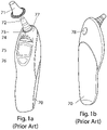
- thermometer 70 A typical prior art infrared thermometer 70 is illustrated in Figs. 1a and 1b .
- the thermometer 70 includes a front end 77, from which an infrared probe 72 projects, for example, with an orientation suitable for placement of the probe 72 in the ear canal.
- a probe cover 71 is positioned to be placed over the probe 72 for eliminating any direct contact between the probe 72 and tissues of the ear canal.
- a power button 76 is provided for powering the circuitry of the thermometer 70.
- a start button 78 is provided to engage the circuitry to perform a temperature measurement, and a display 75 is provided, for example, to indicate a current condition or status of the thermometer 70 and/or the results of a current temperature measurement.
- a probe cover detector 73 is positioned near a base of the probe 72 for detecting that the probe cover 71 has been placed over the probe 72, and may for example interact with the circuitry to permit operation of the thermometer 70 only when installation of the probe cover 71 has been detected.
- a probe cover ejector 74 elevates the front end 77 of the thermometer 70 relative to the probe 72 in order to eject the probe cover 71 from the probe 72.
- the probe cover 71 is not only required to provide a sanitary protection against contamination of the probe by ear wax and other soiling biological compounds, but it must possess other properties for accurate temperature measurement by means of detecting an associated IR signal. Such properties, for example, include a good optical transparency of the probe cover in the spectral range of interest, low directional distortion of optical rays, tight manufacturing tolerances, stability of the optical properties during installation onto the probe, long term stability, and the like.
- Suitable probe covers for IR thermometers are exemplified by U.S. Patent No. 5,088,834 issued to Howe et al. and U.S. Patent No. 5,163,418 issued to Fraden et al. . Most prior art probe covers are formed to surround a longitudinal axis of a thermometer probe.
- a prior art probe cover intended for a medical thermometer includes three portions being disposed along the probe longitudinal axis y (see, e.g., Fig. 2a ):
- Typical materials for fabricating the probe covers are polyethylene, polypropylene, and copolymers of polyethylene and polypropylene.
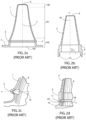
- Fig. 2a shows a prior art unitary probe cover (as taught for example by U.S. Patent No. 5,088,834 ) which is fabricated as a single piece.
- Fig. 2b shows a two-piece probe cover (as taught by U.S. Patent Nos. 4,662,360 , 5,293,862 and 5,179,936, each issued to O'Hara et al. ) where a membrane 6 is welded onto a frustoconical body 4.
- a bottom ring 5 is provided for affixing the probe cover to the probe as part of a proximal portion.
- Probe covers generally have shapes that follow a body of rotation around a longitudinal axis y.
- Probe covers may be attached to the probe or the IR thermometer housing by various mechanisms.
- Fig. 2c once again shows the offset 3, which is an extension of wall 1 of the probe cover in the proximal portion 102.
- the offset 3 engages a nipple 12 that is part of a probe 8 of the IR thermometer when the probe cover is installed onto the probe 8.
- the nipple 12 is disposed along a transverse axis x.
- FIG. 2d illustrates a hook 10 (also illustrated in FIG. 2b ) which is supported by a neck 11.
- the neck 11 is an extension of a ring 5.
- hook 10 engages a retention skirt 49 of a probe cover 9.
- the retention portion 40 of hook 10 is disposed along the transverse axis x.
- Fig. 2e shows a probe cover 4 installed on a probe 9, which includes a retention ring 5 that enables the probe cover 4 to be retained by a frictional force applied to the probe cover 4 along the transverse axis x.
- a probe cover body is formed along the longitudinal axis y, having retention elements formed along the transverse axis x.
- thermometers While having various shapes and methods of retention, often may be interchanged between different types of thermometers. This is undesirable, and may for example cause a mismatch between the type of a membrane 2 (material, thickness and shape) and the thermometer calibration and, as a result, cause unacceptably high errors in temperature measurement. It is important to use only a correct (matching) probe cover with a particular thermometer.
- thermometer a more direct method for preventing usage of a foreign probe cover on a thermometer is desirable.
- the present invention is directed to a probe cover that encourages proper use with a thermometer probe by forming matching elements on a proximal portion of the probe cover to be matched with corresponding elements on a front end of the thermometer in proximity to the probe.
- the matching elements have complementary features to the corresponding elements on the thermometer probe (for example, complementary or interlocking shapes) that form a "key-lock" pair when the probe cover is installed onto the probe. A mismatching of non-corresponding elements makes it impossible either to securely position the probe cover on the probe and/or operate the thermometer.
- the method of matching can be used for any type of a medical thermometer having a probe cover (including, for example, IR and contact thermometers).
- a probe cover for an infrared (IR) thermometer is a sanitary envelope which forms a barrier between the instrument and the patient.
- IR infrared
- several probe covers are described and shown for application to an infrared thermometer used in measuring temperatures in an ear canal of a human or animal.
- the present invention is however equally applicable to probe covers used in a variety of other contexts, for example, including medical contact thermometers that take conductive temperature measurements from a body cavity or surface of a human and veterinary thermometers used for determining the temperature of an animal.
- a distal portion of the probe cover is designed to cover a window of a probe housing through which IR energy is received in order to measure temperature.
- the material for the probe cover's distal portion (that is, for its "optical portion") is preferably selected from the group of polymers which have significant transparency in the spectral range between 3 and 15 ⁇ m. Examples of suitable polymers include polyethylene, polypropylene, and copolymers of polyethylene and polypropylene.
- the thickness of the optical portion of the cover is preferably on the order of 20 micrometers. This thickness provides acceptable IR transmission characteristics, as well as an acceptable mechanical strength.
- a body 1, 2 of the probe cover is substantially symmetrical around a longitudinal axis y.
- a probe cover when installed onto the probe, may be retained by one of many methods known in the art, some of which are described above.
- a preferred embodiment of a probe cover according to the present invention includes middle and distal portions which are not substantially different from those of above-described prior art. It should be noted that the present invention is principally directed to providing additional features in a proximal portion of a probe cover for precisely matching the probe cover to a corresponding thermometer.
- the probe cover of Fig. 3 is a unitary IR probe cover having a membrane 2 adjacent to an IR window 51 of the IR thermometer's probe 8.
- Side wall 1 of the probe cover envelopes sides of the probe 8.
- a circular offset 3 of the probe cover snaps over nipples 12 of the probe 8, thus assuring retention of the probe cover when installed onto the probe 8.
- two or more nipples 12 are opposingly provided on the sides of the probe 8.
- nipples 12 and offset 3 are disposed along a transverse axis x that is normal to the longitudinal axis y.
- a brim 7 is provided and disposed in a direction substantially parallel to the transverse axis x.
- the brim 7 includes a preformed fold 25 that extends upwardly in a direction parallel to the longitudinal axis y.
- the fold 25 may be continuously formed around the longitudinal axis y, or may be broken into two or more segments.
- a front end 17 of the IR thermometer contains at least one pin 23 that enters the fold 25 as the probe cover is installed and seated on the probe.
- two or more pins (23 and 22) are provided on the IR thermometer front end 17 for entering the fold 25.
- the pins 22 and 23 and the fold 25 are not matched (for example, if the probe cover is not intended to be used with the IR thermometer), the mismatch (between the shapes and positions of fold 25 and pins 23 and 22) prevents the probe cover from sitting deeply enough on the probe 8 to be seated. As a result, the offset 3 is not able to engage with the nipples 12, and the probe cover is not effectively retained for use on the probe 8.
- a matching ridge 29 may be formed as part of the IR thermometer front end 17 (see, e.g., Fig. 4a ).
- ridge 29 must have a complimentary shape to fold 25.
- the fold 25 and the corresponding pins 22 and 23, or the ridge 29 are substantially disposed along a matching axis y' that is substantially parallel to the longitudinal axis y and normal to the transverse axis x. Having a ridge 29 that is too wide or is centered at a wrong distance D2 from the longitudinal axis y for a particular probe cover, will prevent such probe cover from being retained on the probe.
- a fold 25 is just one suitable example of a mechanical mating feature according to the present invention.
- Another example is a dip 61 (see, e.g., Fig. 4b ) provided on the brim 7, with a complementary valley 62 provided on the thermometer front end 17.
- the dip 61 is essentially a half fold substantially formed along matching axis y' that is parallel to the longitudinal axis y and perpendicular to the transverse axis x.
- the brim 7 extends laterally outwardly from the matching axis y' rather than forming the second half of the fold as illustrated in the fold 25 of FIG. 4a .
- thermometer a combination of a dip and a fold (or several of them) may be also employed in the probe cover and matched with the corresponding complementary features on the thermometer.
- the mating features such as a fold 25 and dip 61 shown in Figs. 3, 4a and 4b (formed along the matching axis y') and their corresponding mating features 22, 23 and 29 formed on the probe are positioned further from the longitudinal axis y than the retention features such as offset 3 and nipple 12 (see, e.g., respectively corresponding distances D2 and D1 ) .
- the mating features on the IR thermometer may further be aligned with a probe cover ejector.
- the probe cover can be removed (ejected) from the probe by disengaging nipples 12 from offset 3 (see, e.g., Fig. 5b ).
- a disengagement can be accomplished by a simple manual pulling off of the probe cover.
- the disengagement may be assisted by an ejector that is part of the thermometer.
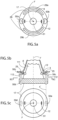
- Fig. 5a depicts a front elevational view of the front end 17 of the thermometer as viewed along longitudinal axis y. No probe cover is installed.
- Fig. 5a illustrates a ridge 29 broken into two segments 29a and 29b. In between these segments, two ejectors 50a and 50b are positioned. The ejectors are normally hidden below the surface of the front end 17, and have shapes and/or locations that are not matching the shape (for example, being wider than) and/or location of the ridge 29.
- Ejection of a probe cover is facilitated, for example, by moving ejectors 50a and 50b upwardly in along axis y'. Because the ejectors 50a, 50b do not match the shapes of the segments 29a, 29b, the ejectors 50a, 50b when operated will not fully enter the fold 25 of the probe cover, and will act therefore to push the probe cover upwardly in a direction parallel to the axis y.
- the IR thermometer may include one or more ejectors. Each ejector is preferably positioned adjacent to one of the nipples 12 of the IR thermometer.
- the ejectors may be configured to serve a dual purpose: providing a matching feature for retaining the probe cover, as well as an ejecting feature.
- the ejectors 50d and 50e when ejectors 50d and 50e are partially retracted (that is, when only portions 50c extend above an upper surface of the front end 17), the ejectors 50d and 50e may serve as ridges for mating with the probe cover fold 25 as illustrated in Fig. 3 .
- the portions 50c provide just enough height to match with the fold 25, and allowing the probe cover 111 to slide sufficiently downward for engaging the offset 3 and nipples 12.
- the portions 50c provide just enough height to match with the fold 25, and allowing the probe cover 111 to slide sufficiently downward for engaging the offset 3 and nipples 12.
- the ejectors 50d, 50e will push the probe cover 111 outwardly and disengage offset 3 from nipple 12.
- at least two ejectors 50d, 50e are positioned near two respective nipples, making two nipple-ejector pairs. Each pair is preferably disposed in opposition along the sides of the probe 8.
- Each ejector is disposed along the axis y' that is parallel to the longitudinal axis y.
- Fig. 5c illustrates a front elevational view of the probe 8 which further shows the positioning of the ejectors 50d, 50e.
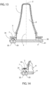
- Fig. 6 illustrates probe cover according to the present invention which includes an outward fold 26 on the brim 7 for mating with valley 27 formed in the front end 17 of the thermometer.
- the fold 26 on the brim 7 extends downwardly along the axis y' that is parallel to the longitudinal axis y.
- a circular brim 19 may be trimmed or relieved with a cut 38 forming a chord or linear segment between two points on the perimeter of the circular brim 19, to facilitate matching or clearance in relation to a pin 14 projecting from the thermometer front end 17. Any number of additional cuts may be added as needed for a particular design.
- Fig. 8 show a probe cover having three cuts 18 made equidistantly around the brim 19. The cuts 38 and 18 are made to match the positions of one or more pins 14, or other complementary features disposed on the thermometer front end 17
- FIG. 9 Another embodiment of the present invention is shown in Fig. 9 .
- one or more holes 20 are formed in the brim 7 of the probe cover along matching axes y' that are parallel with the longitudinal axis y.
- mating pins 13 and 14 are positioned on the front end 17 to match the sizes and locations of holes 20.
- the lateral distance of the pins 13 and 14 from the longitudinal axis y and the angular relationship between the pins 13 and 14 with reference to the longitudinal axis y is matched by the positioning of the holes 20 in the brim 7 of the probe cover when the probe cover is seated on the probe
- conical or similarly-shaped extensions 21 can be formed on brim 7 as depicted in Figs. 10a and 10b .
- they may be preferably formed by use of a thermoforming technology.
- mating pins 22, 23 formed on the front end 17 include conical or similarly-shaped features 22a, 23a for effectively mating with the conical or similarly-shaped extensions 21.
- FIG. 11a Another embodiment of the present invention having yet another mechanical mating feature is shown in Fig. 11a .
- the brim 7 has petals 15 formed by indentations (voids) 16 spaced around a circumference of the brim 7.
- One or more mating pins (for example, the pins 13 and 14) on the thermometer front end 17 allows for the probe cover installation along longitudinal axis y.
- the pins 13 and 14 are positioned to simultaneously enter the voids 16 between the petals to form a "key-lock" arrangement.
- the locking arrangement is shown in more detail in Fig. 11b .
- a two-piece probe cover 55 has a matching feature formed as semi-oval cut-outs 41 in the bottom ring 5 that match corresponding semi-oval fingers 42 of the front end 17 when the probe cover is installed and seated. Any number of other complementary shapes may alternatively be used for the cut-outs and corresponding fingers.
- the cut-outs 41 are provided along the axes y' that are parallel to the longitudinal axis y.
- a non-mechanical matching feature between the probe and probe covers is provided using opto-electronic devices.
- a brim 7 of the probe cover is provided with a reflective layer 30 formed on an underside surface of the brim 7 facing a thermometer body 31.
- the layer 30 may include, for example, an aluminum foil that is welded, glued, sputtered or otherwise deposited on the underside surface brim 7.
- the reflective layer 30 may be a painted layer of selected color.
- the thermometer body 31 carries a light emitter 32 and light detector 33 that together form an opto-coupler.
- the detector 33 is configured to receive a light beam 34 that is transmitted by the light emitter 32 and reflected by the layer 30.
- Detector 33 will respond with a changing electrical signal, thus signaling a detection circuit in the IR thermometer that a suitable probe cover has been properly installed. If the detector 33 detects no reflection, or detects a reflection having a wrong intensity or mismatched spectral characteristics (color), the detection circuit preferably determines that a suitable probe cover has not been installed, and will prevent a temperature measurement from being initiated in the IR thermometer.
- the color of the emitter 32 should be substantially the same to allow for proper reflection of the emitted light. For example, if emitter 32 generates green light and the reflector 30 is also green, then there will be reflection of the emitted light which will then be detected by detector 33. However, if emitter 32 generates green light and the selected color of the reflector 30 is red, there will be a negligible reflection of green light toward detector 33 and the device will indicate a mismatch, i.e., a proper probe cover has not been used. A spectral response of detector 33 should be matched with the spectral response of the emitter 32.
- the reflective layer 35 may be deposited on a side of brim 7 opposite to the underside.
- the light beam 34 will travel through brim 7 on the way to detector 33. This will not change the operation of the opto-coupler 32, 33 and detection circuit, provided that the brim 7 of the probe cover is suitably transparent.
- the embodiment of Fig. 10 could be modified to provide pin features in the brim of the probe cover while providing conical or similarly-shaped extensions in the surface of the front end of the thermometer.
- the reflector and optical circuits could respectively be replaced with an electrical component (for example, a film resistor) and circuits for measuring a selected characteristic of the electrical component (for example, a selected resistance).
Landscapes
- Health & Medical Sciences (AREA)
- Life Sciences & Earth Sciences (AREA)
- Physics & Mathematics (AREA)
- General Physics & Mathematics (AREA)
- Medical Informatics (AREA)
- Molecular Biology (AREA)
- Pathology (AREA)
- Engineering & Computer Science (AREA)
- Biomedical Technology (AREA)
- Heart & Thoracic Surgery (AREA)
- Veterinary Medicine (AREA)
- Biophysics (AREA)
- Surgery (AREA)
- Animal Behavior & Ethology (AREA)
- General Health & Medical Sciences (AREA)
- Public Health (AREA)
- Spectroscopy & Molecular Physics (AREA)
- Otolaryngology (AREA)
- Measuring And Recording Apparatus For Diagnosis (AREA)
- Radiation Pyrometers (AREA)
Claims (8)
- Messfühlerabdeckung zum Abdecken eines Messfühlers eines Thermometers, wobei der Messfühler konfiguriert ist zum Empfangen von Wärmeenergie, die auf eine Temperatur schließen lässt, wobei der Messfühler ein proximales Ende in der Nähe zu einem Gehäuse des Thermometers und ein distales Ende umfasst, wobei die Messfühlerabdeckung Folgendes umfasst:einen Spitzenabschnitt, der konfiguriert ist zum Abdecken des distalen Endes des Messfühlers,einen Basisabschnitt, der konfiguriert ist zum Festhalten der Messfühlerabdeckung an dem proximalen Ende des Messfühlers, undeinen Körperabschnitt, der zwischen dem Spitzenabschnitt und dem Basisabschnitt angeordnet ist, wobei:der Spitzenabschnitt, der Körperabschnitt und der Basisabschnitt aufeinanderfolgend in einer Richtung entlang einer Längsachse der Messfühlerabdeckung angeordnet sind undder Basisabschnitt ein oder mehrere Passmerkmale einschließt, die jeweils dafür konfiguriert sind, ein entsprechendes Merkmal des Thermometergehäuses zum Aufsetzen der Messfühlerabdeckung auf dem Messfühler in Eingriff zu nehmen, wobei die Passmerkmale eine oder mehrere Aussparungen einschließen, die sich in einer Richtung, parallel zu der Längsachse, erstrecken, und wobei das Gehäuse entsprechende Vorsprünge einschließt, die sich in einer Richtung, parallel zu der Längsachse, erstrecken,der Basisabschnitt einen Rand (7) einschließt, der sich in Radialrichtung weg von der Längsachse der Messfühlerabdeckung erstreckt, die eine oder die mehreren Aussparungen schließen eine oder mehrere konische oder ähnlich geformte Erweiterungen (21) ein, die an dem Rand (7) geformt sind, und der eine oder die mehreren Vorsprünge schließen einen oder mehrere Verbindungsstifte (22, 23) ein, die konische oder ähnlich geformte Merkmale (22a, 23a) zum wirksamen Verbinden mit den Erweiterungen aufweisen,das Thermometer einen oder mehrere Ausstoßer (50a, 50b) aufweist, die in dem Gehäuse angeordnet sind und beweglich betätigt werden können, um sich aus dem Gehäuse auszufahren und die untere Fläche des Basisabschnitts zum Ausstoßen der Messfühlerabdeckung von dem Messfühler in Eingriff zu nehmen,die Messfühlerabdeckung dadurch gekennzeichnet ist, dass jeder von dem einen oder den mehreren Ausstoßern konfiguriert ist als ein entsprechendes Merkmal des Gehäuses zum Verbinden mit einem entsprechenden von dem einen oder den mehreren Passmerkmalen der Messfühlerabdeckung.
- Messfühlerabdeckung nach Anspruch 1, wobei:
der Basisabschnitt ferner mindestens einen Vorsprung (3) einschließt, der sich seitlich weg von der Mittelachse erstreckt, zum In-Eingriff-Nehmen eines Positionierungselements (12) des Messfühlers, um die Abdeckung an einer Aufsatzposition an dem Messfühler zu positionieren, wobei eine seitliche Entfernung von einem seitlichsten Abschnitt jedes Passmerkmals zu der Längsachse größer ist als eine seitliche Entfernung von einem seitlichsten Abschnitt des mindestens einen Vorsprungs zu der Längsachse. - Messfühlerabdeckung nach Anspruch 1, wobei:
der Basisabschnitt ferner mindestens einen Vorsprung (3) einschließt, der sich seitlich weg von der Mittelachse erstreckt, zum In-Eingriff-Nehmen eines Positionierungselements (12) des Messfühlers, um die Abdeckung an einer Aufsatzposition an dem Messfühler zu positionieren. - Messfühlerabdeckung nach Anspruch 1, wobei:mindestens ein Vorsprung (3) des Körperabschnitts, der sich seitlich weg von der Mittelachse erstreckt, dafür konfiguriert ist, einen Nippel (12) des Messfühlers aufzunehmen, undeiner von dem einen oder den mehreren Ausstoßern (50a, 50b) betätigt werden kann, um sich zu einer Position, angrenzend an den Nippel des Messfühlers, auszufahren.
- Messfühlerabdeckung nach Anspruch 4, wobei mindestens zwei Ausstoßer (50d, 50e) nahe zwei jeweiligen Nippeln angeordnet sind, was zwei Nippel-Ausstoßer-Paare ergibt.
- Messfühlerabdeckung nach Anspruch 5, wobei jedes Paar vorzugsweise gegenüberliegend entlang der Seiten des Messfühlers 8 angeordnet ist.
- Messfühlerabdeckung nach Anspruch 6, wobei jeder Ausstoßer entlang der Achse y' angeordnet ist, die parallel zu der Längsachse y ist.
- Thermometer, das eine Messfühlerabdeckung nach einem der Ansprüche 1 bis 7 aufweist.
Applications Claiming Priority (2)
| Application Number | Priority Date | Filing Date | Title |
|---|---|---|---|
| US20364108P | 2008-12-29 | 2008-12-29 | |
| PCT/US2009/069528 WO2010078219A1 (en) | 2008-12-29 | 2009-12-24 | Probe cover with matching feature for a medical thermometer |
Publications (3)
| Publication Number | Publication Date |
|---|---|
| EP2373963A1 EP2373963A1 (de) | 2011-10-12 |
| EP2373963A4 EP2373963A4 (de) | 2017-12-20 |
| EP2373963B1 true EP2373963B1 (de) | 2023-03-01 |
Family
ID=42310173
Family Applications (1)
| Application Number | Title | Priority Date | Filing Date |
|---|---|---|---|
| EP09837059.6A Active EP2373963B1 (de) | 2008-12-29 | 2009-12-24 | Sondenüberzug mit passungsmerkmal für ein medizinisches thermometer |
Country Status (9)
| Country | Link |
|---|---|
| US (3) | US8882347B2 (de) |
| EP (1) | EP2373963B1 (de) |
| JP (1) | JP5431500B2 (de) |
| KR (2) | KR101621120B1 (de) |
| CN (2) | CN103637776B (de) |
| CA (2) | CA2750838C (de) |
| MX (1) | MX2011006982A (de) |
| TW (1) | TWI479135B (de) |
| WO (1) | WO2010078219A1 (de) |
Families Citing this family (30)
| Publication number | Priority date | Publication date | Assignee | Title |
|---|---|---|---|---|
| US20070248141A1 (en) * | 2006-04-21 | 2007-10-25 | Sherwood Services Ag | Infrared thermometer and probe cover thereof |
| TW200921063A (en) * | 2007-11-09 | 2009-05-16 | Actherm Inc | Probe cover for ear thermometer and manufacturing method thereof |
| USD685482S1 (en) | 2009-04-09 | 2013-07-02 | Welch Allyn, Inc. | Cover for a probe or the like |
| US12492949B2 (en) * | 2009-04-09 | 2025-12-09 | Welch Allyn, Inc. | IR thermometry probe cover |
| USD787683S1 (en) | 2009-04-09 | 2017-05-23 | Welch Allyn, Inc. | Cover for a probe |
| US8231271B2 (en) | 2009-04-09 | 2012-07-31 | Welch Allyn, Inc. | IR thermometry probe cover |
| US8876373B2 (en) | 2009-04-09 | 2014-11-04 | Welch Allyn, Inc. | IR thermometry probe cover |
| US8186876B2 (en) * | 2009-04-20 | 2012-05-29 | Welch Allyn, Inc. | Calibrated assembly for IR thermometer apparatus |
| KR101668905B1 (ko) * | 2009-10-05 | 2016-10-24 | 카즈 유럽 에스에이 | 귀 체온계를 위한 다중 부위용 어태치먼트 |
| US8996096B2 (en) | 2011-07-19 | 2015-03-31 | Welch Allyn, Inc. | Systems and methods for determining patient temperature |
| US8251578B1 (en) * | 2011-09-21 | 2012-08-28 | Polygreen Germany Gmbh | Infrared temperature sensing device with projecting function |
| US8292500B1 (en) * | 2011-09-30 | 2012-10-23 | Tyco Healthcare Group Lp | IR sensor for electronic thermometer |
| US8949065B2 (en) | 2011-09-30 | 2015-02-03 | Covidien Lp | Capacitive sensor for thermometer probe |
| US8651736B2 (en) * | 2012-02-03 | 2014-02-18 | Welch Allyn, Inc. | Probe cover container identification |
| US9357930B2 (en) * | 2012-03-19 | 2016-06-07 | Welch Allyn, Inc. | Temperature measurement system |
| TWM453480U (zh) * | 2012-10-11 | 2013-05-21 | Avita Corp | 體溫量測裝置 |
| DE102012223691A1 (de) * | 2012-12-19 | 2014-06-26 | Heine Optotechnik Gmbh & Co Kg | Otoskop mit abwerfbarem Ohrtrichter |
| HK1219857A1 (zh) | 2013-02-04 | 2017-04-21 | Helen Of Troy Limited | 耳镜 |
| WO2014117956A2 (en) | 2013-02-04 | 2014-08-07 | Helen Of Troy Limited | Ear inspection device and method of determining a condition of a subject's ear |
| SG10201706407XA (en) | 2013-02-04 | 2017-09-28 | Helen Of Troy Ltd | Otoscope |
| MX366017B (es) | 2013-02-04 | 2019-06-24 | Helen Of Troy Ltd | Método para identificar objetos en el oído de un sujeto. |
| USD872859S1 (en) * | 2017-03-09 | 2020-01-14 | Pieter Van Weenen & Co. Gmbh | Part of an apparatus for medical and laboratory diagnosis |
| TWI672122B (zh) * | 2018-07-09 | 2019-09-21 | 熱映光電股份有限公司 | 耳溫槍用探頭套 |
| CN110736553B (zh) * | 2018-07-18 | 2021-06-01 | 热映光电股份有限公司 | 耳温枪用探头套 |
| USD913817S1 (en) * | 2019-05-17 | 2021-03-23 | Famidoc Technology Co., Ltd. | Infrared thermometer |
| CN110108387B (zh) * | 2019-05-25 | 2020-11-10 | 深圳市奥极医疗科技有限公司 | 探头结构及体温计 |
| USD916603S1 (en) * | 2019-05-30 | 2021-04-20 | Chiat Koo Lim | Infrared forehead thermometer |
| CN112729549B (zh) | 2019-10-14 | 2021-10-22 | 百略医学科技股份有限公司 | 具耳套弹出装置的耳温枪 |
| US11950937B2 (en) * | 2021-04-07 | 2024-04-09 | Radiant Innovation Inc. | Probe cover for ear thermometer and grouping method of the same |
| CN115900963A (zh) * | 2021-09-28 | 2023-04-04 | 深圳迈瑞生物医疗电子股份有限公司 | 应用于耳温测量装置的护套及耳温测量设备 |
Family Cites Families (32)
| Publication number | Priority date | Publication date | Assignee | Title |
|---|---|---|---|---|
| US4159766A (en) | 1976-11-01 | 1979-07-03 | Diatek, Inc. | Cover for temperature sensing probe |
| US5179936A (en) | 1984-10-23 | 1993-01-19 | Intelligent Medical Systems, Inc. | Disposable speculum with membrane bonding ring |
| US4662360A (en) | 1984-10-23 | 1987-05-05 | Intelligent Medical Systems, Inc. | Disposable speculum |
| US5163418A (en) | 1989-09-19 | 1992-11-17 | Thermoscan Inc. | Speculum cover |
| US5088834A (en) | 1990-08-24 | 1992-02-18 | Thermoscan Inc. | Unitary probe cover |
| US5411032A (en) * | 1993-06-18 | 1995-05-02 | Infra-Temp Inc. | Electronic thermometer probe cover |
| US6309671B1 (en) * | 1995-04-14 | 2001-10-30 | Inhale Therapeutic Systems | Stable glassy state powder formulations |
| TW410272B (en) | 1996-05-07 | 2000-11-01 | Thermoscan Lnc | Enhanced protective lens cover |
| JP2000510721A (ja) * | 1996-05-07 | 2000-08-22 | サーモスキャン,インコーポレーテッド | 赤外線温度計用の保護カバー |
| DE19724054C2 (de) * | 1997-06-07 | 2002-09-12 | Braun Gmbh | Strahlungsthermometer und Schutzkappe dafür |
| JP3514138B2 (ja) * | 1998-09-29 | 2004-03-31 | テルモ株式会社 | プローブカバー取り外し機構および耳式体温計 |
| ATE362614T1 (de) * | 1998-10-20 | 2007-06-15 | Omron Healthcare Co Ltd | Infrarotthermometer |
| JP2000131146A (ja) * | 1998-10-28 | 2000-05-12 | Omron Corp | 電子温度計 |
| US6461037B1 (en) | 1999-02-28 | 2002-10-08 | Alaris Medical Systems, Inc. | Thermometer probe for use with disposable probe cover |
| US6139182A (en) * | 1999-03-01 | 2000-10-31 | Thermoscan, Inc | Enhanced protective cover for use in an IR thermometer |
| DE19929503B4 (de) * | 1999-06-28 | 2008-06-26 | Braun Gmbh | IR-Thermometer für unterschiedliche Messorte |
| US6254271B1 (en) | 1999-06-29 | 2001-07-03 | Oriental System Technology Inc. | Probe cover of tympanic thermometer |
| JP2001078967A (ja) * | 1999-09-09 | 2001-03-27 | Kazuhito Sakano | プローブカバー及びそれを装着する耳式体温計のプローブ並びにそれらの着脱構造 |
| US6619837B2 (en) * | 2001-05-17 | 2003-09-16 | Sherwood Services Ag | Probe cover with lubrication well |
| JP3945189B2 (ja) * | 2001-06-01 | 2007-07-18 | オムロンヘルスケア株式会社 | 赤外線体温計 |
| US6850789B2 (en) | 2002-07-29 | 2005-02-01 | Welch Allyn, Inc. | Combination SPO2/temperature measuring apparatus |
| TW538238B (en) * | 2002-09-16 | 2003-06-21 | Oriental System Technology Inc | Probe cover and assembly of ear clinical thermometer |
| ES2345678T3 (es) * | 2003-01-06 | 2010-09-29 | Covidien Ag | Cubierta de sonda para un termometro timpanico. |
| US7354194B2 (en) * | 2003-01-06 | 2008-04-08 | Covidien Ag | Tympanic thermometer probe cover with film support mechanism |
| US7354399B2 (en) * | 2003-07-28 | 2008-04-08 | Welch Allyn, Inc. | Otoscopic tip element and related method of use |
| US7815367B2 (en) * | 2004-11-16 | 2010-10-19 | Welch Allyn, Inc. | Multi-site infrared thermometer |
| US7572056B2 (en) * | 2004-11-16 | 2009-08-11 | Welch Allyn, Inc. | Probe cover for thermometry apparatus |
| JP5053674B2 (ja) | 2007-03-26 | 2012-10-17 | テルモ株式会社 | 耳式体温計 |
| US8657491B2 (en) * | 2007-11-09 | 2014-02-25 | Actherm Inc. | Detachable probe cover for ear thermometer and manufacturing method thereof |
| TWI340822B (en) * | 2007-11-15 | 2011-04-21 | Actherm Inc | Probe cover for an ear thermometer, manufacturing method thereof |
| SG157973A1 (en) * | 2008-06-18 | 2010-01-29 | Indian Inst Technology Bombay | Method for growing monocrystalline diamonds |
| CA2795703C (en) * | 2010-04-05 | 2019-11-26 | Helen Of Troy Limited | Insertion detector for a medical probe |
-
2009
- 2009-12-24 EP EP09837059.6A patent/EP2373963B1/de active Active
- 2009-12-24 JP JP2011543697A patent/JP5431500B2/ja active Active
- 2009-12-24 KR KR1020117017672A patent/KR101621120B1/ko not_active Expired - Fee Related
- 2009-12-24 CA CA2750838A patent/CA2750838C/en active Active
- 2009-12-24 MX MX2011006982A patent/MX2011006982A/es active IP Right Grant
- 2009-12-24 KR KR1020157031484A patent/KR101672667B1/ko active Active
- 2009-12-24 CN CN201310562448.8A patent/CN103637776B/zh active Active
- 2009-12-24 WO PCT/US2009/069528 patent/WO2010078219A1/en not_active Ceased
- 2009-12-24 CA CA2910295A patent/CA2910295C/en active Active
- 2009-12-24 CN CN200980153128.9A patent/CN102282448B/zh active Active
- 2009-12-24 US US12/675,877 patent/US8882347B2/en active Active
- 2009-12-28 TW TW098145296A patent/TWI479135B/zh active
-
2013
- 2013-01-23 US US13/747,918 patent/US9285276B2/en active Active
-
2016
- 2016-03-14 US US15/069,412 patent/US9854978B2/en not_active Expired - Fee Related
Also Published As
| Publication number | Publication date |
|---|---|
| CN103637776B (zh) | 2015-08-05 |
| TWI479135B (zh) | 2015-04-01 |
| JP2012514200A (ja) | 2012-06-21 |
| US20170020397A1 (en) | 2017-01-26 |
| EP2373963A1 (de) | 2011-10-12 |
| CA2910295C (en) | 2018-03-06 |
| MX2011006982A (es) | 2011-08-15 |
| HK1190899A1 (en) | 2014-07-18 |
| US8882347B2 (en) | 2014-11-11 |
| CN103637776A (zh) | 2014-03-19 |
| TW201030326A (en) | 2010-08-16 |
| KR101672667B1 (ko) | 2016-11-03 |
| US20110134962A1 (en) | 2011-06-09 |
| KR20110099784A (ko) | 2011-09-08 |
| HK1164998A1 (zh) | 2012-09-28 |
| EP2373963A4 (de) | 2017-12-20 |
| CN102282448A (zh) | 2011-12-14 |
| KR101621120B1 (ko) | 2016-05-13 |
| CN102282448B (zh) | 2015-12-09 |
| US9285276B2 (en) | 2016-03-15 |
| WO2010078219A1 (en) | 2010-07-08 |
| JP5431500B2 (ja) | 2014-03-05 |
| US20130128926A1 (en) | 2013-05-23 |
| CA2750838C (en) | 2016-11-22 |
| KR20150129059A (ko) | 2015-11-18 |
| US9854978B2 (en) | 2018-01-02 |
| CA2750838A1 (en) | 2010-07-08 |
| CA2910295A1 (en) | 2010-07-08 |
Similar Documents
| Publication | Publication Date | Title |
|---|---|---|
| EP2373963B1 (de) | Sondenüberzug mit passungsmerkmal für ein medizinisches thermometer | |
| TWI495859B (zh) | 用於耳溫計之多點附接技術 | |
| USRE43745E1 (en) | Tympanic thermometer probe cover with film support mechanism | |
| US9591971B2 (en) | Insertion detector for medical probe | |
| EP1860413B1 (de) | Sondenabdeckung für Trommelfellthermometer | |
| US6152596A (en) | Protective cover for infrared thermometer | |
| US20060120432A1 (en) | Tympanic thermometer with ejection mechanism | |
| HK1190899B (en) | Probe cover with matching feature for a medical thermometer | |
| HK1164998B (en) | Probe cover with matching feature for a medical thermometer | |
| MXPA05007261A (es) | Termometro timpanico con mecanismo de expulsion. | |
| HK1104850A (en) | Tympanic thermometer probe cover with film support mechanism | |
| HK1172390B (en) | Multi-site attachments for ear thermometers |
Legal Events
| Date | Code | Title | Description |
|---|---|---|---|
| PUAI | Public reference made under article 153(3) epc to a published international application that has entered the european phase |
Free format text: ORIGINAL CODE: 0009012 |
|
| 17P | Request for examination filed |
Effective date: 20110704 |
|
| AK | Designated contracting states |
Kind code of ref document: A1 Designated state(s): AT BE BG CH CY CZ DE DK EE ES FI FR GB GR HR HU IE IS IT LI LT LU LV MC MK MT NL NO PL PT RO SE SI SK SM TR |
|
| DAX | Request for extension of the european patent (deleted) | ||
| RA4 | Supplementary search report drawn up and despatched (corrected) |
Effective date: 20171117 |
|
| RIC1 | Information provided on ipc code assigned before grant |
Ipc: G01K 1/08 20060101AFI20171113BHEP |
|
| STAA | Information on the status of an ep patent application or granted ep patent |
Free format text: STATUS: EXAMINATION IS IN PROGRESS |
|
| 17Q | First examination report despatched |
Effective date: 20210414 |
|
| GRAP | Despatch of communication of intention to grant a patent |
Free format text: ORIGINAL CODE: EPIDOSNIGR1 |
|
| STAA | Information on the status of an ep patent application or granted ep patent |
Free format text: STATUS: GRANT OF PATENT IS INTENDED |
|
| INTG | Intention to grant announced |
Effective date: 20221024 |
|
| GRAS | Grant fee paid |
Free format text: ORIGINAL CODE: EPIDOSNIGR3 |
|
| GRAA | (expected) grant |
Free format text: ORIGINAL CODE: 0009210 |
|
| STAA | Information on the status of an ep patent application or granted ep patent |
Free format text: STATUS: THE PATENT HAS BEEN GRANTED |
|
| AK | Designated contracting states |
Kind code of ref document: B1 Designated state(s): AT BE BG CH CY CZ DE DK EE ES FI FR GB GR HR HU IE IS IT LI LT LU LV MC MK MT NL NO PL PT RO SE SI SK SM TR |
|
| REG | Reference to a national code |
Ref country code: GB Ref legal event code: FG4D |
|
| REG | Reference to a national code |
Ref country code: CH Ref legal event code: EP Ref country code: AT Ref legal event code: REF Ref document number: 1551277 Country of ref document: AT Kind code of ref document: T Effective date: 20230315 |
|
| REG | Reference to a national code |
Ref country code: DE Ref legal event code: R096 Ref document number: 602009064765 Country of ref document: DE |
|
| REG | Reference to a national code |
Ref country code: IE Ref legal event code: FG4D |
|
| REG | Reference to a national code |
Ref country code: LT Ref legal event code: MG9D |
|
| PG25 | Lapsed in a contracting state [announced via postgrant information from national office to epo] |
Ref country code: NO Free format text: LAPSE BECAUSE OF FAILURE TO SUBMIT A TRANSLATION OF THE DESCRIPTION OR TO PAY THE FEE WITHIN THE PRESCRIBED TIME-LIMIT Effective date: 20230601 Ref country code: LV Free format text: LAPSE BECAUSE OF FAILURE TO SUBMIT A TRANSLATION OF THE DESCRIPTION OR TO PAY THE FEE WITHIN THE PRESCRIBED TIME-LIMIT Effective date: 20230301 Ref country code: LT Free format text: LAPSE BECAUSE OF FAILURE TO SUBMIT A TRANSLATION OF THE DESCRIPTION OR TO PAY THE FEE WITHIN THE PRESCRIBED TIME-LIMIT Effective date: 20230301 Ref country code: HR Free format text: LAPSE BECAUSE OF FAILURE TO SUBMIT A TRANSLATION OF THE DESCRIPTION OR TO PAY THE FEE WITHIN THE PRESCRIBED TIME-LIMIT Effective date: 20230301 Ref country code: ES Free format text: LAPSE BECAUSE OF FAILURE TO SUBMIT A TRANSLATION OF THE DESCRIPTION OR TO PAY THE FEE WITHIN THE PRESCRIBED TIME-LIMIT Effective date: 20230301 |
|
| REG | Reference to a national code |
Ref country code: AT Ref legal event code: MK05 Ref document number: 1551277 Country of ref document: AT Kind code of ref document: T Effective date: 20230301 |
|
| PG25 | Lapsed in a contracting state [announced via postgrant information from national office to epo] |
Ref country code: SE Free format text: LAPSE BECAUSE OF FAILURE TO SUBMIT A TRANSLATION OF THE DESCRIPTION OR TO PAY THE FEE WITHIN THE PRESCRIBED TIME-LIMIT Effective date: 20230301 Ref country code: PL Free format text: LAPSE BECAUSE OF FAILURE TO SUBMIT A TRANSLATION OF THE DESCRIPTION OR TO PAY THE FEE WITHIN THE PRESCRIBED TIME-LIMIT Effective date: 20230301 Ref country code: NL Free format text: LAPSE BECAUSE OF FAILURE TO SUBMIT A TRANSLATION OF THE DESCRIPTION OR TO PAY THE FEE WITHIN THE PRESCRIBED TIME-LIMIT Effective date: 20230301 Ref country code: GR Free format text: LAPSE BECAUSE OF FAILURE TO SUBMIT A TRANSLATION OF THE DESCRIPTION OR TO PAY THE FEE WITHIN THE PRESCRIBED TIME-LIMIT Effective date: 20230602 Ref country code: FI Free format text: LAPSE BECAUSE OF FAILURE TO SUBMIT A TRANSLATION OF THE DESCRIPTION OR TO PAY THE FEE WITHIN THE PRESCRIBED TIME-LIMIT Effective date: 20230301 |
|
| PG25 | Lapsed in a contracting state [announced via postgrant information from national office to epo] |
Ref country code: SM Free format text: LAPSE BECAUSE OF FAILURE TO SUBMIT A TRANSLATION OF THE DESCRIPTION OR TO PAY THE FEE WITHIN THE PRESCRIBED TIME-LIMIT Effective date: 20230301 Ref country code: RO Free format text: LAPSE BECAUSE OF FAILURE TO SUBMIT A TRANSLATION OF THE DESCRIPTION OR TO PAY THE FEE WITHIN THE PRESCRIBED TIME-LIMIT Effective date: 20230301 Ref country code: PT Free format text: LAPSE BECAUSE OF FAILURE TO SUBMIT A TRANSLATION OF THE DESCRIPTION OR TO PAY THE FEE WITHIN THE PRESCRIBED TIME-LIMIT Effective date: 20230703 Ref country code: EE Free format text: LAPSE BECAUSE OF FAILURE TO SUBMIT A TRANSLATION OF THE DESCRIPTION OR TO PAY THE FEE WITHIN THE PRESCRIBED TIME-LIMIT Effective date: 20230301 Ref country code: CZ Free format text: LAPSE BECAUSE OF FAILURE TO SUBMIT A TRANSLATION OF THE DESCRIPTION OR TO PAY THE FEE WITHIN THE PRESCRIBED TIME-LIMIT Effective date: 20230301 Ref country code: AT Free format text: LAPSE BECAUSE OF FAILURE TO SUBMIT A TRANSLATION OF THE DESCRIPTION OR TO PAY THE FEE WITHIN THE PRESCRIBED TIME-LIMIT Effective date: 20230301 |
|
| PG25 | Lapsed in a contracting state [announced via postgrant information from national office to epo] |
Ref country code: SK Free format text: LAPSE BECAUSE OF FAILURE TO SUBMIT A TRANSLATION OF THE DESCRIPTION OR TO PAY THE FEE WITHIN THE PRESCRIBED TIME-LIMIT Effective date: 20230301 Ref country code: IS Free format text: LAPSE BECAUSE OF FAILURE TO SUBMIT A TRANSLATION OF THE DESCRIPTION OR TO PAY THE FEE WITHIN THE PRESCRIBED TIME-LIMIT Effective date: 20230701 |
|
| REG | Reference to a national code |
Ref country code: DE Ref legal event code: R097 Ref document number: 602009064765 Country of ref document: DE |
|
| PLBE | No opposition filed within time limit |
Free format text: ORIGINAL CODE: 0009261 |
|
| STAA | Information on the status of an ep patent application or granted ep patent |
Free format text: STATUS: NO OPPOSITION FILED WITHIN TIME LIMIT |
|
| PG25 | Lapsed in a contracting state [announced via postgrant information from national office to epo] |
Ref country code: SI Free format text: LAPSE BECAUSE OF FAILURE TO SUBMIT A TRANSLATION OF THE DESCRIPTION OR TO PAY THE FEE WITHIN THE PRESCRIBED TIME-LIMIT Effective date: 20230301 Ref country code: DK Free format text: LAPSE BECAUSE OF FAILURE TO SUBMIT A TRANSLATION OF THE DESCRIPTION OR TO PAY THE FEE WITHIN THE PRESCRIBED TIME-LIMIT Effective date: 20230301 |
|
| 26N | No opposition filed |
Effective date: 20231204 |
|
| PG25 | Lapsed in a contracting state [announced via postgrant information from national office to epo] |
Ref country code: IT Free format text: LAPSE BECAUSE OF FAILURE TO SUBMIT A TRANSLATION OF THE DESCRIPTION OR TO PAY THE FEE WITHIN THE PRESCRIBED TIME-LIMIT Effective date: 20230301 |
|
| REG | Reference to a national code |
Ref country code: CH Ref legal event code: PL |
|
| PG25 | Lapsed in a contracting state [announced via postgrant information from national office to epo] |
Ref country code: LU Free format text: LAPSE BECAUSE OF NON-PAYMENT OF DUE FEES Effective date: 20231224 |
|
| PG25 | Lapsed in a contracting state [announced via postgrant information from national office to epo] |
Ref country code: MC Free format text: LAPSE BECAUSE OF FAILURE TO SUBMIT A TRANSLATION OF THE DESCRIPTION OR TO PAY THE FEE WITHIN THE PRESCRIBED TIME-LIMIT Effective date: 20230301 |
|
| REG | Reference to a national code |
Ref country code: BE Ref legal event code: MM Effective date: 20231231 |
|
| PG25 | Lapsed in a contracting state [announced via postgrant information from national office to epo] |
Ref country code: MC Free format text: LAPSE BECAUSE OF FAILURE TO SUBMIT A TRANSLATION OF THE DESCRIPTION OR TO PAY THE FEE WITHIN THE PRESCRIBED TIME-LIMIT Effective date: 20230301 Ref country code: LU Free format text: LAPSE BECAUSE OF NON-PAYMENT OF DUE FEES Effective date: 20231224 |
|
| REG | Reference to a national code |
Ref country code: IE Ref legal event code: MM4A |
|
| PG25 | Lapsed in a contracting state [announced via postgrant information from national office to epo] |
Ref country code: IE Free format text: LAPSE BECAUSE OF NON-PAYMENT OF DUE FEES Effective date: 20231224 |
|
| PG25 | Lapsed in a contracting state [announced via postgrant information from national office to epo] |
Ref country code: BE Free format text: LAPSE BECAUSE OF NON-PAYMENT OF DUE FEES Effective date: 20231231 |
|
| PG25 | Lapsed in a contracting state [announced via postgrant information from national office to epo] |
Ref country code: FR Free format text: LAPSE BECAUSE OF NON-PAYMENT OF DUE FEES Effective date: 20231231 |
|
| PG25 | Lapsed in a contracting state [announced via postgrant information from national office to epo] |
Ref country code: CH Free format text: LAPSE BECAUSE OF NON-PAYMENT OF DUE FEES Effective date: 20231231 |
|
| PG25 | Lapsed in a contracting state [announced via postgrant information from national office to epo] |
Ref country code: IE Free format text: LAPSE BECAUSE OF NON-PAYMENT OF DUE FEES Effective date: 20231224 Ref country code: FR Free format text: LAPSE BECAUSE OF NON-PAYMENT OF DUE FEES Effective date: 20231231 Ref country code: CH Free format text: LAPSE BECAUSE OF NON-PAYMENT OF DUE FEES Effective date: 20231231 Ref country code: BE Free format text: LAPSE BECAUSE OF NON-PAYMENT OF DUE FEES Effective date: 20231231 |
|
| PG25 | Lapsed in a contracting state [announced via postgrant information from national office to epo] |
Ref country code: BG Free format text: LAPSE BECAUSE OF FAILURE TO SUBMIT A TRANSLATION OF THE DESCRIPTION OR TO PAY THE FEE WITHIN THE PRESCRIBED TIME-LIMIT Effective date: 20230301 |
|
| PG25 | Lapsed in a contracting state [announced via postgrant information from national office to epo] |
Ref country code: BG Free format text: LAPSE BECAUSE OF FAILURE TO SUBMIT A TRANSLATION OF THE DESCRIPTION OR TO PAY THE FEE WITHIN THE PRESCRIBED TIME-LIMIT Effective date: 20230301 |
|
| PG25 | Lapsed in a contracting state [announced via postgrant information from national office to epo] |
Ref country code: HU Free format text: LAPSE BECAUSE OF FAILURE TO SUBMIT A TRANSLATION OF THE DESCRIPTION OR TO PAY THE FEE WITHIN THE PRESCRIBED TIME-LIMIT; INVALID AB INITIO Effective date: 20091224 |
|
| PG25 | Lapsed in a contracting state [announced via postgrant information from national office to epo] |
Ref country code: CY Free format text: LAPSE BECAUSE OF FAILURE TO SUBMIT A TRANSLATION OF THE DESCRIPTION OR TO PAY THE FEE WITHIN THE PRESCRIBED TIME-LIMIT; INVALID AB INITIO Effective date: 20091224 |
|
| PG25 | Lapsed in a contracting state [announced via postgrant information from national office to epo] |
Ref country code: TR Free format text: LAPSE BECAUSE OF FAILURE TO SUBMIT A TRANSLATION OF THE DESCRIPTION OR TO PAY THE FEE WITHIN THE PRESCRIBED TIME-LIMIT Effective date: 20230301 |
|
| PGFP | Annual fee paid to national office [announced via postgrant information from national office to epo] |
Ref country code: DE Payment date: 20250930 Year of fee payment: 17 |
|
| PGFP | Annual fee paid to national office [announced via postgrant information from national office to epo] |
Ref country code: GB Payment date: 20251001 Year of fee payment: 17 |