EP2373238B1 - Rod reducer apparatus for spinal corrective surgery - Google Patents
Rod reducer apparatus for spinal corrective surgery Download PDFInfo
- Publication number
- EP2373238B1 EP2373238B1 EP09775382.6A EP09775382A EP2373238B1 EP 2373238 B1 EP2373238 B1 EP 2373238B1 EP 09775382 A EP09775382 A EP 09775382A EP 2373238 B1 EP2373238 B1 EP 2373238B1
- Authority
- EP
- European Patent Office
- Prior art keywords
- threaded member
- spinal rod
- rod
- tool
- threaded
- Prior art date
- Legal status (The legal status is an assumption and is not a legal conclusion. Google has not performed a legal analysis and makes no representation as to the accuracy of the status listed.)
- Active
Links
- 239000003638 chemical reducing agent Substances 0.000 title description 37
- 238000001356 surgical procedure Methods 0.000 title description 3
- 230000009467 reduction Effects 0.000 claims description 20
- 230000000712 assembly Effects 0.000 claims description 12
- 238000000429 assembly Methods 0.000 claims description 12
- 230000003247 decreasing effect Effects 0.000 claims description 2
- 230000013011 mating Effects 0.000 claims 1
- 238000000034 method Methods 0.000 description 9
- 210000000078 claw Anatomy 0.000 description 4
- 230000008878 coupling Effects 0.000 description 4
- 238000010168 coupling process Methods 0.000 description 4
- 238000005859 coupling reaction Methods 0.000 description 4
- 239000004696 Poly ether ether ketone Substances 0.000 description 3
- 229920002530 polyetherether ketone Polymers 0.000 description 3
- RTAQQCXQSZGOHL-UHFFFAOYSA-N Titanium Chemical compound [Ti] RTAQQCXQSZGOHL-UHFFFAOYSA-N 0.000 description 2
- 238000010276 construction Methods 0.000 description 2
- 238000002513 implantation Methods 0.000 description 2
- 239000010936 titanium Substances 0.000 description 2
- 229910052719 titanium Inorganic materials 0.000 description 2
- 206010058907 Spinal deformity Diseases 0.000 description 1
- 238000005452 bending Methods 0.000 description 1
- 239000000560 biocompatible material Substances 0.000 description 1
- 229920000249 biocompatible polymer Polymers 0.000 description 1
- 230000001419 dependent effect Effects 0.000 description 1
- 239000007943 implant Substances 0.000 description 1
- 230000008676 import Effects 0.000 description 1
- 238000011065 in-situ storage Methods 0.000 description 1
- 229910052751 metal Inorganic materials 0.000 description 1
- 239000002184 metal Substances 0.000 description 1
- 230000000399 orthopedic effect Effects 0.000 description 1
- 239000002861 polymer material Substances 0.000 description 1
- 210000004872 soft tissue Anatomy 0.000 description 1
- 230000006641 stabilisation Effects 0.000 description 1
- 238000011105 stabilization Methods 0.000 description 1
- 229910001220 stainless steel Inorganic materials 0.000 description 1
- 239000010935 stainless steel Substances 0.000 description 1
- 239000013585 weight reducing agent Substances 0.000 description 1
Images


Classifications
-
- A—HUMAN NECESSITIES
- A61—MEDICAL OR VETERINARY SCIENCE; HYGIENE
- A61B—DIAGNOSIS; SURGERY; IDENTIFICATION
- A61B17/00—Surgical instruments, devices or methods, e.g. tourniquets
- A61B17/56—Surgical instruments or methods for treatment of bones or joints; Devices specially adapted therefor
- A61B17/58—Surgical instruments or methods for treatment of bones or joints; Devices specially adapted therefor for osteosynthesis, e.g. bone plates, screws, setting implements or the like
- A61B17/68—Internal fixation devices, including fasteners and spinal fixators, even if a part thereof projects from the skin
- A61B17/70—Spinal positioners or stabilisers ; Bone stabilisers comprising fluid filler in an implant
- A61B17/7074—Tools specially adapted for spinal fixation operations other than for bone removal or filler handling
- A61B17/7083—Tools for guidance or insertion of tethers, rod-to-anchor connectors, rod-to-rod connectors, or longitudinal elements
- A61B17/7086—Rod reducers, i.e. devices providing a mechanical advantage to allow a user to force a rod into or onto an anchor head other than by means of a rod-to-bone anchor locking element; rod removers
-
- A—HUMAN NECESSITIES
- A61—MEDICAL OR VETERINARY SCIENCE; HYGIENE
- A61B—DIAGNOSIS; SURGERY; IDENTIFICATION
- A61B17/00—Surgical instruments, devices or methods, e.g. tourniquets
- A61B17/56—Surgical instruments or methods for treatment of bones or joints; Devices specially adapted therefor
- A61B17/58—Surgical instruments or methods for treatment of bones or joints; Devices specially adapted therefor for osteosynthesis, e.g. bone plates, screws, setting implements or the like
- A61B17/68—Internal fixation devices, including fasteners and spinal fixators, even if a part thereof projects from the skin
- A61B17/70—Spinal positioners or stabilisers ; Bone stabilisers comprising fluid filler in an implant
- A61B17/7074—Tools specially adapted for spinal fixation operations other than for bone removal or filler handling
- A61B17/7083—Tools for guidance or insertion of tethers, rod-to-anchor connectors, rod-to-rod connectors, or longitudinal elements
- A61B17/7085—Tools for guidance or insertion of tethers, rod-to-anchor connectors, rod-to-rod connectors, or longitudinal elements for insertion of a longitudinal element down one or more hollow screw or hook extensions, i.e. at least a part of the element within an extension has a component of movement parallel to the extension's axis
-
- A—HUMAN NECESSITIES
- A61—MEDICAL OR VETERINARY SCIENCE; HYGIENE
- A61B—DIAGNOSIS; SURGERY; IDENTIFICATION
- A61B17/00—Surgical instruments, devices or methods, e.g. tourniquets
- A61B17/56—Surgical instruments or methods for treatment of bones or joints; Devices specially adapted therefor
- A61B17/58—Surgical instruments or methods for treatment of bones or joints; Devices specially adapted therefor for osteosynthesis, e.g. bone plates, screws, setting implements or the like
- A61B17/68—Internal fixation devices, including fasteners and spinal fixators, even if a part thereof projects from the skin
- A61B17/84—Fasteners therefor or fasteners being internal fixation devices
- A61B17/86—Pins or screws or threaded wires; nuts therefor
-
- A—HUMAN NECESSITIES
- A61—MEDICAL OR VETERINARY SCIENCE; HYGIENE
- A61B—DIAGNOSIS; SURGERY; IDENTIFICATION
- A61B17/00—Surgical instruments, devices or methods, e.g. tourniquets
- A61B17/56—Surgical instruments or methods for treatment of bones or joints; Devices specially adapted therefor
- A61B17/58—Surgical instruments or methods for treatment of bones or joints; Devices specially adapted therefor for osteosynthesis, e.g. bone plates, screws, setting implements or the like
- A61B17/88—Osteosynthesis instruments; Methods or means for implanting or extracting internal or external fixation devices
Definitions
- This patent document pertains generally to orthopedics. More particularly, but not by way of limitation, this patent document pertains to an apparatus for spinal deformity correction.
- the primary technique utilizes a separate rod reduction instrument that couples to the head of the screw after the screw is inserted and the rod is placed, such as rocker forks or ratchet style instruments, which are designed to reduce the rod one level at a time, i.e., to each pedicle screw separately.
- Such segmental reduction techniques may produce large axial loads on the pedicle screws.
- a rod can be conformed to a specific deformity and then seated within an implanted pedicle screw. Once seated, the deformity can be corrected by bending the rod in situ. This technique may be time-consuming and places stresses and strains on the rod prior to implantation.
- Certain rod reduction techniques utilize specialty reduction pedicle screws that include integrated upwardly extending tabs that can be used to reduce the rod gradually over the entire length of a deformity. Once the rod reduction is completed, the extended tabs are broken off. This technique, however, is typically limited to the reduction screw only and can cause the implant to be expensive.
- WO 2006/036324 A2 discloses a spinal fixation tool set for reducing a spinal rod into a pedicle screw.
- the tool comprises a guide member including two flexible outwardly biasing tabs for engaging a pedicle screw.
- a threaded portion is provided on the outer surface of the guide member to engage with an inner threading of a handle member.
- a rod urging member is axially moved with respect to the guide member upon rotation of the handle member with respect to the guide member in order to urge a spinal rod into a pedicle screw.
- the flexible tabs of the guide member engage the pedicle screw.
- the present inventors have recognized, among other things, that stresses and strains to pedicle screws and/or spinal rods present problems during spinal rod reduction procedures.
- the present inventors have further recognized that there exists an unmet need for a streamlined, externally mounted mini-reduction instrument that can be used on any hook or screw type, including monoaxial, polyaxial, and sagittal screws, and can be reused, modified, or removed as necessary at any time during the entire course of the spinal corrective procedure.
- a rod reduction apparatus includes a first threaded member including an engagement feature configured to selectively anchor the first threaded member to the implantable screw assembly.
- a second threaded member is configured to threadably engage with the first threaded member.
- the second threaded member is axially movable with respect to the first threaded member with rotation of the second threaded member.
- a spinal rod urging member is axially movable with the second threaded member.
- the urging member includes a bearing surface that is configured to selectively abut the spinal rod and selectively urge the spinal rod toward the implantable screw assembly with rotation of the second threaded member in a first rotational direction.
- the apparatus is configured to selectively engage with a spinal rod and an implantable screw assembly.
- the apparatus comprises a first threaded member including first threads around at least a portion of an outer surface of the first threaded member.
- the first threaded member includes an engagement feature configured to selectively anchor the first threaded member to the implantable screw assembly and includes a first leg and a second leg, the first and second legs extending substantially axially.
- a second threaded member includes second threads around at least a portion of an inner surface of the second threaded member.
- the second threaded member is configured to threadably engage with the first threaded member.
- the second threaded member is axially movable with respect to the first threaded member with rotation of the second threaded member.
- a spinal rod urging member is axially movable with the second threaded member.
- the urging member includes a bearing surface that is configured to selectively abut the spinal rod and selectively urge the spinal rod toward the implantable screw assembly with rotation of the second threaded member in a first rotational direction.
- the apparatus optionally is configured such that the engagement feature includes at least one protrusion configured to mate with a corresponding number of receptacles of the implantable screw assembly.
- the apparatus optionally is configured such that the engagement feature includes a grasping element configured to selectively couple to a proximal end of the implantable screw assembly.
- the apparatus optionally is configured such that the engagement feature is disposed at a distal end of the first threaded member.
- the apparatus optionally is configured such that the urging member is coupled to the second threaded member.
- the apparatus optionally is configured such that the first threaded member is substantially tubular, wherein distal ends of the first and second legs are configured to be selectively radially separable.
- the apparatus optionally is configured such that the first and second legs are substantially semi-circular in cross section.
- the apparatus optionally is configured such that the first and second legs of the first threaded member are held together by the second threaded member threadably engaged around the outer surface of the first threaded member.
- the apparatus optionally is configured such that the outer surface of the first threaded member includes a portion of decreased diameter configured to allow the first and second legs to selectively radially separate with the first threaded member threadably engaged with the second threaded member.
- the apparatus optionally is configured such that the first threaded member includes a gap between the first leg and the second leg, the gap being configured to accommodate the spinal rod.
- the apparatus optionally is configured such that the bearing surface of the urging member is disposed at least partially within the gap between the first leg and the second leg.
- the apparatus optionally is configured such that the second threaded member includes a tool engagement portion configured to engage with a tool configured to rotate the second threaded member with respect to the first thread member.
- the apparatus optionally is configured such that the tool engagement portion includes a recess including a drive surface configured to mate with the tool.
- the apparatus optionally is configured such that the tool engagement portion includes a nut configured to mate with the tool.
- the apparatus optionally is configured such that the second threaded member includes a gripping surface configured to grip during manual rotation of the second threaded member with respect to the first threaded member.
- a spinal rod reduction system comprises a spinal rod.
- a plurality of pedicle screws is configured to engage with the spinal rod.
- a plurality of rod reducers each includes a first threaded member including first threads around at least a portion of an outer surface of the first threaded member.
- the first threaded member includes an engagement feature configured to selectively anchor the first threaded member to the pedicle screw.
- a second threaded member includes second threads around at least a portion of an inner surface of the second threaded member.
- the second threaded member is configured to threadably engage with the first threaded member.
- the second threaded member is axially movable with respect to the first threaded member with rotation of the second threaded member.
- a spinal rod urging member is axially movable with the second threaded member.
- the urging member includes a bearing surface that is configured to selectively abut the spinal rod and selectively urge the spinal rod toward the pedicle screw with rotation of the second threaded member in a first rotational direction.
- the system optionally is configured such that the rod reducers are configured to engage with the pedicle screws and the spinal rod at locations where the spinal rod is spaced from the pedicle screws.
- the system optionally is configured such that the plurality of rod reducers are configured to incrementally urge the spinal rod toward the plurality of pedicle screws.
- the system optionally comprises a locking cap configured to engage with the pedicle screw and retain the spinal rod in engagement with the pedicle screw.
- the system optionally comprises a tool configured to mate with a tool engagement portion of each of the rod reducers, the tool being configured to rotate the second threaded member with respect to the first thread member.
- the present inventors have recognized, among other things, that it is desirable to construct a streamlined, externally mounted mini-reduction instrument that can be used on any hook or screw type, including monoaxial, polyaxial, and sagittal screws, and can be reused, modified, or removed as necessary at any time during the entire course of the spinal corrective procedure.
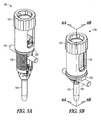
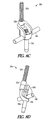
- a miniature rod reducer instrument 100 in accordance with an embodiment of the present invention includes an outer drive sleeve 110, a retaining guide ring 120, and a threaded tube 130.
- the rod reducer 100 is selectively engageable with a spinal rod 140 and a pedicle screw assembly 150, which can assume the form of a monoaxial pedicle screw, a sagittal screw, a polyaxial pedicle screw, a hook or nearly any type of screw that includes a head or anchor seat constructed to engage a distal end of the threaded tube 130.
- the outer drive sleeve 110 in an example, includes a proximal end, a distal end, a longitudinal axis between the proximal and distal ends, a cannulated interior, a gripping surface 112 disposed on a proximal exterior surface that may include a knurled or other traction grip surface, a visibility window 114 that enables viewing and weight reduction, a drive surface 116 such as a hex drive disposed interior to the proximal end and a series of interior threading 118 disposed on an interior surface at the distal end.
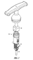
- the drive surface 116 in an example, is engageable with a ratcheting T-handle driver instrument ( FIG. 7 ) with a hex drive coupler 160 to impart additional mechanical rotational force to the outer drive sleeve 110 to assist in rod reduction.
- the threaded tube 130 includes a proximal end, a distal end, a longitudinal axis extending between the proximal and distal ends, a cannulated interior, a first leg 132 and a second leg 134.
- the first and second legs 132, 134 are held together by the interior confines of the outer drive sleeve 110 and the retaining guide ring 120.
- the first leg 132 includes an exterior threading 136A and the second leg 134 includes an exterior threading 136B.
- the exterior threading 136A, 136B can be a single or multi-lead thread to provide for faster reduction speed.
- the exterior threading 136A, 136B is a two start M18x1.5 with an effective pitch of 3 mm.
- the first leg 132 includes an engagement feature 138A interior to its distal end and the second leg 134 includes an engagement feature 138B interior to its distal end.
- the engagement features 138A, 138B selectively engage and couple to the exterior surface of a pedicle screw assembly 150.
- the engagement features 138A, 138B are comprised of male protrusions that mate with female receptacles inherent on the exterior surface of the pedicle screw assembly 150.
- the engagement features 138A, 138B and their corresponding receptacles provide stabilization in all three axes, as is best shown in FIG. 6A .
- the first leg 132 includes an exteriorly disposed feature 139A near the proximal end and the second leg 134 includes an exteriorly disposed feature 139B near the proximal end.
- the exteriorly disposed features 139A, 139B are comprised of regions in which the outer diameter of the threaded tube 130 and the pitch diameter of the exterior threading 136A, 136B decrease to allow the first and second arms 132, 134 to splay open slightly at the distal end to enable easy introduction of the rod reducer 100 over the pedicle screw assembly 150 and corresponding engagement of the engagement features 138A, 138B with the receptacles of the pedicle screw assembly 150.
- the first and second arms 132, 134 are configured to splay open at the distal end approximately 2.5 degrees in an example.
- the retaining guide ring 120 is disposed around the threaded tube 130 at the distal end of the outer drive sleeve 110 and includes first and second upwardly extending arms 122A, 122B, first and second outwardly extending tabs 124A, 124B disposed on ends of the upwardly extending arms 122A, 122B, respectively, and a rod recess 126 disposed at the distal end of the retaining guide ring 120 that selectively interfaces with the spinal rod 140.
- the outer drive sleeve 110 is constructed of stainless steel, titanium, or other biocompatible surgical grade metal, while the retaining guide ring 120 and threaded tube 130 are constructed of a biocompatible polymer material such as polyetheretherketone (PEEK).
- PEEK polyetheretherketone
- the drive sleeve 110 is not limited to metallic constructions and the retaining guide ring 120 and the threaded tube 130 are not limited to polymeric constructions and each may be constructed of any biocompatible material that is able to take on the general shape and withstand the normal operating conditions of the components.
- the retaining guide ring 120 and threaded tube 130 may be constructed of titanium and the drive sleeve 110 may be constructed of PEEK.
- a pedicle screw or several pedicle screw assemblies 150 are implanted into the vertebrae of a patient and the rod 140 may be pre-bent for potential deformity correction.
- the spinal rod 140 is loosely placed above the construct of pedicle screws 150 and attached to the pedicle screws 150 in which no reduction is necessary.
- the gripping surface 112 of the outer drive sleeve 110 is engaged and rotated with respect to the threaded tube 130 using manual rotation and/or the outer drive sleeve 110 may be rotated using the ratcheting T-handle driver instrument with a hex drive coupler 160 via the drive surface 116.
- the retaining guide ring 120 surrounds the features 139A, 139B such that the distal ends of the first and second legs 132, 134 splay open.
- the distal end of the rod reducer 100 is placed over the spinal rod 140 and above a pedicle screw assembly 150 such that the first and second legs 132, 134 straddle the rod 140 and the engagement features 138A, 138B surround the corresponding receptacles on the pedicle screw assembly 150.
- the outer drive sleeve 110 is then rotated manually with respect to the threaded tube 130 via the gripping surface 112 and/or rotating the ratcheting T-handle driver instrument with a hex drive coupler 160 with such that the retaining guide ring 120 and the outer drive sleeve 110 travel distally with respect to the threaded tube 130 via the engagement of the interior threading 118 and the first and second exterior threading 136A, 136B, thereby causing the unsplaying of the distal ends of the first and second arms 132, 134, engagement of the first and second engagement features 138A, 138B with the receptacles on the pedicle screw 150, engagement of the rod recess 126 to the spinal rod 140, and downward translation of the spinal rod 140 with respect to the first and second legs 132, 134.
- a plurality of rod reducer instruments 100 can be utilized in this manner to gradually reduce the spinal rod 140 into a plurality of pedicle screw assemblies 150 over a plurality of spinal levels.
- the rod reducers 100 in an example, are slowly and systematically actuated to avoid overstressing the pedicle screw assemblies 150 and the interface with their corresponding vertebral bodies, which further allows for gradual stressing and stretching of soft tissue of the patient's spine while potentially correcting a deformity.
- the ratcheting T-handle driver instrument with a hex drive coupler 160 is then uncoupled from the outer drive sleeve 110 and locking caps, elements which serve to finally secure the spinal rod 140 with respect to the pedicle screw assemblies 150, are introduced through the rod reducers 100 via a locking cap channel provided by the interior geometry of the threaded tube 130.
- the locking caps can be coupled to the pedicle screw assemblies 150 using a cap driver instrument (not shown), which can be inserted through the rod reducer 100.
- the locking cap driver 160 has an engagement feature for coupling to the locking caps and actuating their coupling to the pedicle screw assemblies 150, such as a threaded, star drive, or hex drive engagement feature.
- the locking cap driver 160 may be a ratcheting driver, but is not so limited.
- the locking caps are coupled to the pedicle screw assemblies 150 and the locking cap driver 160 is uncoupled from the rod reducers 100.
- the rod reducer(s) 100 are uncoupled from the pedicle screw assemblies 150 by disposing the retaining guide ring 120 over the features 139A, 139B such that the distal ends of the arms 132, 134 are splayed open and the engagement features 138A, 138B are disengaged from their corresponding receptacles on the pedicle screw assembly(s) 150.
- the rod reducer 100 can be cleaned and sterilized for reuse.
- the rod reducer 100 does not introduce notches or mar the exterior of the spinal rod 140 during its reduction.
- the rod reducer 100 of some examples prevents splaying of the upwardly extending arms that form the rod-receiving channel of the pedicle screw assembly 150.
- the rod reducer 100 can be coupled to a pedicle screw assembly 150 prior to or subsequent to the implantation of the pedicle screw 150, according to surgeon preference.
- the rod reducer 100 can further be utilized to aid in derotation maneuvers of the spine during surgery.
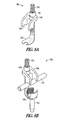
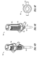
- a rod reducer 200 is provided that is configured especially for coupling to a monoaxial pedicle screw 250 and reducing a spinal rod 140 thereto.
- the rod reducer 200 includes a threaded shaft 210 terminating distally in a grasping element 220 for coupling to the underside of the distal end of a monoaxial pedicle screw assembly 250.
- the rod reducer 200 further includes a nut 230 configured to interface with the exterior threading of the shaft 210 and threadedly translate with respect thereto.
- a claw element 240 having one or more arms is coupled to the shaft 210 below the nut 230 and the one or more arms, in a further example, have a rod recess 242 for engaging the spinal rod 140.
- the grasping element 220 is placed under a monoaxial pedicle screw 250.
- the claw element 240 engages the proximal side of the spinal rod and the nut 230 is rotated to force the claw element 240 to reduce the rod 140 via the rod recess 242 into the monoaxial pedicle screw assembly 250.
- a locking cap is coupled to the monoaxial pedicle screw assembly 250 and the rod reducer 200 is decoupled from the monoaxial pedicle screw assembly 250 by loosening the nut 230 and disengaging the claw 240 from the spinal rod 140.
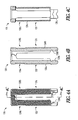
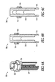
- a rod reducer 300 is provided that includes a hex nut 310, a threaded tube 330 having a first leg 332 and a second leg 334, and a retaining guide ring 320.
- the rod reducer 300 is similar in function and operation to the rod reducer 100 with the exception that instead of the outer drive sleeve 110, the hex nut 310 is included and functions in conjunction with a hex socket type instrument (not shown) to actuate the rod reducer 300.
- the threaded tube 330 is similar in function and operation to the threaded tube 130 but incorporates a hinge design at the proximal end to control the splaying of the first and second legs 332, 334.
Applications Claiming Priority (2)
| Application Number | Priority Date | Filing Date | Title |
|---|---|---|---|
| US13839208P | 2008-12-17 | 2008-12-17 | |
| PCT/US2009/006433 WO2010077284A1 (en) | 2008-12-17 | 2009-12-08 | Rod reducer apparatus for spinal corrective surgery |
Publications (2)
| Publication Number | Publication Date |
|---|---|
| EP2373238A1 EP2373238A1 (en) | 2011-10-12 |
| EP2373238B1 true EP2373238B1 (en) | 2013-09-25 |
Family
ID=41786245
Family Applications (1)
| Application Number | Title | Priority Date | Filing Date |
|---|---|---|---|
| EP09775382.6A Active EP2373238B1 (en) | 2008-12-17 | 2009-12-08 | Rod reducer apparatus for spinal corrective surgery |
Country Status (8)
| Country | Link |
|---|---|
| US (3) | US9161788B2 (ko) |
| EP (1) | EP2373238B1 (ko) |
| JP (1) | JP2012511997A (ko) |
| KR (1) | KR20110112306A (ko) |
| CN (1) | CN102256558A (ko) |
| BR (1) | BRPI0922953A2 (ko) |
| CA (1) | CA2746013A1 (ko) |
| WO (1) | WO2010077284A1 (ko) |
Families Citing this family (39)
| Publication number | Priority date | Publication date | Assignee | Title |
|---|---|---|---|---|
| US8439922B1 (en) | 2008-02-06 | 2013-05-14 | NiVasive, Inc. | Systems and methods for holding and implanting bone anchors |
| US9161788B2 (en) | 2008-12-17 | 2015-10-20 | DePuy Synthes Products, Inc. | Rod reducer apparatus for spinal corrective surgery |
| US8795283B2 (en) * | 2009-12-28 | 2014-08-05 | Safe Orthopaedics Sas | Instrument kit for performing spinal stabilization |
| US9393048B2 (en) | 2010-02-23 | 2016-07-19 | K2M, Inc. | Polyaxial bonescrew assembly |
| US8206395B2 (en) * | 2010-06-18 | 2012-06-26 | Spine Wave, Inc. | Surgical instrument and method for the distraction or compression of bones |
| US9393049B2 (en) | 2010-08-20 | 2016-07-19 | K2M, Inc. | Spinal fixation system |
| AU2011291476B2 (en) | 2010-08-20 | 2014-02-13 | K2M, Inc. | Spinal fixation system |
| AU2013201293B2 (en) * | 2010-08-20 | 2014-12-18 | K2M, Inc. | Spinal Fixation System |
| US9198698B1 (en) | 2011-02-10 | 2015-12-01 | Nuvasive, Inc. | Minimally invasive spinal fixation system and related methods |
| FR2976784B1 (fr) * | 2011-06-23 | 2013-07-05 | Spineway | Dispositif chirurgical pour la correction de la deformation de la colonne vertebrale |
| US9125703B2 (en) * | 2012-01-16 | 2015-09-08 | K2M, Inc. | Rod reducer, compressor, distractor system |
| FR2988993B1 (fr) * | 2012-04-05 | 2014-03-21 | Safe Orthopaedics | Instrument et systeme chirurgical pour la fixation des vertebres |
| EP2892452B1 (en) * | 2012-09-04 | 2018-08-15 | Sanpera Trigueros, Ignacio | System for a global three-dimensional correction of the curvatures of the spine |
| US9918752B2 (en) * | 2012-11-29 | 2018-03-20 | Warsaw Orthopedic, Inc. | Spinal implant system and method |
| US10136927B1 (en) | 2013-03-15 | 2018-11-27 | Nuvasive, Inc. | Rod reduction assemblies and related methods |
| US9486256B1 (en) | 2013-03-15 | 2016-11-08 | Nuvasive, Inc. | Rod reduction assemblies and related methods |
| US20150100098A1 (en) * | 2013-10-07 | 2015-04-09 | K2M, Inc. | Rod reducer |
| KR20160088889A (ko) * | 2013-11-22 | 2016-07-26 | 스파이널 밸런스, 인코포레이티드 | 다축 페디클 스크류 조립체 및 그의 패키징 |
| US9271768B2 (en) * | 2013-12-20 | 2016-03-01 | Globus Medical, Inc. | Orthopedic fixation devices and instruments for installation thereof |
| US20150313647A1 (en) | 2014-04-30 | 2015-11-05 | Ignacio Sanpera Trigueros | System for correction of the spine curvatures |
| WO2016000229A1 (en) * | 2014-07-02 | 2016-01-07 | Yue Zhou | Extension piece at nail end of pedicle nail, dilator and push rod reset lever |
| US9486257B2 (en) * | 2014-08-07 | 2016-11-08 | Jeffrey Scott Smith | Rod reduction tool and method to assist in the passage of a connecting rod between pedicle screws |
| DE102014114530A1 (de) * | 2014-10-07 | 2016-04-07 | Aesculap Ag | Sicherungshülse für eine Pedikelschraube |
| EP3092965B1 (en) * | 2015-05-15 | 2020-11-18 | Biedermann Technologies GmbH & Co. KG | Instrument for use with a bone anchoring device in spinal surgery and system including the instrument and a bone anchoring device |
| US9974577B1 (en) | 2015-05-21 | 2018-05-22 | Nuvasive, Inc. | Methods and instruments for performing leveraged reduction during single position spine surgery |
| US10123829B1 (en) | 2015-06-15 | 2018-11-13 | Nuvasive, Inc. | Reduction instruments and methods |
| DE102016106608A1 (de) * | 2016-04-11 | 2017-10-12 | Aesculap Ag | Instrument zum Führen eines Stabs in eine Implantataufnahme |
| US10524843B2 (en) | 2016-05-06 | 2020-01-07 | K2M, Inc. | Rotation shaft for a rod reducer |
| KR20190058452A (ko) * | 2016-07-04 | 2019-05-29 | 스파이널 밸런스, 인코포레이티드 | 척추경 나사용의 결합된 보호 용기 및 전달 디바이스 |
| US10398481B2 (en) | 2016-10-03 | 2019-09-03 | Nuvasive, Inc. | Spinal fixation system |
| WO2018071702A1 (en) * | 2016-10-12 | 2018-04-19 | Medical Accufix Llc | Methods and devices for medical device placement |
| US10779866B2 (en) | 2016-12-29 | 2020-09-22 | K2M, Inc. | Rod reducer assembly |
| US10485590B2 (en) | 2017-01-18 | 2019-11-26 | K2M, Inc. | Rod reducing device |
| WO2018204676A1 (en) | 2017-05-03 | 2018-11-08 | Advance Research System, Llc | Extension ready spinal support systems |
| US11648037B2 (en) | 2017-05-03 | 2023-05-16 | Advance Research System, Llc | Extension-ready spinal support system with vascular-safe pedicle screw |
| US10918424B2 (en) | 2018-03-12 | 2021-02-16 | Zimmer Biomet Spine, Inc. | Rod reducer ratchet lock-out mechanism |
| US11051861B2 (en) | 2018-06-13 | 2021-07-06 | Nuvasive, Inc. | Rod reduction assemblies and related methods |
| US20220160400A1 (en) * | 2019-03-12 | 2022-05-26 | Carbofix Spine Inc. | Composite material spinal implant |
| US11553947B2 (en) | 2019-07-16 | 2023-01-17 | Aesculap Implant Systems, Llc | Spinal deformity sequential persuader |
Family Cites Families (76)
| Publication number | Priority date | Publication date | Assignee | Title |
|---|---|---|---|---|
| US4411259A (en) | 1980-02-04 | 1983-10-25 | Drummond Denis S | Apparatus for engaging a hook assembly to a spinal column |
| US5020519A (en) | 1990-12-07 | 1991-06-04 | Zimmer, Inc. | Sagittal approximator |
| GB9110778D0 (en) | 1991-05-18 | 1991-07-10 | Middleton Jeffrey K | Apparatus for use in surgery |
| DE4238339C2 (de) | 1992-11-13 | 1994-10-06 | Peter Brehm | Pedikelschraube und Haltehaken zum Festlegen einer Versteifungsstange und Instrumentarium zum Justieren und Befestigen der Versteifungsstange an der Pedikelschraube oder dem Haltehaken |
| US5364397A (en) | 1993-06-01 | 1994-11-15 | Zimmer, Inc. | Spinal coupler seater with dual jaws and an independent plunger |
| US5584831A (en) * | 1993-07-09 | 1996-12-17 | September 28, Inc. | Spinal fixation device and method |
| US5616143A (en) | 1995-02-06 | 1997-04-01 | Schlapfer; Johannes F. | Surgical forceps |
| US5782830A (en) | 1995-10-16 | 1998-07-21 | Sdgi Holdings, Inc. | Implant insertion device |
| US6063088A (en) | 1997-03-24 | 2000-05-16 | United States Surgical Corporation | Method and instrumentation for implant insertion |
| US5720751A (en) | 1996-11-27 | 1998-02-24 | Jackson; Roger P. | Tools for use in seating spinal rods in open ended implants |
| US5910141A (en) | 1997-02-12 | 1999-06-08 | Sdgi Holdings, Inc. | Rod introduction apparatus |
| US5810878A (en) | 1997-02-12 | 1998-09-22 | Sdgi Holdings, Inc. | Rod introducer forceps |
| US6042582A (en) | 1997-05-20 | 2000-03-28 | Ray; Charles D. | Instrumentation and method for facilitating insertion of spinal implant |
| US5944720A (en) | 1998-03-25 | 1999-08-31 | Lipton; Glenn E | Posterior spinal fixation system |
| WO2002058600A2 (en) * | 2001-01-26 | 2002-08-01 | Osteotech, Inc. | Implant insertion tool |
| US7862587B2 (en) * | 2004-02-27 | 2011-01-04 | Jackson Roger P | Dynamic stabilization assemblies, tool set and method |
| US6440133B1 (en) | 2001-07-03 | 2002-08-27 | Sdgi Holdings, Inc. | Rod reducer instruments and methods |
| US8523913B2 (en) * | 2002-09-06 | 2013-09-03 | Roger P. Jackson | Helical guide and advancement flange with break-off extensions |
| EP2366349B1 (en) * | 2002-10-30 | 2017-04-05 | Zimmer Spine, Inc. | Spinal stabilization system insertion |
| US20060095035A1 (en) * | 2004-11-03 | 2006-05-04 | Jones Robert J | Instruments and methods for reduction of vertebral bodies |
| US7988698B2 (en) | 2003-01-28 | 2011-08-02 | Depuy Spine, Inc. | Spinal rod approximator |
| US7621918B2 (en) * | 2004-11-23 | 2009-11-24 | Jackson Roger P | Spinal fixation tool set and method |
| US7156849B2 (en) | 2003-06-16 | 2007-01-02 | Depuy Spine, Inc. | Rod reduction nut and driver tool |
| US8398682B2 (en) * | 2003-06-18 | 2013-03-19 | Roger P. Jackson | Polyaxial bone screw assembly |
| US20040267275A1 (en) | 2003-06-26 | 2004-12-30 | Cournoyer John R. | Spinal implant holder and rod reduction systems and methods |
| US7179261B2 (en) | 2003-12-16 | 2007-02-20 | Depuy Spine, Inc. | Percutaneous access devices and bone anchor assemblies |
| US7666188B2 (en) * | 2003-12-16 | 2010-02-23 | Depuy Spine, Inc. | Methods and devices for spinal fixation element placement |
| US8066739B2 (en) * | 2004-02-27 | 2011-11-29 | Jackson Roger P | Tool system for dynamic spinal implants |
| US7470279B2 (en) * | 2004-02-27 | 2008-12-30 | Jackson Roger P | Orthopedic implant rod reduction tool set and method |
| JP2007525274A (ja) * | 2004-02-27 | 2007-09-06 | ロジャー・ピー・ジャクソン | 整形外科インプラントロッド整復器具セット及び方法 |
| US8152810B2 (en) * | 2004-11-23 | 2012-04-10 | Jackson Roger P | Spinal fixation tool set and method |
| US7611517B2 (en) | 2004-02-27 | 2009-11-03 | Warsaw Orthopedic, Inc. | Rod reducer |
| JP4213609B2 (ja) * | 2004-03-09 | 2009-01-21 | 昭和医科工業株式会社 | ロッド固定用補助器具 |
| WO2007037772A2 (en) | 2004-07-06 | 2007-04-05 | Synthes (U.S.A.) | Spinal rod insertion instrument |
| US7572281B2 (en) | 2004-08-06 | 2009-08-11 | Depuy Spine, Inc. | Instrument for guiding a rod into an implant in a spinal fixation system |
| US7651502B2 (en) | 2004-09-24 | 2010-01-26 | Jackson Roger P | Spinal fixation tool set and method for rod reduction and fastener insertion |
| US7666189B2 (en) * | 2004-09-29 | 2010-02-23 | Synthes Usa, Llc | Less invasive surgical system and methods |
| EP1858422A4 (en) * | 2005-02-23 | 2011-12-28 | Pioneer Surgical Technology Inc | MINIMALLY INVASIVE SURGICAL SYSTEM |
| US7758617B2 (en) * | 2005-04-27 | 2010-07-20 | Globus Medical, Inc. | Percutaneous vertebral stabilization system |
| US7780706B2 (en) | 2005-04-27 | 2010-08-24 | Trinity Orthopedics, Llc | Mono-planar pedicle screw method, system and kit |
| US7491208B2 (en) | 2005-04-28 | 2009-02-17 | Warsaw Orthopedic, Inc. | Instrument and method for guiding surgical implants and instruments during surgery |
| US7608081B2 (en) | 2005-05-23 | 2009-10-27 | Custom Spine, Inc. | Rod reducer |
| US7771430B2 (en) | 2005-09-29 | 2010-08-10 | K2M, Inc. | Single action anti-torque rod reducer |
| US7931654B2 (en) * | 2006-03-09 | 2011-04-26 | K2M, Inc. | Dual action rod reducing and locking device and method |
| US7927334B2 (en) | 2006-04-11 | 2011-04-19 | Warsaw Orthopedic, Inc. | Multi-directional rod reducer instrument and method |
| US8216240B2 (en) | 2006-04-24 | 2012-07-10 | Warsaw Orthopedic | Cam based reduction instrument |
| US8192438B2 (en) | 2006-05-18 | 2012-06-05 | Phygen, LLC. | Rod reducer |
| US8551141B2 (en) * | 2006-08-23 | 2013-10-08 | Pioneer Surgical Technology, Inc. | Minimally invasive surgical system |
| US7686809B2 (en) | 2006-09-25 | 2010-03-30 | Stryker Spine | Rod inserter and rod with reduced diameter end |
| US8096996B2 (en) | 2007-03-20 | 2012-01-17 | Exactech, Inc. | Rod reducer |
| US9101401B2 (en) * | 2006-11-20 | 2015-08-11 | Aesculap Implant Systems, Llc | Bone repair device and method |
| US8679128B2 (en) | 2006-12-07 | 2014-03-25 | Zimmer Spine, Inc. | Apparatus and methods for reduction of vertebral bodies in a spine |
| US20080234765A1 (en) | 2007-03-13 | 2008-09-25 | Depuy Spine, Inc. | Rod reduction methods and devices |
| US8172847B2 (en) | 2007-03-29 | 2012-05-08 | Depuy Spine, Inc. | In-line rod reduction device and methods |
| US7947046B2 (en) * | 2007-06-21 | 2011-05-24 | Warsaw Orthopedic, Inc. | Anchor extenders for minimally invasive surgical procedures |
| US8048129B2 (en) * | 2007-08-15 | 2011-11-01 | Zimmer Spine, Inc. | MIS crosslink apparatus and methods for spinal implant |
| US8414588B2 (en) * | 2007-10-04 | 2013-04-09 | Depuy Spine, Inc. | Methods and devices for minimally invasive spinal connection element delivery |
| US8366714B2 (en) * | 2007-10-23 | 2013-02-05 | K2M, Inc. | Rod insertion instrument and method of use |
| US8540718B2 (en) * | 2007-10-23 | 2013-09-24 | Aesculap Implant Systems, Llc | Rod persuader |
| US8439922B1 (en) * | 2008-02-06 | 2013-05-14 | NiVasive, Inc. | Systems and methods for holding and implanting bone anchors |
| US8608746B2 (en) * | 2008-03-10 | 2013-12-17 | DePuy Synthes Products, LLC | Derotation instrument with reduction functionality |
| US8915944B2 (en) * | 2008-04-15 | 2014-12-23 | Perumala Corporation | Rod and plate system for incremental reduction of the spine |
| US9504494B2 (en) * | 2008-04-28 | 2016-11-29 | DePuy Synthes Products, Inc. | Implants for securing spinal fixation elements |
| AU2009261934B2 (en) * | 2008-06-27 | 2014-09-04 | K2M, Inc. | System and method for performing spinal surgery |
| US20100168796A1 (en) * | 2008-07-29 | 2010-07-01 | Kenneth Arden Eliasen | Bone anchoring member with clamp mechanism |
| US9161788B2 (en) * | 2008-12-17 | 2015-10-20 | DePuy Synthes Products, Inc. | Rod reducer apparatus for spinal corrective surgery |
| US8206394B2 (en) * | 2009-05-13 | 2012-06-26 | Depuy Spine, Inc. | Torque limited instrument for manipulating a spinal rod relative to a bone anchor |
| AU2010318704B2 (en) * | 2009-11-10 | 2015-07-09 | Nuvasive, Inc. | Method and apparatus for performing spinal surgery |
| US8545505B2 (en) * | 2010-01-15 | 2013-10-01 | Pioneer Surgical Technology, Inc. | Low friction rod persuader |
| US8523873B2 (en) * | 2010-04-08 | 2013-09-03 | Warsaw Orthopedic, Inc. | Neural-monitoring enabled sleeves for surgical instruments |
| US8206395B2 (en) * | 2010-06-18 | 2012-06-26 | Spine Wave, Inc. | Surgical instrument and method for the distraction or compression of bones |
| US8394108B2 (en) * | 2010-06-18 | 2013-03-12 | Spine Wave, Inc. | Screw driver for a multiaxial bone screw |
| US9186184B2 (en) * | 2011-02-14 | 2015-11-17 | Pioneer Surgical Technology, Inc. | Spinal fixation system and method |
| US8764756B2 (en) * | 2011-02-22 | 2014-07-01 | K2M, Inc. | Single action anti-torque rod reducer |
| US8439924B1 (en) * | 2012-04-02 | 2013-05-14 | Warsaw Orthopedic, Inc. | Spinal implant system and method |
| US20140343613A1 (en) * | 2013-05-17 | 2014-11-20 | Kenneth Arden Eliasen | Bone anchoring member with clamp mechanism |
-
2009
- 2009-12-08 US US13/139,373 patent/US9161788B2/en active Active
- 2009-12-08 CN CN2009801507487A patent/CN102256558A/zh active Pending
- 2009-12-08 EP EP09775382.6A patent/EP2373238B1/en active Active
- 2009-12-08 CA CA2746013A patent/CA2746013A1/en not_active Abandoned
- 2009-12-08 WO PCT/US2009/006433 patent/WO2010077284A1/en active Application Filing
- 2009-12-08 BR BRPI0922953A patent/BRPI0922953A2/pt not_active IP Right Cessation
- 2009-12-08 KR KR1020117014613A patent/KR20110112306A/ko not_active Application Discontinuation
- 2009-12-08 JP JP2011542114A patent/JP2012511997A/ja not_active Abandoned
-
2015
- 2015-09-15 US US14/854,424 patent/US9636152B2/en active Active
-
2017
- 2017-04-05 US US15/479,789 patent/US9962198B2/en active Active
Also Published As
| Publication number | Publication date |
|---|---|
| US20160000479A1 (en) | 2016-01-07 |
| WO2010077284A1 (en) | 2010-07-08 |
| CA2746013A1 (en) | 2011-07-08 |
| BRPI0922953A2 (pt) | 2016-01-19 |
| US20170202583A1 (en) | 2017-07-20 |
| US9636152B2 (en) | 2017-05-02 |
| US9962198B2 (en) | 2018-05-08 |
| CN102256558A (zh) | 2011-11-23 |
| US9161788B2 (en) | 2015-10-20 |
| EP2373238A1 (en) | 2011-10-12 |
| KR20110112306A (ko) | 2011-10-12 |
| US20120271365A1 (en) | 2012-10-25 |
| JP2012511997A (ja) | 2012-05-31 |
Similar Documents
| Publication | Publication Date | Title |
|---|---|---|
| EP2373238B1 (en) | Rod reducer apparatus for spinal corrective surgery | |
| US9943343B2 (en) | Instrument and method for reducing and securing spinal rods | |
| EP2187825B1 (en) | Spinal crosslink apparatus for minimally invasive surgery | |
| AU2011276535B2 (en) | Spinal stabilization system | |
| US9241738B2 (en) | CAM lock pedicle screw | |
| US8696717B2 (en) | Multi-planar, taper lock screw with additional lock | |
| US20150066091A1 (en) | Systems for vertebral adjustments and rod reduction | |
| US20120203288A1 (en) | Spinal fixation system and screwdriver tool for use with the same | |
| US20110319938A1 (en) | Coplanar deformity correction system | |
| US20140336709A1 (en) | Multi-threaded pedicle screw system | |
| US20110172674A1 (en) | System and Methods for Minimally Invasive Spine Surgery | |
| US20130150864A1 (en) | Surgical instrument and method | |
| US20180049776A1 (en) | Spinal stabilization system | |
| US20170348029A1 (en) | RCDF Instrument, Apparatus and Procedures | |
| WO2011057178A1 (en) | System and method for stabilizing and fixating lumbar vertebrae | |
| US20150282847A1 (en) | Method of Positioning Pedicle Screws and Spinal Rods and Apparatuses for the Same | |
| US11529173B1 (en) | Reduction system for spondylolisthesis | |
| EP3952767B1 (en) | A polyaxial surgical screw and device for implanting said surgical screw | |
| JP2024518177A (ja) | 脊椎椎骨の椎弓根ねじ安定化のためのシステム及び方法 | |
| AU2015203073B2 (en) | Spinal stabilization system |
Legal Events
| Date | Code | Title | Description |
|---|---|---|---|
| PUAI | Public reference made under article 153(3) epc to a published international application that has entered the european phase |
Free format text: ORIGINAL CODE: 0009012 |
|
| 17P | Request for examination filed |
Effective date: 20110708 |
|
| AK | Designated contracting states |
Kind code of ref document: A1 Designated state(s): AT BE BG CH CY CZ DE DK EE ES FI FR GB GR HR HU IE IS IT LI LT LU LV MC MK MT NL NO PL PT RO SE SI SK SM TR |
|
| DAX | Request for extension of the european patent (deleted) | ||
| REG | Reference to a national code |
Ref country code: DE Ref legal event code: R079 Ref document number: 602009019082 Country of ref document: DE Free format text: PREVIOUS MAIN CLASS: A61B0017880000 Ipc: A61B0017700000 |
|
| RIC1 | Information provided on ipc code assigned before grant |
Ipc: A61B 17/70 20060101AFI20130213BHEP |
|
| GRAP | Despatch of communication of intention to grant a patent |
Free format text: ORIGINAL CODE: EPIDOSNIGR1 |
|
| INTG | Intention to grant announced |
Effective date: 20130411 |
|
| GRAS | Grant fee paid |
Free format text: ORIGINAL CODE: EPIDOSNIGR3 |
|
| GRAA | (expected) grant |
Free format text: ORIGINAL CODE: 0009210 |
|
| AK | Designated contracting states |
Kind code of ref document: B1 Designated state(s): AT BE BG CH CY CZ DE DK EE ES FI FR GB GR HR HU IE IS IT LI LT LU LV MC MK MT NL NO PL PT RO SE SI SK SM TR |
|
| REG | Reference to a national code |
Ref country code: GB Ref legal event code: FG4D |
|
| REG | Reference to a national code |
Ref country code: CH Ref legal event code: EP |
|
| REG | Reference to a national code |
Ref country code: AT Ref legal event code: REF Ref document number: 633426 Country of ref document: AT Kind code of ref document: T Effective date: 20131015 |
|
| REG | Reference to a national code |
Ref country code: IE Ref legal event code: FG4D |
|
| REG | Reference to a national code |
Ref country code: DE Ref legal event code: R096 Ref document number: 602009019082 Country of ref document: DE Effective date: 20131121 |
|
| REG | Reference to a national code |
Ref country code: CH Ref legal event code: NV Representative=s name: E. BLUM AND CO. AG PATENT- UND MARKENANWAELTE , CH |
|
| PG25 | Lapsed in a contracting state [announced via postgrant information from national office to epo] |
Ref country code: HR Free format text: LAPSE BECAUSE OF FAILURE TO SUBMIT A TRANSLATION OF THE DESCRIPTION OR TO PAY THE FEE WITHIN THE PRESCRIBED TIME-LIMIT Effective date: 20130925 Ref country code: LT Free format text: LAPSE BECAUSE OF FAILURE TO SUBMIT A TRANSLATION OF THE DESCRIPTION OR TO PAY THE FEE WITHIN THE PRESCRIBED TIME-LIMIT Effective date: 20130925 Ref country code: SE Free format text: LAPSE BECAUSE OF FAILURE TO SUBMIT A TRANSLATION OF THE DESCRIPTION OR TO PAY THE FEE WITHIN THE PRESCRIBED TIME-LIMIT Effective date: 20130925 Ref country code: NO Free format text: LAPSE BECAUSE OF FAILURE TO SUBMIT A TRANSLATION OF THE DESCRIPTION OR TO PAY THE FEE WITHIN THE PRESCRIBED TIME-LIMIT Effective date: 20131225 |
|
| REG | Reference to a national code |
Ref country code: AT Ref legal event code: MK05 Ref document number: 633426 Country of ref document: AT Kind code of ref document: T Effective date: 20130925 |
|
| REG | Reference to a national code |
Ref country code: NL Ref legal event code: VDEP Effective date: 20130925 |
|
| REG | Reference to a national code |
Ref country code: LT Ref legal event code: MG4D |
|
| PG25 | Lapsed in a contracting state [announced via postgrant information from national office to epo] |
Ref country code: SI Free format text: LAPSE BECAUSE OF FAILURE TO SUBMIT A TRANSLATION OF THE DESCRIPTION OR TO PAY THE FEE WITHIN THE PRESCRIBED TIME-LIMIT Effective date: 20130925 Ref country code: LV Free format text: LAPSE BECAUSE OF FAILURE TO SUBMIT A TRANSLATION OF THE DESCRIPTION OR TO PAY THE FEE WITHIN THE PRESCRIBED TIME-LIMIT Effective date: 20130925 Ref country code: GR Free format text: LAPSE BECAUSE OF FAILURE TO SUBMIT A TRANSLATION OF THE DESCRIPTION OR TO PAY THE FEE WITHIN THE PRESCRIBED TIME-LIMIT Effective date: 20131226 Ref country code: FI Free format text: LAPSE BECAUSE OF FAILURE TO SUBMIT A TRANSLATION OF THE DESCRIPTION OR TO PAY THE FEE WITHIN THE PRESCRIBED TIME-LIMIT Effective date: 20130925 |
|
| PG25 | Lapsed in a contracting state [announced via postgrant information from national office to epo] |
Ref country code: BE Free format text: LAPSE BECAUSE OF FAILURE TO SUBMIT A TRANSLATION OF THE DESCRIPTION OR TO PAY THE FEE WITHIN THE PRESCRIBED TIME-LIMIT Effective date: 20130925 |
|
| PG25 | Lapsed in a contracting state [announced via postgrant information from national office to epo] |
Ref country code: NL Free format text: LAPSE BECAUSE OF FAILURE TO SUBMIT A TRANSLATION OF THE DESCRIPTION OR TO PAY THE FEE WITHIN THE PRESCRIBED TIME-LIMIT Effective date: 20130925 Ref country code: RO Free format text: LAPSE BECAUSE OF FAILURE TO SUBMIT A TRANSLATION OF THE DESCRIPTION OR TO PAY THE FEE WITHIN THE PRESCRIBED TIME-LIMIT Effective date: 20130925 Ref country code: IS Free format text: LAPSE BECAUSE OF FAILURE TO SUBMIT A TRANSLATION OF THE DESCRIPTION OR TO PAY THE FEE WITHIN THE PRESCRIBED TIME-LIMIT Effective date: 20140125 Ref country code: EE Free format text: LAPSE BECAUSE OF FAILURE TO SUBMIT A TRANSLATION OF THE DESCRIPTION OR TO PAY THE FEE WITHIN THE PRESCRIBED TIME-LIMIT Effective date: 20130925 Ref country code: CZ Free format text: LAPSE BECAUSE OF FAILURE TO SUBMIT A TRANSLATION OF THE DESCRIPTION OR TO PAY THE FEE WITHIN THE PRESCRIBED TIME-LIMIT Effective date: 20130925 Ref country code: SK Free format text: LAPSE BECAUSE OF FAILURE TO SUBMIT A TRANSLATION OF THE DESCRIPTION OR TO PAY THE FEE WITHIN THE PRESCRIBED TIME-LIMIT Effective date: 20130925 |
|
| PG25 | Lapsed in a contracting state [announced via postgrant information from national office to epo] |
Ref country code: AT Free format text: LAPSE BECAUSE OF FAILURE TO SUBMIT A TRANSLATION OF THE DESCRIPTION OR TO PAY THE FEE WITHIN THE PRESCRIBED TIME-LIMIT Effective date: 20130925 Ref country code: ES Free format text: LAPSE BECAUSE OF FAILURE TO SUBMIT A TRANSLATION OF THE DESCRIPTION OR TO PAY THE FEE WITHIN THE PRESCRIBED TIME-LIMIT Effective date: 20130925 Ref country code: PL Free format text: LAPSE BECAUSE OF FAILURE TO SUBMIT A TRANSLATION OF THE DESCRIPTION OR TO PAY THE FEE WITHIN THE PRESCRIBED TIME-LIMIT Effective date: 20130925 Ref country code: CY Free format text: LAPSE BECAUSE OF FAILURE TO SUBMIT A TRANSLATION OF THE DESCRIPTION OR TO PAY THE FEE WITHIN THE PRESCRIBED TIME-LIMIT Effective date: 20130925 |
|
| REG | Reference to a national code |
Ref country code: DE Ref legal event code: R097 Ref document number: 602009019082 Country of ref document: DE |
|
| PG25 | Lapsed in a contracting state [announced via postgrant information from national office to epo] |
Ref country code: PT Free format text: LAPSE BECAUSE OF FAILURE TO SUBMIT A TRANSLATION OF THE DESCRIPTION OR TO PAY THE FEE WITHIN THE PRESCRIBED TIME-LIMIT Effective date: 20140127 |
|
| PLBE | No opposition filed within time limit |
Free format text: ORIGINAL CODE: 0009261 |
|
| STAA | Information on the status of an ep patent application or granted ep patent |
Free format text: STATUS: NO OPPOSITION FILED WITHIN TIME LIMIT |
|
| PG25 | Lapsed in a contracting state [announced via postgrant information from national office to epo] |
Ref country code: LU Free format text: LAPSE BECAUSE OF FAILURE TO SUBMIT A TRANSLATION OF THE DESCRIPTION OR TO PAY THE FEE WITHIN THE PRESCRIBED TIME-LIMIT Effective date: 20131208 Ref country code: IT Free format text: LAPSE BECAUSE OF FAILURE TO SUBMIT A TRANSLATION OF THE DESCRIPTION OR TO PAY THE FEE WITHIN THE PRESCRIBED TIME-LIMIT Effective date: 20130925 |
|
| 26N | No opposition filed |
Effective date: 20140626 |
|
| REG | Reference to a national code |
Ref country code: IE Ref legal event code: MM4A |
|
| REG | Reference to a national code |
Ref country code: FR Ref legal event code: ST Effective date: 20140829 |
|
| PG25 | Lapsed in a contracting state [announced via postgrant information from national office to epo] |
Ref country code: DK Free format text: LAPSE BECAUSE OF FAILURE TO SUBMIT A TRANSLATION OF THE DESCRIPTION OR TO PAY THE FEE WITHIN THE PRESCRIBED TIME-LIMIT Effective date: 20130925 |
|
| REG | Reference to a national code |
Ref country code: DE Ref legal event code: R097 Ref document number: 602009019082 Country of ref document: DE Effective date: 20140626 |
|
| PG25 | Lapsed in a contracting state [announced via postgrant information from national office to epo] |
Ref country code: IE Free format text: LAPSE BECAUSE OF NON-PAYMENT OF DUE FEES Effective date: 20131208 |
|
| PG25 | Lapsed in a contracting state [announced via postgrant information from national office to epo] |
Ref country code: FR Free format text: LAPSE BECAUSE OF NON-PAYMENT OF DUE FEES Effective date: 20131231 |
|
| PG25 | Lapsed in a contracting state [announced via postgrant information from national office to epo] |
Ref country code: MC Free format text: LAPSE BECAUSE OF FAILURE TO SUBMIT A TRANSLATION OF THE DESCRIPTION OR TO PAY THE FEE WITHIN THE PRESCRIBED TIME-LIMIT Effective date: 20130925 |
|
| PG25 | Lapsed in a contracting state [announced via postgrant information from national office to epo] |
Ref country code: SM Free format text: LAPSE BECAUSE OF FAILURE TO SUBMIT A TRANSLATION OF THE DESCRIPTION OR TO PAY THE FEE WITHIN THE PRESCRIBED TIME-LIMIT Effective date: 20130925 |
|
| PG25 | Lapsed in a contracting state [announced via postgrant information from national office to epo] |
Ref country code: TR Free format text: LAPSE BECAUSE OF FAILURE TO SUBMIT A TRANSLATION OF THE DESCRIPTION OR TO PAY THE FEE WITHIN THE PRESCRIBED TIME-LIMIT Effective date: 20130925 |
|
| PG25 | Lapsed in a contracting state [announced via postgrant information from national office to epo] |
Ref country code: HU Free format text: LAPSE BECAUSE OF FAILURE TO SUBMIT A TRANSLATION OF THE DESCRIPTION OR TO PAY THE FEE WITHIN THE PRESCRIBED TIME-LIMIT; INVALID AB INITIO Effective date: 20091208 Ref country code: BG Free format text: LAPSE BECAUSE OF FAILURE TO SUBMIT A TRANSLATION OF THE DESCRIPTION OR TO PAY THE FEE WITHIN THE PRESCRIBED TIME-LIMIT Effective date: 20130925 Ref country code: MK Free format text: LAPSE BECAUSE OF FAILURE TO SUBMIT A TRANSLATION OF THE DESCRIPTION OR TO PAY THE FEE WITHIN THE PRESCRIBED TIME-LIMIT Effective date: 20130925 |
|
| PG25 | Lapsed in a contracting state [announced via postgrant information from national office to epo] |
Ref country code: MT Free format text: LAPSE BECAUSE OF FAILURE TO SUBMIT A TRANSLATION OF THE DESCRIPTION OR TO PAY THE FEE WITHIN THE PRESCRIBED TIME-LIMIT Effective date: 20130925 |
|
| REG | Reference to a national code |
Ref country code: DE Ref legal event code: R082 Ref document number: 602009019082 Country of ref document: DE Representative=s name: KLUNKER IP PATENTANWAELTE PARTG MBB, DE |
|
| PGFP | Annual fee paid to national office [announced via postgrant information from national office to epo] |
Ref country code: CH Payment date: 20230101 Year of fee payment: 14 |
|
| PGFP | Annual fee paid to national office [announced via postgrant information from national office to epo] |
Ref country code: GB Payment date: 20231102 Year of fee payment: 15 |
|
| PGFP | Annual fee paid to national office [announced via postgrant information from national office to epo] |
Ref country code: DE Payment date: 20231031 Year of fee payment: 15 |
|
| PGFP | Annual fee paid to national office [announced via postgrant information from national office to epo] |
Ref country code: CH Payment date: 20240101 Year of fee payment: 15 |