EP2372900A1 - Motor control device - Google Patents
Motor control device Download PDFInfo
- Publication number
- EP2372900A1 EP2372900A1 EP09834623A EP09834623A EP2372900A1 EP 2372900 A1 EP2372900 A1 EP 2372900A1 EP 09834623 A EP09834623 A EP 09834623A EP 09834623 A EP09834623 A EP 09834623A EP 2372900 A1 EP2372900 A1 EP 2372900A1
- Authority
- EP
- European Patent Office
- Prior art keywords
- inverter
- phase
- short
- switching elements
- electric motor
- Prior art date
- Legal status (The legal status is an assumption and is not a legal conclusion. Google has not performed a legal analysis and makes no representation as to the accuracy of the status listed.)
- Withdrawn
Links
Images


Classifications
-
- H—ELECTRICITY
- H02—GENERATION; CONVERSION OR DISTRIBUTION OF ELECTRIC POWER
- H02P—CONTROL OR REGULATION OF ELECTRIC MOTORS, ELECTRIC GENERATORS OR DYNAMO-ELECTRIC CONVERTERS; CONTROLLING TRANSFORMERS, REACTORS OR CHOKE COILS
- H02P27/00—Arrangements or methods for the control of AC motors characterised by the kind of supply voltage
- H02P27/04—Arrangements or methods for the control of AC motors characterised by the kind of supply voltage using variable-frequency supply voltage, e.g. inverter or converter supply voltage
- H02P27/06—Arrangements or methods for the control of AC motors characterised by the kind of supply voltage using variable-frequency supply voltage, e.g. inverter or converter supply voltage using dc to ac converters or inverters
-
- B—PERFORMING OPERATIONS; TRANSPORTING
- B60—VEHICLES IN GENERAL
- B60L—PROPULSION OF ELECTRICALLY-PROPELLED VEHICLES; SUPPLYING ELECTRIC POWER FOR AUXILIARY EQUIPMENT OF ELECTRICALLY-PROPELLED VEHICLES; ELECTRODYNAMIC BRAKE SYSTEMS FOR VEHICLES IN GENERAL; MAGNETIC SUSPENSION OR LEVITATION FOR VEHICLES; MONITORING OPERATING VARIABLES OF ELECTRICALLY-PROPELLED VEHICLES; ELECTRIC SAFETY DEVICES FOR ELECTRICALLY-PROPELLED VEHICLES
- B60L3/00—Electric devices on electrically-propelled vehicles for safety purposes; Monitoring operating variables, e.g. speed, deceleration or energy consumption
- B60L3/0023—Detecting, eliminating, remedying or compensating for drive train abnormalities, e.g. failures within the drive train
- B60L3/003—Detecting, eliminating, remedying or compensating for drive train abnormalities, e.g. failures within the drive train relating to inverters
-
- B—PERFORMING OPERATIONS; TRANSPORTING
- B60—VEHICLES IN GENERAL
- B60L—PROPULSION OF ELECTRICALLY-PROPELLED VEHICLES; SUPPLYING ELECTRIC POWER FOR AUXILIARY EQUIPMENT OF ELECTRICALLY-PROPELLED VEHICLES; ELECTRODYNAMIC BRAKE SYSTEMS FOR VEHICLES IN GENERAL; MAGNETIC SUSPENSION OR LEVITATION FOR VEHICLES; MONITORING OPERATING VARIABLES OF ELECTRICALLY-PROPELLED VEHICLES; ELECTRIC SAFETY DEVICES FOR ELECTRICALLY-PROPELLED VEHICLES
- B60L50/00—Electric propulsion with power supplied within the vehicle
- B60L50/10—Electric propulsion with power supplied within the vehicle using propulsion power supplied by engine-driven generators, e.g. generators driven by combustion engines
- B60L50/16—Electric propulsion with power supplied within the vehicle using propulsion power supplied by engine-driven generators, e.g. generators driven by combustion engines with provision for separate direct mechanical propulsion
-
- H—ELECTRICITY
- H02—GENERATION; CONVERSION OR DISTRIBUTION OF ELECTRIC POWER
- H02P—CONTROL OR REGULATION OF ELECTRIC MOTORS, ELECTRIC GENERATORS OR DYNAMO-ELECTRIC CONVERTERS; CONTROLLING TRANSFORMERS, REACTORS OR CHOKE COILS
- H02P29/00—Arrangements for regulating or controlling electric motors, appropriate for both AC and DC motors
- H02P29/02—Providing protection against overload without automatic interruption of supply
- H02P29/024—Detecting a fault condition, e.g. short circuit, locked rotor, open circuit or loss of load
- H02P29/0241—Detecting a fault condition, e.g. short circuit, locked rotor, open circuit or loss of load the fault being an overvoltage
-
- H—ELECTRICITY
- H02—GENERATION; CONVERSION OR DISTRIBUTION OF ELECTRIC POWER
- H02M—APPARATUS FOR CONVERSION BETWEEN AC AND AC, BETWEEN AC AND DC, OR BETWEEN DC AND DC, AND FOR USE WITH MAINS OR SIMILAR POWER SUPPLY SYSTEMS; CONVERSION OF DC OR AC INPUT POWER INTO SURGE OUTPUT POWER; CONTROL OR REGULATION THEREOF
- H02M1/00—Details of apparatus for conversion
- H02M1/0003—Details of control, feedback or regulation circuits
- H02M1/0009—Devices or circuits for detecting current in a converter
-
- Y—GENERAL TAGGING OF NEW TECHNOLOGICAL DEVELOPMENTS; GENERAL TAGGING OF CROSS-SECTIONAL TECHNOLOGIES SPANNING OVER SEVERAL SECTIONS OF THE IPC; TECHNICAL SUBJECTS COVERED BY FORMER USPC CROSS-REFERENCE ART COLLECTIONS [XRACs] AND DIGESTS
- Y02—TECHNOLOGIES OR APPLICATIONS FOR MITIGATION OR ADAPTATION AGAINST CLIMATE CHANGE
- Y02T—CLIMATE CHANGE MITIGATION TECHNOLOGIES RELATED TO TRANSPORTATION
- Y02T10/00—Road transport of goods or passengers
- Y02T10/60—Other road transportation technologies with climate change mitigation effect
- Y02T10/64—Electric machine technologies in electromobility
-
- Y—GENERAL TAGGING OF NEW TECHNOLOGICAL DEVELOPMENTS; GENERAL TAGGING OF CROSS-SECTIONAL TECHNOLOGIES SPANNING OVER SEVERAL SECTIONS OF THE IPC; TECHNICAL SUBJECTS COVERED BY FORMER USPC CROSS-REFERENCE ART COLLECTIONS [XRACs] AND DIGESTS
- Y02—TECHNOLOGIES OR APPLICATIONS FOR MITIGATION OR ADAPTATION AGAINST CLIMATE CHANGE
- Y02T—CLIMATE CHANGE MITIGATION TECHNOLOGIES RELATED TO TRANSPORTATION
- Y02T10/00—Road transport of goods or passengers
- Y02T10/60—Other road transportation technologies with climate change mitigation effect
- Y02T10/70—Energy storage systems for electromobility, e.g. batteries
-
- Y—GENERAL TAGGING OF NEW TECHNOLOGICAL DEVELOPMENTS; GENERAL TAGGING OF CROSS-SECTIONAL TECHNOLOGIES SPANNING OVER SEVERAL SECTIONS OF THE IPC; TECHNICAL SUBJECTS COVERED BY FORMER USPC CROSS-REFERENCE ART COLLECTIONS [XRACs] AND DIGESTS
- Y02—TECHNOLOGIES OR APPLICATIONS FOR MITIGATION OR ADAPTATION AGAINST CLIMATE CHANGE
- Y02T—CLIMATE CHANGE MITIGATION TECHNOLOGIES RELATED TO TRANSPORTATION
- Y02T10/00—Road transport of goods or passengers
- Y02T10/60—Other road transportation technologies with climate change mitigation effect
- Y02T10/7072—Electromobility specific charging systems or methods for batteries, ultracapacitors, supercapacitors or double-layer capacitors
Definitions
- the present invention relates to a control system for an electric motor to which electric power is supplied from a DC power supply via a multi-phase inverter in which a switch unit including a switching element and a reflux diode connected in parallel to the switching element is provided on each of a positive side and a negative side of each of arms of respective phases.
- FIG. 14 is a block diagram of an internal configuration of the HEV.
- driving force from an internal combustion engine (ENG) 107 and/or an electric motor (MOT) 101 is transmitted to drive wheels 153 via a gearbox 109 and a drive shaft 151.
- a rotor of the electric motor 101 is connected directly to a drive shaft of the internal combustion engine 107.
- the rotor of the electric motor 101 also rotates.
- the internal combustion engine 107 generates a driving force (an output torque) to run the vehicle.
- An engine ECU (ENG ECU) 117 controls the internal combustion engine 107.
- the electric motor 101 is a three-phase AC motor, for example, and generates a driving force (an output torque) to run the vehicle.
- a motor ECU (MOT ECU) 119 controls the electric motor 101.
- a battery (BATT) 103 is a DC power supply and supplies electric power to the electric motor 101 via an inverter 105.
- the output voltage of the battery 103 is a high voltage (for example, 100 to 200V).
- the inverter 105 converts a DC current from the battery 103 into three phase AC currents.
- An inverter ECU (INV ECU) 111 controls the inverter 105.
- a clutch 113 interrupts or connects a transmission line of driving force from the internal engine 107 and/or the electric motor 101 to the drive wheels 153 based on an instruction from a management ECU 115.
- the clutch 113 is disengaged, the driving force is not transmitted to the drive wheels 153, but the clutch 113 is engaged, the drive force is transmitted to the drive wheel 153.
- the gearbox 109 is a transmission which converts the driving force from the internal combustion engine 107 and/or the electric motor 101 into a rotational speed and torque at desirable gear ratios for transmission to the drive shaft 151.
- the management ECU (MG ECU) 115 controls the internal combustion engine 107, the electric motor 101 and the inverter 105, instructs the clutch 113 to be engaged or disengaged and instructs the gearbox 109 to change the gear ratios thereof.
- Fig. 15 is a block diagram of a driving system installed in the vehicle shown in Fig. 14 for driving the electric motor 101.
- arms 1u, 1v, 1w are provided correspondingly with phases (U phase, V phase, W phase) of the electric motor 101, and the arms 1u, 1v, 1w are connected in parallel to a smoothing capacitor C between power supply terminals 2a, 2b.
- Central points of the respective arms 1u, 1v, 1w are connected to a U-phase armature Au, a V-phase armature Av and a W-phase armature Aw of the electric motor 101, respectively.
- a switch unit includes a switching element such as IBGT or MOSFET and a reflux diode connected in parallel to the switching element.
- Such switch unit is provided on each of a positive side and a negative side on each of the respective arums.
- a switch unit 5a including a switching element 3a and a reflux diode 4a is provided on a positive side
- a switch unit 5b including a switching element 3b and a reflux diode 4b is provided on a negative side.
- a collector of the positive-side switching element 3a and a cathode of the positive-side reflux diode 4a are connected to the positive-side power supply terminal 2a, and an emitter of the negative-side switching element 3b and an anode of the negative-side reflux diode 4b are connected to the negative-side power supply terminal 2b.
- a positive terminal of the battery 103 is connected to the positive-side power supply terminal 2a via a contactor SW.
- Each switching element is on/off controlled by a control signal from the inverter ECU 111.
- a gate resistor R is connected to a gate terminal of each switching element, and a control signal from the inverter ECU 111 is inputted into the gate terminal via the gate resistor R.
- Patent Document 1 when the switching element of the switching portion 5b to which a U-phase current flows short-circuits to fail, the inverter ECU 111 on controls the switching elements of the switching portions 5b which are provided on the negative side and off controls the switching elements of the switch units 5a which are provided on the positive side. Consequently, there is produced a state in which inverter 105 side ends of the armatures Au, Av, Aw of the respective phases of the electric motor 101 are substantially short-circuited relative to each other.
- a control to generate the three-phase short-circuited state in the electric motor 101 will be referred to as a "three-phase short-circuiting control.”
- Fig. 16 shows examples of waveforms of the respective phases which are generated when the rotor of the electric motor 101 which is in the three-phase short-circuited state is rotated by driving the internal combustion engine 107.
- Patent Document 1 JP-2008-220045-A
- the inverter ECU 222 PWM controls the inverter 105 so that the two switching elements 3a, 3b of each arm are not put in an ON state (an energized state) simultaneously.
- the switch units 5a, 5b of the arm including the short-circuited switch unit are energized simultaneously.
- the electric motor 101 is in operation, electric power is supplied from the battery 103 and is received by the electric motor 101. Consequently, a great current (a short-circuit current) flows to both the switch units 5a, 5b of the arm including the short-circuited switch unit.
- Patent Document 1 during the operation of the electric motor 101, when the positive-side switch unit 5a and the negative-side switch unit 5b of the arm corresponding to any of the phases of the inverter 105 are energized simultaneously, the short-circuit failure of the inverter 105 is detected.
- the motor ECU 119 may not control the electric motor 101 at all when the vehicle runs only on the driving force from the internal combustion engine 107.
- the inverter ECU 111 off controls all the switching elements and opens the contactor SW provided between the battery 103 and the positive-side power supply terminal 2a.
- both the switch units 5a, 5b of the arm corresponding to any of the phases are not energized simultaneously. Therefore, in this state, the short-circuit failure of the inverter 105 is not detected by the short-circuit detection function possessed by Patent Document 1.
- the inverter ECU 111 When he short-circuit failure is not detected although the inverter 105 is failed due to short-circuit, the inverter ECU 111 does not execute the three-phase short-circuiting control, and therefore, a malfunction or failure is eventually generated in the electric motor 101 or the three-phase wires.
- An object of the invention is to provide a control system for an electric motor which can detect a short-circuit failure of the inverter even when the control of the electric motor is stopped.
- Claim 1 provides a control system for an electric motor (for example, an electric motor 101 in an embodiment) to which electric power is supplied from a DC power supply (for example, a battery 103 in the embodiment) via a multi-phase inverter (for example, an inverters 201, 203 in the embodiment), the multi-phase inverter including switch units (for example, switch units 5a, 5b in the embodiment) respectively provided on a positive side and a negative side of arms corresponding to respective phases (for example, arms 1u, 1v, 1w in the embodiment), each switch unit including a switching element (for example, switching elements 3a, 3b) and a reflux diode (for example, reflux diodes 4a, 4b in the embodiment) connected in parallel thereto, comprising:
- Claim 2 provides the system, based on Claim 1, further comprising:
- Claim 3 provides the system, based on Claim 2, further comprising:
- Claim 4 provides the system, based on Claim 2, further comprising:
- Claim 5 provides a control system for an electric motor (for example, an electric motor 101 in an embodiment) to which electric power is supplied from a DC power supply (for example, a battery 103 in the embodiment) via a three-phase inverter (for example, an inverters 201, 203 in the embodiment), the three-phase inverter including switch units (for example, switch units 5a, 5b in the embodiment) respectively provided on a positive side and a negative side of arms corresponding to respective phases (for example, arms 1u, 1v, 1w in the embodiment), each switch unit including a switching element (for example, switching elements 3a, 3b) and a reflux diode (for example, reflux diodes 4a, 4b in the embodiment) connected in parallel thereto, comprising:
- Claim 6 provides the system, based on Claim 5, wherein the short-circuiting determination unit determines that the short-circuit failure occurs in the inverter when all the DC components of the three phase currents exceed the threshold, and determines not only that the short-circuit failure occurs in the inverter but also that one of the sensors making up the phase current detection unit fails when two of the DC components of the three phase currents exceed the threshold.
- Claim 7 provides the system, based on Claim 5, further comprising:
- Claim 8 provides the system, based on Claim 7, further comprising:
- the short-circuit failure of the inverter can be detected even though the control of the electric motor is stopped.
- the electric motor can be controlled based on three-phase short-circuiting control.
- the electric motor can be controlled based on three-phase short-circuiting control while preventing a great current from flowing to the switch unit which short-circuits and fails.
- the short-circuit failure of the inverter can be detected in an ensured fashion.
- An HEV Hybrid Electrical Vehicle
- An HEV runs on driving force of an internal combustion engine and/or an electric motor.
- Fig. 1 is a block diagram showing an internal configuration of an HEV equipped with an electric motor control system according to the invention.
- An HEV (hereinafter, referred to simply as a "vehicle") shown in Fig. 1 includes an electric motor (MOT) 101, a battery (BATT) 103, an inverter (INV) 201, an internal combustion engine (ENG) 107, a management ECU (MG ECU) 115, an engine ECU (ENG ECU) 301, a phase current sensor 401, a clutch 113, a gearbox 109, a drive shaft 151, and drive wheels 153.
- MOT electric motor
- BATT battery
- INV inverter
- ENG internal combustion engine
- MG ECU management ECU
- ENG ECU engine ECU
- the constituent elements other than the inverter 201, the inverter ECU 301 and the phase current sensor 401 are the same as the corresponding constituent elements in the vehicle shown in Fig. 14 .
- Fig. 1 like reference numerals are given to the constituent elements common to those shown in Fig. 14 .
- a driving force from the internal combustion engine 107 and/or the electric motor 101 is transmitted to the drive wheels 153 via the gearbox 109 and the drive shaft 151.
- a rotor of the electric motor 101 is connected directly to a drive shaft of the internal combustion engine 107.
- the rotor of the electric motor 101 also rotates.
- Fig. 2 is a block diagram showing a system installed in the vehicle for driving the electric motor 101.
- the electric motor 101 is a three-phase AC motor, for example.
- the battery 103 is a DC power supply and supplies electric power to the electric motor 101 via the inverter 201.
- An output voltage of the battery 103 is a high voltage (for example, 100 to 200V).
- the inverter 201 converts a DC current from the battery 103 into three-phase AC currents.
- the inverter 201 has current detection units Seu, Sev, Sew for detecting currents flowing to switching elements 3a and 3b of respective phases.
- the current detection units Seu, Sev, Sew are provided between a negative-side power supply terminal 2b and respective switch units 5b of the phases. Signal indicating currents detected by the current detection units Seu, Sev, Sew are sent to the inverter ECU 301.
- the inverter ECU 301 controls the inverter 201.
- the inverter ECU 301 of this embodiment has a DC component acquiring unit 501, a short-circuiting determination unit 503 and a three-phase short-circuiting control unit 505. Respective operations of these constituent units will be described in detail later.
- the phase current sensor 401 includes three sensors for detecting respective phase currents of the electric motor 101. Signals indicating respective phase currents detected by the phase current sensor 401 are sent to the inverter ECU 301.
- the inverter ECU 301 and the phase current sensor 401 are similar to the corresponding constituent elements shown Fig. 15 . Consequently, also in Fig. 2 , like reference numerals are given to the constituent elements which are like to those shown in Fig. 15 .
- the control of the inverter 201 by the inverter ECU 301 of this embodiment will be described by reference to Fig. 2 .
- the inverter ECU 301 PWM controls the inverter 201 so that the two switching elements 3a, 3b of each arm are not put in an ON state (an energized state) simultaneously.
- the electric motor 101 is in operation, electric power is supplied from the battery 103 and is received by the electric motor 101.
- the inverter ECU 301 off controls all of switching elements of the inverter 201 and opens a contactor SW.
- phase currents (a U-phase current, a V-phase current, a W-phase current) of the electric motor 101 will be described which flow therein when the vehicle shown in Fig. 1 runs only on driving force from the internal combustion engine 107 and the control of the electric motor 101 is not performed at all.
- the rotor of the electric motor 101 since the rotor of the electric motor 101 is connected directly to the drive shaft of the internal combustion engine 107, when the internal combustion engine 107 runs, the rotor of the electricmotor 101 also rotates. As this occurs, a back electromotive force is generated in the electric motor 101.
- Fig. 3 shows flow lines, directions and magnitudes of phase currents flowing at a certain moment in the inverter 201 when the switch unit 5b provided on the negative side of the arm 1u short-circuits and fails while the back electromotive force is being generated in the electric motor 101.
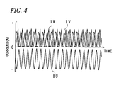
- Fig. 4 shows changes of the phase currents shown in Fig. 3 .
- phase currents flow based on the back electromotive force generated in the electric motor 101.
- a direction of phase currents from the inverter 201 to the electric motor 101 is referred to as positive
- a direction of phase currents from the electric motor 101 to the inverter 201 is referred to as negative.
- a U-phase current IU based on the back electromotive force flows to this switch unit 5b, and a V-phase current IV and a W-phase current IW whose phases are offset through 120 degrees to positive and negative sides, respectively, with respect to the U-phase current IU flow to reflux diodes 4b of the switch units 5b of the other phases.
- a DC component of the U-phase current is offset to an opposite polarity to those of respective DC components of the V-phase current IV and the W-phase current IW.
- the inverter ECU 301 of this embodiment detects a short-circuit failure of the inverter 201 based on respective characteristics of the phase currents. Signals indicating phase currents detected by the phase current sensor 401 are sent to the inverter ECU 301.
- the DC components acquiring unit 501 of the inverter ECU 301 acquires respective DC component values of the phase currents. DC components of the phase currents are obtained by calculating a mean value, an effective value or a center value of the phase currents by the inverter ECU 301 or treating the phase currents with a low-pass filter.
- the short-circuiting determination unit 503 of the inverter ECU 301 determines that the inverter 201 short-circuits and fails when at least one of the DC component values exceeds a threshold Ith in absolute value.
- the phase short-circuiting control unit 505 of the inverter ECU 301 controls all the switching elements provided on either of the positive side or the negative side of the respective arms and off controls all the switching elements provided on the opposite side.
- Fig. 6 shows flow lines of the phase currents when all the switching elements 3a on the positive side of the respective arms are on controlled with the switch unit 5b on the negative side of the U phase short-circuits and fails. Since the on-controlled switching elements are energized, the electric motor 101 is put in a three-phase short-circuited state.
- the inverter ECU 301 maintains this state. No great current flows to the switch unit which short-circuits and fails even thereafter.
- the current flowing through the switching elements 3a and 3b of any of the phases depends on the amount of electric charge of a smoothing capacitor C.
- the rotational speed of the electric motor 101 which is rotated by the internal combustion engine 107 increases, the amount of electric charge accumulated in the smoothing capacitor C also increases.
- Fig. 7 shows flow lines of phase currents when all the switching elements 3b on the negative side are on controlled with the switch unit 5b on the negative side of the U phase shirt-circuiting and failing. The inverter ECU 301 maintains this state.
- a current detection unit Se may be provided between all switch units 5b provided on a negative side and a smoothing capacitor C. As this occurs, when a current detected by the electric current detection unit Se is equal to or smaller than the threshold when the three-phase short-circuiting control unit 505 of the inverter ECU 301 on controls all switching elements on either of the positive side and the negative side of an inverter 203, the inverter ECU 301 maintains that state.
- the three-phase short-circuiting control unit 505 of the inverter ECU 301 off controls all the switching elements of the on-controlled side and on controls all the switching elements of the off-controlled side.
- switching element having a current detection function are used as switching elements 3a and 3b of each phase, in place of the current detection units Seu, Sev, Sew or the current detection unit Se, the respective current detection functions of the switching elements may be made used.
- Fig. 10 is a block diagram showing a system for driving the electric motor 101 which includes an inverter ECU 303 having a short-circuiting side determination unit 507 for determining whether the short-circuited switch unit lies on the positive side or the negative side.
- signals indicating phase currents detected by the phase current sensor 401 are sent to the inverter ECU 303.
- the short-circuiting side determination unit 507 determines a side where the short-circuit failure of the switch unit occurs based on respective polarities of phase current values.
- the short-circuiting side determination unit 507 of the inverter ECU 303 determines the side where the short-circuit failure of the switch unit occurs, three-phase short-circuiting control unit 505 of the inverter ECU 303 on controls the switching elements provided on the side where the short-circuit failure of the switch unit occurs and off controls the switching elements provided on the opposite side. As this occurs, no great current flows to the switch unit which short-circuits and fails. In this case, the three-phase short-circuiting control unit 505 of the inverter ECU 303 does not have to switch on/off controls of the switching elements based on the currents detected by the current detection units Seu, Sev, Sew or Se.
- the inverter ECU 301, 303 detects the short-circuit failure based on the signals from the phase current sensor 401. Further, the inverter ECU 301, 303 on/off controls the switching elements of the inverter 201, 203 so that the three-phase short-circuited state is generated in the electric motor 101 without allowing a great current to flow to the switch unit which short-circuits and fails. In this way, according to the embodiment, even though the control of the electric motor 101 is stopped, the three-phase short-circuiting control can be performed by detecting the short-circuit failure of the inverter 201, 203.
- the inverter ECUs 301, 303 of the first embodiment may not be able to detect the short-circuit failure of the inverters 201, 203 accurately. For example, when a failure occurs in the phase current sensor 401 in which phase currents detected by the phase current sensor 401 stay at larger values than the threshold Ith shown in Fig. 4 , the inverter ECUs 301, 303 erroneously determines that a short-circuit failure is occurring in the inverters 201, 203.
- the inverter ECUs 301, 303 of the above-described first embodiment determine that the inverters 201, 203 short-circuit and fail when at least one of the DC components of the three phase currents exceeds the threshold Ith in absolute value.
- an inverter ECU 305 of a second embodiment determines that the inverters 201, 203 short-circuit and fail by verifying to which of cases below the result of a comparison of the DC components of the three phase currents with the threshold Ith corresponds.
- the inverter ECU 305 determines that the phase current sensor 401 functions normal and the short-circuit failure is occurring in the inverters 201, 203. Thereafter, as in the first embodiment, the inverter ECU 305 executes the three-phase short-circuiting control on the electric motor 101.
- the inverter ECU 305 determines that the short-circuit failure is occurring in the inverters 201, 203. As this occurs, the inverter ECU 305 determines that although the short-circuit failure is occurring in the inverters 201, 203, one of the three values is equal to or smaller than the threshold Ith in absolute value due to one of the sensors making up the phase current sensor 401 failing. In addition, in such a case, although there is a possibility that two of the three sensors making up the phase current sensor 401 fail, determining that the short-circuit failure is occurring in the inverters 201, 203, the inverter ECU 305 executes the three-phase short-circuiting control on the electric motor 101.
- the inverter ECU 305 determines that no short-circuit failure is occurring in the inverters 201, 203. As this occurs, the inverter ECU 305 determines that one of the three values exceeds the threshold Ith in absolute value due to one of the sensors making up the phase current sensor 401 failing.
- the inverter ECU 305 of this embodiment determines whether or not the inverters 201, 203 short-circuit and fail in view of the conditions of the phase current sensor 401, and therefore, the inverter ECU 305 can detect the short-circuit failure of the inverters 201, 203 more accurately.
- the rotor of the electric motor 101 is connected directly to the drive shaft of the internal combustion engine 107.
- the invention may be applied to a vehicle as shown in Fig. 13 in which a drive shaft of an internal combustion engine 107 is connected to a gearbox 109 and a drive shaft 151 via a clutch 113 and a drive shaft of an electric motor 101 is connected to the gearbox 109 and the drive shaft 151 without interposing the clutch therebetween.
Landscapes
- Engineering & Computer Science (AREA)
- Power Engineering (AREA)
- Transportation (AREA)
- Mechanical Engineering (AREA)
- Life Sciences & Earth Sciences (AREA)
- Sustainable Development (AREA)
- Sustainable Energy (AREA)
- Inverter Devices (AREA)
- Control Of Ac Motors In General (AREA)
- Electric Propulsion And Braking For Vehicles (AREA)
- Control Of Electric Motors In General (AREA)
- Hybrid Electric Vehicles (AREA)
Abstract
Description
- The present invention relates to a control system for an electric motor to which electric power is supplied from a DC power supply via a multi-phase inverter in which a switch unit including a switching element and a reflux diode connected in parallel to the switching element is provided on each of a positive side and a negative side of each of arms of respective phases.
- An HEV (Hybrid Electrical Vehicle) runs on driving force from an internal combustion engine and/or an electric motor.
Fig. 14 is a block diagram of an internal configuration of the HEV. In the HEV (hereinafter, referred to simply as the "vehicle") shown inFig. 14 , driving force from an internal combustion engine (ENG) 107 and/or an electric motor (MOT) 101 is transmitted to drivewheels 153 via agearbox 109 and adrive shaft 151. In the vehicle shown inFig. 14 , a rotor of theelectric motor 101 is connected directly to a drive shaft of theinternal combustion engine 107. Thus, when theinternal combustion engine 107 runs, the rotor of theelectric motor 101 also rotates. - The
internal combustion engine 107 generates a driving force (an output torque) to run the vehicle. An engine ECU (ENG ECU) 117 controls theinternal combustion engine 107. Theelectric motor 101 is a three-phase AC motor, for example, and generates a driving force (an output torque) to run the vehicle. A motor ECU (MOT ECU) 119 controls theelectric motor 101. A battery (BATT) 103 is a DC power supply and supplies electric power to theelectric motor 101 via aninverter 105. The output voltage of thebattery 103 is a high voltage (for example, 100 to 200V). Theinverter 105 converts a DC current from thebattery 103 into three phase AC currents. An inverter ECU (INV ECU) 111 controls theinverter 105. - A
clutch 113 interrupts or connects a transmission line of driving force from theinternal engine 107 and/or theelectric motor 101 to thedrive wheels 153 based on an instruction from amanagement ECU 115. When theclutch 113 is disengaged, the driving force is not transmitted to thedrive wheels 153, but theclutch 113 is engaged, the drive force is transmitted to thedrive wheel 153. Thegearbox 109 is a transmission which converts the driving force from theinternal combustion engine 107 and/or theelectric motor 101 into a rotational speed and torque at desirable gear ratios for transmission to thedrive shaft 151. - The management ECU (MG ECU) 115 controls the
internal combustion engine 107, theelectric motor 101 and theinverter 105, instructs theclutch 113 to be engaged or disengaged and instructs thegearbox 109 to change the gear ratios thereof. -
Fig. 15 is a block diagram of a driving system installed in the vehicle shown inFig. 14 for driving theelectric motor 101. As shown inFig. 15 , in theinverter 105,arms electric motor 101, and thearms power supply terminals respective arms electric motor 101, respectively. - A switch unit includes a switching element such as IBGT or MOSFET and a reflux diode connected in parallel to the switching element. Such switch unit is provided on each of a positive side and a negative side on each of the respective arums. For example, for each of the respective arms, a
switch unit 5a including aswitching element 3a and areflux diode 4a is provided on a positive side, and aswitch unit 5b including aswitching element 3b and areflux diode 4b is provided on a negative side. On each arm, a collector of the positive-side switching element 3a and a cathode of the positive-side reflux diode 4a are connected to the positive-sidepower supply terminal 2a, and an emitter of the negative-side switching element 3b and an anode of the negative-side reflux diode 4b are connected to the negative-sidepower supply terminal 2b. A positive terminal of thebattery 103 is connected to the positive-sidepower supply terminal 2a via a contactor SW. - Each switching element is on/off controlled by a control signal from the
inverter ECU 111. A gate resistor R is connected to a gate terminal of each switching element, and a control signal from the inverter ECU 111 is inputted into the gate terminal via the gate resistor R. - When a failure is generated in which the resistance value of the gate resistor R is increased, the switching speed of the switching element becomes slow, and the switching loss is increased, whereby the temperature of the switching element is increased. As a result, a thermal runaway occurs in the switching element which may result in a short-circuit failure. Further, when the
inverter 105 including the short-circuited switching element is continuously used, a greater current than the normal current flows, and therefore, theelectric motor 101 or three-phase wires may fail. Consequently, in Patent Document 1, in order to prevent the occurrence of malfunction or trouble in theelectric motor 101 or three-phase wires when a short-circuit failure occurs in theinverter 105, a greater current is prevented from flowing to theinverter 105. - For example, in Patent Document 1, when the switching element of the
switching portion 5b to which a U-phase current flows short-circuits to fail, theinverter ECU 111 on controls the switching elements of the switchingportions 5b which are provided on the negative side and off controls the switching elements of theswitch units 5a which are provided on the positive side. Consequently, there is produced a state in which inverter 105 side ends of the armatures Au, Av, Aw of the respective phases of theelectric motor 101 are substantially short-circuited relative to each other. Hereinafter, this state will be referred to as a "three-phase short-circuited state." And, a control to generate the three-phase short-circuited state in theelectric motor 101 will be referred to as a "three-phase short-circuiting control."Fig. 16 shows examples of waveforms of the respective phases which are generated when the rotor of theelectric motor 101 which is in the three-phase short-circuited state is rotated by driving theinternal combustion engine 107. - Patent Document 1:
JP-2008-220045-A - When the
electric motor 101 runs, the inverter ECU 222 PWM controls theinverter 105 so that the twoswitching elements switch units electric motor 101 is in operation, electric power is supplied from thebattery 103 and is received by theelectric motor 101. Consequently, a great current (a short-circuit current) flows to both theswitch units electric motor 101, when the positive-side switch unit 5a and the negative-side switch unit 5b of the arm corresponding to any of the phases of theinverter 105 are energized simultaneously, the short-circuit failure of theinverter 105 is detected. - In the vehicle shown in
Fig. 14 , the motor ECU 119 may not control theelectric motor 101 at all when the vehicle runs only on the driving force from theinternal combustion engine 107. As this occurs, theinverter ECU 111 off controls all the switching elements and opens the contactor SW provided between thebattery 103 and the positive-sidepower supply terminal 2a. In this state, both theswitch units inverter 105 is not detected by the short-circuit detection function possessed by Patent Document 1. When he short-circuit failure is not detected although theinverter 105 is failed due to short-circuit, theinverter ECU 111 does not execute the three-phase short-circuiting control, and therefore, a malfunction or failure is eventually generated in theelectric motor 101 or the three-phase wires. - An object of the invention is to provide a control system for an electric motor which can detect a short-circuit failure of the inverter even when the control of the electric motor is stopped.
- Claim 1 provides a control system for an electric motor (for example, an
electric motor 101 in an embodiment) to which electric power is supplied from a DC power supply (for example, abattery 103 in the embodiment) via a multi-phase inverter (for example, aninverters switch units arms elements reflux diodes - a phase current detection unit (for example, a phase
current sensor 401 in the embodiment) for detecting phase currents which flow between the inverter and the electric motor; - a DC component acquiring unit (for example, a DC
component acquiring unit 501 in the embodiment) for acquiring DC components of the respective phase currents; and - a short-circuiting determination unit (for example, a short-
circuiting determination unit 503 in the embodiment) for determining that a short-circuit failure occurs in the inverter when at least one of the DC components of the phase currents acquired by the DC component acquiring unit exceeds a threshold. - Claim 2 provides the system, based on Claim 1, further comprising:
- a switch control unit (for example, a three-phase short-circuiting control unit 505) for on controlling all of switching elements provided on either of the positive side and the negative side and off controlling all of switching elements provided on the opposite side, among the switching elements included in the inverter.
- Claim 3 provides the system, based on Claim 2, further comprising:
- a current detection unit (for example, current detection units Seu, Sev, Sew, Se in the embodiment) for detecting a current which flows to the two switching elements provided on the positive side and the negative side of each phase,
- wherein, when a current value detected by the current detection unit is equal to or larger than a threshold, the switch control unit off controls all the switching elements of the on-controlled side and on controls all the switching elements of the off-controlled side.
-
Claim 4 provides the system, based on Claim 2, further comprising: - a short-circuiting side determination unit (for example, a short-circuiting
side determination unit 507 in the embodiment) for determining a side where the short-circuit failure of the switch unit occurs based on polarities of phase currents by a back electromotive force generated in the electric motor when all the switching elements included in the inverter are off controlled, - wherein the switch control unit on controls all the switching elements provided on the side determined by the short-circuiting side determination unit and off controls all the switching elements provided on the opposite side.
-
Claim 5 provides a control system for an electric motor (for example, anelectric motor 101 in an embodiment) to which electric power is supplied from a DC power supply (for example, abattery 103 in the embodiment) via a three-phase inverter (for example, aninverters switch units arms elements reflux diodes - a phase current detection unit (for example, a phase
current sensor 401 in the embodiment) including three sensors for detecting phase currents which flow between the inverter and the electric motor; - a DC component acquiring unit (for example, a DC
component acquiring unit 501 in the embodiment) for acquiring DC components of the respective phase currents and - a short-circuiting determination unit (for example, a short-circuiting
determination unit 503 in the embodiment) for determining that a short-circuit failure occurs in the inverter when at least two of the DC components of the three phase currents acquired by the DC component acquiring unit exceeds a threshold. - Claim 6 provides the system, based on
Claim 5,
wherein the short-circuiting determination unit determines that the short-circuit failure occurs in the inverter when all the DC components of the three phase currents exceed the threshold, and determines not only that the short-circuit failure occurs in the inverter but also that one of the sensors making up the phase current detection unit fails when two of the DC components of the three phase currents exceed the threshold. - Claim 7 provides the system, based on
Claim 5, further comprising: - a switch control unit for on controlling all of switching elements provided on either of the positive side and the negative side and off controlling all of switching elements provided on the opposite side, among the switching elements included in the inverter.
- Claim 8 provides the system, based on Claim 7, further comprising:
- a current detection unit for detecting a current which flows to the two switching elements provided on the positive side and the negative side of each phase,
- wherein, when a current value detected by the current detection unit is equal to or larger than a threshold, the switch control unit off controls all the switching elements of the on-controlled side and on controls all the switching elements of the off-controlled side.
- According to the electric motor control systems of Claims 1 to 8, the short-circuit failure of the inverter can be detected even though the control of the electric motor is stopped.
- According to the electric motor control systems of Claims 2 to 4 and 7 to 8, the electric motor can be controlled based on three-phase short-circuiting control.
- According to the electric motor control systems of
Claims 3, 4 and 8, the electric motor can be controlled based on three-phase short-circuiting control while preventing a great current from flowing to the switch unit which short-circuits and fails. - According to the electric motor control system of Claim 6, the short-circuit failure of the inverter can be detected in an ensured fashion.
-
-
Fig. 1 is a block diagram showing an internal configuration of an HEV equipped with an electric motor control system according to the invention. -
Fig. 2 is a block diagram showing a system for driving anelectric motor 101 provided in the vehicle shown inFig.1 -
Fig. 3 shows flow lines, directions and magnitudes of respective phase currents which flow in aninverter 201 when aswitch unit 5b provided on a negative side of anarm 1u short-circuits and fails while a back electromotive force is being generated in theelectric motor 101. -
Fig. 4 shows changes of phase currents shown inFig. 3 . -
Fig. 5 shows changes of the phase currents shown inFig. 3 and DC components of the phase currents. -
Fig. 6 shows flow lines of the phase currents when all switchingelements 3a on a positive side are on controlled with aswitch unit 5b on a negative side of a U phase short-circuiting and failing. -
Fig. 7 shows flow lines of the phase currents when all switchingelements 3b on negative side are on controlled, on the contrary toFig. 6 , with theswitch unit 5b on the negative side of the U phase short-circuiting and failing. -
Fig. 8 shows phase currents flowing when aninverter ECU 301 executes the three-phase short-circuiting control when theinverter 201 short-circuits and fails. -
Fig. 9 is a block diagram of a system for driving theelectric motor 101 which includes aninverter 203 of another form. -
Fig. 10 is a block diagram of a system for driving theelectric motor 101 which includes aninverter 303 of other form. -
Fig. 11 shows flow lines, directions and magnitudes of respective phase currents which flow in theinverter 201 when aswitch unit 5a provided on the positive side of thearm 1u short-circuits and fails while a back electromotive force is being generated in theelectric motor 101. -
Fig. 12 shows a phase current when a phasecurrent sensor 401 fails. -
Fig. 13 is a block diagram showing an internal configuration of an HEV of another form. -
Fig. 14 is a block diagram showing an internal configuration of an HEV. -
Fig. 15 is a block diagram showing a system for driving anelectric motor 101 provided in the vehicle shown inFig. 14 . -
Fig. 16 shows examples of waveforms of phase currents generated when a rotor of anelectric motor 101 which is in a three-phase short-circuited state is driven by aninternal combustion engine 107. - Hereinafter, embodiment of the invention will be described by reference to the drawings.
- An HEV (Hybrid Electrical Vehicle) runs on driving force of an internal combustion engine and/or an electric motor.
-
Fig. 1 is a block diagram showing an internal configuration of an HEV equipped with an electric motor control system according to the invention. An HEV (hereinafter, referred to simply as a "vehicle") shown inFig. 1 includes an electric motor (MOT) 101, a battery (BATT) 103, an inverter (INV) 201, an internal combustion engine (ENG) 107, a management ECU (MG ECU) 115, an engine ECU (ENG ECU) 301, a phasecurrent sensor 401, a clutch 113, agearbox 109, adrive shaft 151, and drivewheels 153. The constituent elements other than theinverter 201, theinverter ECU 301 and the phasecurrent sensor 401 are the same as the corresponding constituent elements in the vehicle shown inFig. 14 . Thus, inFig. 1 , like reference numerals are given to the constituent elements common to those shown inFig. 14 . - In the vehicle shown in
Fig. 1 , as the vehicle shown inFig. 14 , a driving force from theinternal combustion engine 107 and/or theelectric motor 101 is transmitted to thedrive wheels 153 via thegearbox 109 and thedrive shaft 151. In addition, in the vehicle shown inFig. 1 , a rotor of theelectric motor 101 is connected directly to a drive shaft of theinternal combustion engine 107. Thus, when theinternal combustion engine 107 runs, the rotor of theelectric motor 101 also rotates. -
Fig. 2 is a block diagram showing a system installed in the vehicle for driving theelectric motor 101. Theelectric motor 101 is a three-phase AC motor, for example. Thebattery 103 is a DC power supply and supplies electric power to theelectric motor 101 via theinverter 201. An output voltage of thebattery 103 is a high voltage (for example, 100 to 200V). Theinverter 201 converts a DC current from thebattery 103 into three-phase AC currents. Theinverter 201 has current detection units Seu, Sev, Sew for detecting currents flowing to switchingelements power supply terminal 2b andrespective switch units 5b of the phases. Signal indicating currents detected by the current detection units Seu, Sev, Sew are sent to theinverter ECU 301. - The
inverter ECU 301 controls theinverter 201. As shown inFig. 2 , theinverter ECU 301 of this embodiment has a DCcomponent acquiring unit 501, a short-circuitingdetermination unit 503 and a three-phase short-circuiting control unit 505. Respective operations of these constituent units will be described in detail later. The phasecurrent sensor 401 includes three sensors for detecting respective phase currents of theelectric motor 101. Signals indicating respective phase currents detected by the phasecurrent sensor 401 are sent to theinverter ECU 301. The other constituent elements than the current detection units Seu, Sev, Sew of theinverter 201 shown inFig. 2 , theinverter ECU 301 and the phasecurrent sensor 401 are similar to the corresponding constituent elements shownFig. 15 . Consequently, also inFig. 2 , like reference numerals are given to the constituent elements which are like to those shown inFig. 15 . - Hereinafter, the control of the
inverter 201 by theinverter ECU 301 of this embodiment will be described by reference toFig. 2 . When theelectric motor 101, which is controlled by themotor ECU 119, is in operation, theinverter ECU 301 PWM controls theinverter 201 so that the twoswitching elements electric motor 101 is in operation, electric power is supplied from thebattery 103 and is received by theelectric motor 101. On the other hand, when the control of theelectric motor 101 by themotor ECU 119 is not performed at all, theinverter ECU 301 off controls all of switching elements of theinverter 201 and opens a contactor SW. - Next, phase currents (a U-phase current, a V-phase current, a W-phase current) of the
electric motor 101 will be described which flow therein when the vehicle shown inFig. 1 runs only on driving force from theinternal combustion engine 107 and the control of theelectric motor 101 is not performed at all. As described above, since the rotor of theelectric motor 101 is connected directly to the drive shaft of theinternal combustion engine 107, when theinternal combustion engine 107 runs, the rotor of theelectricmotor 101 also rotates. As this occurs, a back electromotive force is generated in theelectric motor 101. - When the
inverter 201 is in a normal state, all of the switching elements of theinverter 201 are controlled to be off by theinverter ECU 301. Consequently, even when a back electromotive force is generated in theelectric motor 101 by running theinternal combustion engine 107, the phase currents of theelectric motor 101 are substantially 0. - On the other hand, when the
inverter 201 short-circuits and fails, the phase currents of theelectric motor 101 are not substantially 0.Fig. 3 shows flow lines, directions and magnitudes of phase currents flowing at a certain moment in theinverter 201 when theswitch unit 5b provided on the negative side of thearm 1u short-circuits and fails while the back electromotive force is being generated in theelectric motor 101. In addition,Fig. 4 shows changes of the phase currents shown inFig. 3 . When the switch unit short-circuits and fails, phase currents flow based on the back electromotive force generated in theelectric motor 101. Here, a direction of phase currents from theinverter 201 to theelectric motor 101 is referred to as positive, and a direction of phase currents from theelectric motor 101 to theinverter 201 is referred to as negative. - As shown in
Figs. 3 and4 , when theswitch unit 5b provided on the negative side of thearm 1u short-circuits and fails, a U-phase current IU based on the back electromotive force flows to thisswitch unit 5b, and a V-phase current IV and a W-phase current IW whose phases are offset through 120 degrees to positive and negative sides, respectively, with respect to the U-phase current IU flow to refluxdiodes 4b of theswitch units 5b of the other phases. As shown inFig. 4 , a DC component of the U-phase current is offset to an opposite polarity to those of respective DC components of the V-phase current IV and the W-phase current IW. - The
inverter ECU 301 of this embodiment detects a short-circuit failure of theinverter 201 based on respective characteristics of the phase currents. Signals indicating phase currents detected by the phasecurrent sensor 401 are sent to theinverter ECU 301. The DCcomponents acquiring unit 501 of theinverter ECU 301 acquires respective DC component values of the phase currents. DC components of the phase currents are obtained by calculating a mean value, an effective value or a center value of the phase currents by theinverter ECU 301 or treating the phase currents with a low-pass filter. As shown inFig. 5 , the short-circuitingdetermination unit 503 of theinverter ECU 301 determines that theinverter 201 short-circuits and fails when at least one of the DC component values exceeds a threshold Ith in absolute value. - After the
inverter ECU 301 detects the short-circuit failure of theinverter 201, the phase short-circuiting control unit 505 of theinverter ECU 301 on controls all the switching elements provided on either of the positive side or the negative side of the respective arms and off controls all the switching elements provided on the opposite side.Fig. 6 shows flow lines of the phase currents when all theswitching elements 3a on the positive side of the respective arms are on controlled with theswitch unit 5b on the negative side of the U phase short-circuits and fails. Since the on-controlled switching elements are energized, theelectric motor 101 is put in a three-phase short-circuited state. As a result, when all the currents detected by the current detection units Seu, Sev, Sew of theinverter 201 are equal to or smaller than the threshold, theinverter ECU 301 maintains this state. No great current flows to the switch unit which short-circuits and fails even thereafter. - When the
inverter ECU 301 executes the above control, the current flowing through theswitching elements electric motor 101 which is rotated by theinternal combustion engine 107 increases, the amount of electric charge accumulated in the smoothing capacitor C also increases. - As a result of the above control, when even any one of the currents detected by the current detection units Seu, Sev, Sew exceeds the threshold, the three-phase short-
circuiting control unit 505 of theinverter ECU 301 off controls all the switching elements of the on-controlled side and on controls all the switching elements of the off-controlled side. Contrary toFig. 6 ,Fig. 7 shows flow lines of phase currents when all theswitching elements 3b on the negative side are on controlled with theswitch unit 5b on the negative side of the U phase shirt-circuiting and failing. Theinverter ECU 301 maintains this state. - By the
inverter ECU 301 executing the three-phase short-circuiting control described above after the detection of the short-circuit failure of theinverter 201 by theinverter ECU 301, all the phase currents take waveforms centered at 0A as shown inFig. 8 . - In place of the current detection units Seu, Sev, Sew, as shown in
Fig. 9 , a current detection unit Se may be provided between allswitch units 5b provided on a negative side and a smoothing capacitor C. As this occurs, when a current detected by the electric current detection unit Se is equal to or smaller than the threshold when the three-phase short-circuiting control unit 505 of theinverter ECU 301 on controls all switching elements on either of the positive side and the negative side of aninverter 203, theinverter ECU 301 maintains that state. However, when the electric current detected by the electric current detection unit Se exceeds the threshold, as described before, the three-phase short-circuiting control unit 505 of theinverter ECU 301 off controls all the switching elements of the on-controlled side and on controls all the switching elements of the off-controlled side. - When switching element having a current detection function are used as switching
elements - When detecting a shirt-circuit failure of the
inverters Fig. 10 is a block diagram showing a system for driving theelectric motor 101 which includes aninverter ECU 303 having a short-circuitingside determination unit 507 for determining whether the short-circuited switch unit lies on the positive side or the negative side. As described above, signals indicating phase currents detected by the phasecurrent sensor 401 are sent to theinverter ECU 303. The short-circuitingside determination unit 507 determines a side where the short-circuit failure of the switch unit occurs based on respective polarities of phase current values. - When the switch unit on the negative side short-circuits and fails, as shown in
Figs. 3 to 5 , in the three phase currents, the two phase currents (V-phase current and W-phase current) take positive values, while the remaining one phase current (U-phase current) takes a negative value. On the contrary, when the switch unit on the positive side short-circuits and fails, as shown inFig. 11 , in the three phase currents, the two phase currents (V-phase current and W-phase current) takes negative values, while the remaining one phase current (U-phase current) takes a positive value. Consequently, the short-circuitingside determination unit 507 of theinverter ECU 303 determines the side where the short-circuit failure of the switch unit occurs based on whether the two phase currents having the same polarity take the positive or negative values. - When the short-circuiting
side determination unit 507 of theinverter ECU 303 determines the side where the short-circuit failure of the switch unit occurs, three-phase short-circuiting control unit 505 of theinverter ECU 303 on controls the switching elements provided on the side where the short-circuit failure of the switch unit occurs and off controls the switching elements provided on the opposite side. As this occurs, no great current flows to the switch unit which short-circuits and fails. In this case, the three-phase short-circuiting control unit 505 of theinverter ECU 303 does not have to switch on/off controls of the switching elements based on the currents detected by the current detection units Seu, Sev, Sew or Se. - As described heretofore, according to the embodiment, when the vehicle runs only on the driving force from the
internal combustion engine 107 and the control of theelectric motor 101 is not performed at all, when theinverter inverter ECU current sensor 401. Further, theinverter ECU inverter electric motor 101 without allowing a great current to flow to the switch unit which short-circuits and fails. In this way, according to the embodiment, even though the control of theelectric motor 101 is stopped, the three-phase short-circuiting control can be performed by detecting the short-circuit failure of theinverter - When the phase
current sensor 401 fails, theinverter ECUs inverters current sensor 401 in which phase currents detected by the phasecurrent sensor 401 stay at larger values than the threshold Ith shown inFig. 4 , theinverter ECUs inverters - The
inverter ECUs inverters inverters -
- Case 1: All the DC components of the three phase currents exceed the threshold Ith in absolute value.
- Case 2: Among the DC components of the three phase currents, two exceed the threshold Ith in absolute value, while the remaining one is equal to or smaller than the threshold Ith.
- Case 3: Among the DC components of the three phase currents, one exceeds the threshold Ith in absolute value, while the remaining two are equal to or smaller than the threshold Ith.
- When the comparison result corresponds to Case 1, the inverter ECU 305 determines that the phase
current sensor 401 functions normal and the short-circuit failure is occurring in theinverters electric motor 101. - When the comparison result corresponds to Case 2, the inverter ECU 305 determines that the short-circuit failure is occurring in the
inverters inverters current sensor 401 failing. In addition, in such a case, although there is a possibility that two of the three sensors making up the phasecurrent sensor 401 fail, determining that the short-circuit failure is occurring in theinverters electric motor 101. - When the comparison result corresponds to Case 3, the inverter ECU 305 determines that no short-circuit failure is occurring in the
inverters current sensor 401 failing. - The inverter ECU 305 of this embodiment determines whether or not the
inverters current sensor 401, and therefore, the inverter ECU 305 can detect the short-circuit failure of theinverters - In the vehicle of the embodiment shown in
Fig. 1 , the rotor of theelectric motor 101 is connected directly to the drive shaft of theinternal combustion engine 107. However, the invention may be applied to a vehicle as shown inFig. 13 in which a drive shaft of aninternal combustion engine 107 is connected to agearbox 109 and adrive shaft 151 via a clutch 113 and a drive shaft of anelectric motor 101 is connected to thegearbox 109 and thedrive shaft 151 without interposing the clutch therebetween. - While the specific embodiments are exemplified, the skilled person in the art can variously alter or modify these embodiments without departing from the spirit and scope of the invention.
- This patent application is based on Japanese Patent Application No.
2008-333639 filed on December 26, 2008 - 101 Electric motor (MOT); 103 Battery (BAT); 107 Internal combustion engine (ENG); 109 Gearbox; 113 Clutch; 115 Management ECU (MG ECU); 117 Engine ECU (ENG ECU); 119 Motor ECU (MOT ECU); 151 Drive shaft; 153 Drive wheel; 201, 203 Inverter (INV) ; 301, 303, 305 Inverter ECU (INV ECU) ; 401 Phase current sensor; 501 DC component acquiring unit; 503 Short-circuiting determination unit; 505 Three-phase short-circuiting control unit; 507 Short-circuiting side determination unit; SW Contactor; C Smoothing capacitor; 1u, 1v, 1w Arm; 3a, 3b Switching element; 4a, 4b Reflux diode; 5a, 5 Switch unit; Seu, Sev, Sew Current detection unit.
Claims (8)
- A control system for an electric motor to which electric power is supplied from a DC power supply via a multi-phase inverter, the multi-phase inverter including switch units respectively provided on a positive side and a negative side of arms corresponding to respective phases, each switch unit including a switching element and a reflux diode connected in parallel thereto, comprising:a phase current detection unit for detecting phase currents which flow between the inverter and the electric motor;a DC component acquiring unit for acquiring DC components of the respective phase currents; anda short-circuiting determination unit for determining that a short-circuit failure occurs in the inverter when at least one of the DC components of the phase currents acquired by the DC component acquiring unit exceeds a threshold.
- The system of Claim 1, further comprising:a switch control unit for on controlling all of switching elements provided on either of the positive side and the negative side and off controlling all of switching elements provided on the opposite side, among the switching elements included in the inverter.
- The system of Claim 2, further comprising:a current detection unit for detecting a current which flows to the two switching elements provided on the positive side and the negative side of each phase,wherein, when a current value detected by the current detection unit is equal to or larger than a threshold, the switch control unit off controls all the switching elements of the on-controlled side and on controls all the switching elements of the off-controlled side.
- The system of Claim 2, further comprising:a short-circuiting side determination unit for determining a side where the short-circuit failure of the switch unit occurs based on polarities of phase currents by a back electromotive force generated in the electric motor when all the switching elements included in the inverter are off controlled,wherein the switch control unit on controls all the switching elements provided on the side determined by the short-circuiting side determination unit and off controls all the switching elements provided on the opposite side.
- A control system for an electric motor to which electric power is supplied from a DC power supply via a three-phase inverter, the three-phase inverter including switch units respectively provided on a positive side and a negative side of arms corresponding to respective phases, each switch unit including a switching element and a reflux diode connected in parallel thereto, comprising:a phase current detection unit including three sensors for detecting phase currents which flow between the inverter and the electric motor;a DC component acquiring unit for acquiring DC components of the respective phase currents; anda short-circuiting determination unit for determining that a short-circuit failure occurs in the inverter when at least two of the DC components of the three phase currents acquired by the DC component acquiring unit exceeds a threshold.
- The system of Claim 5,
wherein the short-circuiting determination unit determines that the short-circuit failure occurs in the inverter when all the DC components of the three phase currents exceed the threshold, and determines not only that the short-circuit failure occurs in the inverter but also that one of the sensors making up the phase current detection unit fails when two of the DC components of the three phase currents exceed the threshold. - The system of Claim 5, further comprising:a switch control unit for on controlling all of switching elements provided on either of the positive side and the negative side and off controlling all of switching elements provided on the opposite side, among the switching elements included in the inverter.
- The system of Claim 7, further comprising:a current detection unit for detecting a current which flows to the two switching elements provided on the positive side and the negative side of each phase,wherein, when a current value detected by the current detection unit is equal to or larger than a threshold, the switch control unit off controls all the switching elements of the on-controlled side and on controls all the switching elements of the off-controlled side.
Priority Applications (1)
| Application Number | Priority Date | Filing Date | Title |
|---|---|---|---|
| EP12187918.3A EP2546980B1 (en) | 2008-12-26 | 2009-11-02 | Electric motor control system |
Applications Claiming Priority (2)
| Application Number | Priority Date | Filing Date | Title |
|---|---|---|---|
| JP2008333639A JP4968698B2 (en) | 2008-12-26 | 2008-12-26 | Electric motor control device |
| PCT/JP2009/068784 WO2010073819A1 (en) | 2008-12-26 | 2009-11-02 | Motor control device |
Related Child Applications (1)
| Application Number | Title | Priority Date | Filing Date |
|---|---|---|---|
| EP12187918.3A Division EP2546980B1 (en) | 2008-12-26 | 2009-11-02 | Electric motor control system |
Publications (2)
| Publication Number | Publication Date |
|---|---|
| EP2372900A1 true EP2372900A1 (en) | 2011-10-05 |
| EP2372900A4 EP2372900A4 (en) | 2012-06-06 |
Family
ID=42287444
Family Applications (2)
| Application Number | Title | Priority Date | Filing Date |
|---|---|---|---|
| EP12187918.3A Not-in-force EP2546980B1 (en) | 2008-12-26 | 2009-11-02 | Electric motor control system |
| EP09834623A Withdrawn EP2372900A4 (en) | 2008-12-26 | 2009-11-02 | Motor control device |
Family Applications Before (1)
| Application Number | Title | Priority Date | Filing Date |
|---|---|---|---|
| EP12187918.3A Not-in-force EP2546980B1 (en) | 2008-12-26 | 2009-11-02 | Electric motor control system |
Country Status (6)
| Country | Link |
|---|---|
| US (1) | US8598826B2 (en) |
| EP (2) | EP2546980B1 (en) |
| JP (1) | JP4968698B2 (en) |
| CN (1) | CN102257724B (en) |
| BR (1) | BRPI0923687A2 (en) |
| WO (1) | WO2010073819A1 (en) |
Cited By (2)
| Publication number | Priority date | Publication date | Assignee | Title |
|---|---|---|---|---|
| EP3128669A4 (en) * | 2014-04-03 | 2017-11-01 | Fuji Electric Co., Ltd. | Safety control device |
| EP3681035A4 (en) * | 2017-09-05 | 2021-04-14 | Hitachi, Ltd. | Ac electric motor monitoring device and monitoring method, and electric motor drive system monitoring device and monitoring method |
Families Citing this family (37)
| Publication number | Priority date | Publication date | Assignee | Title |
|---|---|---|---|---|
| JP5365431B2 (en) * | 2009-09-04 | 2013-12-11 | 三菱電機株式会社 | Elevator control device |
| JP4962583B2 (en) * | 2010-03-11 | 2012-06-27 | 株式会社デンソー | Discharge control device for power conversion system |
| JP5923955B2 (en) * | 2011-12-06 | 2016-05-25 | 株式会社デンソー | Control device for multi-phase rotating machine |
| JP5465269B2 (en) * | 2012-03-29 | 2014-04-09 | 三菱電機株式会社 | Electric motor drive device including failure detection circuit and failure detection method of electric motor drive device |
| CN104106205B (en) * | 2012-03-30 | 2017-05-31 | 富士电机株式会社 | AC motor system and its control method |
| JP5945692B2 (en) * | 2012-07-03 | 2016-07-05 | パナソニックIpマネジメント株式会社 | Inverter device |
| CN103066556B (en) * | 2012-12-04 | 2017-03-29 | 联合汽车电子有限公司 | The over-voltage protection method of high-voltage direct current |
| JP6155708B2 (en) * | 2013-03-08 | 2017-07-05 | 株式会社ジェイテクト | Motor control device |
| JP5876846B2 (en) * | 2013-03-13 | 2016-03-02 | 東芝三菱電機産業システム株式会社 | Electric motor drive |
| FR3005222B1 (en) * | 2013-04-26 | 2015-04-17 | Valeo Sys Controle Moteur Sas | ELECTRONIC ARCHITECTURE FOR CONTROL OF CONTINUOUS / ALTERNATIVE VOLTAGE CONVERTER |
| JP6056734B2 (en) * | 2013-10-25 | 2017-01-11 | トヨタ自動車株式会社 | Vehicle control device |
| US9071187B2 (en) * | 2013-11-06 | 2015-06-30 | GM Global Technology Operations LLC | Method and apparatus for increasing a current sensing range in a polyphase motor system |
| DE102013226560A1 (en) | 2013-12-19 | 2015-06-25 | Robert Bosch Gmbh | Apparatus and method for operating an electrical machine |
| JP5943151B2 (en) * | 2014-03-11 | 2016-06-29 | 日本精工株式会社 | Motor control device, electric power steering device using the same, and vehicle |
| JP6173564B2 (en) * | 2014-03-18 | 2017-08-02 | 日立建機株式会社 | Work machine |
| JP2015223050A (en) * | 2014-05-23 | 2015-12-10 | ファナック株式会社 | Inverter and motor drive device with failure detection function of power line |
| JP6327141B2 (en) * | 2014-12-24 | 2018-05-23 | トヨタ自動車株式会社 | Electric vehicle |
| KR102281672B1 (en) * | 2015-04-02 | 2021-07-27 | 주식회사 만도 | Electronic control apparatus and method for eps |
| JP6237699B2 (en) | 2015-05-25 | 2017-11-29 | トヨタ自動車株式会社 | Anomaly detection device |
| EP3131198B1 (en) * | 2015-08-10 | 2022-06-08 | Goodrich Actuation Systems Limited | Control strategy of a dual lane fault tolerant permanent magnet motor to reduce drag torque under fault condition |
| JP6252569B2 (en) * | 2015-09-10 | 2017-12-27 | トヨタ自動車株式会社 | Hybrid vehicle |
| JP6518604B2 (en) * | 2016-02-24 | 2019-05-22 | 本田技研工業株式会社 | POWER SUPPLY DEVICE, DEVICE, AND CONTROL METHOD |
| JP6461838B2 (en) * | 2016-02-24 | 2019-01-30 | 本田技研工業株式会社 | Power supply device, device and control method |
| JP6642201B2 (en) * | 2016-03-30 | 2020-02-05 | 株式会社デンソー | Motor control device and motor control program |
| JP2017190029A (en) * | 2016-04-12 | 2017-10-19 | トヨタ自動車株式会社 | Hybrid-vehicular control apparatus |
| JP6418196B2 (en) * | 2016-04-15 | 2018-11-07 | トヨタ自動車株式会社 | Electric car |
| JP6230677B1 (en) | 2016-10-20 | 2017-11-15 | 三菱電機株式会社 | Control device and control method for rotating electrical machine |
| JP6610586B2 (en) * | 2017-03-13 | 2019-11-27 | トヨタ自動車株式会社 | Drive device |
| JP6824103B2 (en) * | 2017-04-25 | 2021-02-03 | 三菱電機株式会社 | Power semiconductor devices and power semiconductor drive systems |
| DE102017218189A1 (en) * | 2017-10-12 | 2019-04-18 | Zf Friedrichshafen Ag | Safe condition of an electrical machine |
| JP6947016B2 (en) * | 2017-12-26 | 2021-10-13 | 株式会社デンソー | Electric vehicle |
| JP7006428B2 (en) * | 2018-03-23 | 2022-01-24 | 株式会社デンソー | Motor control device |
| CN112848900B (en) * | 2019-11-26 | 2024-07-05 | 松下汽车电子系统株式会社 | Vehicle driving device |
| TWI721829B (en) * | 2020-03-18 | 2021-03-11 | 李岳翰 | Method for increasing wheel resistance when vehicle is stopped and vehicle resistance increasing device |
| CN112083348B (en) * | 2020-07-24 | 2023-05-23 | 苏州汇川联合动力系统有限公司 | Method, system and storage medium for detecting single-phase to ground short circuit of motor |
| WO2022219733A1 (en) * | 2021-04-14 | 2022-10-20 | 三菱電機株式会社 | Power conversion device |
| JP2023040951A (en) * | 2021-09-10 | 2023-03-23 | 日立Astemo株式会社 | Motor drive device and electric vehicle |
Citations (5)
| Publication number | Priority date | Publication date | Assignee | Title |
|---|---|---|---|---|
| JPH0759384A (en) * | 1993-08-19 | 1995-03-03 | Toshiba Corp | Inverter |
| US6683435B1 (en) * | 2002-06-21 | 2004-01-27 | Ford Motor Company | Electrical machine drive method and system |
| US20070093359A1 (en) * | 2005-10-26 | 2007-04-26 | Mitsubishi Denki Kabushiki Kaisha | Vehicular power control apparatus |
| WO2008001949A1 (en) * | 2006-06-30 | 2008-01-03 | Toyota Jidosha Kabushiki Kaisha | Motor drive device |
| WO2008108159A1 (en) * | 2007-03-05 | 2008-09-12 | Honda Motor Co., Ltd. | Controller for motor, and vehicle |
Family Cites Families (5)
| Publication number | Priority date | Publication date | Assignee | Title |
|---|---|---|---|---|
| US5998880A (en) * | 1997-08-07 | 1999-12-07 | General Electric Company | AC locomotive operation without DC current sensor |
| JP4000866B2 (en) * | 2002-02-22 | 2007-10-31 | アイシン・エィ・ダブリュ株式会社 | Driving power supply device and fail judging method |
| JP2006184160A (en) * | 2004-12-28 | 2006-07-13 | Nissan Motor Co Ltd | Current detection apparatus for three-phase a.c. motor with failure detection function |
| US7276871B2 (en) * | 2005-07-25 | 2007-10-02 | Honeywell International, Inc. | System and method for fault protection for permanent magnet machines |
| JP4784478B2 (en) * | 2006-04-20 | 2011-10-05 | 株式会社デンソー | Control device for multiphase rotating electrical machine |
-
2008
- 2008-12-26 JP JP2008333639A patent/JP4968698B2/en not_active Expired - Fee Related
-
2009
- 2009-11-02 EP EP12187918.3A patent/EP2546980B1/en not_active Not-in-force
- 2009-11-02 EP EP09834623A patent/EP2372900A4/en not_active Withdrawn
- 2009-11-02 BR BRPI0923687-2A patent/BRPI0923687A2/en active Search and Examination
- 2009-11-02 WO PCT/JP2009/068784 patent/WO2010073819A1/en active Application Filing
- 2009-11-02 US US13/139,353 patent/US8598826B2/en active Active
- 2009-11-02 CN CN200980151526.7A patent/CN102257724B/en active Active
Patent Citations (5)
| Publication number | Priority date | Publication date | Assignee | Title |
|---|---|---|---|---|
| JPH0759384A (en) * | 1993-08-19 | 1995-03-03 | Toshiba Corp | Inverter |
| US6683435B1 (en) * | 2002-06-21 | 2004-01-27 | Ford Motor Company | Electrical machine drive method and system |
| US20070093359A1 (en) * | 2005-10-26 | 2007-04-26 | Mitsubishi Denki Kabushiki Kaisha | Vehicular power control apparatus |
| WO2008001949A1 (en) * | 2006-06-30 | 2008-01-03 | Toyota Jidosha Kabushiki Kaisha | Motor drive device |
| WO2008108159A1 (en) * | 2007-03-05 | 2008-09-12 | Honda Motor Co., Ltd. | Controller for motor, and vehicle |
Non-Patent Citations (1)
| Title |
|---|
| See also references of WO2010073819A1 * |
Cited By (2)
| Publication number | Priority date | Publication date | Assignee | Title |
|---|---|---|---|---|
| EP3128669A4 (en) * | 2014-04-03 | 2017-11-01 | Fuji Electric Co., Ltd. | Safety control device |
| EP3681035A4 (en) * | 2017-09-05 | 2021-04-14 | Hitachi, Ltd. | Ac electric motor monitoring device and monitoring method, and electric motor drive system monitoring device and monitoring method |
Also Published As
| Publication number | Publication date |
|---|---|
| JP4968698B2 (en) | 2012-07-04 |
| BRPI0923687A2 (en) | 2020-08-11 |
| JP2010158089A (en) | 2010-07-15 |
| WO2010073819A1 (en) | 2010-07-01 |
| EP2372900A4 (en) | 2012-06-06 |
| EP2546980B1 (en) | 2014-03-19 |
| CN102257724A (en) | 2011-11-23 |
| US20110241589A1 (en) | 2011-10-06 |
| US8598826B2 (en) | 2013-12-03 |
| EP2546980A2 (en) | 2013-01-16 |
| EP2546980A3 (en) | 2013-06-26 |
| CN102257724B (en) | 2014-05-21 |
Similar Documents
| Publication | Publication Date | Title |
|---|---|---|
| US8598826B2 (en) | Electric motor control system | |
| US8045301B2 (en) | Motor drive device | |
| US10110154B2 (en) | Controller and a method to drive an inverter circuit for a permanent-magnet synchronous motor | |
| US8791681B2 (en) | Electric power conversion system | |
| JP4757815B2 (en) | Electric motor control device and vehicle | |
| US6239566B1 (en) | Drive system for a permanently excited electric motor having at least one phase winding | |
| US9054626B2 (en) | Motor control apparatus | |
| CN111108681B (en) | Inverter control device | |
| JP4926222B2 (en) | Control device for vehicle power converter | |
| US11387766B2 (en) | Control circuit for electric power converter | |
| EP3575126A1 (en) | Motor controller | |
| US20090195199A1 (en) | Motor drive device | |
| US10933735B2 (en) | Vehicle | |
| EP3982533A1 (en) | Motor control method and circuit for vehicle, motor drive system, and vehicle | |
| US20050226298A1 (en) | Power conversion device | |
| EP3618259A1 (en) | Circuit for actively performing short-circuit and motor controller | |
| US20150015168A1 (en) | Vehicular driving system | |
| JP2019122238A (en) | Motor control device and control method thereof | |
| JP2019134590A (en) | Inverter controller | |
| US7514906B1 (en) | Automotive rotary electrical apparatus | |
| KR101044234B1 (en) | Method for driving oil pump for plug=in hybrid vehicle | |
| JP6854429B2 (en) | Vehicle drive | |
| JP5269567B2 (en) | Electric motor control device and vehicle | |
| CN111572329A (en) | Vehicle drive device |
Legal Events
| Date | Code | Title | Description |
|---|---|---|---|
| PUAI | Public reference made under article 153(3) epc to a published international application that has entered the european phase |
Free format text: ORIGINAL CODE: 0009012 |
|
| 17P | Request for examination filed |
Effective date: 20110622 |
|
| AK | Designated contracting states |
Kind code of ref document: A1 Designated state(s): AT BE BG CH CY CZ DE DK EE ES FI FR GB GR HR HU IE IS IT LI LT LU LV MC MK MT NL NO PL PT RO SE SI SK SM TR |
|
| RIN1 | Information on inventor provided before grant (corrected) |
Inventor name: DANJO YASUYUKI Inventor name: IMAI NAOKI Inventor name: ANRAKU FUMIO Inventor name: FUJITA YUJI |
|
| DAX | Request for extension of the european patent (deleted) | ||
| A4 | Supplementary search report drawn up and despatched |
Effective date: 20120508 |
|
| RIC1 | Information provided on ipc code assigned before grant |
Ipc: H02P 29/02 20060101ALI20120503BHEP Ipc: B60L 11/14 20060101ALI20120503BHEP Ipc: B60L 3/00 20060101ALI20120503BHEP Ipc: H02P 27/06 20060101AFI20120503BHEP Ipc: H02M 7/48 20070101ALI20120503BHEP |
|
| 17Q | First examination report despatched |
Effective date: 20120612 |
|
| STAA | Information on the status of an ep patent application or granted ep patent |
Free format text: STATUS: THE APPLICATION IS DEEMED TO BE WITHDRAWN |
|
| 18D | Application deemed to be withdrawn |
Effective date: 20130205 |