EP2372886B1 - Linear motor - Google Patents
Linear motor Download PDFInfo
- Publication number
- EP2372886B1 EP2372886B1 EP09834910.3A EP09834910A EP2372886B1 EP 2372886 B1 EP2372886 B1 EP 2372886B1 EP 09834910 A EP09834910 A EP 09834910A EP 2372886 B1 EP2372886 B1 EP 2372886B1
- Authority
- EP
- European Patent Office
- Prior art keywords
- permanent magnet
- magnet row
- linear motor
- coil
- phase coil
- Prior art date
- Legal status (The legal status is an assumption and is not a legal conclusion. Google has not performed a legal analysis and makes no representation as to the accuracy of the status listed.)
- Active
Links
- XEEYBQQBJWHFJM-UHFFFAOYSA-N Iron Chemical group [Fe] XEEYBQQBJWHFJM-UHFFFAOYSA-N 0.000 claims description 13
- 230000004907 flux Effects 0.000 claims description 13
- 230000005284 excitation Effects 0.000 claims description 8
- 230000005415 magnetization Effects 0.000 claims description 8
- 239000013598 vector Substances 0.000 claims description 5
- 230000005540 biological transmission Effects 0.000 claims description 4
- 239000004020 conductor Substances 0.000 claims 1
- 238000000034 method Methods 0.000 description 13
- 238000004804 winding Methods 0.000 description 10
- 239000003990 capacitor Substances 0.000 description 5
- 238000009499 grossing Methods 0.000 description 5
- 230000003287 optical effect Effects 0.000 description 4
- CURLTUGMZLYLDI-UHFFFAOYSA-N Carbon dioxide Chemical compound O=C=O CURLTUGMZLYLDI-UHFFFAOYSA-N 0.000 description 2
- 238000010304 firing Methods 0.000 description 2
- 238000003491 array Methods 0.000 description 1
- 229910002092 carbon dioxide Inorganic materials 0.000 description 1
- 239000001569 carbon dioxide Substances 0.000 description 1
- 238000010586 diagram Methods 0.000 description 1
- 230000000694 effects Effects 0.000 description 1
- 229910052742 iron Inorganic materials 0.000 description 1
- 230000007935 neutral effect Effects 0.000 description 1
- 239000013585 weight reducing agent Substances 0.000 description 1
Images


Classifications
-
- H—ELECTRICITY
- H02—GENERATION; CONVERSION OR DISTRIBUTION OF ELECTRIC POWER
- H02P—CONTROL OR REGULATION OF ELECTRIC MOTORS, ELECTRIC GENERATORS OR DYNAMO-ELECTRIC CONVERTERS; CONTROLLING TRANSFORMERS, REACTORS OR CHOKE COILS
- H02P25/00—Arrangements or methods for the control of AC motors characterised by the kind of AC motor or by structural details
- H02P25/02—Arrangements or methods for the control of AC motors characterised by the kind of AC motor or by structural details characterised by the kind of motor
- H02P25/06—Linear motors
-
- H—ELECTRICITY
- H02—GENERATION; CONVERSION OR DISTRIBUTION OF ELECTRIC POWER
- H02K—DYNAMO-ELECTRIC MACHINES
- H02K1/00—Details of the magnetic circuit
- H02K1/06—Details of the magnetic circuit characterised by the shape, form or construction
- H02K1/22—Rotating parts of the magnetic circuit
- H02K1/27—Rotor cores with permanent magnets
- H02K1/2706—Inner rotors
- H02K1/272—Inner rotors the magnetisation axis of the magnets being perpendicular to the rotor axis
- H02K1/274—Inner rotors the magnetisation axis of the magnets being perpendicular to the rotor axis the rotor consisting of two or more circumferentially positioned magnets
- H02K1/2753—Inner rotors the magnetisation axis of the magnets being perpendicular to the rotor axis the rotor consisting of two or more circumferentially positioned magnets the rotor consisting of magnets or groups of magnets arranged with alternating polarity
- H02K1/278—Surface mounted magnets; Inset magnets
-
- H—ELECTRICITY
- H02—GENERATION; CONVERSION OR DISTRIBUTION OF ELECTRIC POWER
- H02K—DYNAMO-ELECTRIC MACHINES
- H02K41/00—Propulsion systems in which a rigid body is moved along a path due to dynamo-electric interaction between the body and a magnetic field travelling along the path
- H02K41/02—Linear motors; Sectional motors
- H02K41/03—Synchronous motors; Motors moving step by step; Reluctance motors
- H02K41/031—Synchronous motors; Motors moving step by step; Reluctance motors of the permanent magnet type
-
- H—ELECTRICITY
- H02—GENERATION; CONVERSION OR DISTRIBUTION OF ELECTRIC POWER
- H02K—DYNAMO-ELECTRIC MACHINES
- H02K41/00—Propulsion systems in which a rigid body is moved along a path due to dynamo-electric interaction between the body and a magnetic field travelling along the path
- H02K41/02—Linear motors; Sectional motors
- H02K41/035—DC motors; Unipolar motors
- H02K41/0352—Unipolar motors
- H02K41/0354—Lorentz force motors, e.g. voice coil motors
- H02K41/0356—Lorentz force motors, e.g. voice coil motors moving along a straight path
-
- H—ELECTRICITY
- H02—GENERATION; CONVERSION OR DISTRIBUTION OF ELECTRIC POWER
- H02K—DYNAMO-ELECTRIC MACHINES
- H02K1/00—Details of the magnetic circuit
- H02K1/06—Details of the magnetic circuit characterised by the shape, form or construction
- H02K1/12—Stationary parts of the magnetic circuit
- H02K1/17—Stator cores with permanent magnets
-
- H—ELECTRICITY
- H02—GENERATION; CONVERSION OR DISTRIBUTION OF ELECTRIC POWER
- H02K—DYNAMO-ELECTRIC MACHINES
- H02K7/00—Arrangements for handling mechanical energy structurally associated with dynamo-electric machines, e.g. structural association with mechanical driving motors or auxiliary dynamo-electric machines
- H02K7/08—Structural association with bearings
Definitions
- the present invention relates to a linear motor which is capable of making a high speed response and obtains a greater thrust with a lighter weight.
- Patent Document 1 To substitute a Halbach array for a conventional field magnet which is configured by an iron core and permanent magnets for the purpose of increasing torque is widely employed as a usage of the Halbach array, as disclosed in Patent Document 1 and Patent Document 2.
- Patent Document 3 an inertia moment of a rotary part of a motor wheel is reduced by configuring a wheel-in motor with use of magnets having a smaller density than iron in a side of an outer rotor.
- a magnetic path is formed by using an iron core in a side of an armature, and is thus configured to reduce magnetic resistance of a magnetic circuit formed by a field magnet.
- Patent Document 4 discloses a linear motor in which field magnets constructed in a Halbach array on yokes are opposed to each other over a gap, to arrange an armature coil wire in a plane in the gap.
- Patent Document 5 discloses a linear motor using a Halbach array which employs no iron core.
- field magnets are formed by columnar permanent magnet rows, and an armature coil is arranged so as to be wound about one of the field magnets of the permanent magnet rows which are opposed to each other over a gap. Therefore, a part of the armature coil is not linked with magnetic fluxes generated by the field magnets, and a generated thrust therefore lowers as a problem.
- CN-A-101 127 474 discloses a linear motor according to the preamble of claim 1.
- the present invention has been made based on such situations and has an object of providing a linear motor which lowers a weight/thrust ratio, suppresses power consumption, and reduces operation costs.
- a linear motor of the present invention comprises the features of claim 1.
- strong magnetic fluxes can be linked with an armature coil without using an iron core, and the whole armature coil is linked with magnetic fluxes of field magnets.
- a strong magnetic field is linked with a whole armature coil, and a weight/thrust ratio can be therefore reduced. Accordingly, power consumption during operation can be suppressed, and operating costs can be reduced.
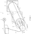
- FIGS. 1 , 2 , 3 , and 4 show a configuration of a linear motor according to the first embodiment of the invention. The whole configuration is denoted at 1.
- the linear motor 1 comprises: a columnar stator 5 which is attached by an unillustrated predetermined method to a fixing member 3 fixed to a ground side; a cylindrical needle 7 which is positioned in a side opposite to the fixing member 3 and is movable in an axial direction of the stator 5; and a driving device 9 which supplies the needle 7 with an electric power from an external power supply 8.
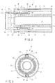
- the stator 5 comprises: an outer permanent magnet row 11 as a first permanent magnet row which is configured by arranging pairs of arcuate permanent magnets to be adjacent to each other in a manner that magnetic poles of each of the pairs of the arcuate permanent magnets are rotated by 90 degrees in a cross-section including center axes of the magnets; an outer pipe 13 as a first annular fixing member, to an inner surface of which the first permanent magnet row is fixed by a predetermined method; an inner permanent magnet row 15 as a second permanent magnet row which has magnetization vectors having radial directional components directed in the same directions as the outer permanent magnet row 11, and having axial directional components directed in the opposite directions to those of the outer permanent magnet row 11; an inner pipe 17 as a second annular fixing member, to which the inner permanent magnet row 15 is fixed by a predetermined method; a fixing disc 19 which fixes the outer pipe 13 and inner pipe 17 in a side of the fixing member 3 by an unillustrated predetermined method; and a fixing plate 23 which is notched so as not to interfere
- support plates 25 are fixed by a predetermined method, as positioning members to prevent the outer permanent magnet row 11 from moving in inner circumferential directions.
- the support plates 25 may be fixed to the outer pipe 13 and to the outer permanent magnet row 11.
- the first and second permanent magnet rows have substantially equal magnetization energies. Therefore, a very large number of magnetic fluxes directed in radial directions are distributed in a gap between the outer permanent magnet row 11 and the inner permanent magnet row 15.
- the needle 7 comprises: a winding ring 33 having a U-shaped cross-section about which a three-phase coil 31 is wound; linear bushes 35 which are attached to upper and lower four corners of the winding ring 33, and guide the winding ring 33 along the guide rods 21; an output ring 37 which is fixed to the winding ring 33 by an unillustrated method and comprises notched parts; and a notch fixing plate 39 which fixes the notched parts of the output ring 37 by an unillustrated method. Further, a lead path 43 for leading a lead line 41 as an electric-power transmission means for leading a three-phase alternating power to the three-phase coil 31 is provided in the output ring 37 and the notch fixing plate 39.
- the winding ring 33 and the linear bushes 35 function as a coil support means. Since the three-phase coil 31 is positioned in a gap where a very large number of magnetic fluxes in radial directions exist, most of the magnetic fluxes are linked at right angles with the three-phase coil 31. Therefore, a greater thrust is generated by a smaller current.
- the lead line 41 is connected to the driving device 9 as a coil excitation means.
- the driving device 9 comprises a power converter 53 and a source power converter 55 which transfer and receive an electric power through a bus line 51.
- a smoothing capacitor 57 as a power storage means and an electric storage device 59 also as a power storage means are connected to the bus line 51. Therefore, voltage fluctuation of the bus line 51 is reduced to be small even when the three-phase coil 31 consumes an electric power and when an electric power is recovered from the three-phase coil 31.
- the electric storage device 59 comprises a battery 61, a resistor 63, and a diode 65. When an electric power is supplied from the battery 61, the resistor 63 does not consume the electric power. When the battery 61 is electrically charged, the charged power is partially consumed by the resistor 63. In this manner, excessive charging of the battery 61 is restricted.
- one smoothing capacitor 57 and one electric storage device 59 are shown, a plurality of smoothing capacitors 57 as well as electric storage devices 59 may be provided at appropriated positions on the bus line 51.
- the power converter 53 comprises a PWM inverter 67 and a thrust controller 69.
- the thrust controller 69 controls a firing angle for an unillustrated power converter element group in the PWM inverter 67 so that a thrust equal to a thrust instruction value input to the thrust controller 69 from outside of the driving device 9 is generated at the three-phase coil 31.
- the supply power converter 55 comprises an inverter 71 and a regenerative-power reception controller 73. Based on an external regenerative-power-reception instruction signal, the regenerative-power reception controller 73 regenerates an electric power stored in the smoothing capacitor 57 and battery 61 to the power supply 8, and controls a firing angle of the inverter 71 to store an electric power from the power supply 8.
- the thrust controller 69 comprises: current sensors 75 which detect at least excitation currents at phases U and W among phases U, V, and W of the three-phase coil 31; and a position sensor 77 which detects a relative position of the three-phase coil 31 relative to the outer permanent magnet row 11. Torque control is performed based on signals from these sensors.
- the position sensor 77 comprises: a scale 79 which is attached to an upper part of an inner surface of the outer pipe 13 of the stator 5; and an optical pickup 81 which detects a gauge of the scale 79. Needless to say, detected position information is introduced into the driving device 9 through an unillustrated position-sensor output line bundled in the lead line 41. The position information from the position sensor 77 is converted into moving distance information of the needle 5 by the thrust controller 69, and is output to outside of the driving device 9. In this manner, an external control device is allowed to perform speed control and positioning control of the needle 5.
- the needle 7 stops without outputting any thrust. If a thrust instruction value is then introduced into the driving device 9 from an external control device, for example, to move the needle 7 to a predetermined position, the current sensors 75 for the phases U and W detect excitation currents of the three-phase coil 31. Further, the position sensor 77 detects a relative position of the three-phase coil 31 in relation to the outer and inner permanent magnet rows 11 and 15. The thrust controller 69 excites the three-phase coil 31 by an excitation current at which a thrust equal to the thrust instruction value is to be generated. Then, the needle 7 starts moving toward the predetermined position by the thrust generated by the three-phase coil 31. The needle 7 continues moving in accordance with predetermined control, such as speed control and positioning control.
- predetermined control such as speed control and positioning control.
- the needle 7 reaches the predetermined position, and operation of the linear motor 1 then ends.
- the external thrust instruction value then becomes zero, which is introduced to the thrust controller 69.
- the excitation current to the three-phase coil 31 then becomes zero, and the device stops again.
- a self inductance of the three-phase coil 31 is small since neither an iron core nor a yoke exists within main magnetic fluxes created by the inner and outer permanent magnet rows 11 and 15 or near the three-phase coil 31. Therefore, even if the needle 7 moves at a high speed, a voltage required for electrically conducting a predetermined excitation current to the three-phase coil 31 is reduced, and a requested voltage for the power supply 8 is reduced. Further, since the needle 7 requires neither an iron core nor a yoke, weight reduction is achieved, and a large part of the three-phase coil 31 is linked with the main magnetic fluxes created by the outer and inner permanent magnet rows 11 and 15. Therefore, the thrust/weight ratio improves. Accordingly, the controllability improves in making the needle 7 respond at a high speed, and contributes to energy saving.
- the permanent magnet rows are configured as stators.
- this configuration does not limit use of the permanent magnet rows as stators.
- a coil support means is configured to be fixed to the ground side and if permanent magnet rows are configured as needles.
- the lead line 41 is not applied with any force, and risks of disconnections and damages are avoidable. Therefore, reliability improves advantageously.
- a linear motor according to the present embodiment is denoted, as a whole, at 1'.
- the linear motor 1' comprises: a stator 5 which is fixed to a ground side by an unillustrated means which uses an outer permanent magnet row 11' and an inner permanent magnet row 15' as stator field magnets; a needle 7 which uses a three-phase coil 31 as an armature; and a driving device 9.
- the stator 5 comprises: an outer permanent magnet row 11', as a first permanent magnet row, which is configured by arranging ring permanent magnets to be adjacent to each other in a manner that magnetic poles of the ring permanent magnets are rotated by 90 degrees in a cross-section including center axes of the magnets; an outer pipe 13; an inner permanent magnet row 15; an inner pipe 17; and fixing plates 23 which are notched so as not to interfere with the needle 7 and fix the outer pipe 13 and the inner pipe 17 by an unillustrated predetermined method.
- the first and second permanent magnet rows have substantially equal magnetization energies. Therefore, a very large number of magnetic fluxes are distributed in a gap between the outer permanent magnet row 11' and the inner permanent magnet row 15.
- guide rods 21' are attached to outer upper and lower parts of the outer pipe 13 through guide-rod support members 111 and 113.
- electrodes 103, 105, 107, and 109 each divided into two upper and lower halves are fixed to surfaces of the guide rods 21'.
- Lead lines 41 from the respective electrodes are bundled by a predetermined method, and are introduced into the driving device 9 through lead paths 43 provided in the guide-rod support members 111.
- An optical pickup 81 for detecting a gauge of a scale 79 which the needle 7 comprises is attached at a predetermined position to one of the fixing plates 23.
- the needle 7 comprises: a winding ring 33; an output ring 37 which is fixed to two ends of the winding ring 33 by an unillustrated method and comprises notched parts; a notch fixing plate 39 which fixes the notched parts of the output ring 37 by an unillustrated method; and linear bushes 35' and 35" which are attached to ends of the output ring 37, and guide the winding ring 33 along the guide rods 21'.
- the linear bushes 35' each comprise a slidable electrode 101 which makes contact with the electrodes 103, 105, 107, and 109 provided on a surface of a guide rod 21'.
- the lead lines 41 connected at one ends to a three-phase coil 31 are connected to the slidable electrodes 101 through the lead paths 43 provided in the output ring 37 and the linear bushes 35'.
- the three-phase coil 31 is electrically connected to the driving device 9 through the electrodes 103, 105, 107, and 109 in the side of the stator 5.
- currents having phases U, V, and W corresponding to three-phase alternating-current voltages generated by the driving device 9 and a neutral current are made to flow respectively through the electrodes 103, 105, 107, and 109, and the three-phase coil 31 is excited, to move the needle 7 at a predetermined thrust.
- the winding ring 33 and linear bushes 35' and 35" function as a coil support means.
- the lead lines 41, slidable electrodes 101, and electrodes 103, 105, 107, and 109 function as an electric-power transmission means.
- a scale and an optical pickup are used for a position sensor for obtaining position information of a needle in relation to a stator.
- This use does not limit a means for obtaining position information.
- a magnetic position sensor or a sensorless method of estimating a position from a counter electromotive force of a three-phase coil 31 may be Used.
- each, either permanent magnet rows or a coil support means is configured as a stator.
- This configuration does not limit use of either permanent magnet rows or a coil support means as a stator.
- Both the coil support means and permanent magnet row may be configured to be movable and to move relatively to each other.
- the invention can be variously modified without departing from the scope of the invention as defined by the claims.
- the invention is not limited just to the foregoing embodiments but can be embodied with constitutive elements modified in a practical phase without departing from the scope of the invention.
- Further various embodiments may be derived by appropriately combining a plurality of constitutive elements disclosed in the foregoing embodiments. For example, several constitutive elements may be omitted from the whole constitutive elements disclosed in the foregoing embodiments. Such constitutive elements may be appropriately combined between different embodiments.
- PWM inverter 69... Thrust controller, 71... Inverter, 73... Regenerative-power reception controller, 75... Current sensor, 77... Position sensor, 79... Scale, 81... Optical pickup, 101... Slidable electrode, 103, 105, 107, 109... Electrode
Description
- The present invention relates to a linear motor which is capable of making a high speed response and obtains a greater thrust with a lighter weight.
- Since a motor which employs a Halbach array can link a large number of magnetic fluxes with a coil without using an iron core, studies to put the motor to practical use are making rapid progress.
- To substitute a Halbach array for a conventional field magnet which is configured by an iron core and permanent magnets for the purpose of increasing torque is widely employed as a usage of the Halbach array, as disclosed in
Patent Document 1 and Patent Document 2. According toPatent Document 3, an inertia moment of a rotary part of a motor wheel is reduced by configuring a wheel-in motor with use of magnets having a smaller density than iron in a side of an outer rotor. In each of these publications, a magnetic path is formed by using an iron core in a side of an armature, and is thus configured to reduce magnetic resistance of a magnetic circuit formed by a field magnet. - Halbach arrays have been employed not only in rotary motors as described above but also in linear motors. Patent Document 4 discloses a linear motor in which field magnets constructed in a Halbach array on yokes are opposed to each other over a gap, to arrange an armature coil wire in a plane in the gap.
- When the armature coil wire is thus arranged in a plane, an armature current directed in a traveling direction of the linear motor or a direction opposite to the travelling direction is linked with magnetic fluxes of field magnets, at coil ends. Therefore, no thrust is generated at a part of the armature coil. Besides, an electromagnetic force acts in a direction perpendicular to the travelling direction, so that a high thrust cannot be obtained. A further problem occurs in that lifetime of the armature coil shortens.
- On the other side,
Patent Document 5 discloses a linear motor using a Halbach array which employs no iron core. However, in this linear motor, field magnets are formed by columnar permanent magnet rows, and an armature coil is arranged so as to be wound about one of the field magnets of the permanent magnet rows which are opposed to each other over a gap. Therefore, a part of the armature coil is not linked with magnetic fluxes generated by the field magnets, and a generated thrust therefore lowers as a problem. - As described above, in conventional motors and linear motors, a weight/torque ratio or weight/thrust ratio is not satisfactorily small. When such an actuator operates, a power which matches an excessive mass is required, and operating costs increase. Consequently, a problem occurs in increase of emission of carbon dioxide. A further problem occurs in controllability of an iron core when an iron core is used.
-
- Patent Document 1: Jpn. Pat. Appln. KOKAI Publication No.
2004-350427 - Patent Document 2: Jpn. Pat. Appln. KOKAI Publication No.
2006-262603 - Patent Document 3: Jpn. Pat. Appln. KOKAI Publication No.
2006-187116 - Patent Document 4: Jpn. Pat. Appln. KOKAI Publication No.
2007-19127 - Patent Document 5: Jpn. Pat. Appln. KOKAI Publication No.
2007-82352 - In addition to that,
CN-A-101 127 474 discloses a linear motor according to the preamble ofclaim 1. - Thus, conventional linear motors have a problem that use of an iron core causes a greater weight/thrust ratio and involves greater consumption of electric power. To solve this problem, a coil armature is provided around field magnets. However, magnetic fluxes of the field magnets are not all linked with a coil but the weight/thrust ratio increases consequently.
- The present invention has been made based on such situations and has an object of providing a linear motor which lowers a weight/thrust ratio, suppresses power consumption, and reduces operation costs.
- A linear motor of the present invention comprises the features of
claim 1. - According to the configuration as described above, strong magnetic fluxes can be linked with an armature coil without using an iron core, and the whole armature coil is linked with magnetic fluxes of field magnets.
- Advantageous Effects of Invention According to the linear motor of the invention, a strong magnetic field is linked with a whole armature coil, and a weight/thrust ratio can be therefore reduced. Accordingly, power consumption during operation can be suppressed, and operating costs can be reduced.
-
-
FIG. 1 is a schematic view of an entire structure of the first embodiment of the invention; -
FIG. 2 is a cross-sectional view of the embodiment taken along A-A'; -
FIG. 3 is a cross-sectional view of the embodiment taken along C-C'; -
FIG. 4 is a cross-sectional view of the embodiment taken along B-B' ; -
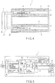
FIG. 5 is a block diagram showing a configuration of a driving device in the embodiment; -
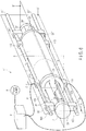
FIG. 6 is a schematic view of an entire structure of the second embodiment of the invention; -
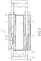
FIG. 7 is a cross-sectional view of the embodiment taken along A-A' ; -
FIG. 8 is a cross-sectional view of the embodiment taken along C-C'; and -
FIG. 9 is a cross-sectional view of the embodiment taken along B-B'. - Hereinafter, embodiments of the invention will be described in details with reference to the drawings.
-
FIGS. 1 ,2 ,3 , and4 show a configuration of a linear motor according to the first embodiment of the invention. The whole configuration is denoted at 1. - The
linear motor 1 comprises: acolumnar stator 5 which is attached by an unillustrated predetermined method to a fixingmember 3 fixed to a ground side; acylindrical needle 7 which is positioned in a side opposite to the fixingmember 3 and is movable in an axial direction of thestator 5; and adriving device 9 which supplies theneedle 7 with an electric power from anexternal power supply 8. - The
stator 5 comprises: an outerpermanent magnet row 11 as a first permanent magnet row which is configured by arranging pairs of arcuate permanent magnets to be adjacent to each other in a manner that magnetic poles of each of the pairs of the arcuate permanent magnets are rotated by 90 degrees in a cross-section including center axes of the magnets; anouter pipe 13 as a first annular fixing member, to an inner surface of which the first permanent magnet row is fixed by a predetermined method; an innerpermanent magnet row 15 as a second permanent magnet row which has magnetization vectors having radial directional components directed in the same directions as the outerpermanent magnet row 11, and having axial directional components directed in the opposite directions to those of the outerpermanent magnet row 11; aninner pipe 17 as a second annular fixing member, to which the innerpermanent magnet row 15 is fixed by a predetermined method; afixing disc 19 which fixes theouter pipe 13 andinner pipe 17 in a side of the fixingmember 3 by an unillustrated predetermined method; and a fixingplate 23 which is notched so as not to interfere with theneedle 7, and fixes, in combination with the fixingdisc 19, theouter pipe 13 andinner pipe 17 and twoguide rods 21 by an unillustrated predetermined method. To inner upper and lower parts of theouter pipe 13,support plates 25 are fixed by a predetermined method, as positioning members to prevent the outerpermanent magnet row 11 from moving in inner circumferential directions. Thesupport plates 25 may be fixed to theouter pipe 13 and to the outerpermanent magnet row 11. Further, the first and second permanent magnet rows have substantially equal magnetization energies. Therefore, a very large number of magnetic fluxes directed in radial directions are distributed in a gap between the outerpermanent magnet row 11 and the innerpermanent magnet row 15. - The
needle 7 comprises: a windingring 33 having a U-shaped cross-section about which a three-phase coil 31 is wound;linear bushes 35 which are attached to upper and lower four corners of the windingring 33, and guide the windingring 33 along theguide rods 21; anoutput ring 37 which is fixed to the windingring 33 by an unillustrated method and comprises notched parts; and anotch fixing plate 39 which fixes the notched parts of theoutput ring 37 by an unillustrated method. Further, alead path 43 for leading alead line 41 as an electric-power transmission means for leading a three-phase alternating power to the three-phase coil 31 is provided in theoutput ring 37 and thenotch fixing plate 39. Needless to say, the windingring 33 and thelinear bushes 35 function as a coil support means. Since the three-phase coil 31 is positioned in a gap where a very large number of magnetic fluxes in radial directions exist, most of the magnetic fluxes are linked at right angles with the three-phase coil 31. Therefore, a greater thrust is generated by a smaller current. - The
lead line 41 is connected to thedriving device 9 as a coil excitation means. The drivingdevice 9 comprises apower converter 53 and asource power converter 55 which transfer and receive an electric power through abus line 51. - As shown in
FIG. 5 , a smoothingcapacitor 57 as a power storage means and anelectric storage device 59 also as a power storage means are connected to thebus line 51. Therefore, voltage fluctuation of thebus line 51 is reduced to be small even when the three-phase coil 31 consumes an electric power and when an electric power is recovered from the three-phase coil 31. Theelectric storage device 59 comprises abattery 61, aresistor 63, and adiode 65. When an electric power is supplied from thebattery 61, theresistor 63 does not consume the electric power. When thebattery 61 is electrically charged, the charged power is partially consumed by theresistor 63. In this manner, excessive charging of thebattery 61 is restricted. Although one smoothingcapacitor 57 and oneelectric storage device 59 are shown, a plurality of smoothingcapacitors 57 as well aselectric storage devices 59 may be provided at appropriated positions on thebus line 51. - The
power converter 53 comprises aPWM inverter 67 and athrust controller 69. Thethrust controller 69 controls a firing angle for an unillustrated power converter element group in thePWM inverter 67 so that a thrust equal to a thrust instruction value input to thethrust controller 69 from outside of thedriving device 9 is generated at the three-phase coil 31. - The
supply power converter 55 comprises aninverter 71 and a regenerative-power reception controller 73. Based on an external regenerative-power-reception instruction signal, the regenerative-power reception controller 73 regenerates an electric power stored in the smoothingcapacitor 57 andbattery 61 to thepower supply 8, and controls a firing angle of theinverter 71 to store an electric power from thepower supply 8. - The
thrust controller 69 comprises:current sensors 75 which detect at least excitation currents at phases U and W among phases U, V, and W of the three-phase coil 31; and aposition sensor 77 which detects a relative position of the three-phase coil 31 relative to the outerpermanent magnet row 11. Torque control is performed based on signals from these sensors. Theposition sensor 77 comprises: ascale 79 which is attached to an upper part of an inner surface of theouter pipe 13 of thestator 5; and anoptical pickup 81 which detects a gauge of thescale 79. Needless to say, detected position information is introduced into thedriving device 9 through an unillustrated position-sensor output line bundled in thelead line 41. The position information from theposition sensor 77 is converted into moving distance information of theneedle 5 by thethrust controller 69, and is output to outside of thedriving device 9. In this manner, an external control device is allowed to perform speed control and positioning control of theneedle 5. - Next, a description will be made of operation of the linear motor according to the embodiment configured as described above.
- When the device stops, the
needle 7 stops without outputting any thrust. If a thrust instruction value is then introduced into thedriving device 9 from an external control device, for example, to move theneedle 7 to a predetermined position, thecurrent sensors 75 for the phases U and W detect excitation currents of the three-phase coil 31. Further, theposition sensor 77 detects a relative position of the three-phase coil 31 in relation to the outer and innerpermanent magnet rows thrust controller 69 excites the three-phase coil 31 by an excitation current at which a thrust equal to the thrust instruction value is to be generated. Then, theneedle 7 starts moving toward the predetermined position by the thrust generated by the three-phase coil 31. Theneedle 7 continues moving in accordance with predetermined control, such as speed control and positioning control. Theneedle 7 reaches the predetermined position, and operation of thelinear motor 1 then ends. When the operation ends, the external thrust instruction value then becomes zero, which is introduced to thethrust controller 69. The excitation current to the three-phase coil 31 then becomes zero, and the device stops again. - When the device operates, a self inductance of the three-
phase coil 31 is small since neither an iron core nor a yoke exists within main magnetic fluxes created by the inner and outerpermanent magnet rows phase coil 31. Therefore, even if theneedle 7 moves at a high speed, a voltage required for electrically conducting a predetermined excitation current to the three-phase coil 31 is reduced, and a requested voltage for thepower supply 8 is reduced. Further, since theneedle 7 requires neither an iron core nor a yoke, weight reduction is achieved, and a large part of the three-phase coil 31 is linked with the main magnetic fluxes created by the outer and innerpermanent magnet rows needle 7 respond at a high speed, and contributes to energy saving. - In the first embodiment of the present invention as described above, the permanent magnet rows are configured as stators. However, this configuration does not limit use of the permanent magnet rows as stators. There is no problem if a coil support means is configured to be fixed to the ground side and if permanent magnet rows are configured as needles. When the coil support means is used as a stator, the
lead line 41 is not applied with any force, and risks of disconnections and damages are avoidable. Therefore, reliability improves advantageously. - Next, the second embodiment of the invention will be described based on
FIGS. 6 ,7 ,8 , and9 . To simplify descriptions, common parts are respectively denoted at common reference signs, and descriptions thereof will be omitted. - In
FIGS. 6 ,7 ,8 , and9 , a linear motor according to the present embodiment is denoted, as a whole, at 1'. The linear motor 1' comprises: astator 5 which is fixed to a ground side by an unillustrated means which uses an outer permanent magnet row 11' and an inner permanent magnet row 15' as stator field magnets; aneedle 7 which uses a three-phase coil 31 as an armature; and adriving device 9. - The
stator 5 comprises: an outer permanent magnet row 11', as a first permanent magnet row, which is configured by arranging ring permanent magnets to be adjacent to each other in a manner that magnetic poles of the ring permanent magnets are rotated by 90 degrees in a cross-section including center axes of the magnets; anouter pipe 13; an innerpermanent magnet row 15; aninner pipe 17; and fixingplates 23 which are notched so as not to interfere with theneedle 7 and fix theouter pipe 13 and theinner pipe 17 by an unillustrated predetermined method. Further, the first and second permanent magnet rows have substantially equal magnetization energies. Therefore, a very large number of magnetic fluxes are distributed in a gap between the outer permanent magnet row 11' and the innerpermanent magnet row 15. - Further, in the
stator 5 according to the present embodiment, guide rods 21' are attached to outer upper and lower parts of theouter pipe 13 through guide-rod support members rod support members 111 from ends of the guide rods 21' in a side of the guide-rod support members 111,electrodes Lead lines 41 from the respective electrodes are bundled by a predetermined method, and are introduced into thedriving device 9 throughlead paths 43 provided in the guide-rod support members 111. Anoptical pickup 81 for detecting a gauge of ascale 79 which theneedle 7 comprises is attached at a predetermined position to one of the fixingplates 23. - The
needle 7 comprises: a windingring 33; anoutput ring 37 which is fixed to two ends of the windingring 33 by an unillustrated method and comprises notched parts; anotch fixing plate 39 which fixes the notched parts of theoutput ring 37 by an unillustrated method; andlinear bushes 35' and 35" which are attached to ends of theoutput ring 37, and guide the windingring 33 along the guide rods 21'. The linear bushes 35' each comprise aslidable electrode 101 which makes contact with theelectrodes phase coil 31 are connected to theslidable electrodes 101 through thelead paths 43 provided in theoutput ring 37 and the linear bushes 35'. In this manner, the three-phase coil 31 is electrically connected to thedriving device 9 through theelectrodes stator 5. Needless to say, currents having phases U, V, and W corresponding to three-phase alternating-current voltages generated by the drivingdevice 9 and a neutral current are made to flow respectively through theelectrodes phase coil 31 is excited, to move theneedle 7 at a predetermined thrust. - In the present embodiment, the winding
ring 33 andlinear bushes 35' and 35" function as a coil support means. The lead lines 41,slidable electrodes 101, andelectrodes - In the linear motor 1' configured as described above, magnetic fields generated by the outer permanent magnet row 11' and the inner
permanent magnet row 15 are linked with the three-phase coil 31 over the whole circumference thereof. Therefore, an electric power supplied from the drivingdevice 9 can be efficiently converted into a thrust. In addition, when theneedle 7 moves, theslidable electrodes 101 move in contact with theelectrodes needle 7 is rapidly accelerated or decelerated, the lead lines 41 are not damaged. Accordingly, reliability and durability of the motor improve advantageously. - In the foregoing embodiments each, a scale and an optical pickup are used for a position sensor for obtaining position information of a needle in relation to a stator. This use does not limit a means for obtaining position information. For example, a magnetic position sensor or a sensorless method of estimating a position from a counter electromotive force of a three-
phase coil 31 may be
Used. - Also in the foregoing embodiments each, either permanent magnet rows or a coil support means is configured as a stator. This configuration does not limit use of either permanent magnet rows or a coil support means as a stator. Both the coil support means and permanent magnet row may be configured to be movable and to move relatively to each other.
- Furthermore, the invention can be variously modified without departing from the scope of the invention as defined by the claims. In brief, the invention is not limited just to the foregoing embodiments but can be embodied with constitutive elements modified in a practical phase without departing from the scope of the invention. Further various embodiments may be derived by appropriately combining a plurality of constitutive elements disclosed in the foregoing embodiments. For example, several constitutive elements may be omitted from the whole constitutive elements disclosed in the foregoing embodiments. Such constitutive elements may be appropriately combined between different embodiments.
- 1, 1"... Linear motor, 3... Fixing member, 5... Stator, 7... Needle, 8... Power supply, 9... Driving device, 11, 11'... Outer permanent magnet row, 13... Outer pipe, 15... Inner permanent magnet row, 17... Inner pipe, 19... Fixing disc, 21, 21'... Guide rod, 23... Fixing plate, 25... Support plate, 31... Three-phase coil, 33... Winding ring, 35, 35', 35"... Linear bush, 37... Output ring, 39, 39'... Notch fixing plate, 41... Lead line, 43... Lead path, 51... Bus line, 53... Power converter, 55...
Source power converter
Claims (7)
- A linear motor comprising:a first permanent magnet row (11) configured by arranging pairs of annular or arcuate permanent magnets to be adjacent to each other in a manner that magnetic poles of each of the pairs of the permanent magnets are rotated by at most 90 degrees to each other of the permanent magnets in a cross-section including center axes of the permanent magnets;a second permanent magnet row (15) of annular or arcuate permanent magnets having magnetization vectors whose radial directional components are directed in the same directions as radial directional components of magnetization vectors of the corresponding radially adjacent magnets of the first permanent magnet row (11), and whose axial directional components are directed in directions opposite to axial directional components of magnetization vectors of the corresponding radially adjacent magnets of the first permanent magnet row (11);a three-phase coil (31) provided between the first permanent magnet row (11) and the second permanent magnet row (15), and formed of conductors provided outside the second permanent magnet row (15);a coil support means (33, 35) to which the three-phase coil (31) is fixed, and which move the three-phase coil (31) in parallel with a center axis of the second permanent magnet row (15);a magnet fixing means (13, 17) which fixes the first permanent magnet row (11) and the second permanent magnet row (15) to be opposed to each other in a manner that the radial directional components of the magnetization vectors of each of the rows are directed in the same directions;a coil excitation means (9) which excites the three-phase coil (31) and generates a predetermined thrust between the coil support means (33, 35) and the magnet fixing means (13, 17); andan electric-power transmission means (41) which transmits an electric power output from the coil excitation means (9) to the three-phase coil (31),characterized in thatthe first (11) and second permanent magnet rows (15) have substantially equal magnetization energies, andneither an iron core nor a yoke exists within main magnetic fluxes created by the first and second permanent magnet rows (11, 15) or near the three-phase coil (31).
- The linear motor of Claim 1, wherein the magnet fixing means (13, 17) comprises a fixing member (3) to which a stator (5) of the linear motor is attached and which is itself fixed to a ground side.
- The linear motor of Claim 1, wherein the electric-power transmission means (41) comprises a slidable part.
- The linear motor of Claim 1, wherein the first permanent magnet row (11) comprises a first annular fixing member (13) which fixes the first permanent magnet row (11) from outside.
- The linear motor of Claim 1, wherein the second permanent magnet row (15) comprises a second annular fixing member (17) which fixes the second permanent magnet row (15) from inside.
- The linear motor of Claim 4, wherein the first annular fixing member (13) comprises a positioning member (25) which positions the first permanent magnet row (11) inside the first annular fixing member (13).
- The linear motor of Claim 4, wherein the coil support means (33, 35) is comprised outside the first annular fixing member (13).
Applications Claiming Priority (2)
| Application Number | Priority Date | Filing Date | Title |
|---|---|---|---|
| JP2008331349A JP5404029B2 (en) | 2008-12-25 | 2008-12-25 | Linear motor |
| PCT/JP2009/071378 WO2010074112A1 (en) | 2008-12-25 | 2009-12-24 | Linear motor |
Publications (3)
| Publication Number | Publication Date |
|---|---|
| EP2372886A1 EP2372886A1 (en) | 2011-10-05 |
| EP2372886A4 EP2372886A4 (en) | 2017-08-09 |
| EP2372886B1 true EP2372886B1 (en) | 2019-10-02 |
Family
ID=42287719
Family Applications (1)
| Application Number | Title | Priority Date | Filing Date |
|---|---|---|---|
| EP09834910.3A Active EP2372886B1 (en) | 2008-12-25 | 2009-12-24 | Linear motor |
Country Status (5)
| Country | Link |
|---|---|
| EP (1) | EP2372886B1 (en) |
| JP (1) | JP5404029B2 (en) |
| CN (1) | CN102265490B (en) |
| BR (1) | BRPI0923573A2 (en) |
| WO (1) | WO2010074112A1 (en) |
Families Citing this family (27)
| Publication number | Priority date | Publication date | Assignee | Title |
|---|---|---|---|---|
| JP5596613B2 (en) * | 2011-04-18 | 2014-09-24 | 株式会社ソディック | Linear motor |
| JP5370697B2 (en) * | 2011-05-13 | 2013-12-18 | 株式会社安川電機 | Linear motor |
| JP2013215021A (en) * | 2012-03-30 | 2013-10-17 | Kogakuin Univ | Electromagnetic induction device |
| JP2013229247A (en) * | 2012-04-26 | 2013-11-07 | Toshiba Corp | Switchgear for electric power and operation mechanism thereof |
| JP6189028B2 (en) | 2012-10-22 | 2017-08-30 | 株式会社東芝 | Power switchgear and its operating mechanism |
| DE102012025323A1 (en) * | 2012-12-22 | 2014-06-26 | Festo Ag & Co. Kg | Method for operating a linear motor arrangement and linear motor arrangement |
| JP2015043656A (en) * | 2013-08-26 | 2015-03-05 | 株式会社東芝 | Circuit breaker |
| CN103618430B (en) * | 2013-12-12 | 2015-12-16 | 中国船舶重工集团公司第七0四研究所 | The linear electric motors of drum type brake and flat mixed structure |
| CN103647431B (en) * | 2013-12-16 | 2015-12-02 | 江苏大学 | The each extremely free-standing permanent-magnet linear fault-tolerant motor of second modular |
| JP2017511681A (en) * | 2014-04-16 | 2017-04-20 | ヌクレウス サイエンティフィック, インク.Nucleus Scientific, Inc. | Magnetic position coupling and valve mechanism |
| WO2015191047A1 (en) | 2014-06-10 | 2015-12-17 | The Regents Of The University Of Michigan | Mechanical amplifier for energy harvester |
| WO2015191045A1 (en) * | 2014-06-10 | 2015-12-17 | The Regents Of The University Of Michigan | Electromagnetic energy transducer |
| CN105449976B (en) * | 2014-08-28 | 2018-06-01 | 上海微电子装备(集团)股份有限公司 | The driving device and control method of a kind of permanent-magnetism linear motor |
| CN104319976B (en) * | 2014-11-18 | 2017-01-18 | 南京航空航天大学 | Internal armature field enhancement-type permanent magnet flux-switching linear motor |
| CN105811730B (en) * | 2014-12-30 | 2018-06-29 | 上海微电子装备(集团)股份有限公司 | A kind of six degree of freedom linear motor |
| CN104578681B (en) * | 2015-01-21 | 2017-03-22 | 朱福善 | Composition of trigger type brushless direct-current linear motor and drive method |
| JP5870326B1 (en) | 2015-01-22 | 2016-02-24 | サンテスト株式会社 | Voice coil motor and direct acting servo valve using the voice coil motor |
| KR20160091057A (en) | 2015-01-23 | 2016-08-02 | 에이텍 코퍼레이션 | Electromagnetic induction apparatus |
| CN104953784A (en) * | 2015-06-25 | 2015-09-30 | 金陵科技学院 | Double-rotor type low-speed cylindrical permanent magnet linear generator |
| JP6586027B2 (en) * | 2016-02-16 | 2019-10-02 | 株式会社日立製作所 | Linear motor and shut-off device |
| US20180062491A1 (en) * | 2016-08-25 | 2018-03-01 | United States Department Of The Navy | Interstructural and Inertial Actuator |
| CN112713739B (en) | 2016-09-13 | 2024-02-27 | 核科学股份有限公司 | Multi-link electric drive system |
| JP2018113749A (en) * | 2017-01-10 | 2018-07-19 | 橘コンサルタンツ株式会社 | Energy Converter |
| US11239715B2 (en) | 2017-08-30 | 2022-02-01 | Kogakuin University | Electromagnetic device |
| US11128244B2 (en) | 2017-10-25 | 2021-09-21 | Mitsuba Corporation | Device for detecting rotation direction and method for detecting rotation direction of motor, and motor control device |
| RU191798U1 (en) * | 2019-04-15 | 2019-08-22 | Валерий Петрович Бордыков | LINEAR ELECTRIC MOTOR |
| CN112242785B (en) * | 2019-07-17 | 2022-06-14 | 华为技术有限公司 | Linear motor, lens assembly and electronic equipment |
Family Cites Families (12)
| Publication number | Priority date | Publication date | Assignee | Title |
|---|---|---|---|---|
| JPS6292757A (en) * | 1985-10-16 | 1987-04-28 | Sumitomo Special Metals Co Ltd | Voice coil motor |
| JP3945916B2 (en) * | 1998-09-04 | 2007-07-18 | 三洋電機株式会社 | Movable iron core type linear motor |
| JP2001008430A (en) * | 1999-06-16 | 2001-01-12 | Nikon Corp | Motor device, stage device, and aligner |
| JP2001086725A (en) * | 1999-09-10 | 2001-03-30 | Nikon Corp | Linear motor, stage system, and aligner |
| JP3832556B2 (en) * | 2000-02-25 | 2006-10-11 | 株式会社安川電機 | Canned linear motor |
| JP2003333823A (en) * | 2002-05-13 | 2003-11-21 | Yaskawa Electric Corp | Voice coil type linear motor |
| JP2004350427A (en) | 2003-05-22 | 2004-12-09 | Denso Corp | Rotating electric machine and its rotor |
| JP4728639B2 (en) | 2004-12-27 | 2011-07-20 | 株式会社デンソー | Electric wheel |
| JP2006262603A (en) | 2005-03-16 | 2006-09-28 | Asmo Co Ltd | Rotary electric machine |
| JP2007019127A (en) | 2005-07-06 | 2007-01-25 | Yaskawa Electric Corp | Periodic magnetic field generator and linear motor using the same |
| JP2007082352A (en) | 2005-09-15 | 2007-03-29 | Institute Of Physical & Chemical Research | Linear actuator |
| CN101127474B (en) * | 2007-09-19 | 2010-07-14 | 南京理工大学 | High power density motive loop permanent magnetic linear electromotor |
-
2008
- 2008-12-25 JP JP2008331349A patent/JP5404029B2/en not_active Expired - Fee Related
-
2009
- 2009-12-24 EP EP09834910.3A patent/EP2372886B1/en active Active
- 2009-12-24 CN CN2009801518829A patent/CN102265490B/en not_active Expired - Fee Related
- 2009-12-24 BR BRPI0923573A patent/BRPI0923573A2/en not_active IP Right Cessation
- 2009-12-24 WO PCT/JP2009/071378 patent/WO2010074112A1/en active Application Filing
Non-Patent Citations (1)
| Title |
|---|
| None * |
Also Published As
| Publication number | Publication date |
|---|---|
| EP2372886A4 (en) | 2017-08-09 |
| EP2372886A1 (en) | 2011-10-05 |
| JP5404029B2 (en) | 2014-01-29 |
| CN102265490B (en) | 2013-06-26 |
| BRPI0923573A2 (en) | 2016-01-26 |
| WO2010074112A1 (en) | 2010-07-01 |
| CN102265490A (en) | 2011-11-30 |
| JP2010154688A (en) | 2010-07-08 |
Similar Documents
| Publication | Publication Date | Title |
|---|---|---|
| EP2372886B1 (en) | Linear motor | |
| US20070296298A1 (en) | Electric machine having segmented stator | |
| JP2019024296A (en) | Rotary electric machine | |
| US9461511B2 (en) | Electric machine with permanently excited armature and associated permanently excited armature | |
| CN109672276B (en) | Alternating pole permanent magnet biased bearingless doubly salient motor and control method thereof | |
| US20200303973A1 (en) | Rotating electric device | |
| CN101847918A (en) | Be used for optimized electric machine for smart actuators | |
| JP2002218729A (en) | System combined with permanent magnet excited synchronous motor and noncontact power supply | |
| JP2013215021A (en) | Electromagnetic induction device | |
| TW201136107A (en) | Linear motor | |
| JP2009201343A (en) | Permanent magnet rotating electrical machine | |
| US20110037337A1 (en) | Rotary electromagnetic machines | |
| CN102160267B (en) | Permanent magnet-type stepping motors | |
| CN111247736A (en) | System and method for preventing demagnetization of permanent magnets in an electric machine | |
| US20210313851A1 (en) | Multi-Layer Axial and Radial flux Vernier Permanent Magnet Motor | |
| Sangha et al. | Design and test results for dual-lane fault-tolerant PM motor for safety critical aircraft actuator | |
| CN112994390A (en) | Birotor radial permanent magnet motor | |
| US11462955B2 (en) | Electric rotating machine, electric rotating machine system, vehicle, power generator, lifting device, and robot | |
| RU2599056C1 (en) | High-speed multi-phase synchronous generator | |
| JP6958504B2 (en) | Rotating machine stator | |
| CN104137394A (en) | Electric motor | |
| CN110994822B (en) | Stator structure with self-adaptive magnetic field correction capability | |
| US20130009523A1 (en) | Electromechanical device, robot, and mobile unit | |
| Popa et al. | Theoretical and experimental study of a modular tubular transverse flux reluctance machine | |
| Hsiao et al. | Integrated Design and Power Loss Minimization of Reaction Wheel Motor for Satellite Attitude Control |
Legal Events
| Date | Code | Title | Description |
|---|---|---|---|
| PUAI | Public reference made under article 153(3) epc to a published international application that has entered the european phase |
Free format text: ORIGINAL CODE: 0009012 |
|
| 17P | Request for examination filed |
Effective date: 20110620 |
|
| AK | Designated contracting states |
Kind code of ref document: A1 Designated state(s): AT BE BG CH CY CZ DE DK EE ES FI FR GB GR HR HU IE IS IT LI LT LU LV MC MK MT NL NO PL PT RO SE SI SK SM TR |
|
| DAX | Request for extension of the european patent (deleted) | ||
| RIC1 | Information provided on ipc code assigned before grant |
Ipc: H02K 41/03 20060101AFI20170309BHEP Ipc: H02P 25/06 20160101ALI20170309BHEP |
|
| RA4 | Supplementary search report drawn up and despatched (corrected) |
Effective date: 20170710 |
|
| RIC1 | Information provided on ipc code assigned before grant |
Ipc: H02K 41/03 20060101AFI20170704BHEP Ipc: H02P 25/06 20160101ALI20170704BHEP |
|
| STAA | Information on the status of an ep patent application or granted ep patent |
Free format text: STATUS: EXAMINATION IS IN PROGRESS |
|
| 17Q | First examination report despatched |
Effective date: 20180503 |
|
| GRAP | Despatch of communication of intention to grant a patent |
Free format text: ORIGINAL CODE: EPIDOSNIGR1 |
|
| STAA | Information on the status of an ep patent application or granted ep patent |
Free format text: STATUS: GRANT OF PATENT IS INTENDED |
|
| INTG | Intention to grant announced |
Effective date: 20190531 |
|
| GRAS | Grant fee paid |
Free format text: ORIGINAL CODE: EPIDOSNIGR3 |
|
| GRAA | (expected) grant |
Free format text: ORIGINAL CODE: 0009210 |
|
| STAA | Information on the status of an ep patent application or granted ep patent |
Free format text: STATUS: THE PATENT HAS BEEN GRANTED |
|
| AK | Designated contracting states |
Kind code of ref document: B1 Designated state(s): AT BE BG CH CY CZ DE DK EE ES FI FR GB GR HR HU IE IS IT LI LT LU LV MC MK MT NL NO PL PT RO SE SI SK SM TR |
|
| REG | Reference to a national code |
Ref country code: GB Ref legal event code: FG4D |
|
| REG | Reference to a national code |
Ref country code: CH Ref legal event code: EP Ref country code: AT Ref legal event code: REF Ref document number: 1187305 Country of ref document: AT Kind code of ref document: T Effective date: 20191015 |
|
| REG | Reference to a national code |
Ref country code: DE Ref legal event code: R096 Ref document number: 602009060033 Country of ref document: DE |
|
| REG | Reference to a national code |
Ref country code: IE Ref legal event code: FG4D |
|
| REG | Reference to a national code |
Ref country code: SE Ref legal event code: TRGR |
|
| REG | Reference to a national code |
Ref country code: NL Ref legal event code: MP Effective date: 20191002 |
|
| REG | Reference to a national code |
Ref country code: LT Ref legal event code: MG4D |
|
| REG | Reference to a national code |
Ref country code: AT Ref legal event code: MK05 Ref document number: 1187305 Country of ref document: AT Kind code of ref document: T Effective date: 20191002 |
|
| PG25 | Lapsed in a contracting state [announced via postgrant information from national office to epo] |
Ref country code: PT Free format text: LAPSE BECAUSE OF FAILURE TO SUBMIT A TRANSLATION OF THE DESCRIPTION OR TO PAY THE FEE WITHIN THE PRESCRIBED TIME-LIMIT Effective date: 20200203 Ref country code: BG Free format text: LAPSE BECAUSE OF FAILURE TO SUBMIT A TRANSLATION OF THE DESCRIPTION OR TO PAY THE FEE WITHIN THE PRESCRIBED TIME-LIMIT Effective date: 20200102 Ref country code: FI Free format text: LAPSE BECAUSE OF FAILURE TO SUBMIT A TRANSLATION OF THE DESCRIPTION OR TO PAY THE FEE WITHIN THE PRESCRIBED TIME-LIMIT Effective date: 20191002 Ref country code: LV Free format text: LAPSE BECAUSE OF FAILURE TO SUBMIT A TRANSLATION OF THE DESCRIPTION OR TO PAY THE FEE WITHIN THE PRESCRIBED TIME-LIMIT Effective date: 20191002 Ref country code: NL Free format text: LAPSE BECAUSE OF FAILURE TO SUBMIT A TRANSLATION OF THE DESCRIPTION OR TO PAY THE FEE WITHIN THE PRESCRIBED TIME-LIMIT Effective date: 20191002 Ref country code: AT Free format text: LAPSE BECAUSE OF FAILURE TO SUBMIT A TRANSLATION OF THE DESCRIPTION OR TO PAY THE FEE WITHIN THE PRESCRIBED TIME-LIMIT Effective date: 20191002 Ref country code: ES Free format text: LAPSE BECAUSE OF FAILURE TO SUBMIT A TRANSLATION OF THE DESCRIPTION OR TO PAY THE FEE WITHIN THE PRESCRIBED TIME-LIMIT Effective date: 20191002 Ref country code: LT Free format text: LAPSE BECAUSE OF FAILURE TO SUBMIT A TRANSLATION OF THE DESCRIPTION OR TO PAY THE FEE WITHIN THE PRESCRIBED TIME-LIMIT Effective date: 20191002 Ref country code: GR Free format text: LAPSE BECAUSE OF FAILURE TO SUBMIT A TRANSLATION OF THE DESCRIPTION OR TO PAY THE FEE WITHIN THE PRESCRIBED TIME-LIMIT Effective date: 20200103 Ref country code: NO Free format text: LAPSE BECAUSE OF FAILURE TO SUBMIT A TRANSLATION OF THE DESCRIPTION OR TO PAY THE FEE WITHIN THE PRESCRIBED TIME-LIMIT Effective date: 20200102 Ref country code: PL Free format text: LAPSE BECAUSE OF FAILURE TO SUBMIT A TRANSLATION OF THE DESCRIPTION OR TO PAY THE FEE WITHIN THE PRESCRIBED TIME-LIMIT Effective date: 20191002 |
|
| PG25 | Lapsed in a contracting state [announced via postgrant information from national office to epo] |
Ref country code: HR Free format text: LAPSE BECAUSE OF FAILURE TO SUBMIT A TRANSLATION OF THE DESCRIPTION OR TO PAY THE FEE WITHIN THE PRESCRIBED TIME-LIMIT Effective date: 20191002 Ref country code: IS Free format text: LAPSE BECAUSE OF FAILURE TO SUBMIT A TRANSLATION OF THE DESCRIPTION OR TO PAY THE FEE WITHIN THE PRESCRIBED TIME-LIMIT Effective date: 20200224 Ref country code: CZ Free format text: LAPSE BECAUSE OF FAILURE TO SUBMIT A TRANSLATION OF THE DESCRIPTION OR TO PAY THE FEE WITHIN THE PRESCRIBED TIME-LIMIT Effective date: 20191002 |
|
| REG | Reference to a national code |
Ref country code: DE Ref legal event code: R097 Ref document number: 602009060033 Country of ref document: DE |
|
| PG2D | Information on lapse in contracting state deleted |
Ref country code: IS |
|
| PG25 | Lapsed in a contracting state [announced via postgrant information from national office to epo] |
Ref country code: DK Free format text: LAPSE BECAUSE OF FAILURE TO SUBMIT A TRANSLATION OF THE DESCRIPTION OR TO PAY THE FEE WITHIN THE PRESCRIBED TIME-LIMIT Effective date: 20191002 Ref country code: RO Free format text: LAPSE BECAUSE OF FAILURE TO SUBMIT A TRANSLATION OF THE DESCRIPTION OR TO PAY THE FEE WITHIN THE PRESCRIBED TIME-LIMIT Effective date: 20191002 Ref country code: EE Free format text: LAPSE BECAUSE OF FAILURE TO SUBMIT A TRANSLATION OF THE DESCRIPTION OR TO PAY THE FEE WITHIN THE PRESCRIBED TIME-LIMIT Effective date: 20191002 Ref country code: IS Free format text: LAPSE BECAUSE OF FAILURE TO SUBMIT A TRANSLATION OF THE DESCRIPTION OR TO PAY THE FEE WITHIN THE PRESCRIBED TIME-LIMIT Effective date: 20200202 |
|
| REG | Reference to a national code |
Ref country code: CH Ref legal event code: PL |
|
| PLBE | No opposition filed within time limit |
Free format text: ORIGINAL CODE: 0009261 |
|
| STAA | Information on the status of an ep patent application or granted ep patent |
Free format text: STATUS: NO OPPOSITION FILED WITHIN TIME LIMIT |
|
| REG | Reference to a national code |
Ref country code: BE Ref legal event code: MM Effective date: 20191231 |
|
| PG25 | Lapsed in a contracting state [announced via postgrant information from national office to epo] |
Ref country code: MC Free format text: LAPSE BECAUSE OF FAILURE TO SUBMIT A TRANSLATION OF THE DESCRIPTION OR TO PAY THE FEE WITHIN THE PRESCRIBED TIME-LIMIT Effective date: 20191002 Ref country code: SK Free format text: LAPSE BECAUSE OF FAILURE TO SUBMIT A TRANSLATION OF THE DESCRIPTION OR TO PAY THE FEE WITHIN THE PRESCRIBED TIME-LIMIT Effective date: 20191002 Ref country code: IT Free format text: LAPSE BECAUSE OF FAILURE TO SUBMIT A TRANSLATION OF THE DESCRIPTION OR TO PAY THE FEE WITHIN THE PRESCRIBED TIME-LIMIT Effective date: 20191002 Ref country code: SM Free format text: LAPSE BECAUSE OF FAILURE TO SUBMIT A TRANSLATION OF THE DESCRIPTION OR TO PAY THE FEE WITHIN THE PRESCRIBED TIME-LIMIT Effective date: 20191002 |
|
| 26N | No opposition filed |
Effective date: 20200703 |
|
| GBPC | Gb: european patent ceased through non-payment of renewal fee |
Effective date: 20200102 |
|
| PG25 | Lapsed in a contracting state [announced via postgrant information from national office to epo] |
Ref country code: GB Free format text: LAPSE BECAUSE OF NON-PAYMENT OF DUE FEES Effective date: 20200102 Ref country code: LU Free format text: LAPSE BECAUSE OF NON-PAYMENT OF DUE FEES Effective date: 20191224 Ref country code: IE Free format text: LAPSE BECAUSE OF NON-PAYMENT OF DUE FEES Effective date: 20191224 |
|
| PG25 | Lapsed in a contracting state [announced via postgrant information from national office to epo] |
Ref country code: LI Free format text: LAPSE BECAUSE OF NON-PAYMENT OF DUE FEES Effective date: 20191231 Ref country code: SI Free format text: LAPSE BECAUSE OF FAILURE TO SUBMIT A TRANSLATION OF THE DESCRIPTION OR TO PAY THE FEE WITHIN THE PRESCRIBED TIME-LIMIT Effective date: 20191002 Ref country code: CH Free format text: LAPSE BECAUSE OF NON-PAYMENT OF DUE FEES Effective date: 20191231 Ref country code: BE Free format text: LAPSE BECAUSE OF NON-PAYMENT OF DUE FEES Effective date: 20191231 |
|
| PG25 | Lapsed in a contracting state [announced via postgrant information from national office to epo] |
Ref country code: CY Free format text: LAPSE BECAUSE OF FAILURE TO SUBMIT A TRANSLATION OF THE DESCRIPTION OR TO PAY THE FEE WITHIN THE PRESCRIBED TIME-LIMIT Effective date: 20191002 |
|
| PG25 | Lapsed in a contracting state [announced via postgrant information from national office to epo] |
Ref country code: HU Free format text: LAPSE BECAUSE OF FAILURE TO SUBMIT A TRANSLATION OF THE DESCRIPTION OR TO PAY THE FEE WITHIN THE PRESCRIBED TIME-LIMIT; INVALID AB INITIO Effective date: 20091224 Ref country code: MT Free format text: LAPSE BECAUSE OF FAILURE TO SUBMIT A TRANSLATION OF THE DESCRIPTION OR TO PAY THE FEE WITHIN THE PRESCRIBED TIME-LIMIT Effective date: 20191002 |
|
| PG25 | Lapsed in a contracting state [announced via postgrant information from national office to epo] |
Ref country code: TR Free format text: LAPSE BECAUSE OF FAILURE TO SUBMIT A TRANSLATION OF THE DESCRIPTION OR TO PAY THE FEE WITHIN THE PRESCRIBED TIME-LIMIT Effective date: 20191002 |
|
| PG25 | Lapsed in a contracting state [announced via postgrant information from national office to epo] |
Ref country code: MK Free format text: LAPSE BECAUSE OF FAILURE TO SUBMIT A TRANSLATION OF THE DESCRIPTION OR TO PAY THE FEE WITHIN THE PRESCRIBED TIME-LIMIT Effective date: 20191002 |
|
| REG | Reference to a national code |
Ref country code: FR Ref legal event code: PLFP Year of fee payment: 14 |
|
| PGFP | Annual fee paid to national office [announced via postgrant information from national office to epo] |
Ref country code: SE Payment date: 20231110 Year of fee payment: 15 Ref country code: FR Payment date: 20231108 Year of fee payment: 15 Ref country code: DE Payment date: 20231031 Year of fee payment: 15 |