EP2372857B1 - Bestimmung des Fehlerstromanteils eines Differenzstroms - Google Patents
Bestimmung des Fehlerstromanteils eines Differenzstroms Download PDFInfo
- Publication number
- EP2372857B1 EP2372857B1 EP10158654.3A EP10158654A EP2372857B1 EP 2372857 B1 EP2372857 B1 EP 2372857B1 EP 10158654 A EP10158654 A EP 10158654A EP 2372857 B1 EP2372857 B1 EP 2372857B1
- Authority
- EP
- European Patent Office
- Prior art keywords
- current
- electrical signal
- differential current
- differential
- scaling factor
- Prior art date
- Legal status (The legal status is an assumption and is not a legal conclusion. Google has not performed a legal analysis and makes no representation as to the accuracy of the status listed.)
- Active
Links
Images
Classifications
-
- H—ELECTRICITY
- H02—GENERATION; CONVERSION OR DISTRIBUTION OF ELECTRIC POWER
- H02H—EMERGENCY PROTECTIVE CIRCUIT ARRANGEMENTS
- H02H3/00—Emergency protective circuit arrangements for automatic disconnection directly responsive to an undesired change from normal electric working condition with or without subsequent reconnection ; integrated protection
- H02H3/26—Emergency protective circuit arrangements for automatic disconnection directly responsive to an undesired change from normal electric working condition with or without subsequent reconnection ; integrated protection responsive to difference between voltages or between currents; responsive to phase angle between voltages or between currents
- H02H3/32—Emergency protective circuit arrangements for automatic disconnection directly responsive to an undesired change from normal electric working condition with or without subsequent reconnection ; integrated protection responsive to difference between voltages or between currents; responsive to phase angle between voltages or between currents involving comparison of the voltage or current values at corresponding points in different conductors of a single system, e.g. of currents in go and return conductors
- H02H3/33—Emergency protective circuit arrangements for automatic disconnection directly responsive to an undesired change from normal electric working condition with or without subsequent reconnection ; integrated protection responsive to difference between voltages or between currents; responsive to phase angle between voltages or between currents involving comparison of the voltage or current values at corresponding points in different conductors of a single system, e.g. of currents in go and return conductors using summation current transformers
- H02H3/337—Emergency protective circuit arrangements for automatic disconnection directly responsive to an undesired change from normal electric working condition with or without subsequent reconnection ; integrated protection responsive to difference between voltages or between currents; responsive to phase angle between voltages or between currents involving comparison of the voltage or current values at corresponding points in different conductors of a single system, e.g. of currents in go and return conductors using summation current transformers avoiding disconnection due to reactive fault currents
-
- H—ELECTRICITY
- H02—GENERATION; CONVERSION OR DISTRIBUTION OF ELECTRIC POWER
- H02H—EMERGENCY PROTECTIVE CIRCUIT ARRANGEMENTS
- H02H3/00—Emergency protective circuit arrangements for automatic disconnection directly responsive to an undesired change from normal electric working condition with or without subsequent reconnection ; integrated protection
- H02H3/16—Emergency protective circuit arrangements for automatic disconnection directly responsive to an undesired change from normal electric working condition with or without subsequent reconnection ; integrated protection responsive to fault current to earth, frame or mass
Definitions
- the invention relates to a method for determining the fault current component of a differential current, which is detected as a current sum on the power of an alternator lines leading, having the features of the preamble of independent claim 1 and to a corresponding device for determining the fault current component of a differential current with the features of the preamble of independent claim 13.
- the AC generator is one in which an inverter is provided which converts a DC current provided from a power source into an AC current.
- the DC power source may be a photovoltaic system which, due to its spatial extent alone, has a not insignificant leakage capacitance to ground. From this leakage capacitance and from potential shifts with respect to ground, which occur during operation of the inverter, leakage currents to earth result. These leakage currents are reflected in a differential current, which is often monitored for the rapid detection of the occurrence of fault currents. However, large leakage currents mean that the sensitivity in the detection of residual currents is reduced by monitoring the differential current. It is therefore of interest to determine the actual fault current component of the differential current.
- AC generator power supply lines any group of AC generator lines that together carry the entire AC generator current, ie, the outgoing and the outgoing currents. These may be the output lines of the alternator, but also to act on any other wires in the alternator.
- the standards VDE 0126 and VDE 0126-1-1 require that an inverter disconnect itself from the mains within a specified switch-off time depending on the effective value of a sudden differential current across its network connections.
- this differential current is composed, in addition to a resistive fault current, of an additional capacitive leakage current, which are vectorially added to the differential current.
- the specifications of the normative test set-up and test procedure for meeting the standards mentioned above show that only a sudden increase in the fault current - even if there is a large leakage current - must lead to the inverter being disconnected from the grid.
- the differential current is measured regularly with a summation current transformer whose voltage signal is a measure of the differential current between the phases and the neutral conductor of the inverter.
- the residual current must be determined from the differential current. Due to the trend to develop transformerless inverters with increasing power and larger dimensions of the photovoltaic systems, the capacities with respect to ground and thus the leakage currents occurring increase. By using certain materials for the photovoltaic systems, this trend continues to increase. For sufficiently sensitive detection of a jump in the fault current, therefore, the leakage current must first be separated from the differential current. In addition, the detection of a jump in the fault current is made increasingly difficult, that the sensitivity of the summation current transformer is greatly reduced by high leakage currents and thus also for fault currents.
- a method and a device for determining the fault current portion of a differential current with the features of the preamble of independent claim 1 and the independent claim 13 are known. From measurements of the voltages between the input lines of the inverter and earth, more specifically the AC voltage component of these voltages, the driving force of the leakage current contained in the differential current is detected. From this voltage signal and the known Ableitkapazticianen the leakage current is calculated and subtracted from the differential current to determine the fault current. For example, in a photovoltaic system as a DC power source of the alternator Ableitkapazticianen are not constant, but change, inter alia, by precipitation on the photovoltaic panels. It is therefore not possible when using a constant specification for the Ableitkapazticianen to determine the current leakage current from the voltages of the input line to earth.
- a method and a device for insulation and fault current monitoring in an electrical AC network are known in which a formed by vectorial differential current between at least two power conductors is detected and wherein the AC component of the differential current and the active power of the AC component reproducing phase angle ⁇ are determined.
- a load shutdown occurs not only when the differential current exceeds a certain threshold, but also when the product is between the amplitude of the AC component of the Difference current and the cosine of the phase angle ⁇ exceeds a certain threshold.
- the invention has for its object to provide a method and apparatus for determining the fault current component of a differential current having the features of the preamble of independent claim 1 and independent claim 13, in which the fault current component of the differential current regardless of how large a DC component and a AC component of the fault current and to what extent the relevant Ableitkapazticianen vary determined, d. H. is separated from the leakage current component of the differential current.
- the object of the invention is achieved by a method for determining the fault current portion of a differential current having the features of independent claim 1 and by a device for determining the fault current portion of a differential current having the features of independent claim 13.
- Preferred embodiments of the new method and the new device are defined in the dependent claims.
- the electric signal reflecting, due to its dependence on the voltages on the alternator to earth, the frequency distribution of the driving force for the leakage current component of the differential current and being in phase with the leakage current component of the differential current becomes the current magnitude of the leakage capacitances multiplied by a scaling factor that is updated continuously to replicate the current Ableitstromanteil.
- the tracking is done in such a way that the RMS value of the differential current after subtraction of the scaled electrical signal at the current value of the scaling factor has a minimum.
- the phrase that the electrical signal is "multiplied by a scaling factor" includes, in particular, being linearly amplified, analog or digital, with the gain factor corresponding to the scaling factor.
- the formulation also implies that the electrical signal is subtracted from the differential current several times after a basic gain in its subsequent subtraction. Then, the scaling factor is the product of the gain and the number of times of the peel.
- the formulation that the scaled electrical signal is "subtracted" or subtracted from the differential current includes any procedure in which the differential current or a value corresponding to it is in phase by the electrical signal multiplied by the scaling factor as defined above or by that signal corresponding value is reduced.
- the electrical signal which is dependent on the voltages to ground and in phase with the leakage current component of the differential current and which forms the basis for the compensation of the leakage current component of the differential current be tapped directly at the alternator. It is therefore preferably not a signal with the properties according to the invention, which is artificially generated in response to the voltages on the alternator, but arises at the alternator itself.
- electrical signal to the alternator it may be useful to create special conditions. Concretely, the electrical signal can be generated by a leakage current, which cause the voltages on the alternator by measuring capacitors to ground. The electrical signal can be the flowing leakage current itself.
- This leakage current is an image of the total Ableitstromanteils to the differential current, ie it has its phase and frequency distribution, because in a parallel circuit of capacitors such as the measuring capacitors to the remaining leakage capacitance, the alternating currents at all frequencies in phase and proportional to their capacitances on the capacitors split.
- the difference between the small capacitance of the measuring capacitors and the much larger total leakage capacitance is compensated by the scaling factor for the electrical signal, which corresponds to an electronic amplification of the capacitance of the measuring capacitors.
- the leakage current multiplied by this scaling factor by the measuring capacitors to earth is exactly the leakage current component of the differential current.
- capacitors are already present in the alternator for other reasons, via which a suitable leakage current flows to earth, these can be used as the measuring capacitors explained above, so that no additional measuring capacitors have to be provided for realizing the present invention.
- the vectorial subtraction of the scaled electrical signal from the differential current can be done simply by using it as a current, e.g. B. in the form of the scaled leakage current through the measuring capacitors, with opposite flow direction is passed through a differential current detecting summation current transformer.
- This procedure which is referred to here as "direct current compensation" corresponds to the compensation of the leakage current component at the differential current with the aid of a signal of the same frequency and amplitude phase-shifted by 180 °.
- the direct voltage compensation before digitizing the differential current or its fault current component has the advantage that the resolution of the digitization can be completely tuned to the fault current. In principle, however, it is also possible to digitize the electrical signal after its scaling or else beforehand and to subtract the digitized scaled electrical signal from the digitized differential current. As a result, the hardware complexity for the implementation of the present invention can be reduced. However, the same performance requires a higher resolution of the used analog / digital converter.
- the invention scaled electrical signal is not only capable of compensating the Ableitstromanteil on the differential current, but also directly documented the current leakage current.
- the electrical signal is used as a sine signal with at least one main frequency of the voltages at the AC generator generated against earth.
- This sinusoidal signal is then multiplied by the scaling factor to match its amplitude according to the inventive criterion that the RMS value of the differential current after subtraction of the scaled electrical signal at the current value of the scaling factor is a minimum, to the amplitude of the leakage current component of the differential current at that frequency.
- the phase of the sinusoidal signal at each main frequency can also be at ground voltages at the alternator (1) (PE) are set to a value at which the magnitude of the differential current takes a minimum after subtraction of the scaled electrical signal.
- PE alternator (1)
- the need for such phase matching usually only exists once. d. H. not continuous, as the adjustment of the scaling factor is necessary.
- this leakage current is a frequency and phase-true image of the leakage current component of the differential current, which only needs to be scaled in terms of its amplitude in order to obtain the leakage current component of the differential current, ie. H. to reflect the total leakage current of the alternator.
- the continuous tracking of the scaling factor according to the invention can be carried out by means of a tracking method.
- the scaling factor is varied in small increments, and the resulting changes in the RMS value of the differential current from which the scaled electrical signal was subtracted are observed.
- the RMS value decreases, the scaling factor in the same direction is changed again and checked again, which influence this has on the RMS value of the differential current. This direction is continued until the RMS value increases. Then the test made change of the scaling factor can be discarded. At a minimum, the direction of the scaling factor change is reversed. If the minimum difference of the effective differential current is found with the scaling factor, the scaling factor remains constant or fluctuates only minimally.
- the measuring capacitors according to the invention for generating a leakage current as the basis for the electrical signal to compensate for the leakage current component of the differential current are preferably connected to the input lines of the inverter.
- the device according to the invention comprises a scaling device that multiplies the electrical signal by the scaling factor before subtracting it from the differential current, and continuously tracks the scaling factor for the electrical signal in such a way that the effective value of the differential current after subtraction of the scaled electrical signal at the current value of the scaling factor has a minimum. It should be noted at this point that it is sufficient for the device according to the invention as well as for the method according to the invention if the value of the scaling factor substantially meets the corresponding minimum of the effective value of the differential current. Thus deviations are even of some steps of a tracking method for tracking the scaling factor irrelevant, because with sufficiently small tracking steps, the remaining error remains low, especially since the current absolute minimum of the RMS value of the differential current exactly corresponding scaling factor varies anyway.
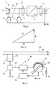
- the in Fig. 1 sketched AC generator 1 has as a DC power source, a photovoltaic system 2 and a direct current of the photovoltaic system 2 in an alternating current inverter 3 on.
- the alternator 1 feeds power via the inverter 3 into an alternating current network 4.
- a differential current occurring across the outputs of the here single-phase inverter 3, ie via the phase L and the neutral conductor N is detected by a current sum converter 5.
- the differential current could also be detected via the input lines 29 and 30 of the inverter 3, to which the output voltages U PV + and U PV- of the photovoltaic system 2 are applied, as indicated by a further dashed-line current summation converter 5 '.
- Such a differential current has two main causes.
- a leakage current which is based on discharge capacitances 6 and 7 of the photovoltaic system 2 with respect to ground, which in Fig. 1 between the inputs of the inverter 3 for U PV + and U PV and the ground potential PE are indicated.
- a fault current component of the differential current which in Fig. 1 are arranged by resistors 8 and 9 between the inputs of the inverter 3 and ground potential PE, which stand for the insulation resistance of these inputs. With intact isolation, the resistors 8 and 9 are very large, and accordingly, the fault current component of the differential current is small.
- An insulation fault is associated with an increase in the fault current component of the differential current. It is important to recognize such an increase because every insulation fault is a source of danger. The detection of the increase of the fault current component The differential current must also be reliable if it takes place in the presence of a high leakage current component of the differential current, which indicates no fault condition.
- Fig. 2 outlines the composition of the differential current DI from the fault current component FI and the Ableitstromanteil AI, wherein the fault current component FI and Ableitstromanteil AI add vectorially to the differential current DI, since the fault current component FI is a resistive current and the Ableitstromanteil AI is a capacitive current.
- Out Fig. 2 shows that with increasing Ableitstromanteil AI an increase of the fault current component FI by a certain amount has a diminishing effect on the amount of the differential current DI and thus its effective value. It is therefore of interest to separate the Ableitstromanteil AI from the differential current DI or to compensate for the differential current DI to observe the fault current component FI.
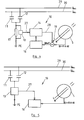
- Fig. 3 sketched device 10 for determining the fault current component of the differential current.
- Capacities 6 and 7 according to Fig. 1 Measuring capacitors 11 and 12 are connected in parallel and a current flowing through these capacitors 11 and 12 to earth (ground potential) PE current is measured by a current measuring device 13.
- the current measurement value is multiplied in a scaling device 14 by multiplication by a scaling factor in order to take into account that the measuring capacitors 11 and 12 represent only a fraction of the total dissipation capacitance of the photovoltaic system 2 according to FIG Fig. 1 represent and so only a fraction of the total Ableitstromanteils AI flows over them.
- the amplified current is then passed in the opposite direction to the conductors L and N by the current sum converter 5, so that it is subtracted directly from the differential current between the L-conductor and the neutral conductor.
- the multiple turns around the summation current transformer 5 of the amplified current-carrying conductor 15 thereby cause an upward scaling of the amplified current, which is included in the effective scaling factor of a scaled electrical signal 28.
- the amplified current ultimately flows through a resistor to earth potential PE.
- the detected by the summation current transformer 5 differential current DI is substantially exempt from the Ableitstromanteil AI and therefore corresponds to its fault current component FI.
- the scaling device 14 can also directly amplify the leakage current flowing off via the measuring capacitors 11 and 12 to ground potential PE and then supply it to the summation current transformer 5.
- a direct compensation of the Ableitstromanteils AI of the differential current DI by a current through the summation current transformer 5 is carried out according to Fig. 4 a compensation of Ableitstromanteils AI by a voltage.
- This is realized here in that the voltage dropping across a measuring resistor 17 due to the leakage current flowing through the measuring capacitors 11 and 12 to earth potential is detected by a voltage measuring device 18. This voltage is multiplied by the scaling factor by the scaling device 14 and then subtracted as a scaled electrical signal 28 in a subtraction node 19 from the voltage signal of the summation current transformer 5.
- the signal is provided to the current measuring device 13 directly to the logic 16, which digitizes it and appropriately scales it to subtract it from the digitized signal of the summation current transformer 5.
- the scaling factor is chosen so that the effective value of the remaining differential current DI, which corresponds to its fault current component FI, assumes a minimum.
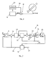
- the advantage of the embodiments of the device 10 according to the Fig. 3 to 5 is that by the leakage current through the measuring capacitors 11 and 12 against ground potential or the voltages thereof caused an electrical signal is available, which has the same phase and frequency distribution as the Ableitstromanteil AI of the differential current DI.
- the leakage current through the measuring capacitors 11 and 12 differs from the Ableitstromanteil AI of the differential current DI only in terms of its amplitude. However, this can be adjusted by means of the scaling factor, which satisfies the criterion of minimizing the effective value of the differential current DI after subtraction of the scaled leakage current. This applies regardless of which frequency components of the leakage current in the current mode of operation of the inverter 3 according to Fig. 1 or due to other influencing factors.
- Fig. 6 outlines the compensation of only one main component of Ableitstromanteils AI to the differential current DI by means of one of a sine wave generator 20 with a main frequency of the leakage current generated sinusoidal signal.
- the logic 16 operates to minimize the effective value of the differential current DI remaining after the subtraction node 19, both by adjusting the amplitude and the phase of the sine signal. If the leakage current essentially has a frequency, the leakage current component AI at the differential current DI can also be reduced in a meaningful manner in this way.
Landscapes
- Engineering & Computer Science (AREA)
- Power Engineering (AREA)
- Emergency Protection Circuit Devices (AREA)
- Testing Of Short-Circuits, Discontinuities, Leakage, Or Incorrect Line Connections (AREA)
- Inverter Devices (AREA)
- Control Of Eletrric Generators (AREA)
- Measurement Of Resistance Or Impedance (AREA)
Priority Applications (8)
| Application Number | Priority Date | Filing Date | Title |
|---|---|---|---|
| ES10158654.3T ES2565005T3 (es) | 2010-03-31 | 2010-03-31 | Determinación de la parte de corriente de falta de una corriente diferencial |
| EP10158654.3A EP2372857B1 (de) | 2010-03-31 | 2010-03-31 | Bestimmung des Fehlerstromanteils eines Differenzstroms |
| PCT/EP2011/054976 WO2011121056A1 (en) | 2010-03-31 | 2011-03-31 | Determination of the fault current component of a differential current |
| CA2794116A CA2794116A1 (en) | 2010-03-31 | 2011-03-31 | Determination of the fault current component of a differential current |
| CN201180016409.7A CN102834992B (zh) | 2010-03-31 | 2011-03-31 | 差动电流的故障电流分量的确定 |
| JP2013501842A JP5672369B2 (ja) | 2010-03-31 | 2011-03-31 | 差動電流の故障電流成分の決定 |
| US13/628,174 US9350162B2 (en) | 2010-03-31 | 2012-09-27 | Determination of the fault current component of a differential current |
| US13/944,940 US20130300428A1 (en) | 2010-03-31 | 2013-07-18 | Determination of a Stray Capacitance of an AC Current Generator |
Applications Claiming Priority (1)
| Application Number | Priority Date | Filing Date | Title |
|---|---|---|---|
| EP10158654.3A EP2372857B1 (de) | 2010-03-31 | 2010-03-31 | Bestimmung des Fehlerstromanteils eines Differenzstroms |
Publications (3)
| Publication Number | Publication Date |
|---|---|
| EP2372857A1 EP2372857A1 (de) | 2011-10-05 |
| EP2372857A8 EP2372857A8 (de) | 2011-11-30 |
| EP2372857B1 true EP2372857B1 (de) | 2015-10-07 |
Family
ID=42342725
Family Applications (1)
| Application Number | Title | Priority Date | Filing Date |
|---|---|---|---|
| EP10158654.3A Active EP2372857B1 (de) | 2010-03-31 | 2010-03-31 | Bestimmung des Fehlerstromanteils eines Differenzstroms |
Country Status (7)
Families Citing this family (29)
| Publication number | Priority date | Publication date | Assignee | Title |
|---|---|---|---|---|
| DE102010013642B4 (de) | 2010-04-01 | 2022-01-20 | Doepke Schaltgeräte GmbH | Verfahren zum Kompensieren von Ableitströmen und Differenzstromschutz- oderÜberwachungseinrichtung |
| US9013060B2 (en) * | 2010-04-30 | 2015-04-21 | Infosys Limited | Method and system for measuring, monitoring and controlling electrical power consumption |
| DE102011002084A1 (de) | 2011-04-15 | 2012-10-18 | Sma Solar Technology Ag | Verfahren und Vorrichtung zur Bestimmung eines Fehlerstromanteils an einem Differenzstrom |
| CN102437548A (zh) * | 2011-12-30 | 2012-05-02 | 邹溪 | 一种零剩余电流保护电路方法及其剩余电流保护断路器 |
| DE102012016696A1 (de) * | 2012-06-06 | 2013-12-12 | Diehl Ako Stiftung & Co. Kg | Schaltungsanordnung und Verfahren zur Gleichstromunterbrechung |
| JP6195091B2 (ja) | 2012-08-03 | 2017-09-13 | エスエムエー ソーラー テクノロジー エージー | 漏洩電流および故障電流の分散型検知、ならびにストリング故障の検知 |
| EP2923213B1 (de) * | 2012-11-21 | 2016-11-02 | SMA Solar Technology AG | Isolationsmessverfahren für trafolose wechselrichter |
| CN105359364B (zh) * | 2013-07-18 | 2018-04-17 | 艾思玛太阳能技术股份公司 | 方法、电路安排和具有在带差值电流传感器的光伏设备中用于泄漏电流补偿的器件的光伏逆变器 |
| WO2015075821A1 (ja) * | 2013-11-22 | 2015-05-28 | 三菱電機株式会社 | 絶縁検出器及び電気機器 |
| DE102013113000A1 (de) | 2013-11-25 | 2015-05-28 | Sma Solar Technology Ag | Verfahren zum Betreiben eines Wechselrichters und Wechselrichter mit einem Schalter zwischen einem Mittelpunkt eines Gleichspannungszwischenkreises und einem Anschluss für einen Nullleiter eines Wechselstromnetzes |
| DE102013227174B4 (de) * | 2013-12-27 | 2019-06-19 | Fronius International Gmbh | Vorrichtung und Verfahren zur Ermittlung eines Isolationswiderstandes einer Photovoltaikanlage |
| DE102015101870A1 (de) | 2014-02-11 | 2015-08-13 | Sma Solar Technology Ag | Verfahren zur Kompensation eines über eine Ableitkapazität fließenden Anteils an einem Differenzstrom und zur Durchführung des Verfahrens geeigneter Wechselrichter |
| JP6326309B2 (ja) * | 2014-07-02 | 2018-05-16 | ルネサスエレクトロニクス株式会社 | アイソレータ、半導体装置及びアイソレータの制御方法 |
| DE102017129083A1 (de) * | 2017-12-06 | 2019-06-06 | Sma Solar Technology Ag | Fehlabschaltsicheres Betriebsverfahren für eine dezentrale Energieerzeugungsanlage |
| DE102018118259A1 (de) * | 2018-07-27 | 2020-01-30 | Dr. Ing. H.C. F. Porsche Aktiengesellschaft | Verfahren und Vorrichtung zur Reduktion von Ableitströmen |
| CN109361199B (zh) * | 2018-10-10 | 2023-10-20 | 国网浙江省电力有限公司台州供电公司 | 用于光伏电站送出线上过渡电阻接地故障的保护方法 |
| DE102019121961A1 (de) * | 2019-08-15 | 2021-02-18 | Dr. Ing. H.C. F. Porsche Aktiengesellschaft | Kompensationsvorrichtung zur Kompensation von Ableitströmen |
| DE102019126438B4 (de) * | 2019-10-01 | 2021-12-23 | Dr. Ing. H.C. F. Porsche Aktiengesellschaft | Kompensationsvorrichtung für Ableitströme |
| DE102019007224B3 (de) * | 2019-10-17 | 2021-03-25 | SAFETYTEST GmbH | Verfahren und Vorrichtung zum Bestimmen des resistiven Anteils der Ableitstromimpedanz im Wechselstromnetz |
| CN111157777B (zh) * | 2020-01-14 | 2020-11-27 | 清华大学 | 一种双磁芯测量差分泄漏电流传感器设计方法 |
| CN111157776A (zh) * | 2020-01-14 | 2020-05-15 | 清华大学 | 一种电力设备绝缘泄漏电流的双磁芯传感器 |
| DE102020115757A1 (de) | 2020-06-15 | 2021-12-16 | Sma Solar Technology Ag | Vorrichtung und verfahren zur detektion eines fehlerstroms in einer photovoltaik-anlage, sowie photovoltaik-wechselrichter mit der vorrichtung |
| EP4165743A1 (de) | 2020-06-15 | 2023-04-19 | SMA Solar Technology AG | Vorrichtung und verfahren zur detektion eines fehlerstroms in einer photovoltaik-anlage, sowie photovoltaik-wechselrichter mit der vorrichtung |
| DE102020123493A1 (de) | 2020-09-09 | 2022-03-10 | Sma Solar Technology Ag | Vorrichtung und verfahren zur detektion eines fehlerstroms in einer photovoltaik-anlage, sowie photovoltaik-wechselrichter mit der vorrichtung |
| DE102020119106B3 (de) | 2020-07-21 | 2021-11-25 | Dr. Ing. H.C. F. Porsche Aktiengesellschaft | Vorrichtung zur Erzeugung eines Kompensationsstroms |
| DE102020131512A1 (de) | 2020-11-27 | 2022-06-02 | Dr. Ing. H.C. F. Porsche Aktiengesellschaft | Vorrichtung zur Erzeugung eines Kompensationsstroms |
| US11411385B2 (en) * | 2020-12-03 | 2022-08-09 | Kedu Electric Co., Ltd. | Timing leakage protection circuit and device containing same |
| EP4123326B1 (de) * | 2021-07-23 | 2024-05-01 | A. Eberle GmbH & Co. Kg | Verfahren zur rekonstruktion von fehlerstrom und ableitstrom aus dem differenzstrom von oder in mehrleitersystemen |
| DE102022131311A1 (de) * | 2022-11-28 | 2024-05-29 | Dr. Ing. H.C. F. Porsche Aktiengesellschaft | Verfahren und Vorrichtung zur Kompensation von Ableitströmen in einem elektrischen Leistungswandler |
Family Cites Families (17)
| Publication number | Priority date | Publication date | Assignee | Title |
|---|---|---|---|---|
| US4138707A (en) | 1977-07-21 | 1979-02-06 | Gross Thomas A O | Ground fault protective systems with predetection neutralization of reactive currents |
| US4837519A (en) | 1985-09-06 | 1989-06-06 | Southern California Edison Company | Fault detection |
| US6055145A (en) * | 1990-12-28 | 2000-04-25 | Eaton Corporation | Overcurrent protection device with visual indicators for trip and programming functions |
| GB9514528D0 (en) * | 1995-07-15 | 1995-09-13 | Smiths Industries Plc | Electrical apparatus |
| JPH10322885A (ja) | 1997-05-14 | 1998-12-04 | Canon Inc | 太陽光発電装置 |
| DE59807747D1 (de) | 1997-06-17 | 2003-05-08 | Walther Bender Gmbh & Co Kg Di | Verfahren und einrichtung zur isolations- und fehlerstromüberwachung in einem elektrischen wechselstromnetz |
| US6172509B1 (en) * | 1999-02-11 | 2001-01-09 | The United States Of America As Represented By The Secretary Of The Air Force | Detecting polyphase machine faults via current deviation |
| US6625551B1 (en) * | 2000-06-09 | 2003-09-23 | Siemens Aktiengesellschaft | Fault current and differential current detection system capable of preventing spurious triggering of a protection system due to transient interference pulses |
| JP2002233045A (ja) * | 2001-02-02 | 2002-08-16 | Canon Inc | 太陽光発電システムの地絡検出のための装置及び方法 |
| JP2003098215A (ja) * | 2001-09-26 | 2003-04-03 | Canon Inc | 電力変換システムにおける地絡検出のための装置及び方法 |
| DE10253864B4 (de) * | 2002-11-15 | 2005-04-21 | Siemens Ag | Verfahren und Anordnung zur Erdschlussüberwachung eines Stators in Sternschaltung |
| JP3966251B2 (ja) * | 2003-08-08 | 2007-08-29 | オムロン株式会社 | 直流電流検出回路及び直流地絡電流検出回路 |
| US20080077336A1 (en) | 2006-09-25 | 2008-03-27 | Roosevelt Fernandes | Power line universal monitor |
| JP2008164375A (ja) * | 2006-12-27 | 2008-07-17 | Sbc Co Ltd | 電気機器における漏洩電流測定装置及び漏洩電流測定方法 |
| US8022710B2 (en) * | 2008-01-18 | 2011-09-20 | GM Global Technology Operations LLC | Methods for common mode voltage-based AC fault detection, verification and/or identification |
| US8023245B2 (en) | 2008-10-13 | 2011-09-20 | Hamilton Sundstrand Corporation | Lightning strike mitigation for aircraft |
| US20130300428A1 (en) | 2010-03-31 | 2013-11-14 | Sma Solar Technology Ag | Determination of a Stray Capacitance of an AC Current Generator |
-
2010
- 2010-03-31 ES ES10158654.3T patent/ES2565005T3/es active Active
- 2010-03-31 EP EP10158654.3A patent/EP2372857B1/de active Active
-
2011
- 2011-03-31 WO PCT/EP2011/054976 patent/WO2011121056A1/en active Application Filing
- 2011-03-31 CA CA2794116A patent/CA2794116A1/en not_active Abandoned
- 2011-03-31 CN CN201180016409.7A patent/CN102834992B/zh active Active
- 2011-03-31 JP JP2013501842A patent/JP5672369B2/ja active Active
-
2012
- 2012-09-27 US US13/628,174 patent/US9350162B2/en active Active
Also Published As
| Publication number | Publication date |
|---|---|
| JP5672369B2 (ja) | 2015-02-18 |
| EP2372857A1 (de) | 2011-10-05 |
| JP2013527738A (ja) | 2013-06-27 |
| WO2011121056A1 (en) | 2011-10-06 |
| EP2372857A8 (de) | 2011-11-30 |
| CA2794116A1 (en) | 2011-10-06 |
| US20130043880A1 (en) | 2013-02-21 |
| CN102834992B (zh) | 2015-03-25 |
| CN102834992A (zh) | 2012-12-19 |
| ES2565005T3 (es) | 2016-03-30 |
| US9350162B2 (en) | 2016-05-24 |
Similar Documents
| Publication | Publication Date | Title |
|---|---|---|
| EP2372857B1 (de) | Bestimmung des Fehlerstromanteils eines Differenzstroms | |
| EP2230522B1 (de) | Verfahren und Vorrichtung zur Isolationsüberwachung eines Netzes ohne Neutralleiter | |
| EP2256506B1 (de) | Verfahren und Vorrichtung zur Isolationsüberwachung von ungeerdeten Gleich- und Wechselspannungsnetzen | |
| DE112012001189B4 (de) | Verfahren, Systeme und Einrichtungen zum Erkennen paralleler elektrischer Fehlerlichtbögen | |
| EP2697661B1 (de) | Verfahren und vorrichtung zur bestimmung eines fehlerstromanteils an einem differenzstrom | |
| EP3598151B1 (de) | Verfahren und vorrichtung zur bestimmung der aufteilung eines gesamt-isolationswiderstands und der aufteilung einer gesamt-netzableitkapazität in einem ungeerdeten stromversorgungssystem | |
| EP3022814B1 (de) | Verfahren und schaltungsanordnung mit mitteln zur ableitstromkompensation in einer photovoltaikanlage mit mehreren differenzstromsensoren | |
| EP3059828B1 (de) | Vorrichtung und verfahren zur fehlerstromdetektion | |
| DE112010002226T5 (de) | Verfahren und Vorrichtungen zur Erdschlussüberwachung mittels Multifrequenz-Fehlerstromschutzschalter | |
| DE102020102726B3 (de) | Verfahren zur Überwachung eines Erdwiderstands einer elektrischen Anlage | |
| EP2863553B1 (de) | Koppeleinrichtung zum Ankoppeln eines Powerline-Endgeräts und eines Messgeräts an ein Energieversorgungsnetzwerk sowie Messknoten | |
| EP3069359B1 (de) | Verfahren und vorrichtung zur überwachung von kondensatordurchführungen für ein dreiphasiges wechselstromnetz | |
| EP1664804B1 (de) | Verfahren und vorrichtung zur spannungsmessung | |
| EP3870982A1 (de) | Verfahren zur isolationswiderstandsmessung in wechselrichtern mit mehrpunkttopologie und wechselrichter mit mehrpunkttopologie | |
| DE102013106702A1 (de) | Verfahren und Vorrichtung zum Erkennen eines Lichtbogens | |
| DE102017116613B3 (de) | Verfahren und Prüfvorrichtung zur Messung von Teilentladungsimpulsen eines geschirmten Kabels | |
| AT402770B (de) | Verfahren zum überwachen eines drehstromnetzes auf eine abstimmungsänderung der erdschlusslöschspule | |
| DE102010013642A1 (de) | Verfahren zum Kompensieren von insbesondere durch Kapazitäten hervorgerufenen Ableitströmen und Differenzstromschutz- oder Überwachungseinrichtung | |
| EP3876406A1 (de) | Verfahren und vorrichtung zur kompensation eines ableitstroms in einem emv-filter | |
| DE102008024348B4 (de) | Verfahren zur Reduktion pulsförmiger Erdströme an einem elektrischen Großgerät und Kompensationsschaltung zur Erdstromverlagerung | |
| EP2869072A1 (de) | Einrichtung und Verfahren zur Erfassung der elektrischen Energie von ein- oder mehrphasigen Verbrauchern | |
| DE102019132071B4 (de) | Vorrichtung zum Überwachen eines Versorgungsnetzes | |
| DE102011082554B4 (de) | Verfahren zur Bestimmung eines Erdschlussstroms in einem erdschlussbehafteten Drehstromnetz | |
| DE102020004825A1 (de) | Vorrichtung und Verfahren zur Kompensation von Ableitströmen beim Laden eines elektrischen Energiespeichers | |
| DE102015101870A1 (de) | Verfahren zur Kompensation eines über eine Ableitkapazität fließenden Anteils an einem Differenzstrom und zur Durchführung des Verfahrens geeigneter Wechselrichter |
Legal Events
| Date | Code | Title | Description |
|---|---|---|---|
| PUAI | Public reference made under article 153(3) epc to a published international application that has entered the european phase |
Free format text: ORIGINAL CODE: 0009012 |
|
| AK | Designated contracting states |
Kind code of ref document: A1 Designated state(s): AT BE BG CH CY CZ DE DK EE ES FI FR GB GR HR HU IE IS IT LI LT LU LV MC MK MT NL NO PL PT RO SE SI SK SM TR |
|
| RIN1 | Information on inventor provided before grant (corrected) |
Inventor name: PROEVE, OLAF Inventor name: EIDENMUELLER, LUTZ Inventor name: BIENIEK, SEBASTIAN Inventor name: BETTENWORT, GERD |
|
| 17P | Request for examination filed |
Effective date: 20120317 |
|
| RIN1 | Information on inventor provided before grant (corrected) |
Inventor name: BETTENWORT, GERD Inventor name: EIDENMUELLER, LUTZ Inventor name: PROEVE, OLAF Inventor name: BIENIEK, SEBASTIAN |
|
| 17Q | First examination report despatched |
Effective date: 20150303 |
|
| GRAP | Despatch of communication of intention to grant a patent |
Free format text: ORIGINAL CODE: EPIDOSNIGR1 |
|
| INTG | Intention to grant announced |
Effective date: 20150429 |
|
| GRAS | Grant fee paid |
Free format text: ORIGINAL CODE: EPIDOSNIGR3 |
|
| GRAA | (expected) grant |
Free format text: ORIGINAL CODE: 0009210 |
|
| AK | Designated contracting states |
Kind code of ref document: B1 Designated state(s): AT BE BG CH CY CZ DE DK EE ES FI FR GB GR HR HU IE IS IT LI LT LU LV MC MK MT NL NO PL PT RO SE SI SK SM TR |
|
| REG | Reference to a national code |
Ref country code: GB Ref legal event code: FG4D Free format text: NOT ENGLISH |
|
| REG | Reference to a national code |
Ref country code: AT Ref legal event code: REF Ref document number: 754250 Country of ref document: AT Kind code of ref document: T Effective date: 20151015 Ref country code: CH Ref legal event code: EP |
|
| REG | Reference to a national code |
Ref country code: IE Ref legal event code: FG4D Free format text: LANGUAGE OF EP DOCUMENT: GERMAN |
|
| REG | Reference to a national code |
Ref country code: DE Ref legal event code: R096 Ref document number: 502010010405 Country of ref document: DE |
|
| REG | Reference to a national code |
Ref country code: NL Ref legal event code: MP Effective date: 20151007 |
|
| REG | Reference to a national code |
Ref country code: LT Ref legal event code: MG4D |
|
| REG | Reference to a national code |
Ref country code: FR Ref legal event code: PLFP Year of fee payment: 7 |
|
| REG | Reference to a national code |
Ref country code: ES Ref legal event code: FG2A Ref document number: 2565005 Country of ref document: ES Kind code of ref document: T3 Effective date: 20160330 |
|
| PG25 | Lapsed in a contracting state [announced via postgrant information from national office to epo] |
Ref country code: LT Free format text: LAPSE BECAUSE OF FAILURE TO SUBMIT A TRANSLATION OF THE DESCRIPTION OR TO PAY THE FEE WITHIN THE PRESCRIBED TIME-LIMIT Effective date: 20151007 Ref country code: NO Free format text: LAPSE BECAUSE OF FAILURE TO SUBMIT A TRANSLATION OF THE DESCRIPTION OR TO PAY THE FEE WITHIN THE PRESCRIBED TIME-LIMIT Effective date: 20160107 Ref country code: HR Free format text: LAPSE BECAUSE OF FAILURE TO SUBMIT A TRANSLATION OF THE DESCRIPTION OR TO PAY THE FEE WITHIN THE PRESCRIBED TIME-LIMIT Effective date: 20151007 Ref country code: NL Free format text: LAPSE BECAUSE OF FAILURE TO SUBMIT A TRANSLATION OF THE DESCRIPTION OR TO PAY THE FEE WITHIN THE PRESCRIBED TIME-LIMIT Effective date: 20151007 Ref country code: IS Free format text: LAPSE BECAUSE OF FAILURE TO SUBMIT A TRANSLATION OF THE DESCRIPTION OR TO PAY THE FEE WITHIN THE PRESCRIBED TIME-LIMIT Effective date: 20160207 |
|
| PG25 | Lapsed in a contracting state [announced via postgrant information from national office to epo] |
Ref country code: LV Free format text: LAPSE BECAUSE OF FAILURE TO SUBMIT A TRANSLATION OF THE DESCRIPTION OR TO PAY THE FEE WITHIN THE PRESCRIBED TIME-LIMIT Effective date: 20151007 Ref country code: SE Free format text: LAPSE BECAUSE OF FAILURE TO SUBMIT A TRANSLATION OF THE DESCRIPTION OR TO PAY THE FEE WITHIN THE PRESCRIBED TIME-LIMIT Effective date: 20151007 Ref country code: PT Free format text: LAPSE BECAUSE OF FAILURE TO SUBMIT A TRANSLATION OF THE DESCRIPTION OR TO PAY THE FEE WITHIN THE PRESCRIBED TIME-LIMIT Effective date: 20160208 Ref country code: FI Free format text: LAPSE BECAUSE OF FAILURE TO SUBMIT A TRANSLATION OF THE DESCRIPTION OR TO PAY THE FEE WITHIN THE PRESCRIBED TIME-LIMIT Effective date: 20151007 Ref country code: GR Free format text: LAPSE BECAUSE OF FAILURE TO SUBMIT A TRANSLATION OF THE DESCRIPTION OR TO PAY THE FEE WITHIN THE PRESCRIBED TIME-LIMIT Effective date: 20160108 Ref country code: PL Free format text: LAPSE BECAUSE OF FAILURE TO SUBMIT A TRANSLATION OF THE DESCRIPTION OR TO PAY THE FEE WITHIN THE PRESCRIBED TIME-LIMIT Effective date: 20151007 |
|
| REG | Reference to a national code |
Ref country code: DE Ref legal event code: R097 Ref document number: 502010010405 Country of ref document: DE |
|
| PG25 | Lapsed in a contracting state [announced via postgrant information from national office to epo] |
Ref country code: CZ Free format text: LAPSE BECAUSE OF FAILURE TO SUBMIT A TRANSLATION OF THE DESCRIPTION OR TO PAY THE FEE WITHIN THE PRESCRIBED TIME-LIMIT Effective date: 20151007 |
|
| PLBE | No opposition filed within time limit |
Free format text: ORIGINAL CODE: 0009261 |
|
| STAA | Information on the status of an ep patent application or granted ep patent |
Free format text: STATUS: NO OPPOSITION FILED WITHIN TIME LIMIT |
|
| PG25 | Lapsed in a contracting state [announced via postgrant information from national office to epo] |
Ref country code: EE Free format text: LAPSE BECAUSE OF FAILURE TO SUBMIT A TRANSLATION OF THE DESCRIPTION OR TO PAY THE FEE WITHIN THE PRESCRIBED TIME-LIMIT Effective date: 20151007 Ref country code: DK Free format text: LAPSE BECAUSE OF FAILURE TO SUBMIT A TRANSLATION OF THE DESCRIPTION OR TO PAY THE FEE WITHIN THE PRESCRIBED TIME-LIMIT Effective date: 20151007 Ref country code: BE Free format text: LAPSE BECAUSE OF NON-PAYMENT OF DUE FEES Effective date: 20160331 Ref country code: SM Free format text: LAPSE BECAUSE OF FAILURE TO SUBMIT A TRANSLATION OF THE DESCRIPTION OR TO PAY THE FEE WITHIN THE PRESCRIBED TIME-LIMIT Effective date: 20151007 Ref country code: SK Free format text: LAPSE BECAUSE OF FAILURE TO SUBMIT A TRANSLATION OF THE DESCRIPTION OR TO PAY THE FEE WITHIN THE PRESCRIBED TIME-LIMIT Effective date: 20151007 Ref country code: RO Free format text: LAPSE BECAUSE OF FAILURE TO SUBMIT A TRANSLATION OF THE DESCRIPTION OR TO PAY THE FEE WITHIN THE PRESCRIBED TIME-LIMIT Effective date: 20151007 |
|
| 26N | No opposition filed |
Effective date: 20160708 |
|
| PG25 | Lapsed in a contracting state [announced via postgrant information from national office to epo] |
Ref country code: LU Free format text: LAPSE BECAUSE OF FAILURE TO SUBMIT A TRANSLATION OF THE DESCRIPTION OR TO PAY THE FEE WITHIN THE PRESCRIBED TIME-LIMIT Effective date: 20160331 Ref country code: MC Free format text: LAPSE BECAUSE OF FAILURE TO SUBMIT A TRANSLATION OF THE DESCRIPTION OR TO PAY THE FEE WITHIN THE PRESCRIBED TIME-LIMIT Effective date: 20151007 |
|
| REG | Reference to a national code |
Ref country code: CH Ref legal event code: PL |
|
| PG25 | Lapsed in a contracting state [announced via postgrant information from national office to epo] |
Ref country code: SI Free format text: LAPSE BECAUSE OF FAILURE TO SUBMIT A TRANSLATION OF THE DESCRIPTION OR TO PAY THE FEE WITHIN THE PRESCRIBED TIME-LIMIT Effective date: 20151007 |
|
| REG | Reference to a national code |
Ref country code: IE Ref legal event code: MM4A |
|
| PG25 | Lapsed in a contracting state [announced via postgrant information from national office to epo] |
Ref country code: CH Free format text: LAPSE BECAUSE OF NON-PAYMENT OF DUE FEES Effective date: 20160331 Ref country code: LI Free format text: LAPSE BECAUSE OF NON-PAYMENT OF DUE FEES Effective date: 20160331 Ref country code: IE Free format text: LAPSE BECAUSE OF NON-PAYMENT OF DUE FEES Effective date: 20160331 |
|
| REG | Reference to a national code |
Ref country code: FR Ref legal event code: PLFP Year of fee payment: 8 |
|
| REG | Reference to a national code |
Ref country code: AT Ref legal event code: MM01 Ref document number: 754250 Country of ref document: AT Kind code of ref document: T Effective date: 20160331 |
|
| PG25 | Lapsed in a contracting state [announced via postgrant information from national office to epo] |
Ref country code: MT Free format text: LAPSE BECAUSE OF FAILURE TO SUBMIT A TRANSLATION OF THE DESCRIPTION OR TO PAY THE FEE WITHIN THE PRESCRIBED TIME-LIMIT Effective date: 20151007 Ref country code: AT Free format text: LAPSE BECAUSE OF NON-PAYMENT OF DUE FEES Effective date: 20160331 |
|
| REG | Reference to a national code |
Ref country code: FR Ref legal event code: PLFP Year of fee payment: 9 |
|
| PG25 | Lapsed in a contracting state [announced via postgrant information from national office to epo] |
Ref country code: CY Free format text: LAPSE BECAUSE OF FAILURE TO SUBMIT A TRANSLATION OF THE DESCRIPTION OR TO PAY THE FEE WITHIN THE PRESCRIBED TIME-LIMIT Effective date: 20151007 Ref country code: HU Free format text: LAPSE BECAUSE OF FAILURE TO SUBMIT A TRANSLATION OF THE DESCRIPTION OR TO PAY THE FEE WITHIN THE PRESCRIBED TIME-LIMIT; INVALID AB INITIO Effective date: 20100331 |
|
| PG25 | Lapsed in a contracting state [announced via postgrant information from national office to epo] |
Ref country code: MK Free format text: LAPSE BECAUSE OF FAILURE TO SUBMIT A TRANSLATION OF THE DESCRIPTION OR TO PAY THE FEE WITHIN THE PRESCRIBED TIME-LIMIT Effective date: 20151007 Ref country code: TR Free format text: LAPSE BECAUSE OF FAILURE TO SUBMIT A TRANSLATION OF THE DESCRIPTION OR TO PAY THE FEE WITHIN THE PRESCRIBED TIME-LIMIT Effective date: 20151007 |
|
| PG25 | Lapsed in a contracting state [announced via postgrant information from national office to epo] |
Ref country code: BG Free format text: LAPSE BECAUSE OF FAILURE TO SUBMIT A TRANSLATION OF THE DESCRIPTION OR TO PAY THE FEE WITHIN THE PRESCRIBED TIME-LIMIT Effective date: 20151007 |
|
| PGFP | Annual fee paid to national office [announced via postgrant information from national office to epo] |
Ref country code: DE Payment date: 20250319 Year of fee payment: 16 |
|
| PGFP | Annual fee paid to national office [announced via postgrant information from national office to epo] |
Ref country code: FR Payment date: 20250324 Year of fee payment: 16 |
|
| PGFP | Annual fee paid to national office [announced via postgrant information from national office to epo] |
Ref country code: GB Payment date: 20250324 Year of fee payment: 16 |
|
| PGFP | Annual fee paid to national office [announced via postgrant information from national office to epo] |
Ref country code: ES Payment date: 20250416 Year of fee payment: 16 |
|
| PGFP | Annual fee paid to national office [announced via postgrant information from national office to epo] |
Ref country code: IT Payment date: 20250331 Year of fee payment: 16 |