EP2372815A1 - Positive electrode tab lead, negative electrode tab lead, and battery - Google Patents
Positive electrode tab lead, negative electrode tab lead, and battery Download PDFInfo
- Publication number
- EP2372815A1 EP2372815A1 EP09834631A EP09834631A EP2372815A1 EP 2372815 A1 EP2372815 A1 EP 2372815A1 EP 09834631 A EP09834631 A EP 09834631A EP 09834631 A EP09834631 A EP 09834631A EP 2372815 A1 EP2372815 A1 EP 2372815A1
- Authority
- EP
- European Patent Office
- Prior art keywords
- tab lead
- coating layer
- positive
- aluminum plate
- negative
- Prior art date
- Legal status (The legal status is an assumption and is not a legal conclusion. Google has not performed a legal analysis and makes no representation as to the accuracy of the status listed.)
- Withdrawn
Links
Images


Classifications
-
- H—ELECTRICITY
- H01—ELECTRIC ELEMENTS
- H01M—PROCESSES OR MEANS, e.g. BATTERIES, FOR THE DIRECT CONVERSION OF CHEMICAL ENERGY INTO ELECTRICAL ENERGY
- H01M50/00—Constructional details or processes of manufacture of the non-active parts of electrochemical cells other than fuel cells, e.g. hybrid cells
- H01M50/50—Current conducting connections for cells or batteries
- H01M50/543—Terminals
-
- H—ELECTRICITY
- H01—ELECTRIC ELEMENTS
- H01M—PROCESSES OR MEANS, e.g. BATTERIES, FOR THE DIRECT CONVERSION OF CHEMICAL ENERGY INTO ELECTRICAL ENERGY
- H01M50/00—Constructional details or processes of manufacture of the non-active parts of electrochemical cells other than fuel cells, e.g. hybrid cells
- H01M50/50—Current conducting connections for cells or batteries
- H01M50/571—Methods or arrangements for affording protection against corrosion; Selection of materials therefor
-
- H—ELECTRICITY
- H01—ELECTRIC ELEMENTS
- H01M—PROCESSES OR MEANS, e.g. BATTERIES, FOR THE DIRECT CONVERSION OF CHEMICAL ENERGY INTO ELECTRICAL ENERGY
- H01M10/00—Secondary cells; Manufacture thereof
- H01M10/05—Accumulators with non-aqueous electrolyte
- H01M10/052—Li-accumulators
-
- H—ELECTRICITY
- H01—ELECTRIC ELEMENTS
- H01M—PROCESSES OR MEANS, e.g. BATTERIES, FOR THE DIRECT CONVERSION OF CHEMICAL ENERGY INTO ELECTRICAL ENERGY
- H01M50/00—Constructional details or processes of manufacture of the non-active parts of electrochemical cells other than fuel cells, e.g. hybrid cells
- H01M50/10—Primary casings; Jackets or wrappings
- H01M50/172—Arrangements of electric connectors penetrating the casing
-
- H—ELECTRICITY
- H01—ELECTRIC ELEMENTS
- H01M—PROCESSES OR MEANS, e.g. BATTERIES, FOR THE DIRECT CONVERSION OF CHEMICAL ENERGY INTO ELECTRICAL ENERGY
- H01M50/00—Constructional details or processes of manufacture of the non-active parts of electrochemical cells other than fuel cells, e.g. hybrid cells
- H01M50/10—Primary casings; Jackets or wrappings
- H01M50/172—Arrangements of electric connectors penetrating the casing
- H01M50/174—Arrangements of electric connectors penetrating the casing adapted for the shape of the cells
- H01M50/176—Arrangements of electric connectors penetrating the casing adapted for the shape of the cells for prismatic or rectangular cells
-
- H—ELECTRICITY
- H01—ELECTRIC ELEMENTS
- H01M—PROCESSES OR MEANS, e.g. BATTERIES, FOR THE DIRECT CONVERSION OF CHEMICAL ENERGY INTO ELECTRICAL ENERGY
- H01M50/00—Constructional details or processes of manufacture of the non-active parts of electrochemical cells other than fuel cells, e.g. hybrid cells
- H01M50/50—Current conducting connections for cells or batteries
- H01M50/531—Electrode connections inside a battery casing
-
- H—ELECTRICITY
- H01—ELECTRIC ELEMENTS
- H01M—PROCESSES OR MEANS, e.g. BATTERIES, FOR THE DIRECT CONVERSION OF CHEMICAL ENERGY INTO ELECTRICAL ENERGY
- H01M50/00—Constructional details or processes of manufacture of the non-active parts of electrochemical cells other than fuel cells, e.g. hybrid cells
- H01M50/50—Current conducting connections for cells or batteries
- H01M50/531—Electrode connections inside a battery casing
- H01M50/533—Electrode connections inside a battery casing characterised by the shape of the leads or tabs
-
- H—ELECTRICITY
- H01—ELECTRIC ELEMENTS
- H01M—PROCESSES OR MEANS, e.g. BATTERIES, FOR THE DIRECT CONVERSION OF CHEMICAL ENERGY INTO ELECTRICAL ENERGY
- H01M50/00—Constructional details or processes of manufacture of the non-active parts of electrochemical cells other than fuel cells, e.g. hybrid cells
- H01M50/50—Current conducting connections for cells or batteries
- H01M50/531—Electrode connections inside a battery casing
- H01M50/534—Electrode connections inside a battery casing characterised by the material of the leads or tabs
-
- H—ELECTRICITY
- H01—ELECTRIC ELEMENTS
- H01M—PROCESSES OR MEANS, e.g. BATTERIES, FOR THE DIRECT CONVERSION OF CHEMICAL ENERGY INTO ELECTRICAL ENERGY
- H01M50/00—Constructional details or processes of manufacture of the non-active parts of electrochemical cells other than fuel cells, e.g. hybrid cells
- H01M50/50—Current conducting connections for cells or batteries
- H01M50/543—Terminals
- H01M50/547—Terminals characterised by the disposition of the terminals on the cells
- H01M50/55—Terminals characterised by the disposition of the terminals on the cells on the same side of the cell
-
- H—ELECTRICITY
- H01—ELECTRIC ELEMENTS
- H01M—PROCESSES OR MEANS, e.g. BATTERIES, FOR THE DIRECT CONVERSION OF CHEMICAL ENERGY INTO ELECTRICAL ENERGY
- H01M50/00—Constructional details or processes of manufacture of the non-active parts of electrochemical cells other than fuel cells, e.g. hybrid cells
- H01M50/50—Current conducting connections for cells or batteries
- H01M50/543—Terminals
- H01M50/552—Terminals characterised by their shape
- H01M50/553—Terminals adapted for prismatic, pouch or rectangular cells
-
- H—ELECTRICITY
- H01—ELECTRIC ELEMENTS
- H01M—PROCESSES OR MEANS, e.g. BATTERIES, FOR THE DIRECT CONVERSION OF CHEMICAL ENERGY INTO ELECTRICAL ENERGY
- H01M50/00—Constructional details or processes of manufacture of the non-active parts of electrochemical cells other than fuel cells, e.g. hybrid cells
- H01M50/50—Current conducting connections for cells or batteries
- H01M50/543—Terminals
- H01M50/562—Terminals characterised by the material
-
- Y—GENERAL TAGGING OF NEW TECHNOLOGICAL DEVELOPMENTS; GENERAL TAGGING OF CROSS-SECTIONAL TECHNOLOGIES SPANNING OVER SEVERAL SECTIONS OF THE IPC; TECHNICAL SUBJECTS COVERED BY FORMER USPC CROSS-REFERENCE ART COLLECTIONS [XRACs] AND DIGESTS
- Y02—TECHNOLOGIES OR APPLICATIONS FOR MITIGATION OR ADAPTATION AGAINST CLIMATE CHANGE
- Y02E—REDUCTION OF GREENHOUSE GAS [GHG] EMISSIONS, RELATED TO ENERGY GENERATION, TRANSMISSION OR DISTRIBUTION
- Y02E60/00—Enabling technologies; Technologies with a potential or indirect contribution to GHG emissions mitigation
- Y02E60/10—Energy storage using batteries
Definitions
- the present invention relates to a positive tab lead and a negative tab lead preferably used as a tab lead for, e.g., a secondary battery, such as, e.g., a lithium battery, or a tab lead for, e.g., a capacitor.
- a secondary battery such as, e.g., a lithium battery
- a tab lead for, e.g., a capacitor.
- the language of "aluminum” is used to mean to include aluminum and its alloys
- the language of “copper” is used to mean to include copper and its alloys.
- the language of "battery” is used to mean to include not only a battery, such as, e.g., a secondary battery but also a capacitor.
- a secondary battery e.g., a nonaqueous electrolyte lithium secondary battery
- a capacitor is provided with a tab lead for taking out electricity.
- a tab lead for taking out electricity.
- an aluminum plate was used as a positive tab lead, and a copper plate was used as a negative tab lead (see Patent Document 1).
- the present invention was made in view of the aforementioned technical background, and aims to provide a positive electrode, a negative electrode, and a battery capable of connecting tab leads with each other with a sufficient connection strength at lower energy cost.
- the present invention provides the following means.
- a positive tab lead characterized in that a partial coating layer made of nickel, tin or solder is formed on at least a part of a region of an aluminum plate to be exposed to an outside of an outer cover.
- a negative tab lead characterized in that a nickel coating layer is formed on an entire surface of a copper plate.
- a negative tab lead characterized in that a nickel coating layer is formed on an entire surface of a copper plate, and a partial coating layer made of tin or solder is formed on at least a part of a region of an outer surface of the nickel coating layer to be exposed to an outside of an outer cover.
- a battery comprising a battery main body including a positive electrode, a negative electrode, and electrolyte, an outer cover enclosing the battery main body therein, a positive tab lead electrically connected to the positive electrode, and a negative tab lead electrically connected to the negative electrode, wherein a part of the positive tab lead is exposed to an outside of the outer cover, and a part of the negative tab lead is exposed to the outside, characterized in that the positive tab lead includes an aluminum plate and a partial coating layer made of nickel, tin or solder formed on at least a part of a region of the aluminum plate exposed to the outside, and the negative tab lead includes a copper plate and a nickel coating layer formed on an entire surface of the copper plate.
- a battery comprising a battery main body including a positive electrode, a negative electrode, and electrolyte, an outer cover enclosing the battery main body therein, a positive tab lead electrically connected to the positive electrode, and a negative tab lead electrically connected to the negative electrode, wherein a part of the positive tab lead is exposed to an outside of the outer cover, and a part of the negative tab lead is exposed to the outside, characterized in that the positive tab lead includes an aluminum plate and a partial coating layer made of nickel formed on at least a part of a region of the aluminum plate exposed to the outside, and the negative tab lead includes a copper plate and a nickel coating layer formed on an entire surface of the copper plate.
- a battery comprising a battery main body including a positive electrode, a negative electrode, and electrolyte, an outer cover enclosing the battery main body therein, a positive tab lead electrically connected to the positive electrode, and a negative tab lead electrically connected to the negative electrode, wherein a part of the positive tab lead is exposed to an outside of the outer cover, and a part of the negative tab lead is exposed to the outside, characterized in that the positive tab lead includes an aluminum plate and a partial coating layer made of tin formed on at least a part of a region of the aluminum plate exposed to the outside, and the negative tab lead includes a copper plate, a nickel coating layer formed on an entire surface of the copper plate, and a partial coating layer made of tin formed on at least a part of an region of the nickel coating layer exposed to the outside.
- a battery comprising a battery main body including a positive electrode, a negative electrode, and electrolyte, an outer cover enclosing the battery main body therein, a positive tab lead electrically connected to the positive electrode, and a negative tab lead electrically connected to the negative electrode, wherein a part of the positive tab lead is exposed to an outside of the outer cover, and a part of the negative tab lead is exposed to the outside, characterized in that the positive tab lead includes an aluminum plate and a partial coating layer made of solder formed on at least a part of a region of the aluminum plate exposed to the outside, and the negative tab lead includes a copper plate, a nickel coating layer formed on an entire surface of the copper plate, and a partial coating layer made of solder formed on at least a part of a region of the nickel coating layer exposed to the outside.
- a partial coating layer made of nickel, tin or solder is formed on at least a part of a region of an aluminum plate to be exposed to an outside of an outer cover. Therefore, it is possible to connect tab leads with each other by soldering. Furthermore, since tab leads can be connected by soldering, the energy cost for the connection can be kept low, which is economically beneficial.
- a surface roughness Ra of the aluminum plate is set to 0.03 to 0.5 ⁇ m, the adhesiveness between the positive tab lead and an insulating tab film can be increased, which can improve the battery endurance reliability.
- a surface roughness Ra of a region of the aluminum plate where the partial coating layer is not formed is set to 0.03 to 0.5 ⁇ m, the adhesiveness between the positive tab lead and an insulating tab film can be increased, which can improve the battery endurance reliability.
- the corrosion resistance of the externally exposed region can be enhanced, which in turn can further improve the battery endurance reliability.
- the side edge face 11a of the region of the aluminum plate to be exposed to the outside of the outer cover can be covered by the partial coating layer 13 (see Fig. 9 ) but is not always required to be covered by the partial coating layer 13 (see Fig. 8 ).
- the invention [4] covers both of these structures.
- a chitosan layer containing one or more compounds selected from a group consisting of chitosan and chitosan derivatives is further formed on a surface of the partial coating layer and the aluminum plate, the adhesiveness between the positive tab lead and an insulating tab film can be further improved, which in turn can further improve the battery endurance reliability.
- tab leads can be connected with each other by soldering with a sufficient connection strength. Furthermore, the connection of tab leads can be performed by soldering, reducing the energy cost for the connection, which is economically beneficial. It should be noted that the side edge face of the copper plate can be covered by the nickel coating layer 22 but is not always required to be covered by the nickel coating layer 22 (see Fig. 5 ). The invention [6] covers both of these structures.
- tab leads can be connected with each other by soldering with a sufficient connection strength. Furthermore, the connection of tab leads can be performed by soldering, reducing the energy cost for the connection, which is economically beneficial. It should be noted that the side edge face of the copper plate can be covered by the nickel coating layer 22 but is not always required to be covered by the nickel coating layer 22 (see Fig. 7 ). The invention [7] covers both of these structures.
- a surface roughness Ra of the nickel coating layer is set to 0.03 to 0.5 ⁇ m, the adhesiveness between the negative tab lead and an insulating tab film can be improved, which in turn can improve the battery endurance reliability.
- a chitosan layer containing one or more compounds selected from a group consisting of chitosan and chitosan derivatives is further formed on the nickel coating layer and/or the partial coating layer, the adhesiveness between the negative tab lead and an insulating tab film can be further improved, which in turn can further improve the battery endurance reliability.
- the positive tab lead includes an aluminum plate and a partial coating layer made of nickel, tin or solder formed on at least a part of a region of the aluminum plate exposed to the outside and the negative tab lead includes a copper plate and a nickel coating layer formed on an entire surface (excluding the side edge face) of the copper plate. Therefore, in the case of forming an assembled battery by electrically connecting battery cells structured mentioned above, for example, the partial coating layer of the positive tab lead of a battery cell and the nickel coating layer of the negative tab lead of another battery cell can be connected with a sufficient connecting strength by soldering. Furthermore, since tab leads can be connected with each other by soldering, the energy cost for the connection can be kept low, which is economically beneficial. It should be noted that the side edge face of the copper plate can be covered by the nickel coating layer 22 (see Fig. 5 ) but is not always required to be covered by the nickel coating layer 22. The invention [10] covers both of these structures.
- the positive tab lead includes an aluminum plate and a partial coating layer made of tin formed on at least a part of a region of the aluminum plate exposed to the outside
- the negative tab lead includes a copper plate, a nickel coating layer formed on an entire surface (excluding the side edge face) of the copper plate, and a partial coating layer made of tin formed on at least a part of a region of the nickel coating layer exposed to the outside. Therefore, in the case of forming an assembled battery by electrically connecting battery cells structured mentioned above, for example, the partial coating layer of the positive tab lead of a battery cell and the nickel coating layer of the negative tab lead of another battery cell can be connected with a sufficient connection strength by soldering.
- the positive tab lead includes an aluminum plate and a partial coating layer made of nickel formed on at least a part of a region of the aluminum plate exposed to the outside
- the negative tab lead includes a copper plate and a nickel coating layer formed on an entire surface (excluding the side edge face) of the copper plate. Therefore, in the case of forming an assembled battery by electrically connecting battery cells structured mentioned above, for example, the partial coating layer of the positive tab lead of a battery cell and the partial coating layer of the negative tab lead of another battery cell can be connected with a sufficient connection strength by soldering. Furthermore, since tab leads can be connected with each other by soldering, the energy cost for the connection can be kept low, which is economically beneficial. It should be noted that the side edge face of the copper plate can be covered by the nickel coating layer 22 (see Fig. 7 ) but is not always required to be covered by the nickel coating layer 22. The invention [12] covers both of these structures.
- the positive tab lead includes an aluminum plate and a partial coating layer made of solder formed on at least a part of a region of the aluminum plate exposed to the outside and the negative tab lead includes a copper plate, a nickel coating layer formed on an entire surface (excluding the side edge face) of the copper plate, and a partial coating layer made of solder formed on at least a part of a region of the nickel coating layer exposed to the outside. Therefore, in the case of forming an assembled battery by electrically connecting battery cells structured mentioned above, for example, the partial coating layer of the positive tab lead of a battery cell and the partial coating layer of the negative tab lead of another battery cell can be connected with a sufficient connection strength by soldering.
- the energy cost for the connection can be kept low, which is economically beneficial.
- the side edge face of the copper plate can be covered by the nickel coating layer 22 (see Fig. 7 ) but is not always required to be covered by the nickel coating layer 22.
- the invention [13] covers both of these structures.
- the partial coating layer is formed on an entire region (excluding the side edge face) of the aluminum plate of the positive electrode exposed to the outside, the corrosion resistance of the externally exposed region can be enhanced, which in turn can further improve the battery endurance reliability.
- the side edge face 11a of the region of the aluminum plate to be exposed to the outside of the outer cover can be covered by the partial coating layer 13 (see Fig. 9 ) but is not always required to be covered by the partial coating layer 13 (see Fig. 8 ).
- the invention [14] covers both of these structures.
- Fig. 1 shows a battery 30 according to an embodiment of the present invention.
- the battery 30 of this first embodiment is a nonaqueous electrolyte lithium secondary battery.
- a film-like positive electrode 33 and a film-like negative electrode 34 are arranged one on the other via a separator 36 in a superimposed manner with a nonaqueous electrolyte 35 interposed between the positive electrode and the negative electrode so that electric charge/discharge can be performed by transmission of lithium ions.
- the battery main body 32 including the positive electrode 33, the negative electrode 34 and the electrolyte 35 is covered by an outer cover 31 in a liquid-tight manner. That is, the battery main body is sealed in the outer cover 31 (see Fig. 1 ).
- a positive tab lead 1 is electrically connected to the positive electrode 33, and a part of the positive tab lead 1 is exposed (i.e., extended) to an outside of the outer cover 31 (see Figs. 1 to 3 ).
- the positive tab lead 1 is a member in which a nickel partial coating layer 13 is formed on a part (tip end portion) of the externally exposed region of the aluminum plate 11 and a chitosan layer 14 containing chitosan is formed on an outermost surface. No nickel coating layer is formed on the region of the aluminum plate 11 to be arranged in the outer cover 31.
- insulating tab films 15 and 15 are adhered to both sides of the longitudinally intermediate region of the positive tab lead 1, and the edge portion of the outer cover 31 is arranged such that the edge portion pinches the insulating tab films 15 and 15.
- the edge portion of the outer cover 31 is sealed by, e.g., heat-sealing.
- a negative tab lead 2 is electrically connected to the negative electrode 34, and a part of the negative tab lead 2 is exposed (i.e., extended) to an outside of the outer cover 31 (see Figs. 1 , 4 and 5 ).
- the negative tab lead 2 is a member in which a nickel coating layer 22 is formed on an entire surface of the copper plate 21 and a chitosan layer 24 containing chitosan is formed on an entire outermost surface of the nickel coating layer 22.
- insulating tab films 25 and 25 are adhered to both sides of the longitudinally intermediate region of the negative tab lead 2, and the edge portion of the outer cover 31 is arranged such that the edge portion pinches the insulating tab films 25 and 25.
- the edge portion of the outer cover 31 is sealed by, e.g., heat-sealing.
- the following structure can be employed. That is, it is acceptable to employ a structure that, in the battery of the aforementioned embodiment, as the positive tab lead 1, a tin partial coating layer 13 is formed on a part (tip end portion) of the externally exposed region of the aluminum plate 11 and a chitosan layer 14 containing chitosan is formed on an outermost surface (see Fig. 3 ), while as the negative tab lead 2, as shown in Figs.
- a nickel coating layer 22 is formed on the entire surface of the cupper plate 21, a tin partial coating layer 23 is formed on a part of the externally exposed region of the nickel coating layer 22, and a chitosan layer 24 containing chitosan is formed on the outermost surface. No tin coating layer is formed on the region of the aluminum plate 11 to be arranged in the outer cover 31.
- insulating tab films 15 and 15 are adhered to both sides of the longitudinally intermediate region of the positive tab lead 1, and the edge portion of the outer cover 31 is arranged such that the edge portion pinches the insulating tab films 15 and 15.
- the edge portion of the outer cover 31 is sealed by, e.g., heat-sealing.
- insulating tab films 25 and 25 are adhered to both sides of the longitudinally intermediate region of the negative tab lead 2, and the edge portion of the outer cover 31 is arranged such that the edge portion pinches the insulating tab films 25 and 25.
- the edge portion of the outer cover 31 is sealed by, e.g., heat-sealing.
- the following structure (third embodiment) can be employed. That is, it is acceptable to employ a structure that, in the battery of the aforementioned second embodiment, as the positive tab lead 1, a solder partial coating layer 13 is formed on a part (tip end portion) of the externally exposed region of the aluminum plate 11 and a chitosan layer 14 containing chitosan is formed on an outermost surface (see Fig. 3 ), while as the negative tab lead 2, as shown in Figs.
- a nickel coating layer 22 is formed on the entire surface of the cupper plate 21, a solder partial coating layer 23 is formed on a part of the externally exposed region of the nickel coating layer 22, and a chitosan layer 24 containing chitosan is formed on the outermost surface. No solder coating layer is formed on the region of the aluminum plate 11 to be arranged in the outer cover 31.
- the insulating tab films 15 and 15 are adhered to both sides of the longitudinally intermediate region of the positive tab lead 1, and the edge portion of the outer cover 31 is arranged such that the edge portion pinches the insulating tab films 15 and 15.
- the edge portion of the outer cover 31 is sealed by, e.g., heat-sealing.
- the insulating tab films 25 and 25 are adhered to both sides of the longitudinally intermediate region of the negative tab lead 2, and the edge portion of the outer cover 31 is arranged such that the edge portion pinches the insulating tab films 25 and 25.
- the edge portion of the outer cover 31 is sealed by, e.g., heat-sealing.
- a structure that the partial coating layer 13 is formed on a part of the region of the aluminum plate 11 to be exposed to an outside of the outer cover 31 is employed.
- the present invention is not limited to such structure, and allows to employ a structure that the partial coating layer 13 is formed on the entire region (excluding the side edge face 11a) of the aluminum plate 11 to be exposed to an outside of the outer cover 31, and also allows to employ a structure that the partial coating layer 13 is formed on the entire region (including the side edge face 11a) of the aluminum plate 11 to be exposed to an outside of the outer cover 31. Employment of such structure has an advantage that the corrosion resistance of the externally exposed region can be enhanced.
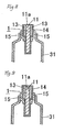
- this positive tab lead 1 is constituted such that a nickel partial coating layer 13 is formed on the entire externally exposed region (excluding the side edge portion 11a) of the aluminum plate 11 and a chitosan layer 13 containing chitosan is formed on the outermost surface.
- insulating tab films 15 and 15 made of polypropylene resin are thermally welded on both sides of the longitudinally intermediate region of the positive electrode tab lead 1 such that the insulating tab films cover the region where the partial coating layer 13 is formed.
- edge portion of the outer cover 31 is arranged such that the edge portion pinches the insulating tab films 15 and 15, and the edge portion of this outer cover 31 is sealed by, e.g., heat-sealing.
- No nickel coating layer is formed on the region of the aluminum plate 11 to be arranged in the outer cover 31.
- a nickel partial coating layer 13 is formed on the entire externally exposed region (including the side end face 11a) of the aluminum plate 11 of the positive tab lead 1.
- the other structure is the same as the structure shown in Fig. 8 .
- a method of forming the partial coating layers 13 and 23 although not specifically limited, a clad rolling method, an immersion plating method, an electroplating method, an evaporation method, a CVD (chemical vapor deposition) method, and a PVD (physical vapor deposition) method, can be exemplified. Among other things, it is preferable to use an immersion plating method or an electroplating method from a viewpoint of productivity and cost.
- the thickness of the partial coating layer 13 and 23 is preferably set to 1 to 10 ⁇ m.
- a method of forming the nickel coating layer 22 although not specifically limited, a clad rolling method, an immersion plating method, an electroplating method, an evaporation method, a CVD (chemical vapor deposition) method, and a PVD (physical vapor deposition) method, can be exemplified. Among other things, it is preferable to use an immersion plating method or an electroplating method from a viewpoint of productivity and cost.
- the thickness of the nickel coating layer 22 is preferably set to 1 to 10 ⁇ m.
- the surface roughness Ra of the aluminum plate 11 is preferably set so as to fall within the range of 0.03 to 0.5 ⁇ m. Setting the surface roughness within this range can improve the adhesiveness between the positive tab lead 1 and the insulating tab film 15.
- the surface roughness falling within this range can be formed by, for example, an emboss rolling method, a hair-line processing method, a shot blasting method, or a chemical etching method.
- the surface roughness Ra of the nickel coating layer 22 formed on the copper plate 21 is preferably set so as to fall within the range of 0.03 to 0.5 ⁇ m. Setting the surface roughness within this range can improve the adhesiveness between the negative tab lead 2 and the insulating tab film 25.
- the surface roughness falling within this range can be formed by, for example, an emboss rolling method, a hair-line processing method, a shot blasting method, or a chemical etching method.
- the surface roughness Ra is a value measured in accordance with JIS B0601-2001.
- the thickness of the aluminum plate 11 is preferably set to 0.1 to 1 mm, and the thickness of the copper plate 21 is preferably set to 0.1 to 1 mm.
- chitosan forming the chitosan layer 14 and 24 one or more compounds selected from the group consisting chitosan and chitosan derivatives is used.
- chitosan derivatives although not specifically limited, for example, carboxymethylchitosan, cationized chitosan, hydroxyalkylchitosan, glycerylchitosan, and salt of chitosan acid, can be exemplified.
- a method of forming the chitosan layer 14, 24 although not specifically limited, a method in which processing liquid containing chitosan is applied to the surface by a coating method, such as, e.g., a dipping method, a roll coating method, or a gravure coating method and dried can be exemplified. It is preferable that the solid content application quantity of the chitosan layer 14, 24 is set to 0.1 to 50 mg/m 2 .
- the positive electrode 33 although not specifically limited, any positive electrode material known for use in a nonaqueous electrolyte battery can be exemplified.
- a positive electrode formed by applying a mixed composition in which lithium salt (LiCoO 2 , LiNiO 2 , LiMnO 2 , LiFeO 2 ) as a positive electrode active material, a carbon powder as a conductive agent, and PVDF as a binding agent, are mixed, on the surface of the aluminum plate as a positive electrode collector and drying it can be exemplified.
- the carbon powder although not specifically limited, for example, powder graphite, granular graphite, fullerene graphite, and carbon nano-tube, can be exemplified.
- the negative electrode 34 although not specifically limited, for example, any negative electrode material known for use in a nonaqueous electrolyte battery can be used. Specifically, for example, a negative electrode formed by applying a mixed composition in which a carbon powder as a negative electrode active agent, and PVDF as a binding agent are mixed on the surface of the copper plate as a negative electrode collector and drying it can be exemplified.
- any nonaqueous electrolyte known for use in a nonaqueous electrolyte battery can be used.
- this nonaqueous electrolyte a gel nonaqueous electrolyte containing nonaqueous solvent and electrolyte is preferably used.
- the nonaqueous solvent although not specifically limited, for example, ethylene carbonate and propylene carbonate can be exemplified.
- the electrolyte although not specifically limited, for example, LiPF 6 , and LiClO 4 can be exemplified.
- separator 36 although not specifically limited, any separators known for use in a nonaqueous electrolyte battery can be exemplified. Concretely, porous polypropylene can be exemplified.
- an outer cover which is a laminate member in which a polymer film of, e.g., polyethylene, polypropylene, polyester or polyamide is arranged on the surface of a metal foil of, e.g., aluminum can be exemplified.
- an insulating film made of polyethylene or polypropylene can be exemplified.
- a positive tab lead 1 was obtained by forming a nickel partial coating layer (partial plated layer) 13 having a thickness of 3 ⁇ m on each of both sides of the tip end portion of an aluminum plate 11 which was 0.1 ⁇ m in surface roughness Ra and 500 ⁇ m in thickness by an electroplating method.
- a negative tab lead 2 was obtained by forming a nickel plated coating layer 22 having a thickness of 3 ⁇ m on the entire surface of a copper plate 21 which was 0.1 ⁇ m in surface roughness Ra and 500 ⁇ m in thickness by an electroplating method.
- the partial coating layer 13 of the positive tab lead and the nickel plated coating layer 22 were connected by soldering.
- the electric energy required for the soldering was 0.1 kWs.
- a positive tab lead 1 was obtained by forming a tin partial coating layer (partial plated layer) 13 having a thickness of 3 ⁇ m on each of both sides of the tip end portion of an aluminum plate 11 which was 0.1 ⁇ m in surface roughness Ra and 500 ⁇ m in thickness by an electroplating method.
- a negative tab lead 2 was obtained by forming a nickel plated coating layer 22 having a thickness of 3 ⁇ m on the entire surface of a copper plate 21 which was 0.1 ⁇ m in surface roughness Ra and 500 ⁇ m in thickness by an electroplating method and further forming a tin partial coating layer (partial plated layer) 23 having a thickness of 3 ⁇ m on both sides of the tip end portion of the nickel plated coating layer 22 by an electroplating method.
- the tin partial coating layer 13 of the positive tab lead and the tin partial coating layer 23 of the negative tab lead 2 were connected by soldering.
- the electric energy required for the soldering was 0.1 kWs.
- a positive tab lead 1 was obtained by forming a solder partial coating layer (partial plated layer) 13 having a thickness of 3 ⁇ m on each of both sides of the tip end portion of an aluminum plate 11 which was 0.1 ⁇ m in surface roughness Ra and 500 ⁇ m in thickness by an electroplating method.
- a negative tab lead 2 was obtained by forming a nickel plated coating layer 22 having a thickness of 3 ⁇ m on the entire surface of a copper plate 21 which was 0.1 ⁇ m in surface roughness Ra and 500 ⁇ m in thickness by an electroplating method and further forming a solder coating layer (partial plated layer) 23 having a thickness of 3 ⁇ m on both sides of a tip end portion of the nickel plated coating layer 22.
- solder partial coating layer 13 of the positive tab lead and the solder partial coating layer 23 of the negative tab lead 2 were connected by soldering.
- the electric energy required for the soldering was 0.1 kWs.
- a positive tab lead of an aluminum plate which was 0.1 ⁇ m in surface roughness Ra and 500 ⁇ m in thickness was prepared, and a negative tab lead was obtained by forming a nickel plated coating layer having a thickness of 3 ⁇ m on the entire surface of a copper plate which was 0.1 ⁇ m in surface roughness Ra and 500 ⁇ m in thickness by an electroplating method.
- the positive tab lead and the nickel plated coating layer of the negative tab lead were connected by a welding method.
- the electric energy required for the welding was 10 kWs.
- connection strength was measured by subjecting the mutually connected positive tab lead and negative tab lead to a tensile test.
- the connection strength of 60 MPa or more was denoted as “ O ,” and the connection strength less than 60 MP was denoted as " ⁇ .”
- Example 1 Aluminum plate Copper plate / Ni plating Welding 10 ⁇
- Example 1 Aluminum plate / Ni partial plating Copper plate / Ni plating Soldering 0.1 ⁇
- Example 2 Aluminum plate / Sn partial plating Copper plate / Ni plating / Sn partial plating Soldering 0.1 ⁇
- Example 3 Aluminum plate / solder partial plating Copper plate / Ni plating / Solder partial plating Soldering 0.1 ⁇
- a positive tab lead 1 was obtained by forming a nickel partial coating layer (partial plated layer) 13 having a thickness of 3 ⁇ m on both sides of the tip end portion of an aluminum plate 11 which was 0.03 ⁇ m in surface roughness Ra and 500 ⁇ m in thickness by an electroplating method and further forming a chitosan layer 14 which was 50 mg/m 2 in solid content adhered quantity by applying carboxymethyl chitosan aqueous solution (concentration: 0.5 mass%) on the entire surface of the aluminum plate and the nickel partial coating layer and then drying it (see Fig. 3 ).
- a positive tab lead 1 was obtained in the same manner as in Example 4 except that the solid content adhered quantity of the chitosan layer 14 was set to 0.5 mg/m 2 (see Fig. 3 ).
- a positive tab lead 1 was obtained in the same manner as in Example 4 except that an aluminum plate 11 having a surface roughness Ra of 0.1 ⁇ m and the solid content adhered quantity of the chitosan layer 14 was set to 1.0 mg/m 2 (see Fig. 3 ).
- a positive tab lead 1 was obtained by forming a tin plated coating layer (partial plated layer) 13 having a thickness of 3 ⁇ m on both sides of the tip end portion of an aluminum plate 11 which was 0.1 ⁇ m in surface roughness Ra and 500 ⁇ m in thickness by an electroplating method and further forming a chitosan layer 14 which was 1.0 mg/m 2 in solid content adhered quantity by applying carboxymethyl chitosan aqueous solution (concentration: 0.5 mass%) on the entire surface of the aluminum plate and the tin partial coating layer and then drying it (see Fig. 3 ).
- a positive tab lead 1 was obtained by forming a solder partial coating layer (partial plated layer) 13 having a thickness of 3 ⁇ m on both sides of the tip end portion of an aluminum plate 11 which was 0.1 ⁇ m in surface roughness Ra and 500 ⁇ m in thickness by an electroplating method and further forming a chitosan layer 14 which was 1.0 mg/m 2 in solid content adhered quantity by applying carboxymethyl chitosan aqueous solution (concentration: 0.5 mass%) on the entire surface of the aluminum plate and the solder partial coating layer and then drying it (see Fig. 3 ).
- a positive tab lead made of an aluminum plate which was 0.03 ⁇ m in surface roughness Ra and 500 ⁇ m in thickness was prepared.
- Leakage of the liquid (electrolytic solution) from the positive tab portion of the battery having the positive tab lead obtained as mentioned above was evaluated in accordance with the following evaluation method.
- insulating tab films 15 and 15 made of polypropylene resin were thermally welded on both sides of the longitudinally intermediate region of the positive tab lead 1, and the edge portion of an outer cover 31 having a non-stretched polypropylene layer on the inner surface side was sealed by heat sealing in such a manner that the edge portion pinched the insulating tab films 15 and 15.
- electrolyte solution LiPF 6 having a concentration of 1M
- This sample piece was subjected to a durability test in an oven of 85 °C for 30 days. 1,000 samples were prepared every Example, and subjected to a durability test. The number of samples which caused leakage of electrolytic solution from the positive tab portion (i.e., the number of samples which caused defects) was counted.
- Example 2 Positive tab lead Evaluation of leakage Structure Surface roughness chitosan content of aluminum Ra ( ⁇ m) solid application plate quantity (mg/m 2 ) (number of samples caused leak defective among 1,000 samples) Comp.
- Example 2 Aluminum plate 0.03 0 52
- Example 4 Aluminum plate / Ni partial plating / chitosan layer 0.03 50 0
- Example 5 Aluminum plate / Ni partial plating / chitosan layer 0.03 0.5 1
- Example 6 Aluminum plate / Ni partial plating / chitosan layer 0.1 1.0 0
- Example 7 Aluminum plate / Sn partial plating / chitosan layer 0.1 1.0 0
- Example 8 Aluminum plate / Solder partial plating / chitosan layer 0.1 1.0 0
- a negative tab lead 2 was obtained by forming a nickel coating layer 22 which was 0.1 ⁇ m in surface roughness Ra and 3 ⁇ m in thickness on the entire surface of the copper plate 21 having a thickness of 500 ⁇ m.
- a negative tab lead 2 was obtained by forming a nickel coating layer 22 which was 0.02 ⁇ m in surface roughness Ra and 3 ⁇ m in thickness on the entire surface of a copper plate 21 having a thickness of 500 ⁇ m by an electroplating method, and further forming a chitosan layer 24 which was 1.0 mg/m 2 in solid content adhered quantity by applying carboxymethyl chitosan aqueous solution (concentration: 0.5 mass%) on the outer surface of the nickel coating layer 22 and then drying it (see Fig. 5 ).
- a negative tab lead 2 was obtained in the same manner as in Example 10 except that a nickel coating layer 22 having a surface roughness Ra of 0.1 ⁇ m was formed (see Fig. 5 ).
- a negative tab lead 2 was obtained by forming a nickel coating layer 22 which was 0.1 ⁇ m in surface roughness Ra and 3 ⁇ m in thickness on the entire surface of a copper plate 21 having a thickness of 500 ⁇ m by an electroplating method, forming a tin partial coating layer (partial plated layer) 23 having a thickness of 3 ⁇ m on both sides of the tip portion of the nickel plated coating layer 22 by an electroplating method, and further forming a chitosan layer 24 which was 1.0 mg/m 2 in solid content adhered quantity by applying carboxymethyl chitosan aqueous solution (concentration: 0.5 mass%) on the entire surface of the nickel coating layer and the partial plated layer and then drying it (see Fig. 7 ).
- a negative tab lead 2 was obtained by forming a nickel coating layer 22 which was 0.1 ⁇ m in surface roughness Ra and 3 ⁇ m in thickness on the entire surface of a copper plate 21 having a thickness of 500 ⁇ m by an electroplating method, forming a solder partial coating layer (partial plated layer) 23 having a thickness of 3 ⁇ m on both sides of the tip portion of the nickel coating layer 22 by an electroplating method, and further forming a chitosan layer 24 which was 1.0 mg/m 2 in solid content adhered quantity by applying carboxymethyl chitosan aqueous solution (concentration: 0.5 mass%) on the entire surface of the nickel coating layer and the solder partial coating layer and then drying it (see Fig. 7 ).
- insulating tab films 25 and 25 made of polypropylene resin were thermally welded on both sides of the longitudinally intermediate region of the negative tab lead 2, and the edge portion of an outer cover 31 having a non-stretched polypropylene layer on the inner surface side was sealed by heat sealing in such a manner that the edge portion pinched the insulating tab films 25 and 25.
- electrolyte solution LiPF 6 having a concentration of 1M
- This product was subjected to a durability test in an oven of 85 °C for 30 days. 1,000 samples were prepared every Example, and subjected to a durability test. The number of samples which caused leakage of electrolytic solution from the negative tab portion (i.e., the number of samples which caused defects) was counted.
- a positive tab lead 1 was obtained by forming a nickel partial coating layer (partial plated layer) 13 having a thickness of 3 ⁇ m on both sides of the tip end portion of an aluminum plate 11 which was 0.1 ⁇ m in surface roughness Ra and 500 ⁇ m in thickness by an electroplating method and further forming a chitosan layer 14 which was 50 mg/m 2 in solid content adhered quantity by applying carboxymethyl chitosan aqueous solution (concentration: 0.5 mass%) on the entire surface of the aluminum plate and the partial coating layer and then drying it (see Fig. 8 ).
- insulating tab films 15 and 15 were thermally welded to both sides of the longitudinally intermediate region of the positive tab lead 1 in such a manner that the insulating tab films cover the region where the partial coating layer 13 was formed (see Fig. 8 ). That is, a positive tab lead 1 in which a nickel partial coating layer (partial plated layer) 13 was on the entire region (excluding the side edge face 11a) of the aluminum plate 11 to be disposed to an outside of the outer cover 31 was obtained (see Fig. 8 ).
- the edge portion of the outer cover 31 having a non-stretched polypropylene layer on the inner surface side was sealed by heat sealing in such a manner that the edge portion pinched the insulating tab films 15 and 15.
- electrolyte solution LiPF 6 having a concentration of 1M
- This sample was subjected to a durability test in an oven of 85 °C for 30 days. 1,000 samples were prepared every Example, and subjected to a durability test. The number of samples which caused leakage of electrolytic solution from the negative tab portion (i.e., the number of samples which caused defects) was counted.
- a positive tab lead 1 was obtained by forming a nickel partial coating layer (partial plated layer) 13 having a thickness of 3 ⁇ m on both sides (both surfaces) of the tip end portion of an aluminum plate 11 which was 0.1 ⁇ m in surface roughness Ra and 500 ⁇ m in thickness by an electroplating method and further forming a chitosan layer 14 which was 50 mg/m 2 in solid content adhered quantity by applying carboxymethyl chitosan aqueous solution (concentration: 0.5 mass%) on the entire surface of the aluminum plate and the partial coating layer and then drying it (see Fig. 8 ).
- insulating tab films 15 and 15 of polypropylene resin were thermally welded to both sides of the longitudinally intermediate region of the positive tab lead 1 in such a manner that the insulating tab films cover the region where the partial coating layer 13 was formed (see Fig. 8 ). That is, a positive tab lead 1 in which a nickel partial coating layer (partial plated layer) 13 was on the entire region (excluding the side edge face) of the aluminum plate 11 to be disposed to an outside of the outer cover was obtained (see Fig. 8 ).
- a negative tab lead 2 was obtained by forming a nickel plated coating layer 22 having a thickness of 3 ⁇ m on the entire surface of a copper plate 21 which was 0.1 ⁇ m in the surface roughness Ra and 500 ⁇ m in thickness, and further forming a chitosan layer 24 which was 50 mg/m 2 in solid content adhered quantity by applying carboxymethyl chitosan aqueous solution (concentration: 0.5 mass%) on the outer surface of the nickel coating layer 22 and then drying it (see Fig. 5 ).
- the partial coating layer 13 of the positive tab lead and the nickel plated coating layer 22 were connected by soldering.
- the electric energy required for the soldering was 0.1 kWs.
- a positive tab lead 1 was obtained by forming a nickel partial coating layer (partial plated layer) 13 having a thickness of 3 ⁇ m on both sides of the tip end portion of an aluminum plate 11 by an electroplating method and further forming a chitosan layer 14 which was 50 mg/m 2 in solid content adhered quantity by applying carboxymethyl chitosan aqueous solution (concentration: 0.5 mass%) on the entire surface of the aluminum plate and the nickel partial coating layer and then drying it (see Fig. 3 ).
- a negative tab lead 2 was obtained by forming a nickel plated coating layer 22 having a thickness of 3 ⁇ m on the entire surface of a copper plate 21 which was 0.1 ⁇ m in surface roughness Ra and 500 ⁇ m in thickness by an electroplating method, and further forming a chitosan layer 24 which was 50 mg/m 2 in solid content adhered quantity by applying carboxymethyl chitosan aqueous solution (concentration: 0.5 mass%) on the entire surface of the nickel coating layer and then drying it (see Fig. 5 ).
- the partial coating layer 13 of the positive tab lead and the nickel plated coating layer 22 of the negative tab lead 2 were connected by soldering.
- the electric energy required for the soldering was 0.1 kWs.
- a positive tab lead 1 was obtained by forming a tin plated coating layer (partial plated layer) 13 having a thickness of 3 ⁇ m on both sides of the tip end portion of an aluminum plate 11 which was 0.1 ⁇ m in surface roughness Ra and 500 ⁇ m in thickness by an electroplating method and further forming a chitosan layer 14 which was 50 mg/m 2 in solid content adhered quantity by applying carboxymethyl chitosan aqueous solution (concentration: 0.5 mass%) on the entire surface of the aluminum plate and the tin partial coating layer and then drying it (see Fig. 3 ).
- a negative tab lead 2 was obtained by forming a nickel plated coating layer 22 which having a thickness of 3 ⁇ m on the entire surface of a copper plate 21 which was 0.1 ⁇ m in surface roughness Ra and 500 ⁇ m in thickness by an electroplating method, forming a tin partial coating layer (partial plated layer) 23 having a thickness of 3 ⁇ m on both sides of the tip portion of the nickel plated coating layer 22 by an electroplating method, and further forming a chitosan layer 24 which was 50 mg/m 2 in solid content adhered quantity by applying carboxymethyl chitosan aqueous solution (concentration: 0.5 mass%) on the entire surface of the nickel coating layer and the tin partial coating layer and then drying it (see Fig. 7 ).
- the tin partial coating layer 13 of the positive tab lead and the tin partial coating layer 23 were connected by soldering.
- the electric energy required for the soldering was 0.1 kWs.
- a positive tab lead 1 was obtained by forming a solder partial coating layer (partial plated layer) 13 having a thickness of 3 ⁇ m on both sides of the tip end portion of an aluminum plate 11 which was 0.1 ⁇ m in surface roughness Ra and 500 ⁇ m in thickness by an electroplating method and further forming a chitosan layer 14 which was 50 mg/m 2 in solid content adhered quantity by applying carboxymethyl chitosan aqueous solution (concentration: 0.5 mass%) on the entire surface of the aluminum plate and the solder partial coating layer and then drying it (see Fig. 3 ).
- a negative tab lead 2 was obtained by forming a nickel plated coating layer 22 having a thickness of 3 ⁇ m on the entire surface of a copper plate 21 which was 0.1 ⁇ m in surface roughness Ra and 500 ⁇ m in thickness by an electroplating method, forming a solder partial coating layer (partial plated layer) 23 having a thickness of 3 ⁇ m on both sides of the tip portion of the nickel plated coating layer 22 by an electroplating method, and further forming a chitosan layer 24 which was 50 mg/m 2 in solid content adhered quantity by applying carboxymethyl chitosan aqueous solution (concentration: 0.5 mass%) on the entire surface of the nickel coating layer and the solder partial coating layer and then drying it (see Fig. 7 ).
- solder partial coating layer 13 of the positive tab lead and the solder partial coating layer 23 of the negative tab lead 2 were connected by soldering.
- the electric energy required for the soldering was 0.1 kWs.
- connection strength between the positive tab lead and the negative tab lead connected with each other as mentioned above in Examples 15 to 18 was evaluated in accordance with the aforementioned connection strength evaluation method, and the corrosion resistance of the positive tab lead and the negative tab lead connected with each other as mentioned above in Examples 15 to 18 and Comparative Example 1 was evaluated in accordance with the following evaluation method.
- the positive tab lead and the negative tab lead connected with each other were set in a salt spray testing device (Temperature: 35 °C) and the device was operated for 500 hours in this state. Thereafter, the positive tab lead and the negative tab lead were taken out and visually inspected in degree of corrosion. The corrosion was evaluated in accordance with the following criterion.
- the surface roughness Ra of the aluminum plate and the surface roughness Ra of the nickel coating layer (plated layer) formed on the copper plate were adjusted by applying an embossing rolling method to each plate.
- the positive tab lead and negative tab lead can be preferably applied to, for example, a tab lead for a secondary battery such as a lithium secondary battery or a tab lead for a capacitor.
Landscapes
- Chemical & Material Sciences (AREA)
- Chemical Kinetics & Catalysis (AREA)
- Electrochemistry (AREA)
- General Chemical & Material Sciences (AREA)
- Engineering & Computer Science (AREA)
- Manufacturing & Machinery (AREA)
- Connection Of Batteries Or Terminals (AREA)
- Sealing Battery Cases Or Jackets (AREA)
Abstract
Description
- The present invention relates to a positive tab lead and a negative tab lead preferably used as a tab lead for, e.g., a secondary battery, such as, e.g., a lithium battery, or a tab lead for, e.g., a capacitor.
- In this specification and claims, the language of "aluminum" is used to mean to include aluminum and its alloys, and the language of "copper" is used to mean to include copper and its alloys. Furthermore, in this specification and claims, the language of "battery" is used to mean to include not only a battery, such as, e.g., a secondary battery but also a capacitor.
- A secondary battery (e.g., a nonaqueous electrolyte lithium secondary battery) or a capacitor is provided with a tab lead for taking out electricity. Conventionally, an aluminum plate was used as a positive tab lead, and a copper plate was used as a negative tab lead (see Patent Document 1).
- In the case of using such a battery as a power source for, e.g., an automobile, it is required to take out a large current, and therefore a plurality of unit cells are electrically connected to constitute an assembled battery. In other words, the electrode terminals (tab leads) of a plurality of unit cells are connected to constitute an assembled battery. In many cases, conventionally, such a tab lead connection was performed by welding.
-
- [Patent Document 1] Japanese Unexamined Laid-open Patent Publication No.
2008-27771 JP-2008-27771, A - In cases where tab leads are connected by welding as in the aforementioned prior art, there was a problem that a sufficient connection strength could not be obtained. Furthermore, in the case of connecting them by welding, there was a problem that the energy cost was high.
- The present invention was made in view of the aforementioned technical background, and aims to provide a positive electrode, a negative electrode, and a battery capable of connecting tab leads with each other with a sufficient connection strength at lower energy cost.
- In order to attain the aforementioned objects, the present invention provides the following means.
- [1] A positive tab lead characterized in that a partial coating layer made of nickel, tin or solder is formed on at least a part of a region of an aluminum plate to be exposed to an outside of an outer cover.
- [2] The positive tab lead as recited in the
aforementioned Item 1, wherein a surface roughness Ra of the aluminum plate is 0.03 to 0.5 µm. - [3] The positive tab lead as recited in the
aforementioned Item 1, wherein a surface roughness Ra of a region of the aluminum plate where the partial coating layer is not formed is 0.03 to 0.5 µm. - [4] The positive tab lead as recited in any one of the
aforementioned Items 1 to 3, wherein the partial coating layer is formed on an entire region of the aluminum plate to be exposed to the outside of the outer cover. - [5] The positive tab lead as recited in any one of the
aforementioned Items 1 to 4, wherein a chitosan layer containing one or more compounds selected from a group consisting of chitosan and chitosan derivatives is further formed on a surface of the partial coating layer and the aluminum plate. - [6] A negative tab lead characterized in that a nickel coating layer is formed on an entire surface of a copper plate.
- [7] A negative tab lead characterized in that a nickel coating layer is formed on an entire surface of a copper plate, and a partial coating layer made of tin or solder is formed on at least a part of a region of an outer surface of the nickel coating layer to be exposed to an outside of an outer cover.
- [8] The negative tab lead as recited in the aforementioned Item 6 or 7, wherein a surface roughness Ra of the nickel coating layer is 0.03 to 0.5 µm.
- [9] The negative tab lead as recited in any one of the aforementioned Items 6 to 8, wherein a chitosan layer containing one or more compounds selected from a group consisting of chitosan and chitosan derivatives is further formed on a surface of the nickel coating layer and/or the partial coating layer.
- [10] A battery comprising a battery main body including a positive electrode, a negative electrode, and electrolyte, an outer cover enclosing the battery main body therein, a positive tab lead electrically connected to the positive electrode, and a negative tab lead electrically connected to the negative electrode, wherein a part of the positive tab lead is exposed to an outside of the outer cover, and a part of the negative tab lead is exposed to the outside, characterized in that
the positive tab lead includes an aluminum plate and a partial coating layer made of nickel, tin or solder formed on at least a part of a region of the aluminum plate exposed to the outside, and
the negative tab lead includes a copper plate and a nickel coating layer formed on an entire surface of the copper plate. - [11] A battery comprising a battery main body including a positive electrode, a negative electrode, and electrolyte, an outer cover enclosing the battery main body therein, a positive tab lead electrically connected to the positive electrode, and a negative tab lead electrically connected to the negative electrode, wherein a part of the positive tab lead is exposed to an outside of the outer cover, and a part of the negative tab lead is exposed to the outside, characterized in that
the positive tab lead includes an aluminum plate and a partial coating layer made of nickel formed on at least a part of a region of the aluminum plate exposed to the outside, and
the negative tab lead includes a copper plate and a nickel coating layer formed on an entire surface of the copper plate. - [12] A battery comprising a battery main body including a positive electrode, a negative electrode, and electrolyte, an outer cover enclosing the battery main body therein, a positive tab lead electrically connected to the positive electrode, and a negative tab lead electrically connected to the negative electrode, wherein a part of the positive tab lead is exposed to an outside of the outer cover, and a part of the negative tab lead is exposed to the outside, characterized in that
the positive tab lead includes an aluminum plate and a partial coating layer made of tin formed on at least a part of a region of the aluminum plate exposed to the outside, and
the negative tab lead includes a copper plate, a nickel coating layer formed on an entire surface of the copper plate, and a partial coating layer made of tin formed on at least a part of an region of the nickel coating layer exposed to the outside. - [13] A battery comprising a battery main body including a positive electrode, a negative electrode, and electrolyte, an outer cover enclosing the battery main body therein, a positive tab lead electrically connected to the positive electrode, and a negative tab lead electrically connected to the negative electrode, wherein a part of the positive tab lead is exposed to an outside of the outer cover, and a part of the negative tab lead is exposed to the outside, characterized in that
the positive tab lead includes an aluminum plate and a partial coating layer made of solder formed on at least a part of a region of the aluminum plate exposed to the outside, and
the negative tab lead includes a copper plate, a nickel coating layer formed on an entire surface of the copper plate, and a partial coating layer made of solder formed on at least a part of a region of the nickel coating layer exposed to the outside. - [14] The battery as recited in any one of the aforementioned Items 10 to 13, wherein the partial coating layer is formed on an entire region of the aluminum plate of the positive electrode exposed to the outside.
- According to the invention [1] (positive tab lead), a partial coating layer made of nickel, tin or solder is formed on at least a part of a region of an aluminum plate to be exposed to an outside of an outer cover. Therefore, it is possible to connect tab leads with each other by soldering. Furthermore, since tab leads can be connected by soldering, the energy cost for the connection can be kept low, which is economically beneficial.
- According to the invention [2], since a surface roughness Ra of the aluminum plate is set to 0.03 to 0.5 µm, the adhesiveness between the positive tab lead and an insulating tab film can be increased, which can improve the battery endurance reliability.
- According to the invention [3], since a surface roughness Ra of a region of the aluminum plate where the partial coating layer is not formed is set to 0.03 to 0.5 µm, the adhesiveness between the positive tab lead and an insulating tab film can be increased, which can improve the battery endurance reliability.
- According to the invention [4], since the partial coating layer is formed on an entire region (excluding the side edge face) of the aluminum plate to be exposed to the outside of the outer cover, the corrosion resistance of the externally exposed region can be enhanced, which in turn can further improve the battery endurance reliability. It should be noted that the
side edge face 11a of the region of the aluminum plate to be exposed to the outside of the outer cover can be covered by the partial coating layer 13 (seeFig. 9 ) but is not always required to be covered by the partial coating layer 13 (seeFig. 8 ). The invention [4] covers both of these structures. - According to the invention [5], since a chitosan layer containing one or more compounds selected from a group consisting of chitosan and chitosan derivatives is further formed on a surface of the partial coating layer and the aluminum plate, the adhesiveness between the positive tab lead and an insulating tab film can be further improved, which in turn can further improve the battery endurance reliability.
- According to the invention [6] (negative tab lead), since a nickel coating layer is formed on an entire surface (excluding the side edge face) of a copper plate, tab leads can be connected with each other by soldering with a sufficient connection strength. Furthermore, the connection of tab leads can be performed by soldering, reducing the energy cost for the connection, which is economically beneficial. It should be noted that the side edge face of the copper plate can be covered by the
nickel coating layer 22 but is not always required to be covered by the nickel coating layer 22 (seeFig. 5 ). The invention [6] covers both of these structures. - According to the invention [7] (negative tab lead), since a nickel coating layer is formed on an entire surface of a copper plate and a partial coating layer made of tin or solder is formed on at least a part of a region of an outer surface of the nickel coating layer to be exposed to an outside of an outer cover, tab leads can be connected with each other by soldering with a sufficient connection strength. Furthermore, the connection of tab leads can be performed by soldering, reducing the energy cost for the connection, which is economically beneficial. It should be noted that the side edge face of the copper plate can be covered by the
nickel coating layer 22 but is not always required to be covered by the nickel coating layer 22 (seeFig. 7 ). The invention [7] covers both of these structures. - According to the invention [8], since a surface roughness Ra of the nickel coating layer is set to 0.03 to 0.5 µm, the adhesiveness between the negative tab lead and an insulating tab film can be improved, which in turn can improve the battery endurance reliability.
- According to the invention [9], since a chitosan layer containing one or more compounds selected from a group consisting of chitosan and chitosan derivatives is further formed on the nickel coating layer and/or the partial coating layer, the adhesiveness between the negative tab lead and an insulating tab film can be further improved, which in turn can further improve the battery endurance reliability.
- According to the invention [10], it is constituted that the positive tab lead includes an aluminum plate and a partial coating layer made of nickel, tin or solder formed on at least a part of a region of the aluminum plate exposed to the outside and the negative tab lead includes a copper plate and a nickel coating layer formed on an entire surface (excluding the side edge face) of the copper plate. Therefore, in the case of forming an assembled battery by electrically connecting battery cells structured mentioned above, for example, the partial coating layer of the positive tab lead of a battery cell and the nickel coating layer of the negative tab lead of another battery cell can be connected with a sufficient connecting strength by soldering. Furthermore, since tab leads can be connected with each other by soldering, the energy cost for the connection can be kept low, which is economically beneficial. It should be noted that the side edge face of the copper plate can be covered by the nickel coating layer 22 (see
Fig. 5 ) but is not always required to be covered by thenickel coating layer 22. The invention [10] covers both of these structures. - According to the invention [11], it is constituted such that the the positive tab lead includes an aluminum plate and a partial coating layer made of tin formed on at least a part of a region of the aluminum plate exposed to the outside, and the negative tab lead includes a copper plate, a nickel coating layer formed on an entire surface (excluding the side edge face) of the copper plate, and a partial coating layer made of tin formed on at least a part of a region of the nickel coating layer exposed to the outside. Therefore, in the case of forming an assembled battery by electrically connecting battery cells structured mentioned above, for example, the partial coating layer of the positive tab lead of a battery cell and the nickel coating layer of the negative tab lead of another battery cell can be connected with a sufficient connection strength by soldering. Furthermore, since tab leads can be connected with each other by soldering, the energy cost for the connection can be kept low, which is economically beneficial. In this structure [11], since the partial coating layer of the positive tab lead and the nickel coating layer of the negative tab lead are made of the same kind of metal (nickel), there is an advantage that the cost for forming these layers can be reduced. It should be noted that the side edge face of the copper plate can be covered by the nickel coating layer 22 (see
Fig. 7 ) but is not always required to be covered by thenickel coating layer 22. The invention [11] covers both of these structures. - According to the invention [12], it is constituted such that the positive tab lead includes an aluminum plate and a partial coating layer made of nickel formed on at least a part of a region of the aluminum plate exposed to the outside, and the negative tab lead includes a copper plate and a nickel coating layer formed on an entire surface (excluding the side edge face) of the copper plate. Therefore, in the case of forming an assembled battery by electrically connecting battery cells structured mentioned above, for example, the partial coating layer of the positive tab lead of a battery cell and the partial coating layer of the negative tab lead of another battery cell can be connected with a sufficient connection strength by soldering. Furthermore, since tab leads can be connected with each other by soldering, the energy cost for the connection can be kept low, which is economically beneficial. It should be noted that the side edge face of the copper plate can be covered by the nickel coating layer 22 (see
Fig. 7 ) but is not always required to be covered by thenickel coating layer 22. The invention [12] covers both of these structures. - According to the invention [13], it is constituted such that the positive tab lead includes an aluminum plate and a partial coating layer made of solder formed on at least a part of a region of the aluminum plate exposed to the outside and the negative tab lead includes a copper plate, a nickel coating layer formed on an entire surface (excluding the side edge face) of the copper plate, and a partial coating layer made of solder formed on at least a part of a region of the nickel coating layer exposed to the outside. Therefore, in the case of forming an assembled battery by electrically connecting battery cells structured mentioned above, for example, the partial coating layer of the positive tab lead of a battery cell and the partial coating layer of the negative tab lead of another battery cell can be connected with a sufficient connection strength by soldering. Furthermore, since tab leads can be connected with each other by soldering, the energy cost for the connection can be kept low, which is economically beneficial. It should be noted that the side edge face of the copper plate can be covered by the nickel coating layer 22 (see
Fig. 7 ) but is not always required to be covered by thenickel coating layer 22. The invention [13] covers both of these structures. - According to the invention [14], since the partial coating layer is formed on an entire region (excluding the side edge face) of the aluminum plate of the positive electrode exposed to the outside, the corrosion resistance of the externally exposed region can be enhanced, which in turn can further improve the battery endurance reliability. It should be noted that the
side edge face 11a of the region of the aluminum plate to be exposed to the outside of the outer cover can be covered by the partial coating layer 13 (seeFig. 9 ) but is not always required to be covered by the partial coating layer 13 (seeFig. 8 ). The invention [14] covers both of these structures. -
- [
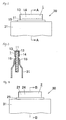
Fig. 1] Fig. 1(a) is a perspective view showing an embodiment of a battery of the present invention, andFig. 1(b) is an enlarged cross-sectional view taken along the line X-X inFig. 1(a) . - [
Fig. 2] Fig. 2 is a plan view showing a positive tab lead and its vicinity of the battery according to the embodiment of the present invention. - [
Fig. 3] Fig. 3 is a cross-sectional view taken along the line A-A inFig. 2 . - [
Fig. 4] Fig. 4 is a plan view showing a negative tab lead and its vicinity of the battery according to the embodiment of the present invention. - [
Fig. 5] Fig. 5 is a cross-sectional view taken along the line B-B inFig. 4 . - [
Fig. 6] Fig. 6 is a plan view showing a negative tab lead and its vicinity of a battery according to another embodiment of the present invention. - [
Fig. 7] Fig. 7 is a cross-sectional view taken along the line C-C inFig. 6 . - [
Fig. 8] Fig. 8 is a plan view showing a positive tab lead and its vicinity of a battery according to still another embodiment of the present invention. - [
Fig. 9] Fig. 9 is a plan view showing a positive tab lead and its vicinity of a battery according to still yet another embodiment of the present invention. -
Fig. 1 shows abattery 30 according to an embodiment of the present invention. Thebattery 30 of this first embodiment is a nonaqueous electrolyte lithium secondary battery. In thisbattery 30, a film-likepositive electrode 33 and a film-likenegative electrode 34 are arranged one on the other via aseparator 36 in a superimposed manner with anonaqueous electrolyte 35 interposed between the positive electrode and the negative electrode so that electric charge/discharge can be performed by transmission of lithium ions. The batterymain body 32 including thepositive electrode 33, thenegative electrode 34 and theelectrolyte 35 is covered by anouter cover 31 in a liquid-tight manner. That is, the battery main body is sealed in the outer cover 31 (seeFig. 1 ). - A
positive tab lead 1 is electrically connected to thepositive electrode 33, and a part of thepositive tab lead 1 is exposed (i.e., extended) to an outside of the outer cover 31 (seeFigs. 1 to 3 ). In this embodiment, as shown inFig. 3 , thepositive tab lead 1 is a member in which a nickelpartial coating layer 13 is formed on a part (tip end portion) of the externally exposed region of thealuminum plate 11 and achitosan layer 14 containing chitosan is formed on an outermost surface. No nickel coating layer is formed on the region of thealuminum plate 11 to be arranged in theouter cover 31. - As shown in
Fig. 3 , insulatingtab films positive tab lead 1, and the edge portion of theouter cover 31 is arranged such that the edge portion pinches the insulatingtab films outer cover 31 is sealed by, e.g., heat-sealing. - A
negative tab lead 2 is electrically connected to thenegative electrode 34, and a part of thenegative tab lead 2 is exposed (i.e., extended) to an outside of the outer cover 31 (seeFigs. 1 ,4 and5 ). In this embodiment, as shown inFig. 5 , thenegative tab lead 2 is a member in which anickel coating layer 22 is formed on an entire surface of thecopper plate 21 and achitosan layer 24 containing chitosan is formed on an entire outermost surface of thenickel coating layer 22. - As shown in
Fig. 5 , insulatingtab films negative tab lead 2, and the edge portion of theouter cover 31 is arranged such that the edge portion pinches the insulatingtab films outer cover 31 is sealed by, e.g., heat-sealing. - In forming an assembled battery by electrically connecting the batteries, or
unit cells 30, by soldering, for example, apartial coating layer 13 of apositive tab lead 1 of oneunit cell 30 and anickel coating layer 22 of anegative tab lead 2 of anotherunit cell 30, sufficient connection strength can be attained. - As a
battery cell 30 of the present invention, the following structure (second embodiment) can be employed. That is, it is acceptable to employ a structure that, in the battery of the aforementioned embodiment, as thepositive tab lead 1, a tinpartial coating layer 13 is formed on a part (tip end portion) of the externally exposed region of thealuminum plate 11 and achitosan layer 14 containing chitosan is formed on an outermost surface (seeFig. 3 ), while as thenegative tab lead 2, as shown inFigs. 6 and 7 , anickel coating layer 22 is formed on the entire surface of thecupper plate 21, a tinpartial coating layer 23 is formed on a part of the externally exposed region of thenickel coating layer 22, and achitosan layer 24 containing chitosan is formed on the outermost surface. No tin coating layer is formed on the region of thealuminum plate 11 to be arranged in theouter cover 31. - As shown in
Fig. 3 , insulatingtab films positive tab lead 1, and the edge portion of theouter cover 31 is arranged such that the edge portion pinches the insulatingtab films outer cover 31 is sealed by, e.g., heat-sealing. - As shown in
Fig. 7 , insulatingtab films negative tab lead 2, and the edge portion of theouter cover 31 is arranged such that the edge portion pinches the insulatingtab films outer cover 31 is sealed by, e.g., heat-sealing. - In the case of forming an assembled battery by electrically connecting batteries or
unit cells 30 of the aforementioned embodiment, for example, by soldering the tinpartial coating layer 13 of thepositive tab lead 1 of oneunit cell 30 and a tinpartial coating layer 23 of anegative tab lead 2 of anotherunit cell 30, sufficient connection strength can be attained. - As a
battery 30 of this invention, the following structure (third embodiment) can be employed. That is, it is acceptable to employ a structure that, in the battery of the aforementioned second embodiment, as thepositive tab lead 1, a solderpartial coating layer 13 is formed on a part (tip end portion) of the externally exposed region of thealuminum plate 11 and achitosan layer 14 containing chitosan is formed on an outermost surface (seeFig. 3 ), while as thenegative tab lead 2, as shown inFigs. 6 and 7 , anickel coating layer 22 is formed on the entire surface of thecupper plate 21, a solderpartial coating layer 23 is formed on a part of the externally exposed region of thenickel coating layer 22, and achitosan layer 24 containing chitosan is formed on the outermost surface. No solder coating layer is formed on the region of thealuminum plate 11 to be arranged in theouter cover 31. - As shown in
Fig. 3 , the insulatingtab films positive tab lead 1, and the edge portion of theouter cover 31 is arranged such that the edge portion pinches the insulatingtab films outer cover 31 is sealed by, e.g., heat-sealing. - As shown in
Fig. 7 , the insulatingtab films negative tab lead 2, and the edge portion of theouter cover 31 is arranged such that the edge portion pinches the insulatingtab films outer cover 31 is sealed by, e.g., heat-sealing. - In the case of forming an assembled battery by electrically connecting batteries, or
unit cells 30 of the aforementioned third embodiment, for example, by soldering the solderpartial coating layer 13 of thepositive tab lead 1 of onebattery 30 and a solderpartial coating layer 23 of anegative tab lead 2 of anotherbattery 30, sufficient connection strength can be attained. - In the aforementioned first to third embodiments, a structure that the
partial coating layer 13 is formed on a part of the region of thealuminum plate 11 to be exposed to an outside of theouter cover 31 is employed. The present invention is not limited to such structure, and allows to employ a structure that thepartial coating layer 13 is formed on the entire region (excluding theside edge face 11a) of thealuminum plate 11 to be exposed to an outside of theouter cover 31, and also allows to employ a structure that thepartial coating layer 13 is formed on the entire region (including theside edge face 11a) of thealuminum plate 11 to be exposed to an outside of theouter cover 31. Employment of such structure has an advantage that the corrosion resistance of the externally exposed region can be enhanced. - An example of the former modification is shown in
Fig. 8 . In this embodiment, as shown inFig. 8 , thispositive tab lead 1 is constituted such that a nickelpartial coating layer 13 is formed on the entire externally exposed region (excluding theside edge portion 11a) of thealuminum plate 11 and achitosan layer 13 containing chitosan is formed on the outermost surface. In detail, in this embodiment, insulatingtab films electrode tab lead 1 such that the insulating tab films cover the region where thepartial coating layer 13 is formed. Furthermore, the edge portion of theouter cover 31 is arranged such that the edge portion pinches the insulatingtab films outer cover 31 is sealed by, e.g., heat-sealing. No nickel coating layer is formed on the region of thealuminum plate 11 to be arranged in theouter cover 31. - An example of the latter modification is shown in
Fig. 9 . In this embodiment, a nickelpartial coating layer 13 is formed on the entire externally exposed region (including theside end face 11a) of thealuminum plate 11 of thepositive tab lead 1. The other structure is the same as the structure shown inFig. 8 . - In this invention, as a method of forming the partial coating layers 13 and 23, although not specifically limited, a clad rolling method, an immersion plating method, an electroplating method, an evaporation method, a CVD (chemical vapor deposition) method, and a PVD (physical vapor deposition) method, can be exemplified. Among other things, it is preferable to use an immersion plating method or an electroplating method from a viewpoint of productivity and cost. The thickness of the
partial coating layer - As a method of forming the
nickel coating layer 22, although not specifically limited, a clad rolling method, an immersion plating method, an electroplating method, an evaporation method, a CVD (chemical vapor deposition) method, and a PVD (physical vapor deposition) method, can be exemplified. Among other things, it is preferable to use an immersion plating method or an electroplating method from a viewpoint of productivity and cost. The thickness of thenickel coating layer 22 is preferably set to 1 to 10 µm. - The surface roughness Ra of the
aluminum plate 11 is preferably set so as to fall within the range of 0.03 to 0.5 µm. Setting the surface roughness within this range can improve the adhesiveness between thepositive tab lead 1 and the insulatingtab film 15. The surface roughness falling within this range can be formed by, for example, an emboss rolling method, a hair-line processing method, a shot blasting method, or a chemical etching method. - The surface roughness Ra of the
nickel coating layer 22 formed on thecopper plate 21 is preferably set so as to fall within the range of 0.03 to 0.5 µm. Setting the surface roughness within this range can improve the adhesiveness between thenegative tab lead 2 and the insulatingtab film 25. The surface roughness falling within this range can be formed by, for example, an emboss rolling method, a hair-line processing method, a shot blasting method, or a chemical etching method. - The surface roughness Ra is a value measured in accordance with JIS B0601-2001.
- The thickness of the
aluminum plate 11 is preferably set to 0.1 to 1 mm, and the thickness of thecopper plate 21 is preferably set to 0.1 to 1 mm. - As the chitosan forming the
chitosan layer - In this invention, as a method of forming the
chitosan layer chitosan layer - In this invention, as the
positive electrode 33, although not specifically limited, any positive electrode material known for use in a nonaqueous electrolyte battery can be exemplified. Concretely, for example, a positive electrode formed by applying a mixed composition in which lithium salt (LiCoO2, LiNiO2, LiMnO2, LiFeO2) as a positive electrode active material, a carbon powder as a conductive agent, and PVDF as a binding agent, are mixed, on the surface of the aluminum plate as a positive electrode collector and drying it can be exemplified. As the carbon powder, although not specifically limited, for example, powder graphite, granular graphite, fullerene graphite, and carbon nano-tube, can be exemplified. - Furthermore, as the
negative electrode 34, although not specifically limited, for example, any negative electrode material known for use in a nonaqueous electrolyte battery can be used. Specifically, for example, a negative electrode formed by applying a mixed composition in which a carbon powder as a negative electrode active agent, and PVDF as a binding agent are mixed on the surface of the copper plate as a negative electrode collector and drying it can be exemplified. - As the
electrolyte 35, although not specifically limited, for example, any nonaqueous electrolyte known for use in a nonaqueous electrolyte battery can be used. As this nonaqueous electrolyte, a gel nonaqueous electrolyte containing nonaqueous solvent and electrolyte is preferably used. As the nonaqueous solvent, although not specifically limited, for example, ethylene carbonate and propylene carbonate can be exemplified. As the electrolyte, although not specifically limited, for example, LiPF6, and LiClO4 can be exemplified. - As the
separator 36, although not specifically limited, any separators known for use in a nonaqueous electrolyte battery can be exemplified. Concretely, porous polypropylene can be exemplified. - As the
outer cover 31, although not specifically limited, an outer cover which is a laminate member in which a polymer film of, e.g., polyethylene, polypropylene, polyester or polyamide is arranged on the surface of a metal foil of, e.g., aluminum can be exemplified. - As the insulating
tab film - Next, concrete examples according to the present invention will be explained. It should be noted that the present invention is not limited to these examples.
- A
positive tab lead 1 was obtained by forming a nickel partial coating layer (partial plated layer) 13 having a thickness of 3 µm on each of both sides of the tip end portion of analuminum plate 11 which was 0.1 µm in surface roughness Ra and 500 µm in thickness by an electroplating method. Anegative tab lead 2 was obtained by forming a nickel platedcoating layer 22 having a thickness of 3 µm on the entire surface of acopper plate 21 which was 0.1 µm in surface roughness Ra and 500 µm in thickness by an electroplating method. - Next, the
partial coating layer 13 of the positive tab lead and the nickel platedcoating layer 22 were connected by soldering. The electric energy required for the soldering was 0.1 kWs. - A
positive tab lead 1 was obtained by forming a tin partial coating layer (partial plated layer) 13 having a thickness of 3 µm on each of both sides of the tip end portion of analuminum plate 11 which was 0.1 µm in surface roughness Ra and 500 µm in thickness by an electroplating method. Anegative tab lead 2 was obtained by forming a nickel platedcoating layer 22 having a thickness of 3 µm on the entire surface of acopper plate 21 which was 0.1 µm in surface roughness Ra and 500 µm in thickness by an electroplating method and further forming a tin partial coating layer (partial plated layer) 23 having a thickness of 3 µm on both sides of the tip end portion of the nickel platedcoating layer 22 by an electroplating method. - Next, the tin
partial coating layer 13 of the positive tab lead and the tinpartial coating layer 23 of thenegative tab lead 2 were connected by soldering. The electric energy required for the soldering was 0.1 kWs. - A
positive tab lead 1 was obtained by forming a solder partial coating layer (partial plated layer) 13 having a thickness of 3 µm on each of both sides of the tip end portion of analuminum plate 11 which was 0.1 µm in surface roughness Ra and 500 µm in thickness by an electroplating method. Anegative tab lead 2 was obtained by forming a nickel platedcoating layer 22 having a thickness of 3 µm on the entire surface of acopper plate 21 which was 0.1 µm in surface roughness Ra and 500 µm in thickness by an electroplating method and further forming a solder coating layer (partial plated layer) 23 having a thickness of 3 µm on both sides of a tip end portion of the nickel platedcoating layer 22. - Next, the solder
partial coating layer 13 of the positive tab lead and the solderpartial coating layer 23 of thenegative tab lead 2 were connected by soldering. The electric energy required for the soldering was 0.1 kWs. - A positive tab lead of an aluminum plate which was 0.1 µm in surface roughness Ra and 500 µm in thickness was prepared, and a negative tab lead was obtained by forming a nickel plated coating layer having a thickness of 3 µm on the entire surface of a copper plate which was 0.1 µm in surface roughness Ra and 500 µm in thickness by an electroplating method.
- Next, the positive tab lead and the nickel plated coating layer of the negative tab lead were connected by a welding method. The electric energy required for the welding was 10 kWs.
- The strength of connection between the positive tab lead and the negative tab lead connected with each other as mentioned above was evaluated in accordance with the following evaluation method.
- The strength of connection between the tab leads was measured by subjecting the mutually connected positive tab lead and negative tab lead to a tensile test. The connection strength of 60 MPa or more was denoted as " O ," and the connection strength less than 60 MP was denoted as "×."
- As apparent from Table 1, according to the positive tab lead and the negative tab lead of the present invention, it was confirmed that the tab leads (the positive tab lead and the negative tab lead) were connected with a sufficient connection strength at low energy cost.
- On the other hand, in Comparative Example 1 in which tab leads were connected by welding, the energy cost was extremely large.
-
[Table 1] Positive tab lead Negative tab lead Method of connection Electric energy required for connection(kWs) Connection state Comp. Example 1 Aluminum plate Copper plate / Ni plating Welding 10 ○ Example 1 Aluminum plate /
Ni partial platingCopper plate / Ni plating Soldering 0.1 ○ Example 2 Aluminum plate /
Sn partial platingCopper plate / Ni plating /
Sn partial platingSoldering 0.1 ○ Example 3 Aluminum plate / solder partial plating Copper plate / Ni plating / Solder partial plating Soldering 0.1 ○ - A
positive tab lead 1 was obtained by forming a nickel partial coating layer (partial plated layer) 13 having a thickness of 3 µm on both sides of the tip end portion of analuminum plate 11 which was 0.03 µm in surface roughness Ra and 500 µm in thickness by an electroplating method and further forming achitosan layer 14 which was 50 mg/m2 in solid content adhered quantity by applying carboxymethyl chitosan aqueous solution (concentration: 0.5 mass%) on the entire surface of the aluminum plate and the nickel partial coating layer and then drying it (seeFig. 3 ). - A
positive tab lead 1 was obtained in the same manner as in Example 4 except that the solid content adhered quantity of thechitosan layer 14 was set to 0.5 mg/m2 (seeFig. 3 ). - A
positive tab lead 1 was obtained in the same manner as in Example 4 except that analuminum plate 11 having a surface roughness Ra of 0.1 µm and the solid content adhered quantity of thechitosan layer 14 was set to 1.0 mg/m2 (seeFig. 3 ). - A
positive tab lead 1 was obtained by forming a tin plated coating layer (partial plated layer) 13 having a thickness of 3 µm on both sides of the tip end portion of analuminum plate 11 which was 0.1 µm in surface roughness Ra and 500 µm in thickness by an electroplating method and further forming achitosan layer 14 which was 1.0 mg/m2 in solid content adhered quantity by applying carboxymethyl chitosan aqueous solution (concentration: 0.5 mass%) on the entire surface of the aluminum plate and the tin partial coating layer and then drying it (seeFig. 3 ). - A
positive tab lead 1 was obtained by forming a solder partial coating layer (partial plated layer) 13 having a thickness of 3 µm on both sides of the tip end portion of analuminum plate 11 which was 0.1 µm in surface roughness Ra and 500 µm in thickness by an electroplating method and further forming achitosan layer 14 which was 1.0 mg/m2 in solid content adhered quantity by applying carboxymethyl chitosan aqueous solution (concentration: 0.5 mass%) on the entire surface of the aluminum plate and the solder partial coating layer and then drying it (seeFig. 3 ). - A positive tab lead made of an aluminum plate which was 0.03 µm in surface roughness Ra and 500 µm in thickness was prepared.
- Leakage of the liquid (electrolytic solution) from the positive tab portion of the battery having the positive tab lead obtained as mentioned above was evaluated in accordance with the following evaluation method.
- As shown in
Fig. 3 , insulatingtab films positive tab lead 1, and the edge portion of anouter cover 31 having a non-stretched polypropylene layer on the inner surface side was sealed by heat sealing in such a manner that the edge portion pinched the insulatingtab films outer cover 31. This sample piece was subjected to a durability test in an oven of 85 °C for 30 days. 1,000 samples were prepared every Example, and subjected to a durability test. The number of samples which caused leakage of electrolytic solution from the positive tab portion (i.e., the number of samples which caused defects) was counted. -
[Table 2] Positive tab lead Evaluation of leakage Structure Surface roughness chitosan content of aluminum Ra (µm) solid application plate quantity (mg/m2) (number of samples caused leak defective among 1,000 samples) Comp. Example 2 Aluminum plate 0.03 0 52 Example 4 Aluminum plate / Ni partial plating / chitosan layer 0.03 50 0 Example 5 Aluminum plate / Ni partial plating / chitosan layer 0.03 0.5 1 Example 6 Aluminum plate / Ni partial plating / chitosan layer 0.1 1.0 0 Example 7 Aluminum plate / Sn partial plating / chitosan layer 0.1 1.0 0 Example 8 Aluminum plate / Solder partial plating / chitosan layer 0.1 1.0 0 - A
negative tab lead 2 was obtained by forming anickel coating layer 22 which was 0.1 µm in surface roughness Ra and 3 µm in thickness on the entire surface of thecopper plate 21 having a thickness of 500 µm. - A
negative tab lead 2 was obtained by forming anickel coating layer 22 which was 0.02 µm in surface roughness Ra and 3 µm in thickness on the entire surface of acopper plate 21 having a thickness of 500 µm by an electroplating method, and further forming achitosan layer 24 which was 1.0 mg/m2 in solid content adhered quantity by applying carboxymethyl chitosan aqueous solution (concentration: 0.5 mass%) on the outer surface of thenickel coating layer 22 and then drying it (seeFig. 5 ). - A
negative tab lead 2 was obtained in the same manner as in Example 10 except that anickel coating layer 22 having a surface roughness Ra of 0.1 µm was formed (seeFig. 5 ). - A
negative tab lead 2 was obtained by forming anickel coating layer 22 which was 0.1 µm in surface roughness Ra and 3 µm in thickness on the entire surface of acopper plate 21 having a thickness of 500 µm by an electroplating method, forming a tin partial coating layer (partial plated layer) 23 having a thickness of 3 µm on both sides of the tip portion of the nickel platedcoating layer 22 by an electroplating method, and further forming achitosan layer 24 which was 1.0 mg/m2 in solid content adhered quantity by applying carboxymethyl chitosan aqueous solution (concentration: 0.5 mass%) on the entire surface of the nickel coating layer and the partial plated layer and then drying it (seeFig. 7 ). - A
negative tab lead 2 was obtained by forming anickel coating layer 22 which was 0.1 µm in surface roughness Ra and 3 µm in thickness on the entire surface of acopper plate 21 having a thickness of 500 µm by an electroplating method, forming a solder partial coating layer (partial plated layer) 23 having a thickness of 3 µm on both sides of the tip portion of thenickel coating layer 22 by an electroplating method, and further forming achitosan layer 24 which was 1.0 mg/m2 in solid content adhered quantity by applying carboxymethyl chitosan aqueous solution (concentration: 0.5 mass%) on the entire surface of the nickel coating layer and the solder partial coating layer and then drying it (seeFig. 7 ). - Leakage of the liquid (electrolytic solution) from the negative tab portion of a battery having the negative tab lead obtained as mentioned above was evaluated in accordance with the following evaluation method.
- As shown in
Figs. 5 and 7 , insulatingtab films negative tab lead 2, and the edge portion of anouter cover 31 having a non-stretched polypropylene layer on the inner surface side was sealed by heat sealing in such a manner that the edge portion pinched the insulatingtab films outer cover 31. This product was subjected to a durability test in an oven of 85 °C for 30 days. 1,000 samples were prepared every Example, and subjected to a durability test. The number of samples which caused leakage of electrolytic solution from the negative tab portion (i.e., the number of samples which caused defects) was counted. -
[Table 3] Negative tab lead Evaluation of leakage (number samples caused leakage defective among 1,000 samples) Structure Surface roughness of Ni plating layer Ra (µm) Chitosan solid content application quantity (mg/m2) Example 9 Copper plate / Ni plating 0.1 - 1 Example 10 Copper plate / Ni plating / chitosan layer 0.02 1.0 1 Example 11 Copper plate / Ni plating / chitosan layer 0.1 1.0 0 Example 12 Copper plate / Ni plating / Sn partaial layer / chitosan layer 0.1 1.0 0 Example 13 Copper plate / Ni plating / sloder partial layer / chitosan layer 0.1 1.0 0 - A
positive tab lead 1 was obtained by forming a nickel partial coating layer (partial plated layer) 13 having a thickness of 3 µm on both sides of the tip end portion of analuminum plate 11 which was 0.1 µm in surface roughness Ra and 500 µm in thickness by an electroplating method and further forming achitosan layer 14 which was 50 mg/m2 in solid content adhered quantity by applying carboxymethyl chitosan aqueous solution (concentration: 0.5 mass%) on the entire surface of the aluminum plate and the partial coating layer and then drying it (seeFig. 8 ).
Next, insulatingtab films positive tab lead 1 in such a manner that the insulating tab films cover the region where thepartial coating layer 13 was formed (seeFig. 8 ). That is, apositive tab lead 1 in which a nickel partial coating layer (partial plated layer) 13 was on the entire region (excluding theside edge face 11a) of thealuminum plate 11 to be disposed to an outside of theouter cover 31 was obtained (seeFig. 8 ). - Leakage of the liquid (electrolytic solution) from the positive tab portion of the battery having the positive tab lead of Example 14 obtained as mentioned above was evaluated in accordance with the following evaluation method. The results are shown in Table 4.
- As shown in
Fig. 8 , the edge portion of theouter cover 31 having a non-stretched polypropylene layer on the inner surface side was sealed by heat sealing in such a manner that the edge portion pinched the insulatingtab films outer cover 31. This sample was subjected to a durability test in an oven of 85 °C for 30 days. 1,000 samples were prepared every Example, and subjected to a durability test. The number of samples which caused leakage of electrolytic solution from the negative tab portion (i.e., the number of samples which caused defects) was counted. -
[Table 4] Positive tab lead Evaluation of leakage (number of samples caused leakage among 1,000 samples) Structure Surface roughness of aluminum plate Ra (µm) Chitosan solid content application quantity defects (mg/m2) Example 14 Aluminum plate / Ni partial plating / chitosan layer (Ni plating was performed on the entire surface (excluding the side edge face) of the region of the aluminum plate to be exposed to an outside of the outer cover) 0.1 50 0 - A
positive tab lead 1 was obtained by forming a nickel partial coating layer (partial plated layer) 13 having a thickness of 3 µm on both sides (both surfaces) of the tip end portion of analuminum plate 11 which was 0.1 µm in surface roughness Ra and 500 µm in thickness by an electroplating method and further forming achitosan layer 14 which was 50 mg/m2 in solid content adhered quantity by applying carboxymethyl chitosan aqueous solution (concentration: 0.5 mass%) on the entire surface of the aluminum plate and the partial coating layer and then drying it (seeFig. 8 ).
Next, insulatingtab films positive tab lead 1 in such a manner that the insulating tab films cover the region where thepartial coating layer 13 was formed (seeFig. 8 ). That is, apositive tab lead 1 in which a nickel partial coating layer (partial plated layer) 13 was on the entire region (excluding the side edge face) of thealuminum plate 11 to be disposed to an outside of the outer cover was obtained (seeFig. 8 ). - Further, a
negative tab lead 2 was obtained by forming a nickel platedcoating layer 22 having a thickness of 3 µm on the entire surface of acopper plate 21 which was 0.1 µm in the surface roughness Ra and 500 µm in thickness, and further forming achitosan layer 24 which was 50 mg/m2 in solid content adhered quantity by applying carboxymethyl chitosan aqueous solution (concentration: 0.5 mass%) on the outer surface of thenickel coating layer 22 and then drying it (seeFig. 5 ). - Next, the
partial coating layer 13 of the positive tab lead and the nickel platedcoating layer 22 were connected by soldering. The electric energy required for the soldering was 0.1 kWs. - A
positive tab lead 1 was obtained by forming a nickel partial coating layer (partial plated layer) 13 having a thickness of 3 µm on both sides of the tip end portion of analuminum plate 11 by an electroplating method and further forming achitosan layer 14 which was 50 mg/m2 in solid content adhered quantity by applying carboxymethyl chitosan aqueous solution (concentration: 0.5 mass%) on the entire surface of the aluminum plate and the nickel partial coating layer and then drying it (seeFig. 3 ). - A
negative tab lead 2 was obtained by forming a nickel platedcoating layer 22 having a thickness of 3 µm on the entire surface of acopper plate 21 which was 0.1 µm in surface roughness Ra and 500 µm in thickness by an electroplating method, and further forming achitosan layer 24 which was 50 mg/m2 in solid content adhered quantity by applying carboxymethyl chitosan aqueous solution (concentration: 0.5 mass%) on the entire surface of the nickel coating layer and then drying it (seeFig. 5 ). - Next, the
partial coating layer 13 of the positive tab lead and the nickel platedcoating layer 22 of thenegative tab lead 2 were connected by soldering. The electric energy required for the soldering was 0.1 kWs. - A
positive tab lead 1 was obtained by forming a tin plated coating layer (partial plated layer) 13 having a thickness of 3 µm on both sides of the tip end portion of analuminum plate 11 which was 0.1 µm in surface roughness Ra and 500 µm in thickness by an electroplating method and further forming achitosan layer 14 which was 50 mg/m2 in solid content adhered quantity by applying carboxymethyl chitosan aqueous solution (concentration: 0.5 mass%) on the entire surface of the aluminum plate and the tin partial coating layer and then drying it (seeFig. 3 ). - Further, a
negative tab lead 2 was obtained by forming a nickel platedcoating layer 22 which having a thickness of 3 µm on the entire surface of acopper plate 21 which was 0.1 µm in surface roughness Ra and 500 µm in thickness by an electroplating method, forming a tin partial coating layer (partial plated layer) 23 having a thickness of 3 µm on both sides of the tip portion of the nickel platedcoating layer 22 by an electroplating method, and further forming achitosan layer 24 which was 50 mg/m2 in solid content adhered quantity by applying carboxymethyl chitosan aqueous solution (concentration: 0.5 mass%) on the entire surface of the nickel coating layer and the tin partial coating layer and then drying it (seeFig. 7 ). - Next, the tin
partial coating layer 13 of the positive tab lead and the tinpartial coating layer 23 were connected by soldering. The electric energy required for the soldering was 0.1 kWs. - A
positive tab lead 1 was obtained by forming a solder partial coating layer (partial plated layer) 13 having a thickness of 3 µm on both sides of the tip end portion of analuminum plate 11 which was 0.1 µm in surface roughness Ra and 500 µm in thickness by an electroplating method and further forming achitosan layer 14 which was 50 mg/m2 in solid content adhered quantity by applying carboxymethyl chitosan aqueous solution (concentration: 0.5 mass%) on the entire surface of the aluminum plate and the solder partial coating layer and then drying it (seeFig. 3 ). - Further, a
negative tab lead 2 was obtained by forming a nickel platedcoating layer 22 having a thickness of 3 µm on the entire surface of acopper plate 21 which was 0.1 µm in surface roughness Ra and 500 µm in thickness by an electroplating method, forming a solder partial coating layer (partial plated layer) 23 having a thickness of 3 µm on both sides of the tip portion of the nickel platedcoating layer 22 by an electroplating method, and further forming achitosan layer 24 which was 50 mg/m2 in solid content adhered quantity by applying carboxymethyl chitosan aqueous solution (concentration: 0.5 mass%) on the entire surface of the nickel coating layer and the solder partial coating layer and then drying it (seeFig. 7 ). - Next, the solder
partial coating layer 13 of the positive tab lead and the solderpartial coating layer 23 of thenegative tab lead 2 were connected by soldering. The electric energy required for the soldering was 0.1 kWs. - The connection strength between the positive tab lead and the negative tab lead connected with each other as mentioned above in Examples 15 to 18 was evaluated in accordance with the aforementioned connection strength evaluation method, and the corrosion resistance of the positive tab lead and the negative tab lead connected with each other as mentioned above in Examples 15 to 18 and Comparative Example 1 was evaluated in accordance with the following evaluation method.
- The positive tab lead and the negative tab lead connected with each other were set in a salt spray testing device (Temperature: 35 °C) and the device was operated for 500 hours in this state. Thereafter, the positive tab lead and the negative tab lead were taken out and visually inspected in degree of corrosion. The corrosion was evaluated in accordance with the following criterion.
-
- "Ⓞ" denotes that no corrosion traces of the aluminum plate was found; the corrosion resistance was excellent
- "o" denotes that slight corrosion traces of the aluminum plate was found but the aluminum plate was generally in good condition; the corrosion resistance was excellent
- "X" denotes that the aluminum plate was severely corroded by the action of the local cell action; the corrosion resistance was poor
-
[Table 5] Positive tab lead Negative tab lead Method of connection Electric energy required for connection (kWs) Connection property Corrosion resistance Comparative Example 1 Aluminum plate Copper plate / Ni plating Welding 10 ○ X Example 15 Aluminum plate / nickel partial plating / chitosan layer (Ni plating was formed on entire surface (excluding the side edge face) of the region of the aluminum plate to be exposed to an outside of the outer cover) the Copper plate / Ni plating / Chitosan layer Soldering 0.1 ○ Ⓞ Example 16 Aluminum plate / Ni partial plating / Chitosan layer Copper plate / Ni plating / Chitosan layer Soldering 0.1 ○ ○ Example 17 Aluminum plate / Sn partial plating / Chitosan layer Copper plate / Ni plating / Sn partial plating / Chitosan layer Soldering 0.1 ○ ○ Example 18 Aluminum plate / Solder partial plating / Chitosan layer Copper plate / Ni plating / solder partial plating / Chitosan layer Soldering 0.1 ○ ○ - In the aforementioned Examples and Comparative Examples, the surface roughness Ra of the aluminum plate and the surface roughness Ra of the nickel coating layer (plated layer) formed on the copper plate were adjusted by applying an embossing rolling method to each plate.
- This application the aforementioned Items priority to Japanese Patent Application No.
2008-325521 filed on December 22, 2008 2009-126176 filed on May 26, 2009 - It should be understood that the terms and expressions used herein are used for explanation and have no intention to be used to construe in a limited manner, do not eliminate any equivalents of features shown and mentioned herein, and allow various modifications falling within the aforementioned Itemed scope of the present invention.
- The positive tab lead and negative tab lead can be preferably applied to, for example, a tab lead for a secondary battery such as a lithium secondary battery or a tab lead for a capacitor.
-
- 1...positive tab lead
- 2...negative tab lead
- 11...aluminum plate
- 13...partial coating layer
- 14...chi tosan layer
- 21...copper plate
- 22...nickel plated layer
- 23...partial coating layer
- 24...chitosan layer
- 30...battery
- 31...outer cover
- 32...battery main body
- 33...positive electrode
- 34...negative electrode
- 35...electrolyte
Claims (14)
- A positive tab lead characterized in that a partial coating layer made of nickel, tin or solder is formed on at least a part of a region of an aluminum plate to be exposed to an outside of an outer cover.
- The positive tab lead as recited in claim 1, wherein a surface roughness Ra of the aluminum plate is 0.03 to 0.5 µm.
- The positive tab lead as recited in claim 1, wherein a surface roughness Ra of a region of the aluminum plate where the partial coating layer is not formed is 0.03 to 0.5 µm.
- The positive tab lead as recited in any one of claims 1 to 3, wherein the partial coating layer is formed on an entire region of the aluminum plate to be exposed to the outside of the outer cover.
- The positive tab lead as recited in any one of claims 1 to 4, wherein a chitosan layer containing one or more compounds selected from a group consisting of chitosan and chitosan derivatives is further formed on a surface of the partial coating layer and the aluminum plate.
- A negative tab lead characterized in that a nickel coating layer is formed on an entire surface of a copper plate.
- A negative tab lead characterized in that a nickel coating layer is formed on an entire surface of a copper plate, and a partial coating layer made of tin or solder is formed on at least a part of a region of an outer surface of the nickel coating layer to be exposed to an outside of an outer cover.
- The negative tab lead as recited in claim 6 or 7, wherein a surface roughness Ra of the nickel coating layer is 0.03 to 0.5 µm.
- The negative tab lead as recited in any one of claims 6 to 8, wherein a chitosan layer containing one or more compounds selected from a group consisting of chitosan and chitosan derivatives is further formed on a surface of the nickel coating layer and/or the partial coating layer.
- A battery comprising a battery main body including a positive electrode, a negative electrode, and electrolyte, an outer cover enclosing the battery main body therein, a positive tab lead electrically connected to the positive electrode, and a negative tab lead electrically connected to the negative electrode, wherein a part of the positive tab lead is exposed to an outside of the outer cover, and a part of the negative tab lead is exposed to the outside, characterized in that
the positive tab lead includes an aluminum plate and a partial coating layer made of nickel, tin or solder formed on at least a part of a region of the aluminum plate exposed to the outside, and
the negative tab lead includes a copper plate and a nickel coating layer formed on an entire surface of the copper plate. - A battery comprising a battery main body including a positive electrode, a negative electrode, and electrolyte, an outer cover enclosing the battery main body therein, a positive tab lead electrically connected to the positive electrode, and a negative tab lead electrically connected to the negative electrode, wherein a part of the positive tab lead is exposed to an outside of the outer cover, and a part of the negative tab lead is exposed to the outside, characterized in that
the positive tab lead includes an aluminum plate and a partial coating layer made of nickel formed on at least a part of a region of the aluminum plate exposed to the outside, and
the negative tab lead includes a copper plate and a nickel coating layer formed on an entire surface of the copper plate. - A battery comprising a battery main body including a positive electrode, a negative electrode, and electrolyte, an outer cover enclosing the battery main body therein, a positive tab lead electrically connected to the positive electrode, and a negative tab lead electrically connected to the negative electrode, wherein a part of the positive tab lead is exposed to an outside of the outer cover, and a part of the negative tab lead is exposed to the outside, characterized in that
the positive tab lead includes an aluminum plate and a partial coating layer made of tin formed on at least a part of a region of the aluminum plate exposed to the outside, and
the negative tab lead includes a copper plate, a nickel coating layer formed on an entire surface of the copper plate, and a partial coating layer made of tin formed on at least a part of a region of the nickel coating layer exposed to the outside. - A battery comprising a battery main body including a positive electrode, a negative electrode, and electrolyte, an outer cover enclosing the battery main body therein, a positive tab lead electrically connected to the positive electrode, and a negative tab lead electrically connected to the negative electrode, wherein a part of the positive tab lead is exposed to an outside of the outer cover, and a part of the negative tab lead is exposed to the outside, characterized in that
the positive tab lead includes an aluminum plate and a partial coating layer made of solder formed on at least a part of a region of the aluminum plate exposed to the outside, and
the negative tab lead includes a copper plate, a nickel coating layer formed on an entire surface of the copper plate, and a partial coating layer made of solder formed on at least a part of an region of the nickel coating layer exposed to the outside. - The battery as recited in any one of claims 10 to 13, wherein the partial coating layer is formed on an entire region of the aluminum plate of the positive electrode exposed to the outside.
Applications Claiming Priority (3)
| Application Number | Priority Date | Filing Date | Title |
|---|---|---|---|
| JP2008325521 | 2008-12-22 | ||
| JP2009126176A JP5684462B2 (en) | 2008-12-22 | 2009-05-26 | Positive electrode tab lead and battery |
| PCT/JP2009/068986 WO2010073827A1 (en) | 2008-12-22 | 2009-11-06 | Positive electrode tab lead, negative electrode tab lead, and battery |
Publications (2)
| Publication Number | Publication Date |
|---|---|
| EP2372815A1 true EP2372815A1 (en) | 2011-10-05 |
| EP2372815A4 EP2372815A4 (en) | 2014-05-07 |
Family
ID=42287452
Family Applications (1)
| Application Number | Title | Priority Date | Filing Date |
|---|---|---|---|
| EP09834631.5A Withdrawn EP2372815A4 (en) | 2008-12-22 | 2009-11-06 | POSITIVE ELECTRODE TAB, NEGATIVE ELECTRODE TAB AND BATTERY |
Country Status (6)
| Country | Link |
|---|---|
| US (1) | US9070919B2 (en) |
| EP (1) | EP2372815A4 (en) |
| JP (1) | JP5684462B2 (en) |
| KR (2) | KR20110082177A (en) |
| CN (1) | CN102326280B (en) |
| WO (1) | WO2010073827A1 (en) |
Cited By (6)
| Publication number | Priority date | Publication date | Assignee | Title |
|---|---|---|---|---|
| WO2012076327A1 (en) * | 2010-12-10 | 2012-06-14 | Sb Limotive Company Ltd. | Conductor foil for a lithium-ion cell, lithium-ion accumulator and motor vehicle comprising a lithium-ion accumulator |
| WO2012076328A1 (en) * | 2010-12-10 | 2012-06-14 | Sb Limotive Company Ltd. | Collector for a lithium-ion cell, lithium-ion accumulator and motor vehicle comprising a lithium-ion accumulator |
| EP2602846A4 (en) * | 2011-06-30 | 2014-12-17 | Lg Chemical Ltd | ELECTRODE CONNECTION FOR SECONDARY BATTERIES AND LITHIUM SUBSTITUTING BATTERIES THEREWITH |
| EP2602845A4 (en) * | 2010-09-27 | 2016-03-23 | Lg Chemical Ltd | ELECTRODE ROD COMPRISING A CORROSION PROTECTION LAYER, AND RECHARGEABLE BATTERY COMPRISING SAID ELECTRODE ROD |
| EP2423996B1 (en) * | 2010-08-30 | 2020-02-26 | Samsung SDI Co., Ltd. | Secondary battery |
| EP4199204A1 (en) * | 2021-12-16 | 2023-06-21 | Schott Ag | Housing part for an electrical storage device and electrical storage device |
Families Citing this family (26)
| Publication number | Priority date | Publication date | Assignee | Title |
|---|---|---|---|---|
| EP2237346B1 (en) * | 2009-04-01 | 2017-08-09 | The Swatch Group Research and Development Ltd. | Electrically conductive nanocomposite material comprising sacrificial nanoparticles and open porous nanocomposites produced thereof |
| EP2228855B1 (en) * | 2009-03-12 | 2014-02-26 | Belenos Clean Power Holding AG | Open porous electrically conductive nanocomposite material |
| EP2287946A1 (en) * | 2009-07-22 | 2011-02-23 | Belenos Clean Power Holding AG | New electrode materials, in particular for rechargeable lithium ion batteries |
| CN101771142B (en) * | 2010-02-10 | 2012-09-19 | 力佳电源科技(深圳)有限公司 | Tab material of flexible-packaging lithium battery as well as electroplating method and application method thereof |
| WO2011122181A1 (en) * | 2010-03-31 | 2011-10-06 | Jmエナジー株式会社 | Storage battery device |
| DE102010029970B4 (en) * | 2010-06-11 | 2021-06-02 | Vitesco Technologies GmbH | Battery with passive corrosion protection |
| JP2013080586A (en) * | 2011-10-03 | 2013-05-02 | Showa Denko Kk | Terminal lead |
| JP2013134818A (en) | 2011-12-26 | 2013-07-08 | Showa Denko Kk | Terminal lead |
| JP2014017175A (en) * | 2012-07-10 | 2014-01-30 | Sumitomo Electric Ind Ltd | Lead conductor, and electric power storage device |
| WO2014017567A1 (en) | 2012-07-24 | 2014-01-30 | 株式会社 東芝 | Secondary battery |
| US20140120383A1 (en) * | 2012-10-25 | 2014-05-01 | John Bradford Janik | Apparatus and method for high power density power discharge from a battery pack |
| CN105283978B (en) * | 2013-06-14 | 2017-08-29 | 汽车能源供应公司 | Secondary cell |
| JP6149528B2 (en) * | 2013-06-17 | 2017-06-21 | 住友電気工業株式会社 | Lead material |
| JP6146232B2 (en) * | 2013-09-20 | 2017-06-14 | 三菱自動車工業株式会社 | Secondary battery |
| JP6487716B2 (en) * | 2015-02-26 | 2019-03-20 | 株式会社フジクラ | Power storage device and power storage module |
| KR101639320B1 (en) * | 2016-01-13 | 2016-07-13 | (주)크레타하이테크 | Press mold |
| CN108123090B (en) * | 2016-11-30 | 2021-02-19 | 宝山钢铁股份有限公司 | Outer tab with protection and battery thereof |
| KR102244120B1 (en) * | 2017-04-18 | 2021-04-22 | 주식회사 엘지화학 | Battery module with improved coupling structure between electrode lead and bus bar |
| KR102085342B1 (en) | 2017-04-26 | 2020-03-05 | 주식회사 엘지화학 | An electrode lead for a secondary battery, a pouch type secondary battery and a battery module comprising the same |
| KR102209767B1 (en) * | 2017-06-13 | 2021-01-28 | 주식회사 엘지화학 | Battery module with improved coupling structure between electrode lead and bus bar |
| KR102517953B1 (en) * | 2017-10-26 | 2023-04-03 | 주식회사 엘지화학 | Lead tab and pouch type battery including the same |
| US20190296316A1 (en) * | 2018-03-26 | 2019-09-26 | GM Global Technology Operations LLC | Battery tab having a localized welded joint and method of making the same |
| CN113871802B (en) * | 2021-09-10 | 2024-09-06 | 东莞市万连实业有限公司 | Preparation method of copper bar connecting piece with novel voltage sampling point |
| CN113972448B (en) * | 2021-10-19 | 2022-08-09 | 东莞新能安科技有限公司 | Electrochemical device and electronic device comprising same |
| WO2025046646A1 (en) * | 2023-08-25 | 2025-03-06 | 住友電気工業株式会社 | Lead wire and power storage device |
| EP4632882A1 (en) * | 2023-08-29 | 2025-10-15 | Eve Power Co., Ltd. | Battery cell casing and battery cell |
Family Cites Families (21)
| Publication number | Priority date | Publication date | Assignee | Title |
|---|---|---|---|---|
| NL250677A (en) * | 1959-04-27 | 1900-01-01 | ||
| JP3494558B2 (en) * | 1997-08-26 | 2004-02-09 | 東芝電池株式会社 | Battery |
| CA2274483C (en) * | 1997-10-07 | 2006-01-31 | Matsushita Electric Industrial Co., Ltd. | Non-aqueous electrolyte secondary battery |
| CN1157808C (en) * | 1998-02-05 | 2004-07-14 | 大日本印刷株式会社 | Sheet for battery case and battery pack |
| US6267790B1 (en) * | 1998-03-18 | 2001-07-31 | Ntk Powerdex, Inc. | Treatment of conductive feedthroughs for battery packaging |
| JP2000215879A (en) * | 1999-01-26 | 2000-08-04 | Hitachi Maxell Ltd | Polymer electrolyte battery |
| JP4162175B2 (en) * | 1999-09-08 | 2008-10-08 | 日立マクセル株式会社 | Polymer electrolyte battery |
| JP2001167752A (en) * | 1999-12-10 | 2001-06-22 | Japan Storage Battery Co Ltd | Non-aqueous electrolyte secondary battery |
| JP4516180B2 (en) * | 2000-05-24 | 2010-08-04 | アオイ電子株式会社 | Battery lead and battery lead mounting structure |
| JP2003086070A (en) | 2001-06-29 | 2003-03-20 | Matsushita Electric Ind Co Ltd | Thermal fuse and battery using the same |
| JP2003077451A (en) * | 2001-08-30 | 2003-03-14 | Rohm Co Ltd | Battery protection module connection structure |
| JP2003123733A (en) * | 2001-10-18 | 2003-04-25 | Sony Corp | Electrode for battery, lithium ion polymer battery, and method for producing them |
| JP4357809B2 (en) * | 2002-07-25 | 2009-11-04 | 株式会社東芝 | Electrode lead member and battery using the electrode lead member |
| JP2004063133A (en) * | 2002-07-25 | 2004-02-26 | Toshiba Corp | Thin secondary battery |
| JP4283518B2 (en) * | 2002-10-07 | 2009-06-24 | Tdk株式会社 | Electrochemical devices |
| JP4301509B2 (en) * | 2004-07-08 | 2009-07-22 | フルタ電機株式会社 | House rectifier shutter with insect net |
| CN2754220Y (en) * | 2004-12-08 | 2006-01-25 | 惠州Tcl金能电池有限公司 | Cell pole ear |
| JP2008027771A (en) * | 2006-07-21 | 2008-02-07 | Kyoritsu Kagaku Sangyo Kk | Nonaqueous electrolyte battery tab lead material, method for fabrication thereof and nonaqueous electrolyte battery including the same |
| JP2010003711A (en) * | 2006-10-13 | 2010-01-07 | Kyoritsu Kagaku Sangyo Kk | Tab lead material and method for producing the same |
| JP4904539B2 (en) * | 2006-10-25 | 2012-03-28 | 住電朝日精工株式会社 | Lead member, bonding method thereof, and nonaqueous electrolyte storage device |
| JP2008186779A (en) * | 2007-01-31 | 2008-08-14 | Toshiba Corp | Non-aqueous electrolyte battery |
-
2009
- 2009-05-26 JP JP2009126176A patent/JP5684462B2/en active Active
- 2009-11-06 KR KR1020117011538A patent/KR20110082177A/en not_active Ceased
- 2009-11-06 KR KR1020127033896A patent/KR20130004606A/en not_active Ceased
- 2009-11-06 EP EP09834631.5A patent/EP2372815A4/en not_active Withdrawn
- 2009-11-06 CN CN200980157136.0A patent/CN102326280B/en active Active
- 2009-11-06 US US13/141,141 patent/US9070919B2/en active Active
- 2009-11-06 WO PCT/JP2009/068986 patent/WO2010073827A1/en not_active Ceased
Cited By (6)
| Publication number | Priority date | Publication date | Assignee | Title |
|---|---|---|---|---|
| EP2423996B1 (en) * | 2010-08-30 | 2020-02-26 | Samsung SDI Co., Ltd. | Secondary battery |
| EP2602845A4 (en) * | 2010-09-27 | 2016-03-23 | Lg Chemical Ltd | ELECTRODE ROD COMPRISING A CORROSION PROTECTION LAYER, AND RECHARGEABLE BATTERY COMPRISING SAID ELECTRODE ROD |
| WO2012076327A1 (en) * | 2010-12-10 | 2012-06-14 | Sb Limotive Company Ltd. | Conductor foil for a lithium-ion cell, lithium-ion accumulator and motor vehicle comprising a lithium-ion accumulator |
| WO2012076328A1 (en) * | 2010-12-10 | 2012-06-14 | Sb Limotive Company Ltd. | Collector for a lithium-ion cell, lithium-ion accumulator and motor vehicle comprising a lithium-ion accumulator |
| EP2602846A4 (en) * | 2011-06-30 | 2014-12-17 | Lg Chemical Ltd | ELECTRODE CONNECTION FOR SECONDARY BATTERIES AND LITHIUM SUBSTITUTING BATTERIES THEREWITH |
| EP4199204A1 (en) * | 2021-12-16 | 2023-06-21 | Schott Ag | Housing part for an electrical storage device and electrical storage device |
Also Published As
| Publication number | Publication date |
|---|---|
| JP2010170979A (en) | 2010-08-05 |
| US9070919B2 (en) | 2015-06-30 |
| JP5684462B2 (en) | 2015-03-11 |
| CN102326280A (en) | 2012-01-18 |
| WO2010073827A1 (en) | 2010-07-01 |
| US20110305945A1 (en) | 2011-12-15 |
| EP2372815A4 (en) | 2014-05-07 |
| KR20130004606A (en) | 2013-01-11 |
| KR20110082177A (en) | 2011-07-18 |
| CN102326280B (en) | 2015-01-28 |
Similar Documents
| Publication | Publication Date | Title |
|---|---|---|
| US9070919B2 (en) | Positive electrode tab lead, negative electrode tab lead, and battery | |
| US11108108B2 (en) | Method of forming a package | |
| US12476257B2 (en) | Positive plate, electrochemical device comprising same and apparatus thereof | |
| US20180294473A1 (en) | Power storage device | |
| EP3951956B1 (en) | Negative electrode current collector, negative electrode plate, electrochemical device, and device | |
| EP2752913A1 (en) | Cylindrical battery | |
| US12191500B2 (en) | Negative current collector, negative electrode plate, electrochemical apparatus, battery module, battery pack, and device | |
| US20090297939A1 (en) | Bus bar and secondary battery module including the same | |
| CN104078637A (en) | polar ear | |
| EP4645537A1 (en) | Pouch film laminate and secondary battery | |
| EP3611783B1 (en) | Electrode for secondary battery and secondary battery | |
| CN106469803A (en) | Electrode terminal, electrochemical appliance and the electrochemical appliance module containing electrochemical appliance | |
| EP3680960A1 (en) | Electrode and lithium ion secondary battery | |
| TWI546999B (en) | Top cap for cylindrical secondary battery and secondary battery comprising the same | |
| EP3637514B1 (en) | Electrode for secondary battery and secondary battery | |
| EP4629408A1 (en) | Pouch film laminate and secondary battery | |
| JP7354349B1 (en) | conductor | |
| EP4632888A1 (en) | Pouch film laminate and secondary battery | |
| EP4571896A1 (en) | Power storage device | |
| EP4498442A2 (en) | Electrode and rechargeable battery including the same | |
| EP4641681A1 (en) | Metal foil for current collector, current collector for secondary battery manufactured using same, and secondary battery comprising same | |
| EP4668463A1 (en) | Lead tab with improved welding performance | |
| EP4685939A1 (en) | Battery cell | |
| EP4632889A1 (en) | Pouch film laminate and pouch-type secondary battery | |
| EP4239752A1 (en) | Bipolar solid-state battery comprising porous support layer |
Legal Events
| Date | Code | Title | Description |
|---|---|---|---|
| PUAI | Public reference made under article 153(3) epc to a published international application that has entered the european phase |
Free format text: ORIGINAL CODE: 0009012 |
|
| 17P | Request for examination filed |
Effective date: 20110629 |
|
| AK | Designated contracting states |
Kind code of ref document: A1 Designated state(s): AT BE BG CH CY CZ DE DK EE ES FI FR GB GR HR HU IE IS IT LI LT LU LV MC MK MT NL NO PL PT RO SE SI SK SM TR |
|
| DAX | Request for extension of the european patent (deleted) | ||
| A4 | Supplementary search report drawn up and despatched |
Effective date: 20140407 |
|
| RIC1 | Information provided on ipc code assigned before grant |
Ipc: H01M 2/26 20060101ALI20140401BHEP Ipc: H01M 2/32 20060101ALI20140401BHEP Ipc: H01M 10/052 20100101ALI20140401BHEP Ipc: H01M 2/30 20060101AFI20140401BHEP Ipc: H01M 2/06 20060101ALI20140401BHEP |
|
| 17Q | First examination report despatched |
Effective date: 20140423 |
|
| RAP1 | Party data changed (applicant data changed or rights of an application transferred) |
Owner name: SHOWA DENKO PACKAGING CO., LTD. |
|
| STAA | Information on the status of an ep patent application or granted ep patent |
Free format text: STATUS: THE APPLICATION IS DEEMED TO BE WITHDRAWN |
|
| 18D | Application deemed to be withdrawn |
Effective date: 20151217 |