EP2372760A2 - Compact two sided cold plate suport assembly with transfer tubes - Google Patents
Compact two sided cold plate suport assembly with transfer tubes Download PDFInfo
- Publication number
- EP2372760A2 EP2372760A2 EP11250351A EP11250351A EP2372760A2 EP 2372760 A2 EP2372760 A2 EP 2372760A2 EP 11250351 A EP11250351 A EP 11250351A EP 11250351 A EP11250351 A EP 11250351A EP 2372760 A2 EP2372760 A2 EP 2372760A2
- Authority
- EP
- European Patent Office
- Prior art keywords
- cold plate
- cold
- recited
- support structure
- panel
- Prior art date
- Legal status (The legal status is an assumption and is not a legal conclusion. Google has not performed a legal analysis and makes no representation as to the accuracy of the status listed.)
- Granted
Links
Images


Classifications
-
- H—ELECTRICITY
- H10—SEMICONDUCTOR DEVICES; ELECTRIC SOLID-STATE DEVICES NOT OTHERWISE PROVIDED FOR
- H10W—GENERIC PACKAGES, INTERCONNECTIONS, CONNECTORS OR OTHER CONSTRUCTIONAL DETAILS OF DEVICES COVERED BY CLASS H10
- H10W40/00—Arrangements for thermal protection or thermal control
- H10W40/40—Arrangements for thermal protection or thermal control involving heat exchange by flowing fluids
- H10W40/47—Arrangements for thermal protection or thermal control involving heat exchange by flowing fluids by flowing liquids, e.g. forced water cooling
-
- H—ELECTRICITY
- H05—ELECTRIC TECHNIQUES NOT OTHERWISE PROVIDED FOR
- H05K—PRINTED CIRCUITS; CASINGS OR CONSTRUCTIONAL DETAILS OF ELECTRIC APPARATUS; MANUFACTURE OF ASSEMBLAGES OF ELECTRICAL COMPONENTS
- H05K7/00—Constructional details common to different types of electric apparatus
- H05K7/20—Modifications to facilitate cooling, ventilating, or heating
- H05K7/20218—Modifications to facilitate cooling, ventilating, or heating using a liquid coolant without phase change in electronic enclosures
- H05K7/20254—Cold plates transferring heat from heat source to coolant
-
- H—ELECTRICITY
- H05—ELECTRIC TECHNIQUES NOT OTHERWISE PROVIDED FOR
- H05K—PRINTED CIRCUITS; CASINGS OR CONSTRUCTIONAL DETAILS OF ELECTRIC APPARATUS; MANUFACTURE OF ASSEMBLAGES OF ELECTRICAL COMPONENTS
- H05K7/00—Constructional details common to different types of electric apparatus
- H05K7/20—Modifications to facilitate cooling, ventilating, or heating
- H05K7/2039—Modifications to facilitate cooling, ventilating, or heating characterised by the heat transfer by conduction from the heat generating element to a dissipating body
- H05K7/20509—Multiple-component heat spreaders; Multi-component heat-conducting support plates; Multi-component non-closed heat-conducting structures
-
- Y—GENERAL TAGGING OF NEW TECHNOLOGICAL DEVELOPMENTS; GENERAL TAGGING OF CROSS-SECTIONAL TECHNOLOGIES SPANNING OVER SEVERAL SECTIONS OF THE IPC; TECHNICAL SUBJECTS COVERED BY FORMER USPC CROSS-REFERENCE ART COLLECTIONS [XRACs] AND DIGESTS
- Y10—TECHNICAL SUBJECTS COVERED BY FORMER USPC
- Y10T—TECHNICAL SUBJECTS COVERED BY FORMER US CLASSIFICATION
- Y10T29/00—Metal working
- Y10T29/49—Method of mechanical manufacture
- Y10T29/4935—Heat exchanger or boiler making
- Y10T29/49373—Tube joint and tube plate structure
Definitions
- This disclosure generally relates to a cooling structure for cooling electronic components. More particularly, this disclosure relates to a cooling structure including a two sided cold plate support assembly.
- a cooling device Electronic components onboard aircraft or other vehicles that operate in extreme temperatures are typically protected from overheating by a cooling device. In some environments, air flow is either not available or insufficient to handle the thermal loads generated by the electronic components. In such applications, a cold plate is utilized through which a cooling fluid flows to remove heat from the electronic component. The cold plate is mounted adjacent the electronic component and supplied with fluid flow through appropriate conduits that lead to a fluid delivery system.
- a disclosed structural cold plate assembly includes cold plates mounted to opposing sides of a panel and in fluid communication through fluid passages through the panel.
- the disclosed structural cold plate assembly includes tubes that extend from one cold plate on one side of the panel to another cold plate on an opposing side of the panel.
- the disclosed passages provide for fluid communication of a cooling medium between the cold plates and through the structural panel that supports heat generating devices.
- an example support assembly 10 includes a fixed structure 12 that supports a structural cold plate assembly 14 for thermally controlling and cooling heat generating devices 26.
- the heat generating devices 26 are electronic devices that generate heat during operation.
- the disclosed structural cold plate assembly 14 would be useful for any application requiring thermal management, including heating.
- the example structural cold plate assembly 14 includes a panel 16 that includes a first side 18 and a second side 20. Mounted to the first side 18 is a first cold plate 22 and mounted to the second side 20 is a second cold plate 24. Each of the first and second cold plates 22, 24 define passages through which a cooling medium flows to remove and control heat produced by the devices 26. The panel 16 and thereby the first and second cold plates 22, 24 are supported by at least one mount 28 to the fixed structure 12.
- the fixed structure 12 could be a cabinet, wall, bulkhead or other fixed structure that provides a desired location for the devices 26.
- cold plates 22, 24 are disclosed by way of example, any heat exchanging device could also be utilized and would benefit from the example disclosures.
- the first and second cold plates 22, 24 include passages or circuits through which the cooling medium flows to remove heat generated by the devices 26.
- the devices 26 are mounted in thermal contact with each of the cold plates 22, 24 such that thermal energy is transferred to the fluid medium.
- the devices 26 are mounted on the corresponding cold plate 22, 24.
- other mounting configurations that place the cold plate in thermal contact with the devices 26 are within the contemplation of this disclosure.
- the cooling medium is supplied by the first and second inlets 30, 32 that are mounted to the first cooling plate 22.
- the cooling medium can include a cooling fluid, air, or gas along with a combination of fluid, air and gas that facilitate the removal of heat generated by the devices 26.
- the cooling plates 22, 24 each include two separate cooling circuits and therefore two inlets 30, 32 are provided.
- the cooling medium is then directed through passages ( Figures 2 and 3 ) through the panel 16 to the second cooling plate 24.
- the second cooling plate 24 includes first and second outlets 34 and 36 that direct the cooling medium through other portions of cooling circulation system.
- the cooling system may include a heat exchanger to dissipate heat absorbed by the cooling medium and a pump to power circulation of the cooling medium.
- the example structural cold plate assembly 14 provides for the use of different cooling mediums such as different types of fluid in each of the separate circuits to provide desired thermal control capabilities. Further, although the example structural cooling plate assembly 14 includes two separate cooling circuits, one or more than two cooling circuits are also within the contemplation for use with the disclosed device.
- the example panel 16 includes a top face sheet 38 and a bottom face sheet 40.
- the example face sheets 38, 40 are metal sheets that are adhered to top and bottom surfaces of several intermediate internal structures. Although metal sheets are disclosed by way of example, other material could be utilized to provide the structure of the face sheets 38, 40.
- the example panel 16 includes a honeycomb portion 42 that includes a plurality of open cells that is sandwiched between the top and bottom face sheets 38, 40. The open cell structure of the honeycomb portion 42 reduces the overall weight of the panel 16 while providing a desired structural integrity and strength.
- a frame structure 44 is also disposed between the two face sheets 38, 40 to provide a solid structure around the outer edges of the panel 16. The frame structure 44 also provides a location into which fasteners can be inserted.
- the example face sheets 38 and 40 are adhered by an adhesive to an interior structure including the honeycomb portion 42 and the frame structure 44.
- the example adhesive is selected to provide the desired bond between the honeycomb portion 42, the frame structure 44 and the face sheets 38, 40 throughout the environmental operating range of the structural cold plate assembly 14.
- An insert 46 is disposed within the panel 16 in the area where the tubes 60 extend.
- the panel 16 can also include alignment pins 45 that locate the cold plates 22, 24 relative to each other on the panel 16. Other alignment and fastening features could also be included to secure and maintain the cold plates 22, 24 in a desired orientation on the panel 16.
- the first and second cold plates 22, 24 each include two separate fluid circuits.
- the fluid circuits for the first cold plate 22 is defined by the circuit plates 48 and 50 ( Figure 3 ) and the fluid circuits for the second cold plate 24 are defined by the circuit plates 52 and 54.
- the circuit plates are sandwiched between a top plate 56 and a bottom plate 58.
- the top plates 56 provide a surface on which the devices 26 are mounted.
- the top plates 56 are constructed of a material that provides for the transfer of thermal energy from the devices mounted thereon to the fluid medium flowing within the cooling plates 22, 24.
- a first complete fluid circuit is defined by the circuit plate 50 of the first cold plate 22 and the circuit plate 54 of the second cold plate 24.
- a second complete fluid circuit is defined by the circuit plate 48 of the first cold plate 22 and the circuit plate 52 of the second cold plate 24.
- the specific configuration of the first and second fluid circuits are arranged to provide a desired thermal capacity for absorbing heat from the devices 26.
- the fluid medium is directed from the first cold plate 22 through openings 64 in the panel 16 to the second cold plate 24.
- the openings 64 receive tubes 60 that are sealed to the plates 58 of the cold plates 22, 24.
- the tubes 60 provide the fluid communication as conduits between the cold plates and the corresponding fluid circuits.
- the tubes 60 are installed through openings in the panel 16 that are created within an insert 46. Additional openings 64 are provided in the cold plates 22, 24 to provide for the insertion of tubes 60.
- the example tubes 60 are welded at the interface 66 with the plates 58 of the first and second cold plates 22, 24.
- the welded interface 66 may extend downwardly such that the insert 46 is also at least partly welded to the tubes 60.
- the tubes 60 are sealed using an electron beam welding process.
- the electron beam directs energy along the interface 66 to provide a desired fluid tight seal.
- the openings 64 in the cold plates 22, 24 provide access for the welding operation.
- caps 62 are covered by caps 62.
- the example caps 62 seat onto a ledge 68 formed at the interface between the circuit plates of each cold plate 22, 24. The cap 62 is then welded in place to seal and hold it in place.
- an insert 46 is provided in the location where the tubes 60 are assembled.
- the example insert 46 defines the openings for the tubes 60. Further, the insert is not bonded to the face sheets 38, 40 proximate the tube weld interface 66. Instead, the insert 46 defines a portion 70 of the top side 18, and a corresponding part of the bottom side (not shown).
- the tubes 60 extend through the panel 16, additional external inlets, outlets, connectors, conduits, tubes are not required. Therefore the tubes 60 provide a robust fluid communication passage between the first and second cold plates 22, 24 that eliminates some of the exposed fluid conduits.
- the example structural cooling plate assembly 14 is fabricated by first assembling the panel 16.
- the example panel 16 is assembled by bonding the top face sheet 38 and the bottom face sheet 40 to the honeycomb portion 42 and frame structure 44.
- the insert 46 is positioned and bonded by way of an adhesive. As is shown in Figure 3 , the insert 46 provides a portion 70 that is not covered by the face sheet 38. This configuration spaces the adhesively bonded portions of the top face sheet 38 away from areas that are exposed to heat during welding operations.
- the first and second cold plates 22, 24 are then assembled to include the desired circuit configurations.
- the example cold plates 22, 24 include two circuit plates each that separate fluid circuits that will be connected by the fluid passage through the panel.
- the cold plates 22, 24 are mounted to the panel 16.
- the openings 64 are then either created, or aligned through each of the cold plates 22, 24 and aligned with each other.
- the cold plates 22, 24 include the openings 64 that are aligned with the passages through the insert 46. Once the cold plates 22, 24 are aligned, the tubes 60 are inserted.
- the tubes 60 are inserted such that each of the first and second ends of the tubes 60 form a substantially flush interface with the plates 58 of each corresponding cold plate 22, 24.
- An electron beam welding process is then performed to provide a continuous weld at the interface of the tube 60 and each of the plates 58 and the insert 46.
- the continuous weld provides a desired strength and provides a desired fluid tight seal.
- two tubes 60 are inserted and welded in place.
- other numbers of tubes could be utilized as are desired to provide the desired fluid passage between cold plates 22, 24.
- the cold plates 22, 24 define two complete and separate fluid circuits. Accordingly, the fluid circuit plates 48, 50 of the first cold plate 22 and the fluid circuit plates 52, 54 of the second cold plate 24 are arranged to channel the fluid medium through a corresponding one of the tubes 60.
- This provides a complete fluid circuit that begins at one of the inlets 30, 32 on the top cold plate 22, through the corresponding one of the fluid circuit plates 48, 50 through one of the tubes 60, through the corresponding fluid circuit plate 52, 54 of the second cold plate 24 and out one of the outlets 34, 36 ( Figure 1 ).
- a second complete fluid circuit is defined in the same manner through those fluid circuit plates not used for the first fluid circuit.
- the example structural cold plate assembly 14 provides a two sided thermal control structure that is built into the support structure and that reduces the number of exposed fluid conduits and connectors. Moreover, the integral structure of the disclosed structural cold plate assembly 14 aids in assembly and reduces overall package size and weight.
Landscapes
- Engineering & Computer Science (AREA)
- Microelectronics & Electronic Packaging (AREA)
- Physics & Mathematics (AREA)
- Thermal Sciences (AREA)
- Cooling Or The Like Of Electrical Apparatus (AREA)
- Cooling Or The Like Of Semiconductors Or Solid State Devices (AREA)
- Heat-Exchange Devices With Radiators And Conduit Assemblies (AREA)
Abstract
Description
- This disclosure generally relates to a cooling structure for cooling electronic components. More particularly, this disclosure relates to a cooling structure including a two sided cold plate support assembly.
- Electronic components onboard aircraft or other vehicles that operate in extreme temperatures are typically protected from overheating by a cooling device. In some environments, air flow is either not available or insufficient to handle the thermal loads generated by the electronic components. In such applications, a cold plate is utilized through which a cooling fluid flows to remove heat from the electronic component. The cold plate is mounted adjacent the electronic component and supplied with fluid flow through appropriate conduits that lead to a fluid delivery system.
- A disclosed structural cold plate assembly includes cold plates mounted to opposing sides of a panel and in fluid communication through fluid passages through the panel. The disclosed structural cold plate assembly includes tubes that extend from one cold plate on one side of the panel to another cold plate on an opposing side of the panel. The disclosed passages provide for fluid communication of a cooling medium between the cold plates and through the structural panel that supports heat generating devices.
- These and other features disclosed herein can be best understood from the following specification and drawings, the following of which is a brief description.
-
-
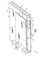
Figure 1 is a schematic view of an example two sided structural cold plate assembly. -
Figure 2 is a sectional view of the example two sided structural cold plate assembly. -
Figure 3 is a magnified sectional view of the example two sided structural cold plate assembly. - Referring to
Figure 1 , anexample support assembly 10 includes afixed structure 12 that supports a structuralcold plate assembly 14 for thermally controlling and coolingheat generating devices 26. In the disclosed example, the heat generatingdevices 26 are electronic devices that generate heat during operation. As appreciated, although electronic devices are described as examples, the disclosed structuralcold plate assembly 14 would be useful for any application requiring thermal management, including heating. - The example structural
cold plate assembly 14 includes apanel 16 that includes afirst side 18 and asecond side 20. Mounted to thefirst side 18 is a firstcold plate 22 and mounted to thesecond side 20 is a secondcold plate 24. Each of the first and secondcold plates devices 26. Thepanel 16 and thereby the first and secondcold plates mount 28 to thefixed structure 12. Thefixed structure 12 could be a cabinet, wall, bulkhead or other fixed structure that provides a desired location for thedevices 26. Moreover, althoughcold plates - The first and second
cold plates devices 26. Thedevices 26 are mounted in thermal contact with each of thecold plates devices 26 are mounted on the correspondingcold plate devices 26 are within the contemplation of this disclosure. - The cooling medium is supplied by the first and
second inlets first cooling plate 22. The cooling medium can include a cooling fluid, air, or gas along with a combination of fluid, air and gas that facilitate the removal of heat generated by thedevices 26. In this example thecooling plates inlets Figures 2 and3 ) through thepanel 16 to thesecond cooling plate 24. Thesecond cooling plate 24 includes first andsecond outlets - As appreciated, the cooling system may include a heat exchanger to dissipate heat absorbed by the cooling medium and a pump to power circulation of the cooling medium. Moreover, the example structural
cold plate assembly 14 provides for the use of different cooling mediums such as different types of fluid in each of the separate circuits to provide desired thermal control capabilities. Further, although the example structuralcooling plate assembly 14 includes two separate cooling circuits, one or more than two cooling circuits are also within the contemplation for use with the disclosed device. - Referring to
Figure 2 , theexample panel 16 includes atop face sheet 38 and abottom face sheet 40. Theexample face sheets face sheets example panel 16 includes ahoneycomb portion 42 that includes a plurality of open cells that is sandwiched between the top andbottom face sheets honeycomb portion 42 reduces the overall weight of thepanel 16 while providing a desired structural integrity and strength. Aframe structure 44 is also disposed between the twoface sheets panel 16. Theframe structure 44 also provides a location into which fasteners can be inserted. - The
example face sheets honeycomb portion 42 and theframe structure 44. The example adhesive is selected to provide the desired bond between thehoneycomb portion 42, theframe structure 44 and theface sheets cold plate assembly 14. - An
insert 46 is disposed within thepanel 16 in the area where thetubes 60 extend. Thepanel 16 can also includealignment pins 45 that locate thecold plates panel 16. Other alignment and fastening features could also be included to secure and maintain thecold plates panel 16. - Referring to
Figure 3 with continued reference toFigure 2 , the first and secondcold plates cold plate 22 is defined by thecircuit plates 48 and 50 (Figure 3 ) and the fluid circuits for the secondcold plate 24 are defined by thecircuit plates top plate 56 and abottom plate 58. Thetop plates 56 provide a surface on which thedevices 26 are mounted. Moreover thetop plates 56 are constructed of a material that provides for the transfer of thermal energy from the devices mounted thereon to the fluid medium flowing within thecooling plates - In this example, a first complete fluid circuit is defined by the
circuit plate 50 of the firstcold plate 22 and thecircuit plate 54 of the secondcold plate 24. A second complete fluid circuit is defined by thecircuit plate 48 of the firstcold plate 22 and thecircuit plate 52 of the secondcold plate 24. The specific configuration of the first and second fluid circuits are arranged to provide a desired thermal capacity for absorbing heat from thedevices 26. - The fluid medium is directed from the first
cold plate 22 throughopenings 64 in thepanel 16 to the secondcold plate 24. In this example, theopenings 64 receivetubes 60 that are sealed to theplates 58 of thecold plates tubes 60 provide the fluid communication as conduits between the cold plates and the corresponding fluid circuits. - The
tubes 60 are installed through openings in thepanel 16 that are created within aninsert 46.Additional openings 64 are provided in thecold plates tubes 60. Theexample tubes 60 are welded at theinterface 66 with theplates 58 of the first and secondcold plates welded interface 66 may extend downwardly such that theinsert 46 is also at least partly welded to thetubes 60. In the disclosed example, thetubes 60 are sealed using an electron beam welding process. The electron beam directs energy along theinterface 66 to provide a desired fluid tight seal. Theopenings 64 in thecold plates - Once the
tubes 60 are welded in place, theopenings 64 in thecold plates caps 62. The example caps 62 seat onto aledge 68 formed at the interface between the circuit plates of eachcold plate cap 62 is then welded in place to seal and hold it in place. - The welding operation generates heat that radiates into the
panel 16 and thereby could affect the adhesive utilized to bond the face sheets to thehoneycomb portion 42 and theframe structure 44. Accordingly, in this example aninsert 46 is provided in the location where thetubes 60 are assembled. Theexample insert 46 defines the openings for thetubes 60. Further, the insert is not bonded to theface sheets tube weld interface 66. Instead, theinsert 46 defines aportion 70 of thetop side 18, and a corresponding part of the bottom side (not shown). - Because the
tubes 60 extend through thepanel 16, additional external inlets, outlets, connectors, conduits, tubes are not required. Therefore thetubes 60 provide a robust fluid communication passage between the first and secondcold plates - The example structural
cooling plate assembly 14 is fabricated by first assembling thepanel 16. Theexample panel 16 is assembled by bonding thetop face sheet 38 and thebottom face sheet 40 to thehoneycomb portion 42 andframe structure 44. In the location through which thetubes 60 will extend, theinsert 46 is positioned and bonded by way of an adhesive. As is shown inFigure 3 , theinsert 46 provides aportion 70 that is not covered by theface sheet 38. This configuration spaces the adhesively bonded portions of thetop face sheet 38 away from areas that are exposed to heat during welding operations. - The first and second
cold plates example cold plates cold plates panel 16. Theopenings 64 are then either created, or aligned through each of thecold plates cold plates openings 64 that are aligned with the passages through theinsert 46. Once thecold plates tubes 60 are inserted. - The
tubes 60 are inserted such that each of the first and second ends of thetubes 60 form a substantially flush interface with theplates 58 of each correspondingcold plate tube 60 and each of theplates 58 and theinsert 46. The continuous weld provides a desired strength and provides a desired fluid tight seal. In the disclosed example, twotubes 60 are inserted and welded in place. As appreciated, other numbers of tubes could be utilized as are desired to provide the desired fluid passage betweencold plates - In the disclosed example, the
cold plates fluid circuit plates cold plate 22 and thefluid circuit plates cold plate 24 are arranged to channel the fluid medium through a corresponding one of thetubes 60. This provides a complete fluid circuit that begins at one of theinlets cold plate 22, through the corresponding one of thefluid circuit plates tubes 60, through the correspondingfluid circuit plate cold plate 24 and out one of theoutlets 34, 36 (Figure 1 ). A second complete fluid circuit is defined in the same manner through those fluid circuit plates not used for the first fluid circuit. - Accordingly, the example structural
cold plate assembly 14 provides a two sided thermal control structure that is built into the support structure and that reduces the number of exposed fluid conduits and connectors. Moreover, the integral structure of the disclosed structuralcold plate assembly 14 aids in assembly and reduces overall package size and weight. - Although an example embodiment has been disclosed, a worker of ordinary skill in this art would recognize that certain modifications would come within the scope of this disclosure. For that reason, the following claims should be studied to determine the scope and content of this invention.
Claims (15)
- A cold plate assembly (14) comprising:a support structure (16) including first (18) and second (20) opposite sides;a first cold plate (22) disposed on the first side of the support structure;a second cold plate (24) disposed on the second side of the support structure; anda conduit (60) extending through the support structure for communicating fluid between the first cold plate and the second cold plate.
- The cold plate assembly as recited in claim 1, wherein the conduit (60) comprises a tube extending through the support structure (16).
- The cold plate assembly as recited in claim 2, wherein the tube (60) is welded to a portion of the first cold plate (22) and a portion of the second cold plate (24).
- The cold plate assembly as recited in claim 1, 2 or 3, wherein each of the first and second cold plates (22,24) comprises a bottom plate (58) mounted to a corresponding one of the first and second side (18,20) of the support structure, and the conduit (60) is joined to the bottom plate of each of the first and second cold plates.
- The cold plate assembly as recited in any one of claims 1 to 4, wherein the support structure (16) comprises an interior structure (42,44) sandwiched between face sheets (38,40) on each of the first and second sides.
- The cold plate assembly as recited in claim 5, wherein the interior structure comprises a frame (44) and a cellular structure (42) disposed between the first and second sides.
- The cold plate assembly as recited in any preceding claim, wherein each of the first and second cold plates (22,24) comprises a first cooling circuit and a second cooling circuit that is separate from the first cooling circuit.
- The cold plate assembly as recited in claim 7, wherein the conduit (60) comprises a first conduit that communicates fluid through the support structure (16) between the first cooling circuit in the first cold plate (22) and the first cooling circuit in the second cold plate (24), and a second conduit communicates fluid through the support structure between the second cooling circuit of the first cooling plate (22) and the second cooling circuit of the second cooling plate (24).
- The cold plate assembly as recited in claim 8, including an opening (64) through each of the cold plates proximate each of the first and second conduits and a cap (62) disposed over each of the openings for sealing the openings.
- The cold plate assembly of any preceding claim, wherein the support structure is:a panel.
- The cold plate assembly as recited in any preceding claim, including an insert (46) disposed within the support structure (16) and the conduit (60) extends through the insert.
- The cold plate assembly as recited in claim 7 or any one of claims 8 to 11 when dependent on claim 7, including a first inlet (30) mounted to the first cold plate (22) for communicating a fluid medium to the first fluid circuit and a second inlet (32) mounted to the first cold plate (22) for communicating a second fluid medium to the second fluid circuit.
- The cold plate assembly as recited in any preceding claim, including at least one alignment pin (45) for positioning at least one of the first cold plate (22) and the second cold plate (24) on the support structure (16).
- A method of assembling a structural support for a heat generating device, the method comprising:assembling a panel (16) including a first side (18) and a second side (20);mounting a first cold plate (22) to the first side of the panel;mounting a second cold plate (24) to the second side of the panel; andinserting a tube (60) into a space between the first and second sides of the panel to create a passage for a cooling medium through the panel between the first cold plate and the second cold plate.
- The method as recited in claim 14, including the step of sealing each end of the tube (60) to a corresponding one of the first and second cold plates (22,24) and preferably including the step of welding one end of the tube (60) to the first cold plate (22) and welding a second end of the tube to the second cold plate (24) to create a seal.
Applications Claiming Priority (1)
| Application Number | Priority Date | Filing Date | Title |
|---|---|---|---|
| US12/748,552 US8991478B2 (en) | 2010-03-29 | 2010-03-29 | Compact two sided cold plate with transfer tubes |
Publications (3)
| Publication Number | Publication Date |
|---|---|
| EP2372760A2 true EP2372760A2 (en) | 2011-10-05 |
| EP2372760A3 EP2372760A3 (en) | 2012-12-26 |
| EP2372760B1 EP2372760B1 (en) | 2019-10-23 |
Family
ID=44343149
Family Applications (1)
| Application Number | Title | Priority Date | Filing Date |
|---|---|---|---|
| EP11250351.1A Active EP2372760B1 (en) | 2010-03-29 | 2011-03-21 | Compact two sided cold plate support assembly with transfer tubes |
Country Status (4)
| Country | Link |
|---|---|
| US (1) | US8991478B2 (en) |
| EP (1) | EP2372760B1 (en) |
| JP (1) | JP5192561B2 (en) |
| CN (1) | CN102209457A (en) |
Cited By (6)
| Publication number | Priority date | Publication date | Assignee | Title |
|---|---|---|---|---|
| WO2014207185A1 (en) * | 2013-06-28 | 2014-12-31 | TRUMPF Hüttinger GmbH + Co. KG | Cooling device for cooling an electronic component and electronic arrangement with a cooling device |
| EP2645838A3 (en) * | 2012-03-26 | 2016-09-14 | Hamilton Sundstrand Space Systems International, Inc. | Structural assembly for cold plate cooling |
| EP2672798A3 (en) * | 2012-06-07 | 2017-01-25 | Hamilton Sundstrand Space Systems International, Inc. | Compact two sided cold plate with floating transfer tubes |
| US9825343B2 (en) | 2014-09-30 | 2017-11-21 | Johnson Controls Technology Company | Battery module passive thermal management features and positioning |
| US10658717B2 (en) | 2014-09-30 | 2020-05-19 | Cps Technology Holdings Llc | Battery module active thermal management features and positioning |
| US10720683B2 (en) | 2014-09-30 | 2020-07-21 | Cps Technology Holdings Llc | Battery module thermal management features for internal flow |
Families Citing this family (13)
| Publication number | Priority date | Publication date | Assignee | Title |
|---|---|---|---|---|
| US8991478B2 (en) | 2010-03-29 | 2015-03-31 | Hamilton Sundstrand Space Systems International, Inc. | Compact two sided cold plate with transfer tubes |
| US8797741B2 (en) * | 2010-10-21 | 2014-08-05 | Raytheon Company | Maintaining thermal uniformity in micro-channel cold plates with two-phase flows |
| JP6409556B2 (en) * | 2014-12-19 | 2018-10-24 | 富士通株式会社 | Substrate with cooling mechanism and electronic device |
| CN105511577A (en) * | 2015-12-08 | 2016-04-20 | 山东超越数控电子有限公司 | High heating flux module heat dissipation method combining uniform temperature plate and liquid cooling |
| CN106270685A (en) * | 2016-08-26 | 2017-01-04 | 蚌埠市勇创机械电子有限公司 | A kind of dust-collecting type circuit board groove milling system |
| US10188223B2 (en) | 2016-09-26 | 2019-01-29 | Hussmann Corporation | Refrigerated merchandiser including eutectic plate refrigeration |
| GB2584991B (en) * | 2019-05-21 | 2022-01-26 | Iceotope Group Ltd | Cold plate |
| US12092405B2 (en) * | 2021-12-03 | 2024-09-17 | Dell Products, L.P. | Smart cold plate for redundant liquid cooling loops |
| US12471245B2 (en) * | 2023-06-30 | 2025-11-11 | Rivian Ip Holdings, Llc | Cold plate |
| US12542330B2 (en) | 2023-06-30 | 2026-02-03 | Rivian Ip Holdings, Llc | Battery subassembly with potting material |
| US12525671B2 (en) | 2023-06-30 | 2026-01-13 | Rivian Ip Holdings, Llc | Battery welds |
| US20250240920A1 (en) * | 2024-01-23 | 2025-07-24 | Microsoft Technology Licensing, Llc | Systems and methods for liquid cooling of multicomponent packages |
| US20250377172A1 (en) * | 2024-06-10 | 2025-12-11 | Coolit Systems, Inc. | Fluid heat exchangers with improved cooling |
Family Cites Families (49)
| Publication number | Priority date | Publication date | Assignee | Title |
|---|---|---|---|---|
| US3327776A (en) * | 1965-10-24 | 1967-06-27 | Trane Co | Heat exchanger |
| US3676642A (en) * | 1970-04-17 | 1972-07-11 | Nordson Corp | Modular apparatus for heating circulating coating material |
| US4196775A (en) * | 1977-09-19 | 1980-04-08 | The Unites States Of America As Represented By The Secretary Of The Navy | Shock-mounted, liquid cooled cold plate assembly |
| US4432918A (en) * | 1981-08-24 | 1984-02-21 | Corning Glass Works | Methods for fabricating selectively plugged honeycomb structures |
| US4478277A (en) * | 1982-06-28 | 1984-10-23 | The Trane Company | Heat exchanger having uniform surface temperature and improved structural strength |
| US5088005A (en) * | 1990-05-08 | 1992-02-11 | Sundstrand Corporation | Cold plate for cooling electronics |
| JP3254001B2 (en) | 1991-04-08 | 2002-02-04 | ゼネラル・エレクトリック・カンパニイ | Integrated radiator for semiconductor module |
| JP2814868B2 (en) * | 1992-06-17 | 1998-10-27 | 三菱電機株式会社 | Plate type heat exchanger and method of manufacturing the same |
| US5269372A (en) * | 1992-12-21 | 1993-12-14 | International Business Machines Corporation | Intersecting flow network for a cold plate cooling system |
| FR2701600B1 (en) * | 1993-02-10 | 1995-09-08 | Gec Alsthom Transport Sa | DEVICE FOR COOLING ELECTRIC POWER COMPONENTS. |
| US5484015A (en) * | 1993-12-03 | 1996-01-16 | Kyees; Melvin | Cold plate and method of making same |
| JPH0853100A (en) * | 1994-08-10 | 1996-02-27 | Mitsubishi Electric Corp | Honeycomb sandwich panel with embedded heat pipe |
| DE19600166A1 (en) | 1996-01-04 | 1997-07-17 | Daimler Benz Ag | Cooling body |
| JP2992476B2 (en) | 1996-03-15 | 1999-12-20 | 川崎重工業株式会社 | Manufacturing method of cold plate for space equipment |
| US5740015A (en) * | 1996-05-02 | 1998-04-14 | Chrysler Corporation | Heat exchanger |
| US6034872A (en) * | 1997-07-16 | 2000-03-07 | International Business Machines Corporation | Cooling computer systems |
| US6191945B1 (en) * | 1997-07-30 | 2001-02-20 | Hewlett-Packard Company | Cold plate arrangement for cooling processor and companion voltage regulator |
| US5923533A (en) * | 1998-02-17 | 1999-07-13 | Lockheed Martin Corporation | Multiple tile scaleable cooling system for semiconductor components |
| US6230790B1 (en) * | 1999-05-10 | 2001-05-15 | Lockheed Martin Corporation | Thermal control system for spacecraft |
| US6349035B1 (en) * | 2000-09-29 | 2002-02-19 | Compaq Information Technologies Group, L.P. | Method and apparatus for tooless mating of liquid cooled cold plate with tapered interposer heat sink |
| EP1225633A1 (en) | 2001-01-22 | 2002-07-24 | ABB Schweiz AG | Kühler zur Kühlung eines Leistungshalbleiterbauelements bzw.-Moduls sowie Verfahren zum Herstellen eines solchen Kühlers |
| US6661133B2 (en) * | 2001-07-12 | 2003-12-09 | Eli Liebermann | Rotor cooling arrangement |
| JP2003051689A (en) * | 2001-08-06 | 2003-02-21 | Toshiba Corp | Cooling device for heating element |
| US7220365B2 (en) * | 2001-08-13 | 2007-05-22 | New Qu Energy Ltd. | Devices using a medium having a high heat transfer rate |
| US6679315B2 (en) * | 2002-01-14 | 2004-01-20 | Marconi Communications, Inc. | Small scale chip cooler assembly |
| DE10207873A1 (en) * | 2002-02-23 | 2003-09-04 | Modine Mfg Co | Cooling device for electronic or electrical components in motor vehicle, has container adjoining cooling fluid flow channel for receiving heat lost from components |
| US6967064B2 (en) * | 2002-06-24 | 2005-11-22 | Delphi Technologies, Inc. | Co-flow anode/cathode supply heat exchanger for a solid-oxide fuel cell assembly |
| US7000684B2 (en) * | 2002-11-01 | 2006-02-21 | Cooligy, Inc. | Method and apparatus for efficient vertical fluid delivery for cooling a heat producing device |
| US7188488B2 (en) * | 2003-03-12 | 2007-03-13 | Hamilton Sundstrand | Pack and a half condensing cycle pack with combined heat exchangers |
| US7017654B2 (en) * | 2003-03-17 | 2006-03-28 | Cooligy, Inc. | Apparatus and method of forming channels in a heat-exchanging device |
| US7024874B2 (en) * | 2003-09-22 | 2006-04-11 | Hamilton Sundstrand | Aircraft galley chiller system |
| US7188662B2 (en) * | 2004-06-04 | 2007-03-13 | Cooligy, Inc. | Apparatus and method of efficient fluid delivery for cooling a heat producing device |
| US7306027B2 (en) * | 2004-07-01 | 2007-12-11 | Aavid Thermalloy, Llc | Fluid-containing cooling plate for an electronic component |
| US7149087B2 (en) * | 2004-09-08 | 2006-12-12 | Thermal Corp. | Liquid cooled heat sink with cold plate retention mechanism |
| US7230334B2 (en) * | 2004-11-12 | 2007-06-12 | International Business Machines Corporation | Semiconductor integrated circuit chip packages having integrated microchannel cooling modules |
| US7521789B1 (en) * | 2004-12-18 | 2009-04-21 | Rinehart Motion Systems, Llc | Electrical assembly having heat sink protrusions |
| US7201217B2 (en) * | 2005-05-24 | 2007-04-10 | Raytheon Company | Cold plate assembly |
| US7673389B2 (en) * | 2005-07-19 | 2010-03-09 | International Business Machines Corporation | Cold plate apparatus and method of fabrication thereof with a controlled heat transfer characteristic between a metallurgically bonded tube and heat sink for facilitating cooling of an electronics component |
| DE102005034998B4 (en) * | 2005-07-27 | 2016-06-23 | Behr Industry Gmbh & Co. Kg | Method for producing a device for cooling electronic components and device for cooling electronic components |
| US7353864B2 (en) * | 2005-12-23 | 2008-04-08 | Hamilton Sundstrand Corporation | Apparatus for reducing thermal fatigue in heat exchanger cores |
| TW200805042A (en) * | 2006-02-16 | 2008-01-16 | Cooligy Inc | Liquid cooling loops for server applications |
| US7551439B2 (en) * | 2006-03-28 | 2009-06-23 | Delphi Technologies, Inc. | Fluid cooled electronic assembly |
| JP5021290B2 (en) | 2006-12-22 | 2012-09-05 | 株式会社ティラド | HELIBOON TYPE LIQUID COOLING HEAT SINK AND ITS MANUFACTURING METHOD |
| JP2008171840A (en) | 2007-01-05 | 2008-07-24 | T Rad Co Ltd | Liquid-cooled heat sink and design method thereof |
| US8011200B2 (en) * | 2007-02-19 | 2011-09-06 | Liebert Corporation | Cooling fluid flow regulation distribution system and method |
| US7499279B2 (en) * | 2007-04-30 | 2009-03-03 | International Business Machines Corporation | Cold plate stability |
| US20090211977A1 (en) * | 2008-02-27 | 2009-08-27 | Oregon State University | Through-plate microchannel transfer devices |
| US8991478B2 (en) | 2010-03-29 | 2015-03-31 | Hamilton Sundstrand Space Systems International, Inc. | Compact two sided cold plate with transfer tubes |
| CN102008576B (en) | 2010-11-29 | 2012-05-30 | 昆明理工大学 | A kind of external Chinese medicine for treating sprain and preparation method thereof |
-
2010
- 2010-03-29 US US12/748,552 patent/US8991478B2/en active Active
-
2011
- 2011-03-21 EP EP11250351.1A patent/EP2372760B1/en active Active
- 2011-03-29 JP JP2011071278A patent/JP5192561B2/en not_active Expired - Fee Related
- 2011-03-29 CN CN2011100764967A patent/CN102209457A/en active Pending
Non-Patent Citations (1)
| Title |
|---|
| None |
Cited By (8)
| Publication number | Priority date | Publication date | Assignee | Title |
|---|---|---|---|---|
| EP2645838A3 (en) * | 2012-03-26 | 2016-09-14 | Hamilton Sundstrand Space Systems International, Inc. | Structural assembly for cold plate cooling |
| EP2672798A3 (en) * | 2012-06-07 | 2017-01-25 | Hamilton Sundstrand Space Systems International, Inc. | Compact two sided cold plate with floating transfer tubes |
| WO2014207185A1 (en) * | 2013-06-28 | 2014-12-31 | TRUMPF Hüttinger GmbH + Co. KG | Cooling device for cooling an electronic component and electronic arrangement with a cooling device |
| US10076057B2 (en) | 2013-06-28 | 2018-09-11 | Trumpf Huettinger Gmbh + Co. Kg | Electronic component cooling |
| US10506741B2 (en) | 2013-06-28 | 2019-12-10 | Trumpf Huettinger Gmbh + Co. Kg | Electronic component cooling |
| US9825343B2 (en) | 2014-09-30 | 2017-11-21 | Johnson Controls Technology Company | Battery module passive thermal management features and positioning |
| US10658717B2 (en) | 2014-09-30 | 2020-05-19 | Cps Technology Holdings Llc | Battery module active thermal management features and positioning |
| US10720683B2 (en) | 2014-09-30 | 2020-07-21 | Cps Technology Holdings Llc | Battery module thermal management features for internal flow |
Also Published As
| Publication number | Publication date |
|---|---|
| CN102209457A (en) | 2011-10-05 |
| EP2372760A3 (en) | 2012-12-26 |
| JP5192561B2 (en) | 2013-05-08 |
| US20110232879A1 (en) | 2011-09-29 |
| JP2011211202A (en) | 2011-10-20 |
| US8991478B2 (en) | 2015-03-31 |
| EP2372760B1 (en) | 2019-10-23 |
Similar Documents
| Publication | Publication Date | Title |
|---|---|---|
| US8991478B2 (en) | Compact two sided cold plate with transfer tubes | |
| EP2372290B1 (en) | Compact two side cold plate support assembly with threaded inserts | |
| CN107078243B (en) | Battery module with cell fixation | |
| US11870048B2 (en) | Thermal systems for battery electric vehicles | |
| WO2022062528A1 (en) | Liquid-cooled battery system and liquid-cooled battery system control method | |
| EP3923400B1 (en) | Battery pack | |
| CN103219558A (en) | Power battery temperature adjusting device and making method thereof | |
| CN106374066A (en) | Battery device and method | |
| JP5516166B2 (en) | Vehicle power supply | |
| WO2021249272A1 (en) | Battery pack and electric vehicle | |
| US11482743B2 (en) | Method for producing a high-voltage energy storage device for a motor vehicle, and high-voltage energy storage device for a motor vehicle | |
| US9331368B2 (en) | Battery module | |
| CA3123988C (en) | Heat exchanger for flammable refrigerants | |
| CN111092177A (en) | Accumulator device | |
| CN115149192A (en) | Vehicle battery case and manufacturing method of vehicle battery case | |
| CN105027405B (en) | cooling structure | |
| CN214842717U (en) | Heat exchange device and battery pack | |
| US20120231319A1 (en) | Structural and thermal management component | |
| CN113844247B (en) | A battery pack and electric vehicle | |
| CN111430621B (en) | Battery pack | |
| EP2672798A2 (en) | Compact two sided cold plate with floating transfer tubes | |
| CN218414856U (en) | Battery pack and electric equipment | |
| US20240409006A1 (en) | Electric vehicle with battery thermal management system | |
| WO2026066465A1 (en) | Temperature regulation device, electronic control system, chassis and vehicle | |
| CN119239221A (en) | Thermal management device and vehicle |
Legal Events
| Date | Code | Title | Description |
|---|---|---|---|
| PUAI | Public reference made under article 153(3) epc to a published international application that has entered the european phase |
Free format text: ORIGINAL CODE: 0009012 |
|
| AK | Designated contracting states |
Kind code of ref document: A2 Designated state(s): AL AT BE BG CH CY CZ DE DK EE ES FI FR GB GR HR HU IE IS IT LI LT LU LV MC MK MT NL NO PL PT RO RS SE SI SK SM TR |
|
| AX | Request for extension of the european patent |
Extension state: BA ME |
|
| PUAL | Search report despatched |
Free format text: ORIGINAL CODE: 0009013 |
|
| AK | Designated contracting states |
Kind code of ref document: A3 Designated state(s): AL AT BE BG CH CY CZ DE DK EE ES FI FR GB GR HR HU IE IS IT LI LT LU LV MC MK MT NL NO PL PT RO RS SE SI SK SM TR |
|
| AX | Request for extension of the european patent |
Extension state: BA ME |
|
| RIC1 | Information provided on ipc code assigned before grant |
Ipc: H05K 7/20 20060101ALI20121122BHEP Ipc: H01L 23/473 20060101AFI20121122BHEP |
|
| 17P | Request for examination filed |
Effective date: 20130626 |
|
| RBV | Designated contracting states (corrected) |
Designated state(s): AL AT BE BG CH CY CZ DE DK EE ES FI FR GB GR HR HU IE IS IT LI LT LU LV MC MK MT NL NO PL PT RO RS SE SI SK SM TR |
|
| RAP1 | Party data changed (applicant data changed or rights of an application transferred) |
Owner name: HAMILTON SUNDSTRAND SPACE SYSTEMS INTERNATIONAL, I |
|
| 17Q | First examination report despatched |
Effective date: 20160421 |
|
| GRAP | Despatch of communication of intention to grant a patent |
Free format text: ORIGINAL CODE: EPIDOSNIGR1 |
|
| STAA | Information on the status of an ep patent application or granted ep patent |
Free format text: STATUS: GRANT OF PATENT IS INTENDED |
|
| INTG | Intention to grant announced |
Effective date: 20190503 |
|
| GRAS | Grant fee paid |
Free format text: ORIGINAL CODE: EPIDOSNIGR3 |
|
| GRAA | (expected) grant |
Free format text: ORIGINAL CODE: 0009210 |
|
| STAA | Information on the status of an ep patent application or granted ep patent |
Free format text: STATUS: THE PATENT HAS BEEN GRANTED |
|
| AK | Designated contracting states |
Kind code of ref document: B1 Designated state(s): AL AT BE BG CH CY CZ DE DK EE ES FI FR GB GR HR HU IE IS IT LI LT LU LV MC MK MT NL NO PL PT RO RS SE SI SK SM TR |
|
| REG | Reference to a national code |
Ref country code: GB Ref legal event code: FG4D |
|
| REG | Reference to a national code |
Ref country code: CH Ref legal event code: EP |
|
| REG | Reference to a national code |
Ref country code: IE Ref legal event code: FG4D |
|
| REG | Reference to a national code |
Ref country code: DE Ref legal event code: R096 Ref document number: 602011062875 Country of ref document: DE |
|
| REG | Reference to a national code |
Ref country code: AT Ref legal event code: REF Ref document number: 1194653 Country of ref document: AT Kind code of ref document: T Effective date: 20191115 |
|
| REG | Reference to a national code |
Ref country code: NL Ref legal event code: MP Effective date: 20191023 |
|
| REG | Reference to a national code |
Ref country code: LT Ref legal event code: MG4D |
|
| PG25 | Lapsed in a contracting state [announced via postgrant information from national office to epo] |
Ref country code: PT Free format text: LAPSE BECAUSE OF FAILURE TO SUBMIT A TRANSLATION OF THE DESCRIPTION OR TO PAY THE FEE WITHIN THE PRESCRIBED TIME-LIMIT Effective date: 20200224 Ref country code: BG Free format text: LAPSE BECAUSE OF FAILURE TO SUBMIT A TRANSLATION OF THE DESCRIPTION OR TO PAY THE FEE WITHIN THE PRESCRIBED TIME-LIMIT Effective date: 20200123 Ref country code: FI Free format text: LAPSE BECAUSE OF FAILURE TO SUBMIT A TRANSLATION OF THE DESCRIPTION OR TO PAY THE FEE WITHIN THE PRESCRIBED TIME-LIMIT Effective date: 20191023 Ref country code: GR Free format text: LAPSE BECAUSE OF FAILURE TO SUBMIT A TRANSLATION OF THE DESCRIPTION OR TO PAY THE FEE WITHIN THE PRESCRIBED TIME-LIMIT Effective date: 20200124 Ref country code: PL Free format text: LAPSE BECAUSE OF FAILURE TO SUBMIT A TRANSLATION OF THE DESCRIPTION OR TO PAY THE FEE WITHIN THE PRESCRIBED TIME-LIMIT Effective date: 20191023 Ref country code: NO Free format text: LAPSE BECAUSE OF FAILURE TO SUBMIT A TRANSLATION OF THE DESCRIPTION OR TO PAY THE FEE WITHIN THE PRESCRIBED TIME-LIMIT Effective date: 20200123 Ref country code: LV Free format text: LAPSE BECAUSE OF FAILURE TO SUBMIT A TRANSLATION OF THE DESCRIPTION OR TO PAY THE FEE WITHIN THE PRESCRIBED TIME-LIMIT Effective date: 20191023 Ref country code: SE Free format text: LAPSE BECAUSE OF FAILURE TO SUBMIT A TRANSLATION OF THE DESCRIPTION OR TO PAY THE FEE WITHIN THE PRESCRIBED TIME-LIMIT Effective date: 20191023 Ref country code: NL Free format text: LAPSE BECAUSE OF FAILURE TO SUBMIT A TRANSLATION OF THE DESCRIPTION OR TO PAY THE FEE WITHIN THE PRESCRIBED TIME-LIMIT Effective date: 20191023 Ref country code: ES Free format text: LAPSE BECAUSE OF FAILURE TO SUBMIT A TRANSLATION OF THE DESCRIPTION OR TO PAY THE FEE WITHIN THE PRESCRIBED TIME-LIMIT Effective date: 20191023 Ref country code: LT Free format text: LAPSE BECAUSE OF FAILURE TO SUBMIT A TRANSLATION OF THE DESCRIPTION OR TO PAY THE FEE WITHIN THE PRESCRIBED TIME-LIMIT Effective date: 20191023 |
|
| PG25 | Lapsed in a contracting state [announced via postgrant information from national office to epo] |
Ref country code: RS Free format text: LAPSE BECAUSE OF FAILURE TO SUBMIT A TRANSLATION OF THE DESCRIPTION OR TO PAY THE FEE WITHIN THE PRESCRIBED TIME-LIMIT Effective date: 20191023 Ref country code: HR Free format text: LAPSE BECAUSE OF FAILURE TO SUBMIT A TRANSLATION OF THE DESCRIPTION OR TO PAY THE FEE WITHIN THE PRESCRIBED TIME-LIMIT Effective date: 20191023 Ref country code: IS Free format text: LAPSE BECAUSE OF FAILURE TO SUBMIT A TRANSLATION OF THE DESCRIPTION OR TO PAY THE FEE WITHIN THE PRESCRIBED TIME-LIMIT Effective date: 20200224 |
|
| PG25 | Lapsed in a contracting state [announced via postgrant information from national office to epo] |
Ref country code: AL Free format text: LAPSE BECAUSE OF FAILURE TO SUBMIT A TRANSLATION OF THE DESCRIPTION OR TO PAY THE FEE WITHIN THE PRESCRIBED TIME-LIMIT Effective date: 20191023 |
|
| REG | Reference to a national code |
Ref country code: DE Ref legal event code: R097 Ref document number: 602011062875 Country of ref document: DE |
|
| PG2D | Information on lapse in contracting state deleted |
Ref country code: IS |
|
| PG25 | Lapsed in a contracting state [announced via postgrant information from national office to epo] |
Ref country code: DK Free format text: LAPSE BECAUSE OF FAILURE TO SUBMIT A TRANSLATION OF THE DESCRIPTION OR TO PAY THE FEE WITHIN THE PRESCRIBED TIME-LIMIT Effective date: 20191023 Ref country code: EE Free format text: LAPSE BECAUSE OF FAILURE TO SUBMIT A TRANSLATION OF THE DESCRIPTION OR TO PAY THE FEE WITHIN THE PRESCRIBED TIME-LIMIT Effective date: 20191023 Ref country code: CZ Free format text: LAPSE BECAUSE OF FAILURE TO SUBMIT A TRANSLATION OF THE DESCRIPTION OR TO PAY THE FEE WITHIN THE PRESCRIBED TIME-LIMIT Effective date: 20191023 Ref country code: RO Free format text: LAPSE BECAUSE OF FAILURE TO SUBMIT A TRANSLATION OF THE DESCRIPTION OR TO PAY THE FEE WITHIN THE PRESCRIBED TIME-LIMIT Effective date: 20191023 Ref country code: IS Free format text: LAPSE BECAUSE OF FAILURE TO SUBMIT A TRANSLATION OF THE DESCRIPTION OR TO PAY THE FEE WITHIN THE PRESCRIBED TIME-LIMIT Effective date: 20200223 |
|
| REG | Reference to a national code |
Ref country code: AT Ref legal event code: MK05 Ref document number: 1194653 Country of ref document: AT Kind code of ref document: T Effective date: 20191023 |
|
| PLBE | No opposition filed within time limit |
Free format text: ORIGINAL CODE: 0009261 |
|
| STAA | Information on the status of an ep patent application or granted ep patent |
Free format text: STATUS: NO OPPOSITION FILED WITHIN TIME LIMIT |
|
| PG25 | Lapsed in a contracting state [announced via postgrant information from national office to epo] |
Ref country code: SM Free format text: LAPSE BECAUSE OF FAILURE TO SUBMIT A TRANSLATION OF THE DESCRIPTION OR TO PAY THE FEE WITHIN THE PRESCRIBED TIME-LIMIT Effective date: 20191023 Ref country code: SK Free format text: LAPSE BECAUSE OF FAILURE TO SUBMIT A TRANSLATION OF THE DESCRIPTION OR TO PAY THE FEE WITHIN THE PRESCRIBED TIME-LIMIT Effective date: 20191023 |
|
| 26N | No opposition filed |
Effective date: 20200724 |
|
| PG25 | Lapsed in a contracting state [announced via postgrant information from national office to epo] |
Ref country code: MC Free format text: LAPSE BECAUSE OF FAILURE TO SUBMIT A TRANSLATION OF THE DESCRIPTION OR TO PAY THE FEE WITHIN THE PRESCRIBED TIME-LIMIT Effective date: 20191023 |
|
| REG | Reference to a national code |
Ref country code: CH Ref legal event code: PL |
|
| PG25 | Lapsed in a contracting state [announced via postgrant information from national office to epo] |
Ref country code: AT Free format text: LAPSE BECAUSE OF FAILURE TO SUBMIT A TRANSLATION OF THE DESCRIPTION OR TO PAY THE FEE WITHIN THE PRESCRIBED TIME-LIMIT Effective date: 20191023 Ref country code: SI Free format text: LAPSE BECAUSE OF FAILURE TO SUBMIT A TRANSLATION OF THE DESCRIPTION OR TO PAY THE FEE WITHIN THE PRESCRIBED TIME-LIMIT Effective date: 20191023 |
|
| REG | Reference to a national code |
Ref country code: BE Ref legal event code: MM Effective date: 20200331 |
|
| PG25 | Lapsed in a contracting state [announced via postgrant information from national office to epo] |
Ref country code: LU Free format text: LAPSE BECAUSE OF NON-PAYMENT OF DUE FEES Effective date: 20200321 |
|
| PG25 | Lapsed in a contracting state [announced via postgrant information from national office to epo] |
Ref country code: IE Free format text: LAPSE BECAUSE OF NON-PAYMENT OF DUE FEES Effective date: 20200321 Ref country code: LI Free format text: LAPSE BECAUSE OF NON-PAYMENT OF DUE FEES Effective date: 20200331 Ref country code: CH Free format text: LAPSE BECAUSE OF NON-PAYMENT OF DUE FEES Effective date: 20200331 |
|
| PG25 | Lapsed in a contracting state [announced via postgrant information from national office to epo] |
Ref country code: BE Free format text: LAPSE BECAUSE OF NON-PAYMENT OF DUE FEES Effective date: 20200331 |
|
| PG25 | Lapsed in a contracting state [announced via postgrant information from national office to epo] |
Ref country code: TR Free format text: LAPSE BECAUSE OF FAILURE TO SUBMIT A TRANSLATION OF THE DESCRIPTION OR TO PAY THE FEE WITHIN THE PRESCRIBED TIME-LIMIT Effective date: 20191023 Ref country code: MT Free format text: LAPSE BECAUSE OF FAILURE TO SUBMIT A TRANSLATION OF THE DESCRIPTION OR TO PAY THE FEE WITHIN THE PRESCRIBED TIME-LIMIT Effective date: 20191023 Ref country code: CY Free format text: LAPSE BECAUSE OF FAILURE TO SUBMIT A TRANSLATION OF THE DESCRIPTION OR TO PAY THE FEE WITHIN THE PRESCRIBED TIME-LIMIT Effective date: 20191023 |
|
| PG25 | Lapsed in a contracting state [announced via postgrant information from national office to epo] |
Ref country code: MK Free format text: LAPSE BECAUSE OF FAILURE TO SUBMIT A TRANSLATION OF THE DESCRIPTION OR TO PAY THE FEE WITHIN THE PRESCRIBED TIME-LIMIT Effective date: 20191023 |
|
| REG | Reference to a national code |
Ref country code: DE Ref legal event code: R079 Ref document number: 602011062875 Country of ref document: DE Free format text: PREVIOUS MAIN CLASS: H01L0023473000 Ipc: H10W0040470000 |
|
| P01 | Opt-out of the competence of the unified patent court (upc) registered |
Free format text: CASE NUMBER: UPC_APP_0016521_2372760/2025 Effective date: 20251209 |
|
| PGFP | Annual fee paid to national office [announced via postgrant information from national office to epo] |
Ref country code: GB Payment date: 20260219 Year of fee payment: 16 |
|
| PGFP | Annual fee paid to national office [announced via postgrant information from national office to epo] |
Ref country code: DE Payment date: 20260219 Year of fee payment: 16 |
|
| PGFP | Annual fee paid to national office [announced via postgrant information from national office to epo] |
Ref country code: IT Payment date: 20260219 Year of fee payment: 16 |
|
| PGFP | Annual fee paid to national office [announced via postgrant information from national office to epo] |
Ref country code: FR Payment date: 20260219 Year of fee payment: 16 |