EP2372487A2 - System zur Erzeugung von Solarenergie, Steuerungsvorrichtung und Steuerungsverfahren dafür - Google Patents
System zur Erzeugung von Solarenergie, Steuerungsvorrichtung und Steuerungsverfahren dafür Download PDFInfo
- Publication number
- EP2372487A2 EP2372487A2 EP20100197387 EP10197387A EP2372487A2 EP 2372487 A2 EP2372487 A2 EP 2372487A2 EP 20100197387 EP20100197387 EP 20100197387 EP 10197387 A EP10197387 A EP 10197387A EP 2372487 A2 EP2372487 A2 EP 2372487A2
- Authority
- EP
- European Patent Office
- Prior art keywords
- electric energy
- output
- branches
- multiple branches
- branch
- Prior art date
- Legal status (The legal status is an assumption and is not a legal conclusion. Google has not performed a legal analysis and makes no representation as to the accuracy of the status listed.)
- Withdrawn
Links
Images


Classifications
-
- H—ELECTRICITY
- H02—GENERATION; CONVERSION OR DISTRIBUTION OF ELECTRIC POWER
- H02J—ELECTRIC POWER NETWORKS; CIRCUIT ARRANGEMENTS OR SYSTEMS FOR SUPPLYING OR DISTRIBUTING ELECTRIC POWER; SYSTEMS FOR STORING ELECTRIC ENERGY
- H02J1/00—Circuit arrangements for DC mains or DC distribution networks
- H02J1/10—Parallel operation of DC sources
-
- H—ELECTRICITY
- H02—GENERATION; CONVERSION OR DISTRIBUTION OF ELECTRIC POWER
- H02J—ELECTRIC POWER NETWORKS; CIRCUIT ARRANGEMENTS OR SYSTEMS FOR SUPPLYING OR DISTRIBUTING ELECTRIC POWER; SYSTEMS FOR STORING ELECTRIC ENERGY
- H02J3/00—Circuit arrangements for AC mains or AC distribution networks
- H02J3/38—Arrangements for feeding a single network from two or more generators or sources in parallel; Arrangements for feeding already energised networks from additional generators or sources in parallel
- H02J3/381—Dispersed generators
-
- H—ELECTRICITY
- H02—GENERATION; CONVERSION OR DISTRIBUTION OF ELECTRIC POWER
- H02J—ELECTRIC POWER NETWORKS; CIRCUIT ARRANGEMENTS OR SYSTEMS FOR SUPPLYING OR DISTRIBUTING ELECTRIC POWER; SYSTEMS FOR STORING ELECTRIC ENERGY
- H02J3/00—Circuit arrangements for AC mains or AC distribution networks
- H02J3/38—Arrangements for feeding a single network from two or more generators or sources in parallel; Arrangements for feeding already energised networks from additional generators or sources in parallel
- H02J3/46—Controlling the sharing of generated power between the generators, sources or networks
-
- H—ELECTRICITY
- H02—GENERATION; CONVERSION OR DISTRIBUTION OF ELECTRIC POWER
- H02J—ELECTRIC POWER NETWORKS; CIRCUIT ARRANGEMENTS OR SYSTEMS FOR SUPPLYING OR DISTRIBUTING ELECTRIC POWER; SYSTEMS FOR STORING ELECTRIC ENERGY
- H02J2101/00—Supply or distribution of decentralised, dispersed or local electric power generation
- H02J2101/20—Dispersed power generation using renewable energy sources
- H02J2101/22—Solar energy
- H02J2101/24—Photovoltaics
- H02J2101/25—Photovoltaics involving maximum power point tracking control for photovoltaic sources
-
- H—ELECTRICITY
- H02—GENERATION; CONVERSION OR DISTRIBUTION OF ELECTRIC POWER
- H02M—APPARATUS FOR CONVERSION BETWEEN AC AND AC, BETWEEN AC AND DC, OR BETWEEN DC AND DC, AND FOR USE WITH MAINS OR SIMILAR POWER SUPPLY SYSTEMS; CONVERSION OF DC OR AC INPUT POWER INTO SURGE OUTPUT POWER; CONTROL OR REGULATION THEREOF
- H02M7/00—Conversion of AC power input into DC power output; Conversion of DC power input into AC power output
- H02M7/003—Constructional details, e.g. physical layout, assembly, wiring or busbar connections
-
- Y—GENERAL TAGGING OF NEW TECHNOLOGICAL DEVELOPMENTS; GENERAL TAGGING OF CROSS-SECTIONAL TECHNOLOGIES SPANNING OVER SEVERAL SECTIONS OF THE IPC; TECHNICAL SUBJECTS COVERED BY FORMER USPC CROSS-REFERENCE ART COLLECTIONS [XRACs] AND DIGESTS
- Y02—TECHNOLOGIES OR APPLICATIONS FOR MITIGATION OR ADAPTATION AGAINST CLIMATE CHANGE
- Y02E—REDUCTION OF GREENHOUSE GAS [GHG] EMISSIONS, RELATED TO ENERGY GENERATION, TRANSMISSION OR DISTRIBUTION
- Y02E10/00—Energy generation through renewable energy sources
- Y02E10/50—Photovoltaic [PV] energy
- Y02E10/56—Power conversion systems, e.g. maximum power point trackers
Definitions
- the present invention relates to the field of solar energy technology, and in particular, to a solar light power generation system, a control device, and a control method thereof.
- FIG. 1 is a schematic illustrative view of a solar light power generation system, which includes parts such as a solar cell array and a control unit.
- the solar cell array is configured to convert light energy into electric energy
- a solar cell is made of a material (such as a silicon compound) having a photovoltaic (PV) effect, and can convert the light energy into the electric energy. Since the conversion efficiency of the solar cell is lower, in order to achieve a large output power, a large number of solar cells are generally required to form the solar cell array to perform photoelectric conversion.
- the control unit is configured to control the entire system, which includes receiving output electric energy of the solar cell array, performing energy conversion such as direct current-direct current (DC-DC) and direct current-alternating current (DC-AC), outputting the converted electric energy to a power-consuming unit (such as a household appliance, a factory, and a power grid). Moreover, the control unit is also configured to exercise other control of the system, such as control over monitoring and management of the system.
- energy conversion such as direct current-direct current (DC-DC) and direct current-alternating current (DC-AC)
- DC-AC direct current-alternating current
- FIG. 2 is a schematic structural view of a widely used solar light power generation system in the prior art.
- the system includes such units as a solar cell array, a line collecting box, and an energy conversion controller.
- the most basic unit of the solar cell array is a solar cell (not shown), and a plurality of solar cells forms a solar PV component (such units as PV1-1 and PV3-2 in FIG. 2 ).
- a plurality of PV components forms the solar cell array.
- the line collecting box and the energy conversion controller are equivalent to the control unit in FIG. 1 .
- the line collecting box is configured to converge outputs of the solar cell array, and output the converged power supply to the energy conversion controller.
- a plurality of PV components can be connected in series into one branch to output a required voltage, and multiple branches of PV components connected in series can be connected in parallel to output a required current. For example, in FIG.
- the line collecting box connects a first branch, a second branch, and a third branch of PV components in parallel and then outputs as one branch (the first-branch corresponds to PV1-X in the drawing, X denotes a natural number, and the rest several branches are similar to the first-branch); and a fourth branch, a fifth branch, and a sixth branch of PV components are connected in parallel to be output as another branch.
- the energy conversion controller is configured to receive outputs of the line collecting box and perform energy converting such as DC-DC conversion or DC-AC conversion, so as to output a voltage required by the power-consuming unit.
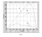
- FIG. 3 is a schematic view of a power output of a PV component with a solar cell sheltered.
- a horizontal axis denotes an output voltage of the PV component
- a vertical axis denotes a power of the PV component.
- a curve 101 is a power output curve during normal working
- curves 102 and 103 are output curves when different positions are sheltered.
- the curve 101 during the normal working is capable of achieving an output power of about 590W at the time of outputting 60V;
- the curve 102 with shelter problem is only capable of achieving about 360W at 60V;
- the another curve 103 with shelter problem (a shelter position of which is different from that of the curve 102) is only capable of achieving about 80W.
- the energy conversion controller cannot work due to an excessively low output voltage of the PV component, so as to cause electric energy waste.
- the present invention is directed to a solar light power generation system, a control device, and a control method thereof, capable of realizing an electric energy output with a better performance.
- An embodiment of the present invention provides a solar light power generation system, where the system includes:
- An embodiment of the present invention provides a control device of a solar light power generation system, configured to control a solar cell array to output electric energy, where the device includes:
- An embodiment of the present invention provides a control method of a solar light power generation system, where the system includes:
- characteristics of electric energy output by the solar cell array are detected, the combination of series connection and/or parallel connection of the multiple branches of electric energy is adjusted dynamically according to the characteristics of the electric energy, and the energy converting unit performs energy converting, so that various cases occurring in the system can be addressed by dynamical adjustment of combination, so as to obtain output electric energy with a better performance.
- the embodiment of the present invention provides a solar light power generation system, which is configured to obtain an electric energy output with a better performance by adjusting combination of the output of the solar cell array dynamically; the system includes a solar cell array, a combination control unit, and an energy converting unit.
- the solar cell array is configured to output multiple branches of electric energy
- Each branch of output of the solar cell array is output by a plurality of PV components connected in series, or is output by a plurality of groups of PV components connected in series after parallel connection.
- an output voltage can be increased; by connecting the PV components in parallel, an output current can be increased; and during parallel connection, in order to guarantee a reliability of the performance, several types of PV components with the same characteristics need to be selected to be connected in parallel.
- the process that the combination control unit adjust combination of series connection and/or parallel connection of the multiple branches of electric energy dynamically according to the output characteristics, so as to output one or more branches of electric energy includes at least one of the following:
- the adjustment can be performed according to various application situations. For example, when the PV components are sheltered, one or more branches of PV components being sheltered are output as one branch; or when short circuit occurs, the short-circuited branch of electric energy is cut off; or in a case of faint light, multiple branches of electric energy are connected in series into one branch to be output, so that the solar light power generation system obtains the output electric energy with the better performance.
- series connection and/or parallel connection means series connection or parallel connection, or series connection and parallel connection.
- series connection and parallel connection means series connection or parallel connection, or series connection and parallel connection.
- series-parallel connection is also configured to denote series connection and/or parallel connection. If it is not specially illustrated, both of the two refer to the same meaning, and are not strictly distinguished.
- the combination control unit includes a detecting unit, a switch component, and a processing unit.
- the detecting unit is configured to receive the multiple branches of electric energy output by the solar cell array, and detect the characteristics of the multiple branches of electric energy, in which content to be detected includes voltage and current; and it is determined that whether the characteristics of each branch of electric energy are similar or whether a failure occurs through values of the voltage and the current.
- the switch component is configured to combine the series-parallel connection of the multiple branches of electric energy, in which the switch component specifically can include a plurality of switch units, and each switch unit can be such parts having switch characteristics as a Metal Oxide Semiconductor (MOS) tube, or an Insulated Gate Bipolar Transistor (IGBT) part, or a controllable relay.
- MOS Metal Oxide Semiconductor
- IGBT Insulated Gate Bipolar Transistor
- the processing unit is configured to control the switch component to adjust combination of series connection and/or parallel connection of the multiple branches of electric energy dynamically according to the output characteristics of the multiple branches of electric energy detected by the detecting unit, so as to output one or more branches of electric energy.
- a time interval by which the processing unit performs dynamic combination and adjustment should be smaller, so as to perform one time of adjustment every other 1 second or 2 seconds.
- the energy converting unit includes one or more converting modules, and each converting module includes one or more converting channels.
- symmetric design can be adopted, that is, conversion capabilities of the converting modules are the same; or asymmetric design can also be adopted, that is, a plurality of converting modules or converting channels having different capabilities is adopted, and electric energy to be converted is allocated in a fixed proportion according to a conversion capability of each converting module or converting channel. For example, more input electric energy is allocated to a module or channel with a strong conversion capability, and less input electric energy is allocated to a module or channel with a weak conversion capability. Through allocation in a proportion, a load borne by each converting module or converting channel may not be excessively large or small, so that the system load is more balanced.
- one or more converting modules or converting channels without the necessity for participating conversion are switched off
- the electric energy to be converted can be connected to the small module, and the module or channel without the necessity for participating the conversion is switched off (or sleeps), so as to reduce power consumption of the system.
- the combination control unit detects the characteristics of the multiple branches of electric energy output by the solar cell array, enables multiple branches of electric energy having similar characteristics to be connected in parallel as one branch to be output according to the characteristics of the multiple branches of electric energy, and cuts off the electric energy with a failure, so that an influence caused by problematic electric energy on the entire electric energy can be avoided.
- multiple branches of electric energy can be further connected in series, so that the solar light power generation system according to the embodiment of the present invention can also output a voltage required by the system under such conditions as faint light, so as to increase a light energy utilization.
- the energy converting unit designs the energy conversion module or converting channel in a symmetric or asymmetric manner.
- the electric energy to be converted is less, one or more converting modules or converting channels without the necessity for participating conversion are switched off, and the power consumption of the system can be reduced.
- the solar light power generation system includes a solar cell array 41, a combination control unit 42, and an energy converting unit 43.
- the solar cell array 41 outputs M branches of electric energy to the combination control unit, after dynamically combining and controlling the M branches of electric energy, the combination control unit outputs N branches of electric energy to the energy converting unit, and after performing energy conversion, the energy converting unit outputs the electric energy to a power-consuming unit.
- M generally is larger than N.
- M generally is larger than 4, while N generally is 2 or 3.
- the solar light power generation system includes a solar cell array 41.
- the solar cell array 41 is configured to output one or more branches of electric energy.
- the most basic unit in the solar cell array is a solar cell, and the solar cell is made of a material having a photovoltaic effect, and can convert light energy into electric energy. Because electric energy output by a single solar cell is smaller, in order to satisfy a large output electric energy demand, a plurality of solar cells needs to be connected in series to form a PV component (or referred to as a solar cell component). Meanwhile, in order to achieve a more electric energy output, a plurality of PV components can be connected in series to increase a single-branch output voltage; and multiple branches of PV components (each branch has one PV component or a plurality of PV components connected in series) are connected in parallel to increase an output current.
- output voltages of branches can be the same or different.
- a first branch two PV components are connected in series, so as to output a voltage of 96V (each PV component outputs 48V), and in a second branch, three PV components are connected in series, so as to output a voltage of 144V.
- the output current can be increased by connecting the first branch in parallel with a branch of PV components with an output voltage of 96V.
- the solar cell array generally adopts PV components with the same specification, so that if the first branch needs to increase the output current, it can be realized by connecting the first branch in parallel with one branch being completely the same as itself.
- an output rated value (such as 48 V) of each PV component is an output in a specific lighting case, which does not represent that the output is always 48V in any lighting case. For example, when it is cloudy and rainy, early in the morning, or nightfall with weaker lighting, the value is not achieved, while at a summer noon with sufficient lighting, the output is above the value.
- an output voltage of a PV component is one dynamically changing value, but as long as the voltage falls within a range (such as 90V to 110V) required by the backend energy converting unit, energy conversion can be performed on the output electric energy, and then the output electric energy is output.
- the solar light power generation system according to the embodiment of the present invention further includes a combination control unit 42.
- the combination control unit 42 is configured to receive the multiple branches of electric energy output by the solar cell array, detect output characteristics of the multiple branches of electric energy, and adjust combination of series connection and/or parallel connection of the multiple branches of electric energy dynamically according to the output characteristics, so as to output one or more branches of electric energy.
- the combination control unit includes a switch module 421, a detecting unit 422, and a processing unit 423.
- the switch module 421 is formed by a plurality of switch units, and each switch unit is formed by a component having switch characteristics, such as an MOS tube, an IGBT component, or a controllable relay.
- the component includes one control end, which can be configured to control whether the component is on or off, so as to realize an effect being similar to the effect of one switch.
- a suitable switch part can be selected according to performance parameters of the system, or a design demand of the system is satisfied by combining a driving circuit.
- FIG. 5 is a schematic view of combining the series-parallel connections of the input electric energy by utilizing a plurality of switch units.
- a switch unit K3 is configured to determine whether the first branch and the second branch are connected.
- K1, K2, K4, and K5 are configured to determine whether the first branch and the second branch are output to corresponding output ends (Pout1 and Pout2), and each switch unit receives a control signal from the processing unit, so as to determine whether to switch on or switch off.
- FIG. 5A denotes a schematic view in which the first branch and the second branch are connected in series and are output from the Pout1 end.
- K3 and K4 are switched off through control of a control signal, the rest switches are switched on, and the first branch and the second branch can be connected in series, and then are output from the Pout1 end.
- FIG. 5B denotes a schematic view in which the first branch and the second branch are connected in parallel and are output from the Pout2 end.
- K1 and K4 are switched off through control of a control signal, the rest switches are switched on, and the first branch and the second branch can be connected in parallel, and then are output from the Pout1 end.
- the detecting unit 422 is configured to receive the multiple branches of electric energy output by the solar cell array, and detect output characteristics of branches of electric energy, such as detect whether the characteristics of the branches are similar, whether the branches are open-circuited, and whether the branches are short-circuited by detecting a voltage and a current.
- the processing unit 423 is configured to obtain the output characteristics of the branches of electric energy output by the detecting unit, and adjust combination of series connection and/or parallel connection of the multiple branches of electric energy dynamically according to the output characteristics of the multiple branches of electric energy detected by the detecting unit, so as to output one or more branches of electric energy. In order to better make a response to a state occurring in the system, the adjustment is performed dynamically in real time.
- the processing unit obtains the output characteristics of the branches of electric energy, determines a state which the solar cell array is in (such as performances of certain branches are reduced, or a failure occurs in several branches), adjust combination of series connection and/or parallel connection of the multiple branches of electric energy dynamically according to the state.
- the processing unit 423 can be realized by adopting a chip or hardware circuit having a processing function, such control chips as a Central Processing Unit (CPU), a Micro Controller Unit (MCU), and a Digital Signal Processor (DSP) or a hardware circuit having a similar function.
- control chips such as a Central Processing Unit (CPU), a Micro Controller Unit (MCU), and a Digital Signal Processor (DSP) or a hardware circuit having a similar function.
- the detecting unit 422 and the processing unit 423 are not strictly distinguished. In an actual application procedure, two units can use the same processing chip, such as, commonly use the same CPU chip. Some pins of the chip are used as an input of the detecting unit, while some other pins are used as an output of the processing unit.
- the processing chip when configured to perform detection and control, because the chip generally adopts a digital level (a voltage thereof is smaller, such as 3V to 5V) and is incompatible with an output level (a voltage thereof is larger, such as dozens of volts to hundreds of volts) of the solar cell array, the output level of the solar cell array needs to be converted into a level with which the processing chip is capable of being compatible through a relevant processing circuit, such as an amplitude limitation conditioning circuit (such as resistance drop-voltage). Design of the processing circuits is a technology well known by persons skilled in the art, and is not recited any more here.
- the processing unit 423 adjusts combination of series connection and/or parallel connection through control switch units. Specifically, the control end of the control switch unit is controlled to get characteristics of "on” or “off'; then the branch of electric energy is enable to output or cut off, or the connection relationships of the series-parallel connection are combined.
- FIG. 6A a left drawing is a schematic view during normal working, in which arrows denoted by digitals 1 to 6 denote the multiple branches of electric energy output by the solar cell array, and arrows denoted by letters A and B denote multiple branches of electric energy output to the energy converting unit after the combination control unit adjusts combination of series connection and/or parallel connection of multiple branches of electric energy dynamically
- the combination control unit connects a first branch, a second branch, and a third branch of input electric energy in parallel into one branch to be output to the energy converting unit, and connects a fourth branch, a fifth branch, and a sixth branch of input electric energy in parallel into one branch to be output to the energy converting unit.
- PV components in the second branch and the fourth branch are sheltered (such as, are sheltered by leaves, stones, animal excrement, and animal corpses), output characteristics of the branches are changed (for example, voltage and current values are reduced).
- output electric energy of the branches needs to be adjusted, and several branches of output electric energy with similar characteristics are output as one branch.
- the second branch and the fourth branch are sheltered, the second branch and the fourth branch are connected in parallel as one branch to be output; and the first branch, the third branch, the fifth branch, and the sixth branch are connected in parallel as one branch to be output.
- the second branch and the fourth branch are in a case that PV components are sheltered, and have similar characteristics of the electric energy; and the first branch, the third branch, the fifth branch, and the sixth branch are all in a normal working state, and have similar characteristics of the electric energy.
- Similar mentioned here can be understood as similar within a certain error.
- 100V can be considered to be similar to 98V, 95V, and 102V; or within another error range, 100V is considered to be similar to 90V and 110V.
- the electric energy with similar characteristics is connected in parallel as one branch to be output, so as to reduce a power loss due to parallel connection of tributaries with dissimilar characteristics.
- the failure mentioned here includes such cases as short circuit, open circuit, and a seriously insufficient voltage or current.
- a failure occurs in a PV component
- output, stability, and security of the entire system are all influenced.
- it is necessary to detect whether a failure occurs for each branch of electric energy in real time. If an abnormal case is detected, such abnormal cases as an excessively large current or excessively small voltage, the branch of electric energy needs to be cut off from the combination control unit, thereby avoiding the influence on the entire system.
- a short-circuit protection circuit can be further set on hardware, thereby avoiding the influence on the entire system.
- a left drawing is a schematic view during normal working of the system
- a right drawing is a schematic view that when a failure occurs in the fifth branch, the fifth branch is disconnected from the combination control unit.
- the control unit when finding out that the output electric energy is failed, may notify relevant maintenance personnel of failure information in various communication manners (including wired communication or wireless communication), so that after obtaining the failure information, the maintenance personnel is capable of repairing or replacing a failed equipment.
- Sending the failure information likewise can also be applied in a case that a PV component is sheltered, and the maintenance personnel are notified of clearing relevant shelter objects by sending the failure information.
- the case is generally applied in a faint light case when it is cloudy, rainy, early in the morning, or nightfall with relatively weaker sunlight.
- a single branch of PV components cannot output a required voltage or current, while if the backend energy converting unit needs to normally work, an input voltage thereof must achieve a certain value.
- the energy converting unit cannot normally work, that is, converts light energy into electric energy, so as to cause energy waste.
- several branches of PV components can be connected in series, so as to increase the output voltage, so that the energy converting unit can normally work.
- a left drawing is a schematic view during normal working of the system
- a right drawing is a schematic view in which the input multiple branches of electric energy are connected in series during faint light, so as to increase the output voltage.
- multiple branches of electric energy are output as one branch can not only be applied in the faint light case, and in another case that the voltage characteristics need to be changed, multiple branches of electric energy is also connected in series as one branch to be output, so as to increase an output voltage.
- the characteristics of the multiple branches of electric energy output by the solar cell array are detected in real time, and various dynamic adjustment manners such as combining multiple branches of electric energy with similar characteristics, cutting off output electric energy with a failure, and series-parallel connecting multiple branches of output electric energy (which can be one or a combination of several types) are performed according to the characteristics of the electric energy, so that the system is always running in a good working state.
- the solar light power generation system further includes an energy converting unit 43.
- the energy converting unit 43 is configured to receive the one or more branches of electric energy output by the combination control unit, perform energy converting, and output the converted electric energy.
- the combination control unit adjusts combination of the output of the solar cell array, so as to output one or more branches of electric energy.
- the combination control unit In a normal working case, or in a shelter case, the combination control unit generally outputs multiple branches of electric energy; and in a faint light case that an output voltage and a current need to be increased, multiple branches can be connected in series or in parallel into one branch to be output.
- the energy conversion includes such processing as DC-DC, DC-AC, and DC voltage stabilizing.
- conversion as DC-DC or DC-AC is performed, not only can a high voltage be converted into a low voltage, but also a low voltage can be converted into a high voltage.
- each branch can further perform the energy conversion in an Interleave manner, so as to increase an efficiency of the energy conversion.
- the performing the energy conversion in the Interleave manner is a technology well known by persons skilled in the art, and is not recited any more here.
- the energy converting unit includes one or more converting modules, and each converting module includes one or more converting channels.
- the specific implementation manner generally can include the following several types.
- the plurality of converting modules performs the energy conversion.
- FIG. 7A is a schematic view in which the energy conversion is performed by adopting a plurality of single modules, and each module only has one converting channel.
- Power conversion capabilities of the plurality of converting modules can be the same, or can also be different.
- an asymmetric converting module configuration can be adopted, that is, a configuration method of combining large power converting modules and small power converting modules is adopted: a large power channel output after the combining of the combination control unit is connected with a large power converting module; a small power channel output after the combining of the combination control unit is connected with a small power converting module; and in certain application cases (such as a faint light case), it can be that, the large power converting module is not used, while only the small power converting module is used.
- a power consumed by the small power converting module itself is smaller than a power consumed by the large power converting module, so that when the large power converting module is switched off (or sleeps) while only the small power converting module is used, the
- One converting module performs the energy conversion.
- FIG. 7B is a schematic view of adopting one converting module to perform the energy conversion.
- the converting module integrally includes a plurality of energy converting channels, capability grades of performing the energy conversion by energy channels can be the same or can also be different, and a channel with a large channel energy conversion capability is connected with the large power channel output after the combining of the combination control unit.
- a channel with a small channel energy conversion capability is connected with the small power channel output after the combining of the combination control unit.
- a power consumed by a converting channel with a small capability grade is small, so that, in certain application cases, it can be that, a converting channel with a large capability grade is not used, while only a converting channel with a small grade is used, so as to reduce the power consumption of the system.
- the aforementioned two cases can be combined.
- two modules are adopted. One is a single module, and the other is a converting module with a plurality of converting channels.
- the embodiment of the present invention provides a solar light power generation system, which includes a solar cell array 81, a combination control unit 82, and an energy converting unit 83.
- the solar cell array 81 is formed by a plurality of series-parallel connection PV components.
- a structure of the PV component is introduced in the background of the invention, and is not recited any more here. If the plurality of PV components is connected in series, the output voltage can be increased; and if the plurality of PV components is connected in parallel, the output current can be increased.
- a single PV component (or a plurality of PV components after being connected in series) having similar voltage characteristics should be selected to be connected in parallel. If a difference between two branches of voltage characteristics connected in parallel with each other is larger, an entire circuit performance after parallel connection is reduced.
- the solar cell array 81 is formed by multiple branches of PV components after being connected in series.
- PV components 1-1 to 1-N1 denote a first branch
- PV components 2-1 to 2-N2 denote a second branch
- the rest several branches are denoted in a similar method.
- five branches of PV components connected in series are shown.
- the amount of PV components is not limited, and the amount of PV component output branches can be increased or reduced according to an application demand.
- the method that a positive line segment and a negative line segment are configured to denote output electric energy in FIG. 2 is changed into a method of denoting positive and negative with one line segment. It should be understood that, persons skilled in the art can correctly connect a practical circuit according to the denoting method.
- each PV component outputs a voltage of 20V, if a voltage of 100V needs to be output, five PV components can be connected in series; and if a voltage of 40 V needs to be output, only two PV components need to be connected in series.
- branches of PV components connected in series in branches are generally the same.
- FIG. 8 in the embodiments of the present invention, it is assumed that five branches of PV components connected in series are provided totally, and each branch of output is formed by PV components connected in series with the same type and the same amount.
- the first branch and the second branch are connected in parallel, and then are output.
- totally four branches of electric energy are finally output to the combination control unit, which are branches A, B, C, and D respectively.
- the branch A is obtained after the first branch and the second branch are connected in parallel, the branch B corresponds to the third branch, the branch C corresponds to the fourth branch, and the branch D corresponds to the fifth branch.
- the combination control unit 82 includes a detecting unit 821, a processing unit 822, and a plurality of switch units K1 to K11.
- the combination control unit receives four branches (branches A, B, C, and D) of electric energy output by the solar cell array, and outputs two branches (branches E and F) of electric energy to the energy converting unit after dynamically combining and controlling the four branches of electric energy.
- the input four branches of electric energy form one combining and switching network through the plurality of switch units K1 to K11, so that the multiple branches of electric energy are capable of forming various series-parallel connection combinations, so that the inputs of electric energy are dynamically adjusted.
- K1, K2, and K3 are configured to set whether two adjacent branches of input electric energy are connected in series, and K4 to K1 are configured to set whether each branch of input electric energy is input to a corresponding output end (E and F).
- each switch unit can be completed by adopting such parts having a switch effect as an MOS tube, an IGBT, and a relay.
- a left drawing is a schematic view of an MOS component, which includes a gate (G), a drain (D), and a source (S); and a right drawing is a schematic view in which the MOS component is equivalent into one switch.
- the MOS regards the gate (G) of the MOS tube as a control end, and regards the drain (D) and the source (S) as two signal ends, and the MOS tube is used as a switch part.
- the switch part needs to select a matched part according to system characteristics. Moreover, some additional circuits (such as a driving circuit and a protection circuit) can be further added to satisfy a performance required by the system.
- the processing unit combines and adjusts combination of the inputs of electric energy according to the detected result obtained by the detecting unit, which includes the following cases.
- branches C when the branch C is sheltered, in this way, its output characteristics are dissimilar to those of the branches A, B, and D during normal working (the voltage and the current are apparently reduced), and at this time, the branch C can be separately output as one branch; and electric energy of the rest several branches during normal working is output as another branch.
- states of switch units can be controlled as follows.
- K1, K2, K3, K5, K6, and K8 are switched on.
- K4, K7, K9, K10, and K11 are switched off.
- a finally formed equivalent circuit diagram is as shown in FIG. 9A , that is, the branches A, B, and D are connected in parallel and then connected to the branch E; and the branch C is separately connected to the branch F.
- the electric energy of similar performance is output as one branch, so as to reduce an influence on the entire system caused by a branch of electric energy with a worse performance.
- three branches of electric energy are totally provided currently, which output 100 W during normal working, and electric energy of 300 W can be output totally.
- an output of the entire system is influenced.
- the electric energy with shelter problem can be output separately as another branch, while two original branches are still output as one branch.
- the branch C when the branch C is failed and needs to be disconnected, all the switches associated with the branch C can be disconnected, such as in the embodiment of the present invention, the branch C is disconnected.
- the branches A and B are connected in parallel and then connected to the branch E, the branch D is separately connected to the branch F, and states of switch units can be controlled as follows.
- K1, K2, K3, K5, K6, K7, K10, and K11 are switched on.
- K4, K8, and K9 are switched off.
- a finally formed equivalent circuit diagram is as shown in FIG. 9B , that is, the branch C is disconnected, the branches A and B are connected in parallel and then connected to the branch E, and the branch D is separately connected to the branch F.
- the processing unit can further notify a console or maintenance personnel of updating equipment through a communication interface 723 (including wired and wireless manners); meanwhile, the processing unit can also receive an instruction from the console or the maintenance personnel, so as to combine and adjust various input electric energy.
- branches can be connected in series to be output, so as to increase the output voltage.
- FIG. 9C is a schematic view in which the branches A, B, C, and D are connected in series to be output. At this time, switch states of switch units controlled by the processing unit are as follows.
- K4, K5, K6, K7, K8, K10, and K11 are switched on.
- K1, K2, K3, and K9 are switched off.
- the switch states of the switch units are set, so that the branches A, B, C, and D can be connected in series to be output, and an output voltage is equal to a sum of voltages of branches.
- one branch of electric energy including a positive pole and a negative pole
- one line segment so that the positive and negative poles of a power supply are not denoted.
- polarity it can also be considered that, after K9 is switched on and K7 is switched off, output is performed. Referring to FIG. 10 , a case of the aforementioned two different polarities can be denoted.
- connection and setting of the positive and negative poles of the power supply fall within a technology well known by persons skilled in the art, and are not recited any more here.
- FIG. 9D is a schematic view in which the branches A, B, C, and D are all connected in parallel to be output. At this time, switch states of switch units controlled by the processing unit are as follows.
- K1, K2, K3, K5, K8, K10, and K11 are switched on.
- the switch states of the switch units are set, and all input electric energy is connected in parallel and output to the branch E, so that a working current input to the branch E can be increased.
- branches capable of satisfying a system parameter requirement are selected to be connected in series or in parallel according to the system parameter requirement. For example, only two branches or three branches are connected in series or in parallel.
- the detection and the adjustment are performed in real time, such as once every other 1 second or 2 seconds.
- the characteristics of the multiple branches of electric energy output by the solar cell array are detected in real time, and multiple branches of electric energy with similar characteristics are combined and output electric energy with a failure is cut off according to the electric energy characteristics, so that an influence on the entire system due to problems that a certain branch is sheltered or is failed can be avoided.
- Multiple branches of electric energy are connected in series or in parallel into one branch to be output, so that electric energy required by the energy converting unit is also capable of being output in insufficient lighting situations as when it is cloudy, rainy, early in the morning, or nightfall, so as to increase an light energy utilizing efficiency, and increase an electric energy yield.
- the solar light power generation system according to the embodiment of the present invention further includes an energy converting unit 73.
- the energy converting unit 73 is configured to receive one or more branches of electric energy of the combination control unit, perform energy converting, and output the converted electric energy.
- a converting module of the energy converting unit completes DC-DC and DC-AC energy conversion by adopt various existing or unknown energy conversion modules, and outputs the converted electric energy to a power-consuming unit.
- the energy converting unit can realize the energy conversion through a plurality of converting modules or a converting module having a plurality of converting channels, or can also realize the energy conversion by combining the two manners.
- two converting modules are adopted to realize the energy conversion, and conversion capabilities of the two converting modules are not the same, but a conversion capability of one converting module is preferably larger than the largest output of the solar cell array. In this way, even when the other converting module does not work, energy conversion of electric energy output by the solar cell array is also capable of be realized.
- the two modules are generally not in a full load working state, but electric energy to be converted is allocated in a fixed proportion.
- a converting module with a strong conversion capability is connected with electric energy with a large power output by the combination control unit (occupying a large proportion of the electric energy to be converted), and a converting module with a weak conversion capability is connected with electric energy with a small power output by the combination control unit (occupying a small proportion of the electric energy to be converted), so that the system load can be more balanced.
- the largest conversion power of a first converting module is 2000 W
- the largest conversion power of a second converting module is 1000 W
- the electric energy to be converted is allocated to the two modules in a proportion of 7:3. It is assumed that, during normal working of the system, the solar cell array is capable of outputting 1800 W, the first converting module converts 7/10 of 1800W, and the second converting module converts 3/10 of 1800 W.
- a branch thereof can be switched off (or sleep), so as to reduce the power consumption of the system.
- the electric energy to be converted is only 800 W
- the first converting module can be switched off, while only the second converting module works
- the second converting module can be switched off, while only the converting module 1 is configured to work (in this case, the two converting modules can also work together).
- the embodiment of the present invention provides a control device of a solar light power generation system.
- the control device includes a detecting unit 111, a switch module 112, and a combination processing unit 113.
- the detecting unit 111 is configured to receive multiple branches of electric energy output by a solar cell array, and detect characteristics of the multiple branches of electric energy.
- the switch module 112 is configured to combine the series-parallel connections of multiple branches of electric energy.
- the combination processing unit 113 is configured to control the switch module to adjust combination of series connection and/or parallel connection of the multiple branches of electric energy dynamically according to the characteristics of the multiple branches of electric energy detected by the detecting unit, so as to output one or more branches of electric energy.
- the combination processing unit 113 adjusts combination of the series connection and/or parallel connection of the multiple branches of electric energy dynamically, so as to output one or more branches of electric energy, at least one of the following exists.
- multiple branches of electric energy are connected in series into one branch to be output.
- the characteristics of the multiple branches of electric energy detected by the detecting unit include a voltage and a current of electric energy. Voltages or currents within a certain error range can be considered to be similar. If a voltage of a certain branch of electric energy is seriously reduced, the branch of electric energy can be considered to be failed.
- the detecting unit detects the characteristics of the electric energy in real time, so that a response to the failure can be made as fast as possible.
- the combination processing unit can obtain the characteristics of the branches of electric energy actively, or obtain the characteristics by receiving a report of the detecting unit.
- the switch module 112 includes a plurality of switch units 114, configured to combine the multiple branches of electric energy through series-parallel connection, so that the multiple branches of electric energy can be capable of increasing an output voltage through series connection, and also be capable of increasing an output current through parallel connection.
- a switch unit can adopt such parts having switch characteristics as an MOS tube, an IGBT part, and a controllable relay, details can refer to the description of the switch unit in the embodiment, and are not recited any more here.
- the combination processing unit obtains the characteristics of the multiple branches of electric energy detected by the detecting unit, and adjusts combination of series connection and/or parallel connection of the multiple branches of electric energy dynamically specifically by controlling on or off of a plurality of switch units, which specifically may include at least one of the following application situation.
- a branch or several branches being sheltered cause a performance of an entire branch or even the entire system to be reduced, so that the combination processing unit can connect one or more sheltered branches of electric energy in parallel into one branch to be output, and the rest electric energy in normal working is connected in parallel as another branch to be output.
- the combination processing unit can control a switch unit to isolate electric energy with a failure from the output, so as to avoid an influence on the performance of the entire system.
- the combination processing unit can connect the multiple branches of electric energy in series, so as to output a required voltage.
- the dynamic adjustment is performed in real time, specific interval time can be set smaller (such as 1 second or 2 seconds), so as to timely make a response to a state occurring in the system.
- the dynamic adjustment is performed in one of or several cases, so that the entire system can avoid a case of reducing the performance of the entire system due to a problem occurring for a certain branch or several branches of output electric energy.
- the multiple branches of electric energy are connected in series to be output, so as to increase the output voltage and satisfy a demand of the system on the voltage.
- the solar light power generation system according to the embodiment of the present invention can exist in a single equipment form, or in order to be compatible with existing equipment, the solar light power generation system can also be designed to be located in a line collecting box of an existing solar light power generation system.
- the embodiment of the present invention provides a control method of a solar light power generation system.
- the control method includes the following steps.
- S121 receiving multiple branches of electric energy output by a solar cell array, and detecting characteristics of the multiple branches of electric energy;
- S122 adjusting combination of series connection and/or parallel connection of the multiple branches of electric energy dynamically according to the detected characteristics of the multiple branches of electric energy, so as to output one or more branches of electric energy.
- the process that adjusting combination of series connection and/or parallel connection of the multiple branches of electric energy dynamically according to the detected characteristics of the multiple branches of electric energy, so as to output one or more branches of electric energy includes at least one of the following:
- the detecting the characteristics of the multiple branches of electric energy includes detecting a voltage and a current of the electric energy. Voltages or currents within a certain error range can be considered to be similar. If a voltage of a certain branch of electric energy is seriously reduced, the branch of electric energy can be considered to be failed. Meanwhile, the characteristics of the electric energy are detected in real time, so that a response to the failure can be made as fast as possible.
- the combination of series connection and/or parallel connection of the multiple branches of electric energy are dynamically adjusted by switching a plurality of switch units in a switch module, the plurality of switch units in the plurality of switch module is configured to combine outputs of the solar cell array through series-parallel connection, so that the multiple branches of electric energy can be capable of increasing an output voltage through series connection, and also be capable of increasing an output current through parallel connection.
- a switch unit can adopt such parts having switch characteristics as an MOS tube, an IGBT part, and a controllable relay.
- the combination of series connection and/or parallel connection of the multiple branches of electric energy are dynamically adjusted by switching a plurality of switch units in a switch module "on” or "off", which includes at least one of the following application situations.
- a branch or several branches being sheltered cause a performance of an entire branch or even the entire system to be reduced, so that several branches of sheltered electric energy can be connected in parallel into one branch to be output, and the rest electric energy in normal working is connected in parallel as another branch to be output.
- a switch unit can be controlled to isolate electric energy with a failure from the output, so as to avoid an influence on the performance of the entire system.
- the multiple branches of electric energy can be connected in series, so as to output a required voltage.
- various characteristics of the electric energy are obtained in real time, and the dynamic adjustment is performed for one or several cases timely, so that the entire system can avoid a case of reducing the performance of the entire system due to a problem occurring for a certain branch or several branches of output electric energy.
- the multiple branches of electric energy are connected in series to be output, so as to increase the output voltage and satisfy a demand of the system on the voltage.
- the control method can be realized based on the system or equipment in the embodiment, or can also be realized by adopting a hardware entity having similar functions.
- the program may be stored in a computer readable storage medium.
- the storage medium may be a magnetic disk, an optical disk, a read-only memory (ROM), or a random access memory (RAM).
Landscapes
- Engineering & Computer Science (AREA)
- Power Engineering (AREA)
- Control Of Electrical Variables (AREA)
- Direct Current Feeding And Distribution (AREA)
- Supply And Distribution Of Alternating Current (AREA)
- Photovoltaic Devices (AREA)
Applications Claiming Priority (1)
| Application Number | Priority Date | Filing Date | Title |
|---|---|---|---|
| CN2010101423378A CN101800498B (zh) | 2010-04-01 | 2010-04-01 | 太阳能光发电系统、控制装置及控制方法 |
Publications (2)
| Publication Number | Publication Date |
|---|---|
| EP2372487A2 true EP2372487A2 (de) | 2011-10-05 |
| EP2372487A3 EP2372487A3 (de) | 2013-01-09 |
Family
ID=42596034
Family Applications (1)
| Application Number | Title | Priority Date | Filing Date |
|---|---|---|---|
| EP20100197387 Withdrawn EP2372487A3 (de) | 2010-04-01 | 2010-12-30 | System zur Erzeugung von Solarenergie, Steuerungsvorrichtung und Steuerungsverfahren dafür |
Country Status (4)
| Country | Link |
|---|---|
| US (1) | US20110241431A1 (de) |
| EP (1) | EP2372487A3 (de) |
| CN (1) | CN101800498B (de) |
| WO (1) | WO2011120311A1 (de) |
Cited By (3)
| Publication number | Priority date | Publication date | Assignee | Title |
|---|---|---|---|---|
| WO2013019779A3 (en) * | 2011-08-04 | 2013-11-14 | Eaton Corporation | System and method for increasing voltage in a photovoltaic inverter |
| EP2770539A1 (de) * | 2013-02-20 | 2014-08-27 | Total Marketing Services | Elektronisches Verwaltungssystem für Stromerzeugungszellen, Stromerzeugungssystem und Verfahren zur elektronischen Verwaltung des Energieflusses |
| EP3410552A1 (de) * | 2017-05-30 | 2018-12-05 | Solaredge Technologies Ltd. | Routing-leistung in einem stromversorgungssystem |
Families Citing this family (32)
| Publication number | Priority date | Publication date | Assignee | Title |
|---|---|---|---|---|
| US8748727B2 (en) | 2008-01-18 | 2014-06-10 | Tenksolar, Inc. | Flat-plate photovoltaic module |
| US8212139B2 (en) | 2008-01-18 | 2012-07-03 | Tenksolar, Inc. | Thin-film photovoltaic module |
| US8933320B2 (en) | 2008-01-18 | 2015-01-13 | Tenksolar, Inc. | Redundant electrical architecture for photovoltaic modules |
| IN2012DN00387A (de) | 2009-06-15 | 2015-08-21 | Tenksolar Inc | |
| US9773933B2 (en) | 2010-02-23 | 2017-09-26 | Tenksolar, Inc. | Space and energy efficient photovoltaic array |
| CN101800498B (zh) * | 2010-04-01 | 2013-12-04 | 华为技术有限公司 | 太阳能光发电系统、控制装置及控制方法 |
| US9299861B2 (en) | 2010-06-15 | 2016-03-29 | Tenksolar, Inc. | Cell-to-grid redundandt photovoltaic system |
| CA2849356A1 (en) * | 2010-09-23 | 2012-03-29 | Hybridyne Power Electronics Inc. | A method and system for optimizing power generated from a photovoltaic system |
| CN102170223B (zh) * | 2010-12-17 | 2014-04-02 | 中国石油集团长城钻探工程有限公司 | 成像测井系统直流电源 |
| US8669674B2 (en) * | 2010-12-17 | 2014-03-11 | Nxp B.V. | Power supply circuit with shared functionality and method for operating the power supply circuit |
| CN103999354B (zh) * | 2011-10-31 | 2017-03-01 | 腾克太阳能公司 | 电池到电网的冗余光伏系统 |
| KR101942095B1 (ko) * | 2012-04-17 | 2019-01-25 | 한국전자통신연구원 | 에너지 하베스팅 시스템에서의 전력 변환 장치 및 그 방법 |
| CN102931684A (zh) * | 2012-11-09 | 2013-02-13 | 东华大学 | 一种光伏交直流智能配电箱 |
| KR20140142111A (ko) * | 2013-06-03 | 2014-12-11 | 삼성전자주식회사 | 전원 공급 장치 및 이를 포함하는 전자 장치 |
| EP2975757A1 (de) * | 2014-07-14 | 2016-01-20 | ABB Technology AG | Transformatorloser dreiphasiger DC/AC Wechselrichter |
| CN105939022B (zh) * | 2016-01-26 | 2018-08-24 | 姜宪明 | 一种用于光伏发电系统的并网离网兼容切换系统 |
| CN105811875A (zh) * | 2016-03-30 | 2016-07-27 | 西安理工大学 | 一种提升光伏发电系统发电量的光伏阵列变结构控制方法 |
| US10554050B2 (en) | 2017-04-21 | 2020-02-04 | Futurewei Technologies, Inc. | Method and apparatus for controlling solar power systems |
| CN107846038B (zh) * | 2017-09-15 | 2019-12-31 | 珠海格力电器股份有限公司 | 一种光伏接线装置、功率优化系统及方法 |
| CN110581589A (zh) * | 2018-06-07 | 2019-12-17 | 北京汉能光伏投资有限公司 | 太阳能单元电路、太阳能装置、连接器和太阳能系统 |
| CN110119536B (zh) * | 2019-04-12 | 2022-11-11 | 北京空间飞行器总体设计部 | 一种深空探测器太阳电池系统设计方法 |
| US20210021139A1 (en) * | 2019-07-19 | 2021-01-21 | Michael E. Windsor | Multi-voltage portable power system |
| CN110336460B (zh) * | 2019-07-28 | 2021-11-09 | 电子科技大学 | 一种能源芯片及其封装制备方法与应用 |
| CN110729769A (zh) * | 2019-10-11 | 2020-01-24 | 大唐水电科学技术研究院有限公司 | 一种基于光伏与水电联合发电的功率分配方法 |
| CN110868153B (zh) * | 2019-11-29 | 2021-07-30 | 上海科世达-华阳汽车电器有限公司 | 光伏系统中逆变器投入启用方法、装置、设备及存储介质 |
| CN111446738A (zh) * | 2020-04-28 | 2020-07-24 | 科华恒盛股份有限公司 | 光伏逆变系统及其控制方法 |
| CN113497460B (zh) * | 2021-09-08 | 2021-11-30 | 西南交通大学 | 一种接入牵引变电所的分布式发电系统及控制方法 |
| CN114498608A (zh) * | 2022-03-16 | 2022-05-13 | 青岛海信日立空调系统有限公司 | 发电电路及其控制方法、空调 |
| CN116131320A (zh) * | 2022-12-05 | 2023-05-16 | 珠海格力电器股份有限公司 | 光伏发电系统及其控制方法、空调系统 |
| CN115693963A (zh) * | 2023-01-04 | 2023-02-03 | 安徽大恒新能源技术有限公司 | 一种智能组件 |
| CN118449281B (zh) * | 2024-07-02 | 2024-10-11 | 锦浪科技股份有限公司 | 一种发电保护系统 |
| CN223024139U (zh) * | 2024-07-31 | 2025-06-24 | 比亚迪股份有限公司 | 储能电路、储能系统及电子设备 |
Family Cites Families (17)
| Publication number | Priority date | Publication date | Assignee | Title |
|---|---|---|---|---|
| CN1016127B (zh) * | 1987-12-04 | 1992-04-01 | 越良 | 波形重组合电源 |
| JPH07177652A (ja) * | 1993-12-17 | 1995-07-14 | Canon Inc | 太陽光発電システムおよび太陽光発電システムの保護方式 |
| JPH0937490A (ja) * | 1995-07-20 | 1997-02-07 | Nissin Electric Co Ltd | 太陽電池システム及び太陽光発電システム |
| JP3568023B2 (ja) * | 1998-05-07 | 2004-09-22 | シャープ株式会社 | 太陽光発電用電力変換装置 |
| CA2463135C (en) * | 2001-10-11 | 2014-10-07 | Denovo Research, Llc | Dynamic battery array controllable to provide individual electrical power busses for different electrical loads |
| US6826064B2 (en) * | 2002-06-03 | 2004-11-30 | Winbond Electronics Corporation | Stable voltage converter with multiple pulse width modulated channels |
| US6800964B2 (en) * | 2002-06-10 | 2004-10-05 | Bernhard Beck | Plural configurable DC sources to provide optimal power to plural configurable inverters |
| CN1929235A (zh) * | 2005-09-09 | 2007-03-14 | 郝万福 | 智能电容式太阳能电源 |
| CN1933276A (zh) * | 2005-09-14 | 2007-03-21 | 郝万福 | 智能电容式向日太阳能电源 |
| ITPD20060382A1 (it) * | 2006-10-13 | 2008-04-14 | Elettronica Santerno S P A | Inverter solare e impianto di conversione di energia solare in energia elettrica |
| CN100403620C (zh) * | 2006-11-30 | 2008-07-16 | 北京恒基伟业投资发展有限公司 | 一种利用光伏电池自适应串并联充电的方法和装置 |
| US7772716B2 (en) * | 2007-03-27 | 2010-08-10 | Newdoll Enterprises Llc | Distributed maximum power point tracking system, structure and process |
| US20090079412A1 (en) * | 2007-09-24 | 2009-03-26 | Yao Hsien Kuo | Apparatus and method for controlling the output of a photovoltaic array |
| FR2923653B1 (fr) * | 2007-11-08 | 2009-11-27 | Harald Hauf | Procede de fonctionnement et dispositif de commande d'une installation energetique a modules photovoltaiques. |
| EP2200172A4 (de) * | 2008-03-04 | 2018-03-07 | Asahi Kasei EMD Corporation | Motorsteuerungsschaltung, motorsystem und motorsteuerungsverfahren |
| US20100084924A1 (en) * | 2008-10-07 | 2010-04-08 | Sunlight Photonics Inc. | Apparatus and method for producing ac power |
| CN101800498B (zh) * | 2010-04-01 | 2013-12-04 | 华为技术有限公司 | 太阳能光发电系统、控制装置及控制方法 |
-
2010
- 2010-04-01 CN CN2010101423378A patent/CN101800498B/zh not_active Expired - Fee Related
- 2010-12-14 WO PCT/CN2010/079748 patent/WO2011120311A1/zh not_active Ceased
- 2010-12-30 EP EP20100197387 patent/EP2372487A3/de not_active Withdrawn
- 2010-12-30 US US12/982,182 patent/US20110241431A1/en not_active Abandoned
Non-Patent Citations (1)
| Title |
|---|
| None |
Cited By (10)
| Publication number | Priority date | Publication date | Assignee | Title |
|---|---|---|---|---|
| WO2013019779A3 (en) * | 2011-08-04 | 2013-11-14 | Eaton Corporation | System and method for increasing voltage in a photovoltaic inverter |
| EP2770539A1 (de) * | 2013-02-20 | 2014-08-27 | Total Marketing Services | Elektronisches Verwaltungssystem für Stromerzeugungszellen, Stromerzeugungssystem und Verfahren zur elektronischen Verwaltung des Energieflusses |
| WO2014128202A1 (en) * | 2013-02-20 | 2014-08-28 | Total Marketing Services | Electronic management system for electricity generating cells, electricity generating system and method for electronically managing energy flow |
| CN105264671A (zh) * | 2013-02-20 | 2016-01-20 | 道达尔销售服务公司 | 用于发电电池的电子管理系统、发电系统和用于电子地管理能量流的方法 |
| US9627893B2 (en) | 2013-02-20 | 2017-04-18 | Total Marketing Services | Electronic management system for electricity generating cells, electricity generating system and method for electronically managing energy flow |
| CN105264671B (zh) * | 2013-02-20 | 2017-10-24 | 道达尔销售服务公司 | 用于发电电池的电子管理系统、发电系统和用于电子地管理能量流的方法 |
| EP3410552A1 (de) * | 2017-05-30 | 2018-12-05 | Solaredge Technologies Ltd. | Routing-leistung in einem stromversorgungssystem |
| US11171491B2 (en) | 2017-05-30 | 2021-11-09 | Solaredge Technologies Ltd. | Routing power in a power system |
| EP4117132A1 (de) * | 2017-05-30 | 2023-01-11 | Solaredge Technologies Ltd. | Routing-leistung in einem stromversorgungssystem |
| US11616361B2 (en) | 2017-05-30 | 2023-03-28 | Solaredge Technologies Ltd. | Routing power in a power system |
Also Published As
| Publication number | Publication date |
|---|---|
| WO2011120311A1 (zh) | 2011-10-06 |
| US20110241431A1 (en) | 2011-10-06 |
| CN101800498B (zh) | 2013-12-04 |
| EP2372487A3 (de) | 2013-01-09 |
| CN101800498A (zh) | 2010-08-11 |
Similar Documents
| Publication | Publication Date | Title |
|---|---|---|
| EP2372487A2 (de) | System zur Erzeugung von Solarenergie, Steuerungsvorrichtung und Steuerungsverfahren dafür | |
| US9583939B2 (en) | Optimizing solar power conversion | |
| EP3410551B1 (de) | System für miteinander verbundene elemente eines stromnetzes | |
| US8115340B2 (en) | System for controlling power from a photovoltaic array by selectively configurating connections between photovoltaic panels | |
| US9748772B2 (en) | Method of controlling a solar power plant, a power conversion system, a DC/AC inverter and a solar power plant | |
| CN101902051B (zh) | 一种用于太阳能电池板的高效能量转换装置,阵列及其应用方法 | |
| CN104953945B (zh) | 高效率的光伏发电系统以及发电方法 | |
| US9608438B2 (en) | Inverter system for photovoltaic power generation | |
| CN102624022A (zh) | 一种光伏并网发电系统及其直流母线电压控制方法 | |
| US20140333141A1 (en) | Photovoltaic (pv)-based ac module and solar systems therefrom | |
| CN104052391B (zh) | 光伏旁路和输出开关装置和方法 | |
| CN112868153A (zh) | 一种应用于光伏发电系统的变换器、方法及系统 | |
| US8358489B2 (en) | Smart photovoltaic panel and method for regulating power using same | |
| CN104660038A (zh) | 一种智能太阳能光伏组件电路及其控制/保护方法 | |
| CN108767842A (zh) | 一种光伏与电网互补的直流空调供电系统 | |
| CN104578171B (zh) | 一种直流光伏发电模块的控制方法 | |
| US20120187766A1 (en) | Device and Method For Improving The Performance Of An Inverter In A Photovoltaic System | |
| CN113544952A (zh) | 一种电源系统 | |
| CN105227128A (zh) | 一种新型光伏模块化多电平变换器及其控制方法 | |
| WO2021088491A1 (zh) | 一种光伏控制装置、方法及系统 | |
| KR101777230B1 (ko) | 태양광 발전을 위한 인버터 시스템 | |
| CN102159003A (zh) | 太阳能风能集成高智能控制方法及其系统 | |
| WO2021208141A1 (zh) | 一种电源系统 | |
| CN202488152U (zh) | 多路dc输入的光伏并网逆变器母线电压自适应控制装置 | |
| CN117613998A (zh) | 光伏并网系统及其运行方法 |
Legal Events
| Date | Code | Title | Description |
|---|---|---|---|
| PUAI | Public reference made under article 153(3) epc to a published international application that has entered the european phase |
Free format text: ORIGINAL CODE: 0009012 |
|
| AK | Designated contracting states |
Kind code of ref document: A2 Designated state(s): AL AT BE BG CH CY CZ DE DK EE ES FI FR GB GR HR HU IE IS IT LI LT LU LV MC MK MT NL NO PL PT RO RS SE SI SK SM TR |
|
| AX | Request for extension of the european patent |
Extension state: BA ME |
|
| PUAL | Search report despatched |
Free format text: ORIGINAL CODE: 0009013 |
|
| AK | Designated contracting states |
Kind code of ref document: A3 Designated state(s): AL AT BE BG CH CY CZ DE DK EE ES FI FR GB GR HR HU IE IS IT LI LT LU LV MC MK MT NL NO PL PT RO RS SE SI SK SM TR |
|
| AX | Request for extension of the european patent |
Extension state: BA ME |
|
| RIC1 | Information provided on ipc code assigned before grant |
Ipc: H02J 3/38 20060101ALI20121130BHEP Ipc: H02M 1/00 20070101AFI20121130BHEP |
|
| 17P | Request for examination filed |
Effective date: 20130425 |
|
| 17Q | First examination report despatched |
Effective date: 20140206 |
|
| STAA | Information on the status of an ep patent application or granted ep patent |
Free format text: STATUS: THE APPLICATION IS DEEMED TO BE WITHDRAWN |
|
| 18D | Application deemed to be withdrawn |
Effective date: 20140617 |