EP2372311A2 - Route display device, route display method, computer program product, and route display system - Google Patents
Route display device, route display method, computer program product, and route display system Download PDFInfo
- Publication number
- EP2372311A2 EP2372311A2 EP20110158667 EP11158667A EP2372311A2 EP 2372311 A2 EP2372311 A2 EP 2372311A2 EP 20110158667 EP20110158667 EP 20110158667 EP 11158667 A EP11158667 A EP 11158667A EP 2372311 A2 EP2372311 A2 EP 2372311A2
- Authority
- EP
- European Patent Office
- Prior art keywords
- route
- charging
- destination
- routes
- travel
- Prior art date
- Legal status (The legal status is an assumption and is not a legal conclusion. Google has not performed a legal analysis and makes no representation as to the accuracy of the status listed.)
- Withdrawn
Links
- 238000000034 method Methods 0.000 title claims description 20
- 238000004590 computer program Methods 0.000 title claims description 7
- 230000015654 memory Effects 0.000 claims description 2
- 238000004364 calculation method Methods 0.000 description 19
- 238000001514 detection method Methods 0.000 description 3
- 238000010586 diagram Methods 0.000 description 2
- 230000000694 effects Effects 0.000 description 2
- 238000005516 engineering process Methods 0.000 description 2
- 238000009825 accumulation Methods 0.000 description 1
- 238000002485 combustion reaction Methods 0.000 description 1
- 238000013500 data storage Methods 0.000 description 1
- 238000007599 discharging Methods 0.000 description 1
- 239000000446 fuel Substances 0.000 description 1
- 239000002828 fuel tank Substances 0.000 description 1
- 238000012986 modification Methods 0.000 description 1
- 230000004048 modification Effects 0.000 description 1
- 230000003287 optical effect Effects 0.000 description 1
- 238000010248 power generation Methods 0.000 description 1
- 230000003936 working memory Effects 0.000 description 1
Images




Classifications
-
- G—PHYSICS
- G01—MEASURING; TESTING
- G01C—MEASURING DISTANCES, LEVELS OR BEARINGS; SURVEYING; NAVIGATION; GYROSCOPIC INSTRUMENTS; PHOTOGRAMMETRY OR VIDEOGRAMMETRY
- G01C21/00—Navigation; Navigational instruments not provided for in groups G01C1/00 - G01C19/00
- G01C21/26—Navigation; Navigational instruments not provided for in groups G01C1/00 - G01C19/00 specially adapted for navigation in a road network
- G01C21/34—Route searching; Route guidance
- G01C21/3407—Route searching; Route guidance specially adapted for specific applications
- G01C21/343—Calculating itineraries
-
- G—PHYSICS
- G01—MEASURING; TESTING
- G01C—MEASURING DISTANCES, LEVELS OR BEARINGS; SURVEYING; NAVIGATION; GYROSCOPIC INSTRUMENTS; PHOTOGRAMMETRY OR VIDEOGRAMMETRY
- G01C21/00—Navigation; Navigational instruments not provided for in groups G01C1/00 - G01C19/00
- G01C21/26—Navigation; Navigational instruments not provided for in groups G01C1/00 - G01C19/00 specially adapted for navigation in a road network
- G01C21/34—Route searching; Route guidance
- G01C21/3453—Special cost functions, i.e. other than distance or default speed limit of road segments
- G01C21/3469—Fuel consumption; Energy use; Emission aspects
Definitions
- the present invention relates to a route display device that displays a route of a vehicle, more particularly, a route display device, a route display method, a computer program product, and a route display system that display a route for stopping by a plurality of destinations.
- a stopping-by order in which a length of the route is the shortest and a stopping-by order in which a required time is the shortest are selected before the route search.
- a technology in which a plurality of destinations are selected on an axis of a scroll bar and a route is searched such that the stopping-by order of the plurality of destinations accords with the order on the axis of the scroll bar, as described in Japanese Patent Application; Publication No. JP-A-2007-155404 is also known as a technology that provides information on the route meeting the user's intention.
- a length of a guidance route often changes. If the guidance route becomes long due to the change of the stopping-by order or the like, a final destination may not be reached by EV drive using the motor as a power source.
- a charging facility is included in one of the plurality of destinations, a distance between a departure point and the charging facility may change. In such a case, even if the final destination can be reached, a charging time at the charging facility, especially a travel time for arriving at the final destination can largely change.
- a route display device that displays a route of a vehicle includes: a search unit that searches for a plurality of routes in which a plurality of destinations are stopped by in different stopping-by orders; a prediction unit that predicts, for each of the routes, a travelable position which can be reached with a remaining amount of a battery and predicts, for each of the routes, a necessity of charging based on whether the travelable position is on a side of a departure point in relation to a final destination; and a display control unit that displays, for each of the routes, the necessity of charging in association with the stopping-by order on a display part.
- the necessity of charging is associated with the stopping-by order for each of the plurality of routes having different stopping-by orders of the destinations, and displayed. Therefore, it is possible to make the user recognize the necessity of charging, that is, whether all the destinations can be reached with a limited remaining amount of the battery for each of the plurality of routes having different stopping-by orders of the destinations.
- the route in which the charging is required it is possible to encourage the user in setting the destinations to take a measure such as newly-adding a charging facility as a destination, moving a charging facility that is already set as a destination closer to the final destination, and selecting a stopping-by order in which the charging is not required. Thereby, it is possible to provide information on routes meeting the intention of the user that utilizes an electric vehicle.
- the invention described in a second aspect of the present invention is characterized in that among the plurality of routes, for a route in which a charging facility is included in the destination within a travel area which can be reached with the remaining amount, the prediction unit: predicts that the remaining amount at the charging facility will be a designated charging amount that is the remaining amount after charging at the charging facility, and the travelable position on the route which can be reached from the charging facility with the designated charging amount; and further predicts the necessity of charging based on whether the travelable position is on the side of the departure point in relation to the final destination.
- the battery is normally charged up to the designated charging amount at the charging facility. If an increase of the remaining amount by the charging is not reflected into the above-mentioned necessity of charging although the charging is performed at the charging facility, the accuracy of the information regarding the necessity of charging is lowered.
- a charging facility is set as a destination within the travel area, it is predicted that the remaining amount at the charging facility will be the designated charging amount.
- the necessity of charging is predicted based on the travelable position which can be reached with the designated charging amount. Therefore, if a charging facility is included in the plurality of destinations, it is possible to increase the accuracy of the information regarding the necessity of charging.
- the invention described in a third aspect of the present invention is characterized in that the display control unit arranges and displays the plurality of destinations and the travelable position in a travel order for each of the routes. If a plurality of destinations are set, there normally are a destination with relatively high priority and a destination with relatively low priority in the plurality of destinations. Also for the stopping-by orders in which the plurality of destinations are stopped by, there are a stopping-by order with relatively high priority and a stopping-by order with relatively low priority. Therefore, the user possibly select as a guidance route a searched route, in which all the destinations cannot be reached with the limited remaining amount of the battery as long as the destination with relatively high priority can be reached. That is, as criteria of the user in selecting a route from a plurality of routes, there is a case in which the user prioritizes the destination(s) that can be reached with the limited amount of the battery.
- the plurality of destinations and the travelable position are allocated in a travel order (a stopping-by order) and displayed for each of the routes; therefore, it is possible to make the user recognize at which point on the route stopping by the plurality of the destinations the charging becomes necessary, that is, which is the farthest destination the vehicle can reach with the limited remaining amount of the battery.
- the above-mentioned information is displayed for each of the routes; therefore, it is possible to make the user roughly recognize which destination(s) can be reached in which stopping-by order.
- the invention described in a fourth aspect of the present invention is characterized in that the prediction unit: for each of the plurality of routes, calculates a travel time for traveling the route as a required time of the route; and among the plurality of routes, for a route in which a charging facility is included in the destination within a travel area which can be reached with the remaining amount, calculates the required time of the route by adding a charging time at the charging facility to the travel time of the route, and the display control unit displays the required time for each of the routes.
- the criteria of the user in selecting a route from the plurality of routes include the required time to travel the route.
- the charging time required to charge the battery is normally quite long compared to a fuel supply to a fuel tank, and naturally, the rate of the charging time to the above-mentioned required time is large.
- the remaining amount at the charging facility changes, that is, if the length of the route to the charging facility changes, the charging time largely changes.
- the charging time at the charging facility is included in the required time to travel the route. Therefore, if the charging facility is included in the plurality of destinations, the required time including the charging time at the charging facility is informed to the user. Consequently, it is possible to provide information on routes meeting the user's intention based on the required time.
- the invention described in a fifth aspect of the present invention is characterized in that the prediction unit: for each of the plurality of routes, calculates a road fee required to travel the route as a travel fee of the route; and among the plurality of routes, for a route in which a charging facility is included in the destination within a travel area which can be reached with the remaining amount, calculates the travel fee of the route by adding a charging fee at the charging facility to the road fee of the route, and the display control unit displays the travel fee for each of the routes.
- the criteria of the user in selecting a route from the plurality of routes include the travel fee required to travel the route. On the other hand, if the charging is performed within the travel area, the rate of the charging fee to the travel fee is too large to ignore. In addition, if the remaining amount at the charging facility changes, that is, if the length of the route to the charging facility changes, the travel fee also changes.
- the charging fee at the charging facility is included in the travel fee required to travel the route. Therefore, if the charging facility is included in the plurality of destinations, the travel fee to which the charging fee at the charging facility is reflected is informed to the user. Consequently, it is possible to provide information on routes meeting the user's intention based on the travel fee.
- the invention described in a sixth aspect of the present invention is characterized in that, if a new destination is added to a previously-set route, the search unit searches for a route stopping by the new destination on the side of the departure point in relation to a destination included in the previously-set route and a route stopping by the new destination on the side of the final destination in relation to the destination included in the previously-set route.
- a visit purpose of one destination is often closely related to a visit purpose of another destination.
- the relative stopping-by order of the destinations including such relation is preferably maintained to search for a route meeting the user's intention.
- a new destination is added to a previously-set route
- routes are searched such that the new destination is stopped by on the side of the departure point and on the side of the final destination in relation to a destination included in the previously-set route. Therefore, a plurality of routes are searched in such manner that the relative stopping-by order of the destinations in the previously-set route is maintained. Consequently, in a case where the destinations are closely related each other as above, it is possible to provide information on routes meeting the user's intention.
- a route display method for displaying a route of a vehicle includes the steps of: searching for a plurality of routes in which a plurality of destinations are stopped by in different stopping-by orders; predicting, for each of the routes, a travelable position which can be reached with a remaining amount of a battery and predicting, for each of the routes, a necessity of charging based on whether the travelable position is on a side of a departure point in relation to a final destination; and displaying, for each of the routes, the necessity of charging in association with the stopping-by order.
- the necessity of charging is associated with the stopping-by order for each of the plurality of routes having different stopping-by orders of the destinations, and displayed. Therefore, it is possible to make the user recognize the necessity of charging, that is, whether all the destinations can be reached with a limited remaining amount of the battery for each of the plurality of routes having different stopping-by orders of the destinations.
- the route in which the charging is required it is possible to encourage the user in setting the destinations to take a measure such as newly-adding a charging facility as a destination, moving a charging facility that is already set as a destination closer to the final destination, and selecting a stopping-by order in which the charging is not required. Therefore, it is possible to provide information on routes meeting the intention of the user that utilizes an electric vehicle.
- the invention described in an eighth aspect of the present invention is characterized by a computer program product including a program for a processing device, comprising software code portions for performing the steps according to a route display method for displaying a route of a vehicle includes the steps of: searching for a plurality of routes in which a plurality of destinations are stopped by in different stopping-by orders; predicting, for each of the routes, a travelable position which can be reached with a remaining amount of a battery and predicting, for each of the routes, a necessity of charging based on whether the travelable position is on a side of a departure point in relation to a final destination; and displaying, for each of the routes, the necessity of charging in association with the stopping-by order.
- the necessity of charging is associated with the stopping-by order for each of the plurality of routes having different stopping-by orders of the destinations, and displayed. Therefore, it is possible to make the user recognize the necessity of charging, that is, whether all the destinations can be reached with a limited remaining amount of the battery for each of the plurality of routes having different stopping-by orders of the destinations.
- the route in which the charging is required it is possible to encourage the user in setting the destinations to take a measure such as newly-adding a charging facility as a destination, moving a charging facility that is already set as a destination closer to the final destination, and selecting a stopping-by order in which the charging is not required. Therefore, it is possible to provide information on routes meeting the intention of the user that utilizes an electric vehicle.
- the invention described in a ninth aspect of the present invention is characterized in that the computer program product comprises a computer-readable medium on which the software code portions are stored, wherein the program is directly loadable into an internal memory of the processing device.
- the invention described in a tenth aspect of the present invention is characterized in that a route display system including a plurality of devices capable of mutually transmitting and receiving information that displays a route of a vehicle, the route display system includes: a search unit that searches for a plurality of routes in which a plurality of destinations are stopped by in different stopping-by orders; a prediction unit that predicts, for each of the routes, a travelable position which can be reached with a remaining amount of a battery and predicts, for each of the routes, a necessity of charging based on whether the travelable position is on a side of a departure point in relation to a final destination; and a display control unit that displays, for each of the routes, the necessity of charging in association with the stopping-by order on a display part.
- the necessity of charging is associated with the stopping-by order for each of the plurality of routes having different stopping-by orders of the destinations, and displayed. Therefore, it is possible to make the user recognize the necessity of charging, that is, whether all the destinations can be reached with a limited remaining amount of the battery for each of the plurality of routes having different stopping-by orders of the destinations.
- FIG. 1 is a block diagram showing a structure of a navigation device in a specific embodiment, the navigation device in which a route display device according to the present invention is implemented.
- FIG. 2 is a flow chart showing a procedure of destination addition setting processing executed by the navigation device.
- FIG. 3 is a flow chart showing a procedure of route information calculation processing in the destination addition setting processing.
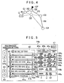
- FIG. 4 schematically shows an example of a method of adding a destination.
- FIG. 5 shows an example of a destination addition setting screen displayed by the navigation device.
- FIG. 6 shows an example of the destination addition setting screen displayed by the navigation device.
- FIG. 7 shows an example of the destination addition setting screen displayed by the navigation device.
- FIG. 8 shows an example of the destination addition setting screen displayed by the navigation device.
- FIG. 9 schematically shows another example of a method of adding a destination.
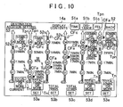
- FIG. 10 shows an example of the destination addition setting screen displayed by the navigation device.
- FIG. 1 is a block diagram showing a structure of a navigation device serving as the route display device according to the present embodiment.
- a navigation device 10 includes a control unit, a search unit, and a prediction unit, and also includes a controller 11 that performs overall control of the navigation device 10.
- the navigation device 10 includes a position detection part 12, a battery control part 13, a display 14 including a display part, and a speaker 15.
- the controller 11 includes a control part 21 including a display control unit, a vehicle-side I/F 22, a geographical information storage part 23, an image processor 24, and an audio processor 25.
- the control part 21 includes a CPU 31 for performing various kinds of calculations based on input data, a RAM 32 used as a working memory of the CPU 31 and in which route data or the like when the route has been searched is stored, and a ROM 33 which records various programs for control.
- the position detection part 12 includes a GPS receiver 34, a vehicle speed sensor 35, and a gyro sensor 36.
- the controller 11 detects an absolute position such as a longitude and latitude by electric navigation based on signals received by the GPS receiver 34.
- the controller 11 calculates a relative position from a reference position by autonomous navigation based on the signals detected by the vehicle speed sensor 35 and the gyro sensor 36. Thereafter, the controller 11 specifies a current position of a vehicle by combining the absolute position and the relative position output from the position detection part 12.
- the battery control part 13 controls charging and discharging electric power of a vehicular battery that is charged by connecting a charging connector with an electric power supply source such as an outlet outside the vehicle.
- the battery control part 13 calculates a SOC (State of Charge) indicating a remaining amount of the battery in a method of prediction from an open voltage value of the battery or an electric current accumulation method of accumulating charged electric current value of the battery. Thereafter, using the remaining amount of the battery output from the battery control part 13, the controller 11 predicts a remaining amount Er0 of the battery at the current position, a remaining amount Er of the battery on a searched route, a charging fee Cv required for charging, and a charging time Tv required for charging.
- SOC State of Charge
- the image processor 24 creates various kinds of image data based on control signals from the control part 21 to display on a display part 14a of the display 14, and outputs the created image data to the display 14.
- the image processor 24 displays a plurality of searched routes from a departure point to a final destination and a destination addition setting screen for setting a guidance route from the plurality of searched routes on the display part 14a of the display 14.
- the image processor 24 also displays a map screen in which a vehicle index indicating a current position of the vehicle is overlapped on the map screen with an emphasized set guidance route on the display part 14a.
- the image processor 24 displays traffic information, operation guidance, an operation menu, key guidance, guidance information along the guidance route on the display part 14a of the display 14.
- the display 14 includes a plurality of operation switches such as various keys and buttons that receive operations from a user. When the respective operation switches are pressed, various kinds of instruction commands are output from the display 14 to the controller 11. For example, after the destination addition setting screen for setting a plurality of destinations and the departure point has been displayed on the display 14, if the plurality of destinations and the departure point are output from the display 14 to the controller 11, the controller 11 searches for a plurality of routes from the departure point to the final destination via the plurality of destinations. In addition, after the plurality of searched routes have been displayed on the display 14, if one searched route among the plurality of searched routes is output as the guidance route from the display 14 to the controller 11, the controller 11 starts route guidance according to the guidance route.
- the controller 11 starts route guidance according to the guidance route.
- the audio processor 25 reads audio data from an audio data storage in the audio processor 25 to output various kinds of guidance audio from the speaker 15.
- the geographical information storage part 23 is an external storage medium such as a hard disk, an optical disk, and the like.
- the geographical information storage part 23 stores data for displaying a map image, the traffic information, the searched route, and the guidance route, and various kinds of data for using calculation of the searched route and the guidance route.
- the geographical information storage part 23 stores node data Dnd regarding nodes, link data Dlk regarding links, route search data Dsc for searching for routes to destinations, search data Drt for searching for positions, map data Dmp for displaying a map, consumption amount prediction data Dcv indicating relation between a travel route and a consumption amount of the battery, and facility data Dcf regarding charging facilities.
- the various kinds of data stored in the geographical information storage part 23 is updated in receiving information distributed from an information distribution center for example.
- the nodes are set at branches such as intersections, T-shaped roads, and the like, terminal points of roads, and the like.
- the node data Dnd includes node IDs identifying such nodes in association with positions of the nodes, attributes of the nodes, and identifiers of the respective links connected to the nodes.
- the link data Dlk includes link IDs identifying links in association with the node IDs of connected nodes, road attributes such as the number of lanes, road widths, road inclination, downgrade roads, upgrade roads and the like, link lengths, road types such as national roads, highways, and the like, traffic regulation information such as one-way, road fees, and the like.
- the search data Dsc includes cost data used for calculating a search cost that is total of nodes costs, link costs and the like, travel times required to pass through links, route display data for displaying the guidance route on the map of the display 14, and the like.
- cost data used for calculating a search cost that is total of nodes costs, link costs and the like, travel times required to pass through links, route display data for displaying the guidance route on the map of the display 14, and the like.
- the value of the node cost is set according to the travel route such as a direct advance, a right turn, or a left turn in passing through the intersection and presence or absence of a signal.
- the value of the link cost is set based on the road attribute, the road type, the road width, the number of lanes, the link length, and the like, which are included in the link data Dlk.
- the controller 11 searches for routes in which the plurality of destinations are stopped by in different stopping-by orders. In such a case, the controller 11 searches for a route for each of all stopping-by orders such that the searched cost becomes the smallest under the conditions such as travel distance priority, general road priority, toll road priority, travel time priority, fee priority, and the like.
- the controller 11 calculates, for each searched route, travel information including a travel distance D from the departure point to the final destination, a required time T, a travel fee Cf, and a travelable position which can be reached with the remaining amount Er of the battery.
- route information is associated with the stopping-by order for each searched route and displayed in the destination addition setting screen.
- the route information includes the information indicating the travel distance D, the required time T, the travel fee Cf, and a necessity of charging.
- the map data Dmp is data for displaying the map screen on the display 14 and is hierarchized in accordance with information amount of road network.
- the map data Dmp is sectioned by meshes having an area size that varies between hierarchized layers, and configured such that a mesh ID for identifying a mesh is associated with road shape data for drawing curve sections of roads and background data for drawing areas other than the roads.
- the consumption amount prediction data Dcv is data in which a length and an inclination of the route are associated with a consumption amount of the battery required to travel the route.
- the controller 11 calculates the searched route for each of all stopping-by orders, the controller 11 calculates a travel area which can be reached with the remaining amount Er (for example, the remaining amount Er0) at the current position (for example, the departure point) for each route based on the length and the inclination of the searched route and the consumption amount prediction data Dcv.
- the controller 11 calculates a position on the route that is farthest from the current position (for example, the departure point) in the travel area as the travelable position.
- the facility data Dcf includes a facility ID for identifying a facility, a position of the facility, a type of the facility, and the like.
- the type of the facility in the facility data Dcf includes a charging facility.
- the data regarding the charging facility further includes a charging speed that is a charging amount for a certain time period, a fee that is required for charging, and the like.
- the charging speed indicating charging capacity of the charging facility is standardized with three types of fast charging, doubled-speed charging, and normal charging. The charging speeds of these three types increase in the following order: the normal charging, the doubled-speed charging, and the fast charging.
- the charged amount of the battery reaches the designated charged amount by 30-minute charging in case of the fast charging facility.
- 120-minute charging is necessary in case of the doubled-speed charging facility, and 360-minute charging in case of the normal charging facility.
- the above-mentioned charging speed is a value that changes every minute depending on the condition of the battery such as the remaining amount Er of the battery [Wh], the temperature of the battery, and the like. Therefore, in order to utilize a more accurate charging speed, it is preferable to adjust a constant representing the capacity of each of the above-mentioned charging facilities with the condition of the battery.
- the remaining amount at the charging facility is assumed to be the remaining amount Er after charging at the charging facility, i.e., the designated charging amount, and the controller 11 executes various kinds of processing based on this assumption. That is, under the assumption that charging is executed at the charging facility, the controller 11 calculates, for each searched route, the travel information including the travel distance D of the searched route, the required time T for traveling the searched route, and the travel fee Cf required to travel the searched route in the following manner.
- the designated charging amount is for example a fully-charged amount, 80% of the fully-charged amount, or an arbitrary value set by the user.
- FIG. 2 is a flow chart showing the procedure according to the destination addition setting processing.
- FIG. 3 is a flow chart showing the procedure of route information calculation processing in the destination addition setting processing.
- FIG. 4 schematically shows an example of a method of adding a destination.
- the destination addition setting processing in the navigation device 10 can be realized by hardware including various kinds of circuits, as well as by software having a route display program as a main program, which is read from the ROM 33 or the geographical information storage part 23.
- a route display program as a main program, which is read from the ROM 33 or the geographical information storage part 23.
- the destination addition setting processing in the navigation device 10 can be realized by the software.
- the controller 11 judges to start the destination addition setting processing when an ignition switch is turned on. Thereafter, the controller 11 waits until an adding command for a destination is input on the display 14, that is, a setting command for a plurality of destinations is input on the display 14 (Step S10).
- the controller 11 searches for adding positions of an added destination, that is, the stopping-by orders of the plurality of destinations such that the routes in which the plurality of destinations are stopped by in different stopping-by orders are structured (Step S20).
- the controller 11 searches for, as the adding positions of the newly added destination, a position before (on the side of the departure point from) a destination in the previously-set route and a position after (on the side of the final destination from) a destination in the previously-set route.
- the current position of the vehicle C is set as the departure point and a route is set with a route element R1, a route element R2, a route element R3, and a route element R4, which connect the following sections of (a) to (d).
- a visit purpose of one destination is closely related to a visit purpose of another destination in the stopping-by order.
- the stopping-by order of the destination G4 has to be after the destination G3.
- the relative stopping-by order of the destinations having such mutual relation is preferably maintained in order that routes meeting the user's intention are searched.
- Step S30 When the adding positions of the new destination are searched, routes are searched for the respective adding positions of the new destination.
- the controller 11 calculates the travel distance D, the travel time Ts, and the road fee Cr for all searched routes. That is, the routine of the route information calculation processing shown in FIG. 3 is executed (Step S30).
- the destinations are firstly treated as the destinations not including a charging facility.
- the route information for one searched route of which route information is not calculated yet among the plurality of searched routes is calculated by respectively adding the travel distances D, the required times T, and the travel fees Cf of the route elements forming the one searched route (Step S33).
- the controller 11 acquires the current (at the time of departure) remaining amount Er (Er0) of the battery at the current position (at the departure point) from the battery control part 13 (Step S34).
- the controller 11 calculates a route position on the searched route which can be reached with the remaining amount Er0, that is, the travelable position in the one searched route is calculated (Step S35).
- the controller 11 determines whether the travelable position in the one searched route is after the final destination (that is, in the direction opposite to the departure point) (Step S36).
- Step S36 If it is determined that the travelable position is after the final destination (Step S36: YES), the route information calculation processing for the one searched route is terminated and the controller 11 treats the above-mentioned route information as the route information of the one searched route. Subsequently, the controller 11 determines whether the calculation processing of the route information has been completed for all the searched routes, that is, whether the number of calculation n is equal to the route number N (Step S37).
- Step S37: NO If it is determined that the calculation processing of the route information is not completed for all the searched routes yet (n ⁇ N) (Step S37: NO), the procedure returns to Step S32, and Step S32 and the subsequent processing is executed. On the other hand, if it is determined that the calculation processing of the route information has been completed for all the searched routes (Step S37: YES), the respective numerical values of the route number N that was temporarily stored in the RAM 32 and the number of calculation n that was counted up are cleared (Step S38). Thereafter, the routine of the route information calculation processing is terminated.
- Step S36 determines whether a destination including a charging facility exists before (on the current position (the departure point) side of) the travelable position (Step S39).
- Step S39 If it is determined that a destination including a charging facility does not exist before (on the current position (the departure point) side of) the travelable position (Step S39: YES), the controller 11 determines that the final destination cannot be reached on the searched route, that is, the searched route is an unreachable route. Thereafter, the controller 11 updates the route information of the searched route such that the information indicating that the searched route is an unreachable route is added to the route information of the searched route (Step S40). Thereafter, the controller 11 transits to the above-mentioned processing of Step S37.
- Step S39 the controller 11 calculates the charging time Tv required for charging at the destination including the charging facility based on the remaining amount Er when the vehicle arrives at the destination including the charging facility and the designated charging amount Ers (Step S41). Thereafter, the controller 11 calculates the required time T for traveling the searched route by adding the travel time Ts of the searched route to the charging time Tv. In addition, at Step 541, the controller 11 also calculates the charging fee Cv required at the destination including the charging facility based on the remaining amount Er when the vehicle arrives at the destination including the charging facility and the designated charging amount Ers. Thereafter, the controller 11 calculates the travel fee Cf required to travel the searched route by adding the road fee Cr of the searched route to the charging fee Cv.
- the controller 11 calculates the route position which can be reached from the destination including the charging facility with the designated charging amount Ers, that is, the travelable position (Step S42). Subsequently, the controller 11 determines whether the travelable position is after the final destination (Step S43). If it is determined that the travelable position is after the final destination (Step S43: YES), the controller 11 determines that the searched route is the route on which the final destination can be reached by charging, that is, the searched route is a charging-required route.
- Step S44 the controller 11 updates the route information of the searched route such that the information indicating that the searched route is the charging-required route is added to the route information in a charging processing completed status.
- Step S44 the controller 11 transits to the above-mentioned processing of Step S37.
- Step S43: NO the controller 11 determines that the searched route is the route on which the final destination cannot be reached even when charging is executed at the destination including the charging facility, that is, the searched route is an unreachable route.
- Step S45 the controller 11 updates the route information of the searched route such that the information indicating that the searched route is the unreachable route is added to the route information in the charging processing completed status.
- the controller 11 transits to the above-mentioned processing of Step S37.
- the destination addition setting screen in which the route information, the necessity of charging, and the stopping-by order are associated for each searched route, is displayed on the display part 14a. Thereafter, the destination addition setting processing is terminated (Step S50).
- FIG. 5 shows an example of the destination addition setting screen displayed on the display part 14a of the navigation device 10.
- the destination addition setting screen shown in FIG. 5 is the display screen with a white background, and displays an example in which the new destination G5 is added to the route connecting the destinations G1 to G4, as shown in FIG. 4 .
- the destinations G1, G3, G4, and G5 are points not including a charging facility CF.
- the destination G2 is a point including the charging facility CF.
- the vehicle index serving as the index of the vehicle and destination indexes serving as the indexes of the respective destinations G1 to G4 are allocated on a route index 40 serving as the index of the route in the stopping-by order from the lower side to the upper side of the screen.
- a route index 40 serving as the index of the route in the stopping-by order from the lower side to the upper side of the screen.
- name sections 41a, 41b, 41c, 41d, and 41e are provided on the right side of the vehicle index and the destination indexes in the screen.
- a charging facility index CFa indicating that the destination corresponding to the destination index includes the charging facility is displayed.
- the user can recognize that only the destination G2 includes the charging facility among the destinations G1 to G4. In addition, when the charging facility index CFa is not displayed, the user can recognize that the destinations other than the destination G2 do not include the charging facility.
- various operation buttons 43 for scrolling or skipping on the display part 14a the respective destination indexes allocated on the route index 40 are displayed.
- the operation button 43 in which an up-pointing arrow is drawn is pressed, the destination indexes and the name sections are scrolled or skipped upward the screen in the following order: the destinations G4, G3, G2, and G1.
- the operation button 43 in which a down-pointing arrow is drawn is pressed, the destination indexes and the name sections are scrolled or skipped downward the screen in the following order: the destinations G1, G2, G3, and G4.
- Such operation buttons 43 are used to rearrange the order of the destination indexes displayed on the route index 40, that is, to change the stopping-by order of the destinations, or to delete the destination index displayed on the route index 40, that is, to cancel the destination setting.
- an adding destination index serving as the index of the newly-adding destination G5 is displayed on the upper side of the route index 40 in the screen.
- a name section 42 in which the name of the newly-adding destination is displayed, is provided.
- the destination index displayed on the route index 40 is added each time the name of a newly-adding destination is input in the name section 42.
- route information display sections 44a, 44b, 44c, 44d, and 44e in which the route information of the corresponding searched routes is displayed, are provided.
- the required time T, the travel distance D, the travel fee Cf, and a charging index CFb indicating that further charging is required are displayed as the route information.
- the charging index CFb it is indicated that further charging at a destination other than the set destinations is required.
- the charging index CFb is not displayed, it is indicated that further charging at a destination other than the set destinations is not required.
- the necessity of charging is associated with the stopping-by order for each of the plurality of searched routes having different stopping-by orders of the destinations, and displayed. Therefore, it is possible to make the user recognize the necessity of charging, that is, whether all the destinations can be reached with the limited remaining amount Er of the battery for each of the plurality of searched routes having different stopping-by orders of the destinations.
- the route in which the charging is required it is possible to encourage the user in setting the destinations to take a measure such as newly-adding a charging facility as a destination, moving a destination including a charging facility that is already set as a stop-by destination closer to the final destination, and selecting a stopping-by order in which the charging is not required.
- the required time T, the travel distance D, and the travel fee Cf are associated with the stopping-by order for each route, and displayed. That is, most of the travel information given from the searched route is associated with the searched route, and displayed together with the travel information of other searched routes on a list. Therefore, according to such destination addition setting screen, it becomes easy for the user not only to recognize the travel information for each searched route but also to compare the travel information between the searched routes.
- the route information display section 44a corresponding to the first searched route index "95 min., 60 km, 310 yen (blank)" is displayed as the route information of the first searched route calculated in the destination addition setting processing.
- the route information display section 44b corresponding to the second searched route index "94 min., 59 km, 310 yen (blank)" is displayed as the route information of the second searched route calculated in the destination addition setting processing.
- the first searched route and the second searched route corresponding to the route information display sections 44a and 44b are the routes that were determined as the charging-required routes in the above-mentioned destination addition setting processing.
- the charging index CFb indicating that the charging is required is not displayed in either the route information display sections 44a or 44b. That is, it becomes easy to make the user recognize that, in these two routes having different stopping-by orders of the destinations G1 to G5, the charging at another charging facility than the destination G2 is not required, that is, all the destinations can be reached by the charging at the destination G2.
- the battery is normally charged up to the designated charging amount Ers at the charging facility. If an increase of the remaining amount Er by the charging is not reflected into the necessity of charging although the charging is performed at the charging facility, the accuracy of the information regarding the necessity of charging is lowered.
- the charging facility is set as the destination G2 located within the travel area and it is predicted that the remaining amount Er at the charging facility is the designated charging amount Ers. For the route after the destination G2, the necessity of charging is predicted based on the travelable position which can be reached with the designated charging amount Ers. That is, the charging amount at the charging facility is considered; therefore, it is possible to increase the accuracy of the information regarding the necessity of charging.
- the criteria of the user in selecting a searched route from the plurality of searched routes include the required time T for traveling the searched route.
- the required time T for traveling the searched route includes the charging time Tv at the charging facility. Therefore, if the charging facility is included in the destinations G1 to G5, it is possible to provide the user with the information on the required time T including the charging time Tv at the charging facility. Therefore, it is possible to make the user recognize for example that the second searched route should be selected if the guidance route is selected with priority on the required time T.
- the criteria of the user in selecting a searched route from the plurality of searched routes also include the travel fee Cf required to travel the searched route.
- the travel fee Cf required to travel the route includes the charging fee Cv at the charging facility. Therefore, if the charging facility is included in the destinations G1 to G5, it is possible to previously provide the user with the information on the travel fee Cf in which the charging fee Cv at the charging facility is reflected. Therefore, it is possible to make the user recognize for example that the second searched route should be selected if the guidance route is selected with priority on the travel fee Cf.
- the contents are displayed in red.
- the contents are displayed in black. Therefore, the contents displayed in the route information display sections 44c to 44e are visually enhanced compared to the other route information display sections 44a and 44b.
- the third searched route, the fourth searched route, and the fifth searched route corresponding to the route information display sections 44c to 44e are the routes that were determined as the unreachable routes in the above-mentioned destination addition setting processing.
- the charging index CFb indicating that the charging is required is displayed in all of the route information display sections 44c to 44e.
- the charging is required at another charging facility than the destination G2, that is, all the destinations cannot be reached only by the charging at the destination G2 that is the destination including the charging facility.
- the third searched route, the fourth searched route, and the fifth searched route it is possible to encourage the user in setting the destinations to take a measure such as newly-adding a charging facility as a destination, moving the destination G2 including the charging facility that is already set as a stop-by destination closer to the final destination, and selecting a stopping-by order in which the charging is not required.
- a required time button 45a On the upper side of the required times T in the route information display sections 44a to 44e in the screen, a required time button 45a is displayed. On the upper side of the travel distances D in the route information display sections 44a to 44e in the screen, a travel distance button 45b is displayed. On the upper side of the travel fees Cf in the route information display sections 44a to 44e in the screen, a travel fee button 45c is displayed.
- the required time button 45a outputs a display command for displaying the details of the required time T for each searched route to the controller 11.
- the travel distance button 45b outputs a display command for displaying the details of the travel distance D for each searched route to the controller 11.
- the travel fee button 45c outputs a display command for displaying the details of the travel fee Cf for each searched route to the controller 11.
- the screen changes to the destination addition setting screen, in which the details of the required time T for each searched route are displayed.
- the travel distance button 45b is pressed, the screen changes to the destination addition setting screen, in which the details of the travel distance D for each searched route are displayed.
- the travel fee button 45c is pressed, the screen changes to the destination addition setting screen, in which the details of the travel fee Cf for each searched route are displayed.
- FIGS. 6 to 8 are the destination addition setting screen, in which the details of the required time T are displayed, the destination addition setting screen, in which the details of the travel distance D are displayed, and the destination addition setting screen, in which the details of the travel fee Cf are displayed, respectively.
- FIGS. 6 to 8 show examples when the new destination G5 is added to the route connecting the destinations G1 to G5, similar to FIG. 5 .
- the destination addition setting screens in which the details of the travel distance D and the travel fee Cf are displayed, have a display parameter different from the destination addition setting screen, in which the details of the required time T are displayed; however, the other main configurations are the same. Therefore, such different points are specially explained below.
- the vehicle index serving as the index of the vehicle and the destination indexes serving as the indexes of the destinations G1 to G4 are allocated on the route index serving as the index of each route in the stopping-by order from the lower side to the upper side of the screen.
- An initial route index 52 serves as the index of the previously-set route.
- the following five route indexes (a) to (e) corresponding to the respective routes are displayed.
- the travelable position index 52s is displayed on the upper side of the destination index of the destination G4 in the screen, and the area from the vehicle index to the travelable position index 52s is displayed in blue. Therefore, it is possible to make the user recognize because of the difference in the displayed color that the vehicle can travel from the current position to after the destination G4 if the first searched route is selected as the guidance route.
- the travelable position index 52s is displayed on the upper side of the destination index of the destination G4 in the screen, similar to the first searched route index 52a. Therefore, it is possible to make the user recognize because of the difference in the displayed color that the vehicle can travel from the current position to after the destination G4.
- the travelable position index 52s is displayed on the lower side of the destination index of the destination G4 in the screen, and the area from the vehicle index to the travelable position index 52s is displayed in blue. Therefore, it is possible to make the user recognize because of the difference in the displayed color that the charging is required at another charging facility than the destination G2, that is, the destination G4 cannot be reached only by the charging at the destination G2 if the third searched route is selected as the guidance route. Also, in the fourth searched route index 52d and the fifth searched route index 52e, the travelable position index 52s is displayed on the lower side of the destination index of the destination G4 in the screen, similar to the third searched route index 52c. Therefore, it is possible to make the user recognize because of the difference in the displayed color that the destination G4 cannot be reached only by the charging at the destination G2.
- the first searched route index 52a to the fifth searched route index 52e are arranged from the left to the right of the screen. And also, the displayed positions of the destination indexes in the respective searched route indexes are aligned in the vertical direction of the screen. Therefore, it becomes easy for the user to compare the travelable position indexes 52s between the searched routes. Further, it becomes possible to make the user easily recognize how the travelable position index 52s changes when the adding position of the destination G5 is changed, or which is the farthest destination the vehicle can reach. Consequently, for the route in which the charging is further required, it is possible to more appropriately encourage the user to take a measure such as newly-adding a charging facility as a destination, and moving a charging facility closer to the final destination.
- the charging facility index CFa and a charging-required index CFc are displayed respectively.
- the charging facility index CFa serves as the index of whether the destination includes the charging facility, similar to the above-mentioned destination addition setting screen, and represents that the charging is performed at the charging facility.
- the charging-required index CFc serves as the index of the position where the charging becomes necessary, and represents that no charging facility exists at the position.
- the required time for arriving at the reachable destination is displayed next to the index of the corresponding destination in black as an arrival time Tp, and the required time for arriving at the unreachable destination is displayed next to the index of the corresponding destination in red as a lower limit arrival time Tpn.
- the required time T of the reachable route is displayed next to the index of the corresponding searched route, and a lower limit required time Tn of the unreachable route is displayed next to the index of the corresponding searched route.
- a time for arriving at the destination G2 and a time of departure from the destination G2, that is, the charging time Tv is displayed.
- the details of the required time given from the searched route such as the required time for traveling to each destination is associated with the corresponding searched route, and displayed together with those of the other searched routes on a list. Therefore, it becomes easy for the user not only to recognize the details of the required time for each searched route, but also to compare the details of the required times between the searched routes.
- the third searched route index 52c "Total 101 min. "or more” is displayed as the lower limit required time Tn, and "17 min. 52 min.” is displayed on the right side of the destination G2 in the screen. Therefore, it is possible to make the user easily recognize that it takes at least 101 minutes to arrive at the destination G4 as the final destination and the charging at the destination G2 also takes 35 minutes if the third searched route is selected as the guidance route.
- the fourth searched route index 52d "Total 105 min. "or more”” is displayed as the lower limit required time Tn, and "17 min. 52 min.” is displayed on the right side of the destination G2 in the screen.
- a required time button 51a serves as the index indicating the current displayed contents, and is displayed at a higher luminance level than the other buttons 51b and 51c in order to indicate that the displayed contents are the details of the required time T.
- the travel distance button 51b outputs a display command for displaying the details of the travel distance D for each searched route to the controller 11.
- the travel fee button 51c outputs a display command for displaying the details of the travel fee Cf for each searched route to the controller 11.
- setting buttons 53a, 53b, 53c, 53d, and 53e for setting the searched routes corresponding to the first to fifth searched route indexes as the guidance routes are displayed.
- the searched route corresponding to the setting button is set as the guidance route.
- the screen changes to the destination addition setting screen, in which the details of the travel distance D is displayed.
- the destination addition setting screen in which the details of the travel distance D is displayed, has a display parameter different from the destination addition setting screen of FIG. 6 , in which the details of the required time T are displayed; however, the other main configurations are the same.
- the travel distance for arriving at the reachable destination is displayed next to the index of the corresponding destination in black as an arrival distance Dp
- the travel distance for arriving at the unreachable destination is displayed next to the index of the corresponding destination in red as a lower limit arrival distance Dpn.
- the travel distance D of the reachable route is displayed next to the index of the corresponding searched route in black
- a lower limit travel distance Dn of the unreachable route is displayed next to the index of the corresponding searched route in red.
- the details of the travel distance given from the searched route such as the travel distance required to travel to each destination is associated with the corresponding searched route, and displayed together with those of the other searched routes. Therefore, it becomes easy for the user not only to recognize the details of the travel distance for each searched route, but also to compare the details of the travel distances between the searched routes.
- the screen changes to the destination addition setting screen, in which the details of the travel fee Cf is displayed.
- the destination addition setting screen in which the details of the travel fee is displayed, has a display parameter different from the destination addition setting screens of FIGS. 6 and 7 , in which the details of the required time T and the travel distance D are displayed; however, the other main configurations are the same.
- the travel fee including the charging fee for arriving at the reachable destination is displayed next to the index of the corresponding destination in black as an destination fee Cfp, and the travel fee including the charging fee for arriving at the unreachable destination is displayed next to the index of the corresponding destination in red as a lower limit destination fee Cpn.
- the travel fee Cf of the reachable route is displayed next to the index of the corresponding searched route in black, and a lower limit travel fee Cfn of the unreachable route is displayed next to the index of the corresponding searched route in red.
- the details of the travel fee given from the searched route such as the travel fee required to travel to each destination is associated with the corresponding searched route, and displayed together with those of the other searched routes. Therefore, it becomes easy for the user not only to recognize the details of the travel fee for each searched route, but also to compare the details of the travel fees between the searched routes.
- the above embodiment can be modified and realized as appropriate as indicated below.
- the route information if it is determined based on the remaining amount Er0 of the battery at the current position such as the departure point that the travelable position is after the final destination (Step S36: YES), the route information, which was calculated under the assumption that no charging facility exists on the searched route, is treated as the route information on the searched route.
- the after-mentioned calculated result (a), (b), and (c) may be used as the route information.
- a destination including a charging facility is set as a destination to be stopped-by, it is normally supposed that charging is performed at the destination.
- some drivers only intend to stay at the destination for a short period of time.
- it is preferable in selecting a route that the charging-not-required route that is a route in which the final destination can be reached without charging at the destination including the charging facility and the charging-required route that is a route in which the final destination can be reached by charging at the destination including the charging facility are displayed in a visually-recognized manner.
- the charging-required route and the unreachable route may be displayed in a visually-not-recognized manner.
- the route is the charging-not-required route may be displayed in a visually-recognized manner. That is, the updated contents at Step S40, Step S44, and Step S45 in the flow chart of FIG. 3 may not be displayed.
- the driver may not perform charging at such destination.
- the route is the charging-not-required route that is a route in which the final destination can be reached only with the remaining amount of the battery at the current position serving as the departure point is displayed in a visually-recognized manner.
- the destination G5 not including the charging facility is newly added.
- the destination G5 including the charging facility may be newly added.
- the destination G5 including the charging facility may be newly added to the route connecting the destinations G1 to G4, any of which does not include the charging facility.
- the charging facility index CFa is displayed on the right side of the destination index of the newly-added destination G5 in the screen.
- the relative position between the travelable position index 52s and the charging facility index CFa is displayed for each searched route on a list. Therefore, it is easy to make the user recognize at which point on the route connecting the destinations G1 to G4 the charging should be performed.
- the respective searched route indexes are displayed such that the charging facility index CFa sequentially shifts in a travel direction of the routes, a change in the travel information according to a charging point can be more easily recognized compared to if the charging facility index CFa is disorderly displayed on the screen.
- the number of charging facilities included in the searched route may be two or more. If the travel information is calculated for the searched route including two or more charging facilities, the calculation of the charging time and the charging fee (Step S41), the calculation of the travelable position which can be reached with the designated charging amount (Step S42), and the determination regarding whether the travelable position is after the final destination (Step S43) are preferably executed for each charging facility.
- the stopping-by order of the destinations included in the previously-set searched route may be changed and the new destination may be added to each searched route after the change.
- new searched routes may be structured in the stopping-by orders possible for all the destinations including the destinations included in the previously-set searched route as long as the plurality of routes are searched such that the stopping-orders of the plurality of destinations are different each other.
- the destination addition setting screen is only necessary to be a screen, in which the necessity of charging is associated with the stopping-by order for each route. For example, the required time T, the travel distance D, and the travel fee Cf may not be displayed. In such configuration, it is possible to decrease information amount to be displayed in one screen. Thereby, it is possible to increase visibility of the information relating to the necessity of charging and suppress the load on the controller 11 for the display processing.
- a plurality of destination indexes and the travelable position index 52s are allocated in the travel order on the searched route index and displayed.
- the plurality of destination indexes and the travelable position index 52s may be displayed on different searched route indexes.
- a charging facility is set as a destination within the travelable area, it is predicted that the remaining amount Er of the battery at the destination is the designated charging amount Ers and the travelable position on the route that can be reached from the charging facility with the designated charging amount Ers is predicted. However, even if a charging facility is set as a destination within the travelable area, the point that can be reached with the remaining amount Er of the battery at the current position may be treated as the travelable position and various kinds of the travel information may be calculated based on such travelable position.
- the controller 11 is configured to execute all the processing (the search unit, the prediction unit, and the display control unit).
- the present invention may be realized by a route display system that displays a route of the vehicle, where a plurality of devices (for example, a center device and a terminal device) capable of mutually transmitting and receiving the information execute the respective processing.
- the center device may execute the processing of the search unit and the prediction unit and send the results to the terminal device, and the terminal device that received the results may execute the processing of the display control unit.
- the route display system may include a plurality of devices other than the above two devices.
- the route display system may include three devices such as the device to execute the processing of the search unit, the device to execute the processing of the prediction unit, and the device to execute the processing of the display control unit.
- a controller 11 included in a navigation device 10 searches for a plurality of routes having different vehicle's stopping-by orders for a plurality of destinations, predicts for each of the routes a travelable position which can be reached with a remaining amount of a battery, predicts for each of the routes a necessity of charging based on whether the travelable position is on a side of a departure point in relation to a final destination, and associates the necessity of charting with the stopping-by order for each of the routes to display on a display 14.
Landscapes
- Engineering & Computer Science (AREA)
- Radar, Positioning & Navigation (AREA)
- Remote Sensing (AREA)
- Automation & Control Theory (AREA)
- Physics & Mathematics (AREA)
- General Physics & Mathematics (AREA)
- Navigation (AREA)
Abstract
Description
- The present invention relates to a route display device that displays a route of a vehicle, more particularly, a route display device, a route display method, a computer program product, and a route display system that display a route for stopping by a plurality of destinations.
- In a navigation device that displays a route of a vehicle, as described in Japanese Patent Application; Publication No.
JP-A-2001-66148 JP-A-2007-155404 - Recently, electric vehicles using a battery to be charged from outside vehicle as a drive electric source for a motor, such as plug-in hybrid vehicles, battery vehicles, and the like, have received a lot of attention as environmentally-friendly vehicles. On the other hand, the users need to pay special attention to whether charging of the battery is necessary when they use the above-mentioned electric vehicles in a social infrastructure, which is structured on the basis of vehicles having an internal combustion engine as a power generation source.
- On the other hand, when a destination or the stopping-by order is changed as mentioned above, a length of a guidance route often changes. If the guidance route becomes long due to the change of the stopping-by order or the like, a final destination may not be reached by EV drive using the motor as a power source. In addition, if a charging facility is included in one of the plurality of destinations, a distance between a departure point and the charging facility may change. In such a case, even if the final destination can be reached, a charging time at the charging facility, especially a travel time for arriving at the final destination can largely change.
- As a result, as long as the vehicle to be used is an electric vehicle, if the destinations and/or the stopping-by order are changed as described in the above-mentioned Japanese Patent Application; Publication No.
JP-A-2001-66148 JP-A-2007-155404 - In light of the problem described above, it is an object of the present invention to provide a route display device, a route display method, a route display program, and a route display system that are capable of providing information on routes meeting the intention of the user that utilizes the electric vehicle.
- Hereinafter, methods to solve the above-mentioned problem and their effects are described.
The invention described in a first aspect of the present invention is characterized in that a route display device that displays a route of a vehicle includes: a search unit that searches for a plurality of routes in which a plurality of destinations are stopped by in different stopping-by orders; a prediction unit that predicts, for each of the routes, a travelable position which can be reached with a remaining amount of a battery and predicts, for each of the routes, a necessity of charging based on whether the travelable position is on a side of a departure point in relation to a final destination; and a display control unit that displays, for each of the routes, the necessity of charging in association with the stopping-by order on a display part. - According to the invention described in the first aspect of the present invention, the necessity of charging is associated with the stopping-by order for each of the plurality of routes having different stopping-by orders of the destinations, and displayed. Therefore, it is possible to make the user recognize the necessity of charging, that is, whether all the destinations can be reached with a limited remaining amount of the battery for each of the plurality of routes having different stopping-by orders of the destinations. In addition, for the route in which the charging is required, it is possible to encourage the user in setting the destinations to take a measure such as newly-adding a charging facility as a destination, moving a charging facility that is already set as a destination closer to the final destination, and selecting a stopping-by order in which the charging is not required. Thereby, it is possible to provide information on routes meeting the intention of the user that utilizes an electric vehicle.
- The invention described in a second aspect of the present invention is characterized in that among the plurality of routes, for a route in which a charging facility is included in the destination within a travel area which can be reached with the remaining amount, the prediction unit: predicts that the remaining amount at the charging facility will be a designated charging amount that is the remaining amount after charging at the charging facility, and the travelable position on the route which can be reached from the charging facility with the designated charging amount; and further predicts the necessity of charging based on whether the travelable position is on the side of the departure point in relation to the final destination.
- If a charging facility is set as a destination, the battery is normally charged up to the designated charging amount at the charging facility. If an increase of the remaining amount by the charging is not reflected into the above-mentioned necessity of charging although the charging is performed at the charging facility, the accuracy of the information regarding the necessity of charging is lowered.
- In this regard, according to the invention described in the second aspect of the present invention, if a charging facility is set as a destination within the travel area, it is predicted that the remaining amount at the charging facility will be the designated charging amount. For the route in a travel direction from the charging facility, the necessity of charging is predicted based on the travelable position which can be reached with the designated charging amount. Therefore, if a charging facility is included in the plurality of destinations, it is possible to increase the accuracy of the information regarding the necessity of charging.
- The invention described in a third aspect of the present invention is characterized in that the display control unit arranges and displays the plurality of destinations and the travelable position in a travel order for each of the routes.
If a plurality of destinations are set, there normally are a destination with relatively high priority and a destination with relatively low priority in the plurality of destinations. Also for the stopping-by orders in which the plurality of destinations are stopped by, there are a stopping-by order with relatively high priority and a stopping-by order with relatively low priority. Therefore, the user possibly select as a guidance route a searched route, in which all the destinations cannot be reached with the limited remaining amount of the battery as long as the destination with relatively high priority can be reached. That is, as criteria of the user in selecting a route from a plurality of routes, there is a case in which the user prioritizes the destination(s) that can be reached with the limited amount of the battery. - In this regard, according to the invention described in the third aspect of the present invention, the plurality of destinations and the travelable position are allocated in a travel order (a stopping-by order) and displayed for each of the routes; therefore, it is possible to make the user recognize at which point on the route stopping by the plurality of the destinations the charging becomes necessary, that is, which is the farthest destination the vehicle can reach with the limited remaining amount of the battery. In addition, the above-mentioned information is displayed for each of the routes; therefore, it is possible to make the user roughly recognize which destination(s) can be reached in which stopping-by order. Therefore, for the route in which the charging is required, it is possible to properly encourage the user to take a measure such as newly-adding a charging facility as a destination, or moving a charging facility that is already set as a destination closer to the final destination. In addition, for the route in which the charging is required, it is possible to make the user recognize the reachable destination(s). Therefore, it is possible to make the user select a guidance route from even the route(s) in which all the destinations cannot be reached with the limited remaining amount of the battery. Consequently, it is possible to provide information on routes meeting the user's intention based on the reachable destination(s).
- The invention described in a fourth aspect of the present invention is characterized in that the prediction unit: for each of the plurality of routes, calculates a travel time for traveling the route as a required time of the route; and among the plurality of routes, for a route in which a charging facility is included in the destination within a travel area which can be reached with the remaining amount, calculates the required time of the route by adding a charging time at the charging facility to the travel time of the route, and the display control unit displays the required time for each of the routes.
- The criteria of the user in selecting a route from the plurality of routes include the required time to travel the route. On the other hand, the charging time required to charge the battery is normally quite long compared to a fuel supply to a fuel tank, and naturally, the rate of the charging time to the above-mentioned required time is large. In addition, if the remaining amount at the charging facility changes, that is, if the length of the route to the charging facility changes, the charging time largely changes.
- In this regard, according to the invention described in the fourth aspect of the present invention, if a charging facility is set as a destination within the travel area, the charging time at the charging facility is included in the required time to travel the route. Therefore, if the charging facility is included in the plurality of destinations, the required time including the charging time at the charging facility is informed to the user. Consequently, it is possible to provide information on routes meeting the user's intention based on the required time.
- The invention described in a fifth aspect of the present invention is characterized in that the prediction unit: for each of the plurality of routes, calculates a road fee required to travel the route as a travel fee of the route; and among the plurality of routes, for a route in which a charging facility is included in the destination within a travel area which can be reached with the remaining amount, calculates the travel fee of the route by adding a charging fee at the charging facility to the road fee of the route, and the display control unit displays the travel fee for each of the routes.
- The criteria of the user in selecting a route from the plurality of routes include the travel fee required to travel the route. On the other hand, if the charging is performed within the travel area, the rate of the charging fee to the travel fee is too large to ignore. In addition, if the remaining amount at the charging facility changes, that is, if the length of the route to the charging facility changes, the travel fee also changes.
- In this regard, according to the invention described in the fifth aspect of the present invention, if a charging facility is set as a destination within the travel area, the charging fee at the charging facility is included in the travel fee required to travel the route. Therefore, if the charging facility is included in the plurality of destinations, the travel fee to which the charging fee at the charging facility is reflected is informed to the user. Consequently, it is possible to provide information on routes meeting the user's intention based on the travel fee.
- The invention described in a sixth aspect of the present invention is characterized in that, if a new destination is added to a previously-set route, the search unit searches for a route stopping by the new destination on the side of the departure point in relation to a destination included in the previously-set route and a route stopping by the new destination on the side of the final destination in relation to the destination included in the previously-set route.
- In a route that stops by the plurality of destinations, a visit purpose of one destination is often closely related to a visit purpose of another destination. The relative stopping-by order of the destinations including such relation is preferably maintained to search for a route meeting the user's intention.
- In this regard, according to the invention described in the sixth aspect of the present invention, if a new destination is added to a previously-set route, routes are searched such that the new destination is stopped by on the side of the departure point and on the side of the final destination in relation to a destination included in the previously-set route. Therefore, a plurality of routes are searched in such manner that the relative stopping-by order of the destinations in the previously-set route is maintained. Consequently, in a case where the destinations are closely related each other as above, it is possible to provide information on routes meeting the user's intention.
- The invention described in a seventh aspect of the present invention is characterized in that a route display method for displaying a route of a vehicle includes the steps of: searching for a plurality of routes in which a plurality of destinations are stopped by in different stopping-by orders; predicting, for each of the routes, a travelable position which can be reached with a remaining amount of a battery and predicting, for each of the routes, a necessity of charging based on whether the travelable position is on a side of a departure point in relation to a final destination; and displaying, for each of the routes, the necessity of charging in association with the stopping-by order.
- According to the invention described in the seventh aspect of the present invention, the necessity of charging is associated with the stopping-by order for each of the plurality of routes having different stopping-by orders of the destinations, and displayed. Therefore, it is possible to make the user recognize the necessity of charging, that is, whether all the destinations can be reached with a limited remaining amount of the battery for each of the plurality of routes having different stopping-by orders of the destinations. In addition, for the route in which the charging is required, it is possible to encourage the user in setting the destinations to take a measure such as newly-adding a charging facility as a destination, moving a charging facility that is already set as a destination closer to the final destination, and selecting a stopping-by order in which the charging is not required. Therefore, it is possible to provide information on routes meeting the intention of the user that utilizes an electric vehicle.
- The invention described in an eighth aspect of the present invention is characterized by a computer program product including a program for a processing device, comprising software code portions for performing the steps according to a route display method for displaying a route of a vehicle includes the steps of: searching for a plurality of routes in which a plurality of destinations are stopped by in different stopping-by orders; predicting, for each of the routes, a travelable position which can be reached with a remaining amount of a battery and predicting, for each of the routes, a necessity of charging based on whether the travelable position is on a side of a departure point in relation to a final destination; and displaying, for each of the routes, the necessity of charging in association with the stopping-by order..
- According to the invention described in the eighth aspect of the present invention, the necessity of charging is associated with the stopping-by order for each of the plurality of routes having different stopping-by orders of the destinations, and displayed. Therefore, it is possible to make the user recognize the necessity of charging, that is, whether all the destinations can be reached with a limited remaining amount of the battery for each of the plurality of routes having different stopping-by orders of the destinations. In addition, for the route in which the charging is required, it is possible to encourage the user in setting the destinations to take a measure such as newly-adding a charging facility as a destination, moving a charging facility that is already set as a destination closer to the final destination, and selecting a stopping-by order in which the charging is not required. Therefore, it is possible to provide information on routes meeting the intention of the user that utilizes an electric vehicle.
- The invention described in a ninth aspect of the present invention is characterized in that the computer program product comprises a computer-readable medium on which the software code portions are stored, wherein the program is directly loadable into an internal memory of the processing device.
- The invention described in a tenth aspect of the present invention is characterized in that a route display system including a plurality of devices capable of mutually transmitting and receiving information that displays a route of a vehicle, the route display system includes: a search unit that searches for a plurality of routes in which a plurality of destinations are stopped by in different stopping-by orders; a prediction unit that predicts, for each of the routes, a travelable position which can be reached with a remaining amount of a battery and predicts, for each of the routes, a necessity of charging based on whether the travelable position is on a side of a departure point in relation to a final destination; and a display control unit that displays, for each of the routes, the necessity of charging in association with the stopping-by order on a display part.
- According to the invention described in the tenth aspect of the present invention, by mutually transmitting and receiving information between the plurality of devices, the necessity of charging is associated with the stopping-by order for each of the plurality of routes having different stopping-by orders of the destinations, and displayed. Therefore, it is possible to make the user recognize the necessity of charging, that is, whether all the destinations can be reached with a limited remaining amount of the battery for each of the plurality of routes having different stopping-by orders of the destinations. In addition, for the route in which the charging is required, it is possible to encourage the user in setting the destinations to take a measure such as newly-adding a charging facility as a destination, moving a charging facility that is already set as a destination closer to the final destination, and selecting a stopping-by order in which the charging is not required. Thereby, it is possible to provide information on routes meeting the intention of the user that utilizes an electric vehicle.
-
FIG. 1 is a block diagram showing a structure of a navigation device in a specific embodiment, the navigation device in which a route display device according to the present invention is implemented. -
FIG. 2 is a flow chart showing a procedure of destination addition setting processing executed by the navigation device. -
FIG. 3 is a flow chart showing a procedure of route information calculation processing in the destination addition setting processing. -
FIG. 4 schematically shows an example of a method of adding a destination. -
FIG. 5 shows an example of a destination addition setting screen displayed by the navigation device. -
FIG. 6 shows an example of the destination addition setting screen displayed by the navigation device. -
FIG. 7 shows an example of the destination addition setting screen displayed by the navigation device. -
FIG. 8 shows an example of the destination addition setting screen displayed by the navigation device. -
FIG. 9 schematically shows another example of a method of adding a destination. -
FIG. 10 shows an example of the destination addition setting screen displayed by the navigation device. - Hereinafter, a specific embodiment of a route display device, a route display method, and a route display program according to the present invention will be explained in detail with reference to
FIGS. 1 to 8 .FIG. 1 is a block diagram showing a structure of a navigation device serving as the route display device according to the present embodiment. - A
navigation device 10 includes a control unit, a search unit, and a prediction unit, and also includes acontroller 11 that performs overall control of thenavigation device 10. In addition, thenavigation device 10 includes aposition detection part 12, abattery control part 13, adisplay 14 including a display part, and aspeaker 15. - The
controller 11 includes acontrol part 21 including a display control unit, a vehicle-side I/F 22, a geographicalinformation storage part 23, animage processor 24, and anaudio processor 25. Thecontrol part 21 includes aCPU 31 for performing various kinds of calculations based on input data, aRAM 32 used as a working memory of theCPU 31 and in which route data or the like when the route has been searched is stored, and aROM 33 which records various programs for control. - The
position detection part 12 includes aGPS receiver 34, avehicle speed sensor 35, and agyro sensor 36. Thecontroller 11 detects an absolute position such as a longitude and latitude by electric navigation based on signals received by theGPS receiver 34. In addition, thecontroller 11 calculates a relative position from a reference position by autonomous navigation based on the signals detected by thevehicle speed sensor 35 and thegyro sensor 36. Thereafter, thecontroller 11 specifies a current position of a vehicle by combining the absolute position and the relative position output from theposition detection part 12. - The
battery control part 13 controls charging and discharging electric power of a vehicular battery that is charged by connecting a charging connector with an electric power supply source such as an outlet outside the vehicle. Thebattery control part 13 calculates a SOC (State of Charge) indicating a remaining amount of the battery in a method of prediction from an open voltage value of the battery or an electric current accumulation method of accumulating charged electric current value of the battery. Thereafter, using the remaining amount of the battery output from thebattery control part 13, thecontroller 11 predicts a remaining amount Er0 of the battery at the current position, a remaining amount Er of the battery on a searched route, a charging fee Cv required for charging, and a charging time Tv required for charging. - The
image processor 24 creates various kinds of image data based on control signals from thecontrol part 21 to display on adisplay part 14a of thedisplay 14, and outputs the created image data to thedisplay 14. Theimage processor 24 displays a plurality of searched routes from a departure point to a final destination and a destination addition setting screen for setting a guidance route from the plurality of searched routes on thedisplay part 14a of thedisplay 14. In addition, theimage processor 24 also displays a map screen in which a vehicle index indicating a current position of the vehicle is overlapped on the map screen with an emphasized set guidance route on thedisplay part 14a. Further, theimage processor 24 displays traffic information, operation guidance, an operation menu, key guidance, guidance information along the guidance route on thedisplay part 14a of thedisplay 14. - The
display 14 includes a plurality of operation switches such as various keys and buttons that receive operations from a user. When the respective operation switches are pressed, various kinds of instruction commands are output from thedisplay 14 to thecontroller 11. For example, after the destination addition setting screen for setting a plurality of destinations and the departure point has been displayed on thedisplay 14, if the plurality of destinations and the departure point are output from thedisplay 14 to thecontroller 11, thecontroller 11 searches for a plurality of routes from the departure point to the final destination via the plurality of destinations. In addition, after the plurality of searched routes have been displayed on thedisplay 14, if one searched route among the plurality of searched routes is output as the guidance route from thedisplay 14 to thecontroller 11, thecontroller 11 starts route guidance according to the guidance route. - The
audio processor 25 reads audio data from an audio data storage in theaudio processor 25 to output various kinds of guidance audio from thespeaker 15.
The geographicalinformation storage part 23 is an external storage medium such as a hard disk, an optical disk, and the like. The geographicalinformation storage part 23 stores data for displaying a map image, the traffic information, the searched route, and the guidance route, and various kinds of data for using calculation of the searched route and the guidance route. Specifically, the geographicalinformation storage part 23 stores node data Dnd regarding nodes, link data Dlk regarding links, route search data Dsc for searching for routes to destinations, search data Drt for searching for positions, map data Dmp for displaying a map, consumption amount prediction data Dcv indicating relation between a travel route and a consumption amount of the battery, and facility data Dcf regarding charging facilities. The various kinds of data stored in the geographicalinformation storage part 23 is updated in receiving information distributed from an information distribution center for example. - The nodes are set at branches such as intersections, T-shaped roads, and the like, terminal points of roads, and the like. The node data Dnd includes node IDs identifying such nodes in association with positions of the nodes, attributes of the nodes, and identifiers of the respective links connected to the nodes.
- The link data Dlk includes link IDs identifying links in association with the node IDs of connected nodes, road attributes such as the number of lanes, road widths, road inclination, downgrade roads, upgrade roads and the like, link lengths, road types such as national roads, highways, and the like, traffic regulation information such as one-way, road fees, and the like.
- The search data Dsc includes cost data used for calculating a search cost that is total of nodes costs, link costs and the like, travel times required to pass through links, route display data for displaying the guidance route on the map of the
display 14, and the like. In a case where a subject node is set to an intersection for example, the value of the node cost is set according to the travel route such as a direct advance, a right turn, or a left turn in passing through the intersection and presence or absence of a signal. The value of the link cost is set based on the road attribute, the road type, the road width, the number of lanes, the link length, and the like, which are included in the link data Dlk. - When information regarding a plurality of destinations and a departure point is output from the
display 14 to thecontroller 11, thecontroller 11 searches for routes in which the plurality of destinations are stopped by in different stopping-by orders. In such a case, thecontroller 11 searches for a route for each of all stopping-by orders such that the searched cost becomes the smallest under the conditions such as travel distance priority, general road priority, toll road priority, travel time priority, fee priority, and the like. When the searched route for each of all stopping-by orders is acquired, thecontroller 11 calculates, for each searched route, travel information including a travel distance D from the departure point to the final destination, a required time T, a travel fee Cf, and a travelable position which can be reached with the remaining amount Er of the battery. In addition, route information is associated with the stopping-by order for each searched route and displayed in the destination addition setting screen. The route information includes the information indicating the travel distance D, the required time T, the travel fee Cf, and a necessity of charging. When the user selects a searched route based on the destination addition setting screen, the selected searched route is output from thedisplay 14 to thecontroller 11. Then, thecontroller 11 sets the selected searched route as the guidance route and starts route guidance. - The map data Dmp is data for displaying the map screen on the
display 14 and is hierarchized in accordance with information amount of road network. The map data Dmp is sectioned by meshes having an area size that varies between hierarchized layers, and configured such that a mesh ID for identifying a mesh is associated with road shape data for drawing curve sections of roads and background data for drawing areas other than the roads. - The consumption amount prediction data Dcv is data in which a length and an inclination of the route are associated with a consumption amount of the battery required to travel the route. When the
controller 11 calculates the searched route for each of all stopping-by orders, thecontroller 11 calculates a travel area which can be reached with the remaining amount Er (for example, the remaining amount Er0) at the current position (for example, the departure point) for each route based on the length and the inclination of the searched route and the consumption amount prediction data Dcv. Thecontroller 11 calculates a position on the route that is farthest from the current position (for example, the departure point) in the travel area as the travelable position. - The facility data Dcf includes a facility ID for identifying a facility, a position of the facility, a type of the facility, and the like. The type of the facility in the facility data Dcf includes a charging facility. The data regarding the charging facility further includes a charging speed that is a charging amount for a certain time period, a fee that is required for charging, and the like. The charging speed indicating charging capacity of the charging facility is standardized with three types of fast charging, doubled-speed charging, and normal charging. The charging speeds of these three types increase in the following order: the normal charging, the doubled-speed charging, and the fast charging. For example, when a current charged amount is 30% and a designated charged amount is 80%, the charged amount of the battery reaches the designated charged amount by 30-minute charging in case of the fast charging facility. On the other hand, 120-minute charging is necessary in case of the doubled-speed charging facility, and 360-minute charging in case of the normal charging facility. The above-mentioned charging speed is a value that changes every minute depending on the condition of the battery such as the remaining amount Er of the battery [Wh], the temperature of the battery, and the like. Therefore, in order to utilize a more accurate charging speed, it is preferable to adjust a constant representing the capacity of each of the above-mentioned charging facilities with the condition of the battery.
- If a charging facility is included in the destination(s) within the travel area, the remaining amount at the charging facility is assumed to be the remaining amount Er after charging at the charging facility, i.e., the designated charging amount, and the
controller 11 executes various kinds of processing based on this assumption. That is, under the assumption that charging is executed at the charging facility, thecontroller 11 calculates, for each searched route, the travel information including the travel distance D of the searched route, the required time T for traveling the searched route, and the travel fee Cf required to travel the searched route in the following manner. The designated charging amount is for example a fully-charged amount, 80% of the fully-charged amount, or an arbitrary value set by the user. - Specifically, if a charging facility is included in the destination(s) within the travel area, the
controller 11 calculates the distance travelable from the charging facility with a designated charging amount Ers.
In addition, based on the remaining amount Er when the vehicle arrives at the charging facility, thecontroller 11 calculates the charging time Tv required for charging at the charging facility using the above-mentioned facility data Dcf. Thereafter, thecontroller 11 calculates the required time T for traveling the searched route by adding a travel time Ts of the searched route to the above-mentioned charging time Tv (Required Time T = Travel Time Ts + Charging Time Tv). - In addition, based on the remaining amount Er when the vehicle arrives at the charging facility, the
controller 11 calculates the charging fee Cv required for charging at the charging facility using the above-mentioned facility data Dcf. Thereafter, thecontroller 11 calculates the travel fee Cf required to travel the searched route by adding a road fee Cr for the searched route to the above-mentioned charging fee Cv (Travel Fee Cf = Road Fee Cr + Charging Fee Cv). - Next, the procedure according to destination addition setting processing in the
navigation device 10 is explained with reference toFIGS. 2 to 4 .FIG. 2 is a flow chart showing the procedure according to the destination addition setting processing.FIG. 3 is a flow chart showing the procedure of route information calculation processing in the destination addition setting processing. In addition,FIG. 4 schematically shows an example of a method of adding a destination. - The destination addition setting processing in the
navigation device 10 can be realized by hardware including various kinds of circuits, as well as by software having a route display program as a main program, which is read from theROM 33 or the geographicalinformation storage part 23. Hereinafter, an example is explained, in which the destination addition setting processing in thenavigation device 10 can be realized by the software. - The
controller 11 judges to start the destination addition setting processing when an ignition switch is turned on. Thereafter, thecontroller 11 waits until an adding command for a destination is input on thedisplay 14, that is, a setting command for a plurality of destinations is input on the display 14 (Step S10). - When the setting command for the plurality of destinations is input on the display 14 (Step S10: YES), the
controller 11 searches for adding positions of an added destination, that is, the stopping-by orders of the plurality of destinations such that the routes in which the plurality of destinations are stopped by in different stopping-by orders are structured (Step S20). In the present embodiment, thecontroller 11 searches for, as the adding positions of the newly added destination, a position before (on the side of the departure point from) a destination in the previously-set route and a position after (on the side of the final destination from) a destination in the previously-set route. For example, as shown inFIG. 4 , the current position of the vehicle C is set as the departure point and a route is set with a route element R1, a route element R2, a route element R3, and a route element R4, which connect the following sections of (a) to (d). -
- (a) Between the vehicle C and a destination G1 (C-G1): Route element R1
- (b) Between the destination G1 and a destination G2 (G1-G2): Route element R2
- (c) Between the destination G2 and a destination G3 (G2-G3): Route element R3
- (d) Between the destination G3 and a destination G4 (G3-G4): Route element R4
- In a route in which the plurality of destinations are stopped by, there is a case in which a visit purpose of one destination is closely related to a visit purpose of another destination in the stopping-by order. For example, if the above destination G4 is a home of a user's friend and the above destination G3 is a department store where the user is going to buy a gift for the friend, the stopping-by order of the destination G4 has to be after the destination G3. The relative stopping-by order of the destinations having such mutual relation is preferably maintained in order that routes meeting the user's intention are searched.
- In case of the above configuration in which the new destination G5 is added to the previously-set route, routes are searched such that the new destination G5 is stopped by before and after each of the destinations G1 to G4 included in the previously-set route. Therefore, new routes are searched in a condition in which the relative stopping-by order of the previously-set destinations G1 to G4 is maintained. Consequently, if the destinations are closely related each other in the stopping-by order as mentioned above, it is possible to search for routes that further meet the user's intention.
- When the adding positions of the new destination are searched, routes are searched for the respective adding positions of the new destination. The
controller 11 calculates the travel distance D, the travel time Ts, and the road fee Cr for all searched routes. That is, the routine of the route information calculation processing shown inFIG. 3 is executed (Step S30). - In the routine of the route information calculation processing, as shown in
FIG. 3 , a route if the new destination is added is searched for each of the adding positions of the new destination searched at S20, as well as the number of the searched routes (a route number) N is temporarily stored in the RAM 32 (Step S31). Subsequently, a numerical value indicating the number of calculation n of the route information is counted up by one (Step S32). Note that an initial numerical value of the number of calculation n of the route information is zero. For example, if five routes are searched, the route number (N=5) is temporarily stored and calculation processing is executed five times in order to sequentially calculate the route information for the respective five routes (n=1, 2, 3, 4, 5). In calculating the route information, all the destinations are firstly treated as the destinations not including a charging facility. The route information for one searched route of which route information is not calculated yet among the plurality of searched routes is calculated by respectively adding the travel distances D, the required times T, and the travel fees Cf of the route elements forming the one searched route (Step S33). - Next, the
controller 11 acquires the current (at the time of departure) remaining amount Er (Er0) of the battery at the current position (at the departure point) from the battery control part 13 (Step S34). When the remaining amount Er0 at the current position is acquired, thecontroller 11 calculates a route position on the searched route which can be reached with the remaining amount Er0, that is, the travelable position in the one searched route is calculated (Step S35). Then, thecontroller 11 determines whether the travelable position in the one searched route is after the final destination (that is, in the direction opposite to the departure point) (Step S36). - If it is determined that the travelable position is after the final destination (Step S36: YES), the route information calculation processing for the one searched route is terminated and the
controller 11 treats the above-mentioned route information as the route information of the one searched route. Subsequently, thecontroller 11 determines whether the calculation processing of the route information has been completed for all the searched routes, that is, whether the number of calculation n is equal to the route number N (Step S37). - If it is determined that the calculation processing of the route information is not completed for all the searched routes yet (n < N) (Step S37: NO), the procedure returns to Step S32, and Step S32 and the subsequent processing is executed. On the other hand, if it is determined that the calculation processing of the route information has been completed for all the searched routes (Step S37: YES), the respective numerical values of the route number N that was temporarily stored in the
RAM 32 and the number of calculation n that was counted up are cleared (Step S38). Thereafter, the routine of the route information calculation processing is terminated. - On the other hand, if it is determined at Step S36 that the travelable position is not after the final destination (Step S36: NO), the
controller 11 determines whether a destination including a charging facility exists before (on the current position (the departure point) side of) the travelable position (Step S39). - If it is determined that a destination including a charging facility does not exist before (on the current position (the departure point) side of) the travelable position (Step S39: YES), the
controller 11 determines that the final destination cannot be reached on the searched route, that is, the searched route is an unreachable route. Thereafter, thecontroller 11 updates the route information of the searched route such that the information indicating that the searched route is an unreachable route is added to the route information of the searched route (Step S40). Thereafter, thecontroller 11 transits to the above-mentioned processing of Step S37. - On the other hand, if it is determined that a destination including a charging facility exists before (on the current position side of) the travelable position (Step S39: NO), the
controller 11 calculates the charging time Tv required for charging at the destination including the charging facility based on the remaining amount Er when the vehicle arrives at the destination including the charging facility and the designated charging amount Ers (Step S41). Thereafter, thecontroller 11 calculates the required time T for traveling the searched route by adding the travel time Ts of the searched route to the charging time Tv. In addition, at Step 541, thecontroller 11 also calculates the charging fee Cv required at the destination including the charging facility based on the remaining amount Er when the vehicle arrives at the destination including the charging facility and the designated charging amount Ers. Thereafter, thecontroller 11 calculates the travel fee Cf required to travel the searched route by adding the road fee Cr of the searched route to the charging fee Cv. - When the charging time Tv, the required time T, the charging fee Cv, and the travel fee Cf are calculated, the
controller 11 calculates the route position which can be reached from the destination including the charging facility with the designated charging amount Ers, that is, the travelable position (Step S42). Subsequently, thecontroller 11 determines whether the travelable position is after the final destination (Step S43). If it is determined that the travelable position is after the final destination (Step S43: YES), thecontroller 11 determines that the searched route is the route on which the final destination can be reached by charging, that is, the searched route is a charging-required route. Then, thecontroller 11 updates the route information of the searched route such that the information indicating that the searched route is the charging-required route is added to the route information in a charging processing completed status (Step S44). When the processing at Step S44 is terminated, thecontroller 11 transits to the above-mentioned processing of Step S37. On the other hand, when it is determined that the travelable position is not after the final destination (Step S43: NO), thecontroller 11 determines that the searched route is the route on which the final destination cannot be reached even when charging is executed at the destination including the charging facility, that is, the searched route is an unreachable route. Then, thecontroller 11 updates the route information of the searched route such that the information indicating that the searched route is the unreachable route is added to the route information in the charging processing completed status (Step S45). When the processing at Step S45 is terminated, thecontroller 11 transits to the above-mentioned processing of Step S37. - When the route information is calculated for all searched routes that are structured for the respective adding positions, the destination addition setting screen, in which the route information, the necessity of charging, and the stopping-by order are associated for each searched route, is displayed on the
display part 14a. Thereafter, the destination addition setting processing is terminated (Step S50). - Next, an example of the destination addition setting screen output by the above-mentioned destination addition setting processing is explained with reference to
FIG. 5. FIG. 5 shows an example of the destination addition setting screen displayed on thedisplay part 14a of thenavigation device 10. The destination addition setting screen shown inFIG. 5 is the display screen with a white background, and displays an example in which the new destination G5 is added to the route connecting the destinations G1 to G4, as shown inFIG. 4 . Here, the destinations G1, G3, G4, and G5 are points not including a charging facility CF. The destination G2 is a point including the charging facility CF. - As shown in
FIG. 5 , in the destination addition setting screen shown in thedisplay part 14a, the vehicle index serving as the index of the vehicle and destination indexes serving as the indexes of the respective destinations G1 to G4 are allocated on aroute index 40 serving as the index of the route in the stopping-by order from the lower side to the upper side of the screen. On the right side of the vehicle index and the destination indexes in the screen,name sections - On the left side of the charging facility index CFa in the screen,
various operation buttons 43 for scrolling or skipping on thedisplay part 14a the respective destination indexes allocated on theroute index 40 are displayed. When theoperation button 43 in which an up-pointing arrow is drawn is pressed, the destination indexes and the name sections are scrolled or skipped upward the screen in the following order: the destinations G4, G3, G2, and G1. On the other hand, when theoperation button 43 in which a down-pointing arrow is drawn is pressed, the destination indexes and the name sections are scrolled or skipped downward the screen in the following order: the destinations G1, G2, G3, and G4.Such operation buttons 43 are used to rearrange the order of the destination indexes displayed on theroute index 40, that is, to change the stopping-by order of the destinations, or to delete the destination index displayed on theroute index 40, that is, to cancel the destination setting. - On the upper side of the
route index 40 in the screen, an adding destination index serving as the index of the newly-adding destination G5 is displayed. On the right side of the adding destination index in the screen, aname section 42, in which the name of the newly-adding destination is displayed, is provided. The destination index displayed on theroute index 40 is added each time the name of a newly-adding destination is input in thename section 42. By means of thick arrows extending from thename section 42 of the destination G5, with which the adding positions of the destination G5 are indicated, the following five searched route indexes serving as the indexes of the searched routes are displayed. - The index of a first searched route having the adding position in the above (a) C-G1: First searched route index
The index of a second searched route having the adding position in the above (b) G1-G2: Second searched route index
The index of a third searched route having the adding position in the above (c) G2-G3: Third searched route index
The index of a fourth searched route having the adding position in the above (d) G3-G4: Fourth searched route index
The index of a fifth searched route having the adding position in the above (e) after G4: Fifth searched route index
On the right side of the above first to fifth searched route indexes in the screen, settingbuttons setting buttons 46a to 46e is pressed, the searched route corresponding to the setting button is set as the guidance route. - On the right side of the
setting buttons 46a to 46e in the screen, routeinformation display sections information display sections 44a to 44e, the required time T, the travel distance D, the travel fee Cf, and a charging index CFb indicating that further charging is required are displayed as the route information. When the charging index CFb is displayed, it is indicated that further charging at a destination other than the set destinations is required. On the other hand, when the charging index CFb is not displayed, it is indicated that further charging at a destination other than the set destinations is not required. - According to the destination addition setting screen having such configuration, the necessity of charging is associated with the stopping-by order for each of the plurality of searched routes having different stopping-by orders of the destinations, and displayed. Therefore, it is possible to make the user recognize the necessity of charging, that is, whether all the destinations can be reached with the limited remaining amount Er of the battery for each of the plurality of searched routes having different stopping-by orders of the destinations. In addition, for the route in which the charging is required, it is possible to encourage the user in setting the destinations to take a measure such as newly-adding a charging facility as a destination, moving a destination including a charging facility that is already set as a stop-by destination closer to the final destination, and selecting a stopping-by order in which the charging is not required. Further, besides the necessity of charging, the required time T, the travel distance D, and the travel fee Cf are associated with the stopping-by order for each route, and displayed. That is, most of the travel information given from the searched route is associated with the searched route, and displayed together with the travel information of other searched routes on a list. Therefore, according to such destination addition setting screen, it becomes easy for the user not only to recognize the travel information for each searched route but also to compare the travel information between the searched routes.
- For example, in the route
information display section 44a corresponding to the first searched route index, "95 min., 60 km, 310 yen (blank)" is displayed as the route information of the first searched route calculated in the destination addition setting processing. In addition, in the routeinformation display section 44b corresponding to the second searched route index, "94 min., 59 km, 310 yen (blank)" is displayed as the route information of the second searched route calculated in the destination addition setting processing. - The first searched route and the second searched route corresponding to the route
information display sections information display sections - If a charging facility is set as a destination, the battery is normally charged up to the designated charging amount Ers at the charging facility. If an increase of the remaining amount Er by the charging is not reflected into the necessity of charging although the charging is performed at the charging facility, the accuracy of the information regarding the necessity of charging is lowered. In this regard, according to the above-mentioned destination addition setting processing, the charging facility is set as the destination G2 located within the travel area and it is predicted that the remaining amount Er at the charging facility is the designated charging amount Ers. For the route after the destination G2, the necessity of charging is predicted based on the travelable position which can be reached with the designated charging amount Ers. That is, the charging amount at the charging facility is considered; therefore, it is possible to increase the accuracy of the information regarding the necessity of charging.
- In addition, the criteria of the user in selecting a searched route from the plurality of searched routes include the required time T for traveling the searched route. In this regard, according to the above-mentioned configuration, the required time T for traveling the searched route includes the charging time Tv at the charging facility. Therefore, if the charging facility is included in the destinations G1 to G5, it is possible to provide the user with the information on the required time T including the charging time Tv at the charging facility. Therefore, it is possible to make the user recognize for example that the second searched route should be selected if the guidance route is selected with priority on the required time T.
- In addition, the criteria of the user in selecting a searched route from the plurality of searched routes also include the travel fee Cf required to travel the searched route. In this regard, according to the above-mentioned configuration, if a charging facility is set as a destination within the travel area, the travel fee Cf required to travel the route includes the charging fee Cv at the charging facility. Therefore, if the charging facility is included in the destinations G1 to G5, it is possible to previously provide the user with the information on the travel fee Cf in which the charging fee Cv at the charging facility is reflected. Therefore, it is possible to make the user recognize for example that the second searched route should be selected if the guidance route is selected with priority on the travel fee Cf.
- On the other hand, in the route
information display section 44c corresponding to the third searched route, "101 min. "or more", 71 km, 300 yen "or more" (required)" is displayed as the route information of the third searched route calculated in the destination addition setting processing. In addition, in the routeinformation display section 44d corresponding to the fourth searched route, "105 min. "or more", 75 km, 400 yen "or more" (required)" is displayed as the route information of the fourth searched route calculated in the destination addition setting processing. Further, in the routeinformation display section 44e corresponding to the fifth searched route, "112 min. "or more", 82 km, 400 yen "or more" (required)" is displayed as the route information of the fifth searched route calculated in the destination addition setting processing. - In these three route
information display sections 44c to 44e, the contents are displayed in red. On the other hand, in the above-mentioned two routeinformation display sections information display sections 44c to 44e are visually enhanced compared to the other routeinformation display sections information display sections 44c to 44e are the routes that were determined as the unreachable routes in the above-mentioned destination addition setting processing. Further, the charging index CFb indicating that the charging is required is displayed in all of the routeinformation display sections 44c to 44e. That is, it is possible to make the user clearly recognize that, in the three routes having different stopping-by orders of the destinations G1 to G5, the charging is required at another charging facility than the destination G2, that is, all the destinations cannot be reached only by the charging at the destination G2 that is the destination including the charging facility. For the third searched route, the fourth searched route, and the fifth searched route, it is possible to encourage the user in setting the destinations to take a measure such as newly-adding a charging facility as a destination, moving the destination G2 including the charging facility that is already set as a stop-by destination closer to the final destination, and selecting a stopping-by order in which the charging is not required. - On the upper side of the required times T in the route
information display sections 44a to 44e in the screen, a requiredtime button 45a is displayed. On the upper side of the travel distances D in the routeinformation display sections 44a to 44e in the screen, atravel distance button 45b is displayed. On the upper side of the travel fees Cf in the routeinformation display sections 44a to 44e in the screen, a travel fee button 45c is displayed. The requiredtime button 45a outputs a display command for displaying the details of the required time T for each searched route to thecontroller 11. Thetravel distance button 45b outputs a display command for displaying the details of the travel distance D for each searched route to thecontroller 11. The travel fee button 45c outputs a display command for displaying the details of the travel fee Cf for each searched route to thecontroller 11. - When the required
time button 45a is pressed, the screen changes to the destination addition setting screen, in which the details of the required time T for each searched route are displayed. When thetravel distance button 45b is pressed, the screen changes to the destination addition setting screen, in which the details of the travel distance D for each searched route are displayed. When the travel fee button 45c is pressed, the screen changes to the destination addition setting screen, in which the details of the travel fee Cf for each searched route are displayed. - Next, an example of the destination addition setting screen, in which the details of the required time T, the travel distance D, and the travel fee Cf are displayed, is explained with reference to
FIGS. 6 to 8. FIGS. 6 to 8 are the destination addition setting screen, in which the details of the required time T are displayed, the destination addition setting screen, in which the details of the travel distance D are displayed, and the destination addition setting screen, in which the details of the travel fee Cf are displayed, respectively.FIGS. 6 to 8 show examples when the new destination G5 is added to the route connecting the destinations G1 to G5, similar toFIG. 5 . The destination addition setting screens, in which the details of the travel distance D and the travel fee Cf are displayed, have a display parameter different from the destination addition setting screen, in which the details of the required time T are displayed; however, the other main configurations are the same. Therefore, such different points are specially explained below. - As shown in
FIG. 6 , in the destination addition setting screen shown in thedisplay part 14a, the vehicle index serving as the index of the vehicle and the destination indexes serving as the indexes of the destinations G1 to G4 are allocated on the route index serving as the index of each route in the stopping-by order from the lower side to the upper side of the screen. Aninitial route index 52 serves as the index of the previously-set route. In the destination addition setting screen, besides theinitial route index 52, the following five route indexes (a) to (e) corresponding to the respective routes are displayed. - The index of the searched route having the adding position in the above (a) C-G1: First searched
route index 52a
The index of the searched route having the adding position in the above (b) G1-G2: Second searchedroute index 52b
The index of the searched route having the adding position in the above (c) G2-G3: Third searchedroute index 52c
The index of the searched route having the adding position in the above (d) G3-G4: Fourth searchedroute index 52d
The index of the searched route having the adding position in the above (e) after G4: Fifth searchedroute index 52e
Atravelable position index 52s serving as the index of the travelable position is displayed in each of the searchedroute indexes 52a to 52e, such that a relative positional relation among the destinations G1 to G4 and the travelable position is maintained in the destination addition setting screen, which clearly indicates the relative positional relation between the respective destination indexes and thetravelable position index 52s. - For example, in the first searched
route index 52a, thetravelable position index 52s is displayed on the upper side of the destination index of the destination G4 in the screen, and the area from the vehicle index to thetravelable position index 52s is displayed in blue. Therefore, it is possible to make the user recognize because of the difference in the displayed color that the vehicle can travel from the current position to after the destination G4 if the first searched route is selected as the guidance route. In addition, in the second searchedroute index 52b, thetravelable position index 52s is displayed on the upper side of the destination index of the destination G4 in the screen, similar to the first searchedroute index 52a. Therefore, it is possible to make the user recognize because of the difference in the displayed color that the vehicle can travel from the current position to after the destination G4. - On the other hand, in the third searched
route index 52c, thetravelable position index 52s is displayed on the lower side of the destination index of the destination G4 in the screen, and the area from the vehicle index to thetravelable position index 52s is displayed in blue. Therefore, it is possible to make the user recognize because of the difference in the displayed color that the charging is required at another charging facility than the destination G2, that is, the destination G4 cannot be reached only by the charging at the destination G2 if the third searched route is selected as the guidance route. Also, in the fourth searchedroute index 52d and the fifth searchedroute index 52e, thetravelable position index 52s is displayed on the lower side of the destination index of the destination G4 in the screen, similar to the third searchedroute index 52c. Therefore, it is possible to make the user recognize because of the difference in the displayed color that the destination G4 cannot be reached only by the charging at the destination G2. - The first searched
route index 52a to the fifth searchedroute index 52e are arranged from the left to the right of the screen. And also, the displayed positions of the destination indexes in the respective searched route indexes are aligned in the vertical direction of the screen. Therefore, it becomes easy for the user to compare thetravelable position indexes 52s between the searched routes. Further, it becomes possible to make the user easily recognize how thetravelable position index 52s changes when the adding position of the destination G5 is changed, or which is the farthest destination the vehicle can reach. Consequently, for the route in which the charging is further required, it is possible to more appropriately encourage the user to take a measure such as newly-adding a charging facility as a destination, and moving a charging facility closer to the final destination. - On the right side of each searched route index in the screen, more specifically, on the right side of the destination index of the destination G2 and the right side of the
travelable position index 52s in the screen, the charging facility index CFa and a charging-required index CFc are displayed respectively. The charging facility index CFa serves as the index of whether the destination includes the charging facility, similar to the above-mentioned destination addition setting screen, and represents that the charging is performed at the charging facility. In addition, the charging-required index CFc serves as the index of the position where the charging becomes necessary, and represents that no charging facility exists at the position. When the charging facility index CFa and the charging-required index Cfc are displayed, it becomes easy to compare between the searched routes regarding at which point on the respective searched routes the charging is performed, or at which point the charging should be performed. - On the farther right side of each searched route index in the screen, the required time for arriving at the reachable destination is displayed next to the index of the corresponding destination in black as an arrival time Tp, and the required time for arriving at the unreachable destination is displayed next to the index of the corresponding destination in red as a lower limit arrival time Tpn. In addition, on the right side of the vehicle index in the screen, the required time T of the reachable route is displayed next to the index of the corresponding searched route, and a lower limit required time Tn of the unreachable route is displayed next to the index of the corresponding searched route. Further, on the right side of the charging facility index CFa in the screen, a time for arriving at the destination G2 and a time of departure from the destination G2, that is, the charging time Tv is displayed.
- According to the destination addition setting screen having such configuration, the details of the required time given from the searched route such as the required time for traveling to each destination is associated with the corresponding searched route, and displayed together with those of the other searched routes on a list. Therefore, it becomes easy for the user not only to recognize the details of the required time for each searched route, but also to compare the details of the required times between the searched routes.
- For example, in the first searched
route index 52a, "Total 95 min." is displayed as the required time T, and also "23 min. 58 min." is displayed on the right side of the destination G2 in the screen. Therefore, it is possible to make the user easily recognize that it takes 95 minutes to arrive at the destination G4 as the final destination and the charging at the destination G2 takes 35 minutes if the first searched route is selected as the guidance route. - On the other hand, in the third searched
route index 52c, "Total 101 min. "or more" is displayed as the lower limit required time Tn, and "17 min. 52 min." is displayed on the right side of the destination G2 in the screen. Therefore, it is possible to make the user easily recognize that it takes at least 101 minutes to arrive at the destination G4 as the final destination and the charging at the destination G2 also takes 35 minutes if the third searched route is selected as the guidance route. In the fourth searchedroute index 52d, "Total 105 min. "or more"" is displayed as the lower limit required time Tn, and "17 min. 52 min." is displayed on the right side of the destination G2 in the screen. Further, on the right side of the index of the destination G4 and the index of the destination G5 in the screen, "77 min. "or more"" and "105 min. "or more"" are displayed as the lower limit arrival time Tpn. Therefore, it is possible to make the user easily recognize because of the difference in the displayed color that it takes at least 105 minutes to arrive at the destination G4 as the final destination and the charging at the destination G2 also takes 35 minutes if the fourth searched route is selected as the guidance route. - On the upper side of the first to fifth searched
route indexes 52a to 52e in the screen, a requiredtime button 51a, atravel distance button 51b, and atravel fee button 51c are displayed. The requiredtime button 51a serves as the index indicating the current displayed contents, and is displayed at a higher luminance level than theother buttons travel distance button 51b outputs a display command for displaying the details of the travel distance D for each searched route to thecontroller 11. Thetravel fee button 51c outputs a display command for displaying the details of the travel fee Cf for each searched route to thecontroller 11. - On the lower side of the first to fifth searched
route index 52a to 52e, settingbuttons setting buttons 53a to 53e is pressed, the searched route corresponding to the setting button is set as the guidance route. - In the above display status, if the
travel distance button 51b is pressed, the screen changes to the destination addition setting screen, in which the details of the travel distance D is displayed. As shown inFIG. 7 , the destination addition setting screen, in which the details of the travel distance D is displayed, has a display parameter different from the destination addition setting screen ofFIG. 6 , in which the details of the required time T are displayed; however, the other main configurations are the same. On the right side of each of the searchedroute indexes 52a to 52e in the screen, the travel distance for arriving at the reachable destination is displayed next to the index of the corresponding destination in black as an arrival distance Dp, and the travel distance for arriving at the unreachable destination is displayed next to the index of the corresponding destination in red as a lower limit arrival distance Dpn. In addition, on the right side of the vehicle index in the screen, the travel distance D of the reachable route is displayed next to the index of the corresponding searched route in black, and a lower limit travel distance Dn of the unreachable route is displayed next to the index of the corresponding searched route in red. - According to the destination addition setting screen having such configuration, the details of the travel distance given from the searched route such as the travel distance required to travel to each destination is associated with the corresponding searched route, and displayed together with those of the other searched routes. Therefore, it becomes easy for the user not only to recognize the details of the travel distance for each searched route, but also to compare the details of the travel distances between the searched routes.
- In the above display status, if the
travel fee button 51c is pressed, the screen changes to the destination addition setting screen, in which the details of the travel fee Cf is displayed. As shown inFIG. 8 , the destination addition setting screen, in which the details of the travel fee is displayed, has a display parameter different from the destination addition setting screens ofFIGS. 6 and 7 , in which the details of the required time T and the travel distance D are displayed; however, the other main configurations are the same. On the right side of each of the searchedroute indexes 52a to 52e in the screen, the travel fee including the charging fee for arriving at the reachable destination is displayed next to the index of the corresponding destination in black as an destination fee Cfp, and the travel fee including the charging fee for arriving at the unreachable destination is displayed next to the index of the corresponding destination in red as a lower limit destination fee Cpn. In addition, on the right side of the vehicle index in the screen, the travel fee Cf of the reachable route is displayed next to the index of the corresponding searched route in black, and a lower limit travel fee Cfn of the unreachable route is displayed next to the index of the corresponding searched route in red. - According to the destination addition setting screen having such configuration, the details of the travel fee given from the searched route such as the travel fee required to travel to each destination is associated with the corresponding searched route, and displayed together with those of the other searched routes. Therefore, it becomes easy for the user not only to recognize the details of the travel fee for each searched route, but also to compare the details of the travel fees between the searched routes.
- As described above, according to the above-mentioned route display device, the route display method, and the route display program, the following effects can be obtained.
- (1) The charging index CFb is associated with the stopping-by order for each of the plurality of searched routes having different stopping-by orders of the destinations, and displayed. Therefore, it is possible to make the user recognize the necessity of charging, that is, whether all the destinations can be reached with the limited remaining amount of the battery for each of the plurality of searched routes having different stopping-by orders of the destinations.
-
- (2) The destination indexes displayed in the stopping-by order and the
travelable position index 52s are displayed on the searched route index for each of the plurality of searched routes having different stopping-by orders of the destinations. Therefore, it is possible to make the user recognize the necessity of charging, that is, whether all the destinations can be reached with the limited remaining amount Er of the battery for each of the plurality of searched routes having different stopping-by orders of the destinations. -
- (3) In addition, for the searched route in which the charging is further required, it is possible to encourage the user in setting the destinations to take a measure such as newly-adding a charging facility as a destination, moving a destination including a charging facility that is already set as a stop-by destination closer to the final destination, and selecting a stopping-by order in which the charging is not required.
-
- (4) If a charging facility is set as a destination within the travel area, it is predicted that the remaining amount Er at the charging facility is the designated charging amount Ers. For the route after the charging facility, the necessity of charging is predicted based on the travelable position which can be reached with the designated charging amount Ers. Therefore, if the charging facility is included in the plurality of destinations, the accuracy of the information regarding the necessity of charging can be increased.
-
- (5) A plurality of destination indexes and the travelable position index are allocated in a travel order (the stopping-by order) and displayed for each searched route index; therefore, it is possible to make the user recognize at which point on the route stopping by the plurality of the destinations the charging becomes necessary, that is, which is the farthest destination the vehicle can reach with the limited remaining amount Er of the battery. In addition, the above-mentioned information is displayed for each searched route; therefore, it is possible to make the user roughly recognize which destination(s) can be reached in which stopping-by order.
-
- (6) If a charging facility is set as a destination within the travel area, the required time T for traveling the searched route includes the charging time Tv at the charging facility. Therefore, if the charging facility is included in the plurality of destinations, the required time T including the charging time Tv at the charging facility is informed to the user.
-
- (7) If a charging facility is set as a destination within the travel area, the travel fee Cf required to travel the searched route includes the charging fee Cv at the charging facility. Therefore, if the charging facility is included in the plurality of destinations, it is possible to previously inform the user of the travel fee Cf in which the charging fee Cv at the charging facility is reflected.
-
- (8) If a new destination is added to the previously-set searched route, new routes are searched such that the new destination is stopped by before and after a destination included in the previously-set searched route. Therefore, a plurality of searched routes are newly searched in such manner that a relative stopping-by order of the destinations in the previously-set searched route is maintained. Therefore, if the destinations are closely related each other in the stopping-by order, it is possible to provide information on routes that meet the user's intention.
- In addition, the above embodiment can be modified and realized as appropriate as indicated below.
In the above-mentioned route information calculation processing, if it is determined based on the remaining amount Er0 of the battery at the current position such as the departure point that the travelable position is after the final destination (Step S36: YES), the route information, which was calculated under the assumption that no charging facility exists on the searched route, is treated as the route information on the searched route. However, when a charging facility is set as a destination, even if it is determined based on the remaining amount Er0 at the current position that the travelable position is after the final destination, the after-mentioned calculated result (a), (b), and (c) may be used as the route information. -
- (a) The required time calculated by adding the charging time required for the charging at the charging facility to the travel time of the searched route.
- (b) The travel fee calculated by adding the charging fee required for the charging at the charging facility based on the remaining amount of the battery at the time of arrival at the charging facility to the road fee required to travel the searched route.
-
- (c) The travelable position which can be reached from the charging facility with the designated charging amount Ers.
- If a destination including a charging facility is set as a destination to be stopped-by, it is normally supposed that charging is performed at the destination. However, some drivers only intend to stay at the destination for a short period of time. For such drivers, it is preferable in selecting a route that the charging-not-required route that is a route in which the final destination can be reached without charging at the destination including the charging facility and the charging-required route that is a route in which the final destination can be reached by charging at the destination including the charging facility are displayed in a visually-recognized manner.
- Further, in such a case, the charging-required route and the unreachable route may be displayed in a visually-not-recognized manner. In other words, only whether the route is the charging-not-required route may be displayed in a visually-recognized manner. That is, the updated contents at Step S40, Step S44, and Step S45 in the flow chart of
FIG. 3 may not be displayed. - For example, when the driver plans to perform charging at the final destination, if a destination to be stopped by includes a charging facility, the driver may not perform charging at such destination. For such driver, in selecting a route, it is sufficient that whether the route is the charging-not-required route that is a route in which the final destination can be reached only with the remaining amount of the battery at the current position serving as the departure point is displayed in a visually-recognized manner.
- In the above embodiment, the destination G5 not including the charging facility is newly added. However, the destination G5 including the charging facility may be newly added. For example, as shown in
FIG. 9 , the destination G5 including the charging facility may be newly added to the route connecting the destinations G1 to G4, any of which does not include the charging facility. In such a case, as shown inFIG. 10 , in the destination addition setting screen, the charging facility index CFa is displayed on the right side of the destination index of the newly-added destination G5 in the screen. - In such destination addition setting screen, the relative position between the
travelable position index 52s and the charging facility index CFa is displayed for each searched route on a list. Therefore, it is easy to make the user recognize at which point on the route connecting the destinations G1 to G4 the charging should be performed. In addition, as shown inFIG. 10 , if the respective searched route indexes are displayed such that the charging facility index CFa sequentially shifts in a travel direction of the routes, a change in the travel information according to a charging point can be more easily recognized compared to if the charging facility index CFa is disorderly displayed on the screen. - The number of charging facilities included in the searched route may be two or more. If the travel information is calculated for the searched route including two or more charging facilities, the calculation of the charging time and the charging fee (Step S41), the calculation of the travelable position which can be reached with the designated charging amount (Step S42), and the determination regarding whether the travelable position is after the final destination (Step S43) are preferably executed for each charging facility.
- A configuration, in which a new destination is added before (on the departure point side of) a destination in a previously-set searched route and after (on the final destination side of) the destination in the previously-set searched route, is exemplified. However, the stopping-by order of the destinations included in the previously-set searched route may be changed and the new destination may be added to each searched route after the change. Or, new searched routes may be structured in the stopping-by orders possible for all the destinations including the destinations included in the previously-set searched route as long as the plurality of routes are searched such that the stopping-orders of the plurality of destinations are different each other.
- The destination addition setting screen is only necessary to be a screen, in which the necessity of charging is associated with the stopping-by order for each route. For example, the required time T, the travel distance D, and the travel fee Cf may not be displayed. In such configuration, it is possible to decrease information amount to be displayed in one screen. Thereby, it is possible to increase visibility of the information relating to the necessity of charging and suppress the load on the
controller 11 for the display processing. - In the destination addition setting screen, a plurality of destination indexes and the
travelable position index 52s are allocated in the travel order on the searched route index and displayed. However, the plurality of destination indexes and thetravelable position index 52s may be displayed on different searched route indexes. - If a charging facility is set as a destination within the travelable area, it is predicted that the remaining amount Er of the battery at the destination is the designated charging amount Ers and the travelable position on the route that can be reached from the charging facility with the designated charging amount Ers is predicted. However, even if a charging facility is set as a destination within the travelable area, the point that can be reached with the remaining amount Er of the battery at the current position may be treated as the travelable position and various kinds of the travel information may be calculated based on such travelable position.
- In the above embodiment, the
controller 11 is configured to execute all the processing (the search unit, the prediction unit, and the display control unit). However, the present invention may be realized by a route display system that displays a route of the vehicle, where a plurality of devices (for example, a center device and a terminal device) capable of mutually transmitting and receiving the information execute the respective processing. - For example, the center device may execute the processing of the search unit and the prediction unit and send the results to the terminal device, and the terminal device that received the results may execute the processing of the display control unit. In addition, the route display system may include a plurality of devices other than the above two devices. For example, the route display system may include three devices such as the device to execute the processing of the search unit, the device to execute the processing of the prediction unit, and the device to execute the processing of the display control unit.
- While various features have been described in conjunction with the examples outlined above, various alternatives, modifications, variations, and/or improvements of those features and/or examples may be possible. Accordingly, the examples, as set forth above, are intended to be illustrative. Various changes may be made without departing from the broad spirit and scope of the underlying principles.
Acontroller 11 included in anavigation device 10 searches for a plurality of routes having different vehicle's stopping-by orders for a plurality of destinations, predicts for each of the routes a travelable position which can be reached with a remaining amount of a battery, predicts for each of the routes a necessity of charging based on whether the travelable position is on a side of a departure point in relation to a final destination, and associates the necessity of charting with the stopping-by order for each of the routes to display on adisplay 14.
Claims (10)
- A route display device that displays a route of a vehicle, comprising:a search unit that searches for a plurality of routes (R1 to R4) in which a plurality of destinations (G1 to G5) are stopped by in different stopping-by orders;a prediction unit that predicts, for each of the routes (R1 to R4), a travelable position which can be reached with a remaining amount (Er) of a battery and predicts, for each of the routes (R1 to R4), a necessity of charging based on whether the travelable position is on a side of a departure point (C) in relation to a final destination; anda display control unit that displays, for each of the routes (R1 to R4), the necessity of charging in association with the stopping-by order on a display part (14a).
- The route display device according to claim 1,
wherein, among the plurality of routes (R1 to R4), for a route in which a charging facility is included in the destination within a travel area which can be reached with the remaining amount, the prediction unit:is adapted to predict that the remaining amount (Er) at the charging facility will be a designated charging amount that is the remaining amount after charging at the charging facility, and the travelable position on the route which can be reached from the charging facility with the designated charging amount; andis adapted to further predict the necessity of charging based on whether the travelable position is on the side of the departure point (C) in relation to the final destination. - The route display device according to claim 1 or 2, wherein
the display control unit is adapted to arrange and display the plurality of destinations (G1 to G5) and the travelable position in a travel order for each of the routes (R1 to R4). - The route display device according to any one of claims 1 to 3,
wherein the prediction unit:for each of the plurality of routes (R1 to R4), is adapted to calculate a travel time for traveling the route as a required time (T) of the route; andamong the plurality of routes (R1 to R4), for a route in which a charging facility is included in the destination within a travel area which can be reached with the remaining amount, is adapted to calculate the required time of the route by adding a charging time at the charging facility to the travel time of the route, andthe display control unit is adapted to display the required time for each of the routes (R1 to R4). - The route display device according to any one of claims 1 to 4,
wherein the prediction unit:for each of the plurality of routes, is adapted to calculate a road fee (Cr) required to travel the route as a travel fee (Cf) of the route; andamong the plurality of routes (R1 to R4), for a route in which a charging facility is included in the destination within a travel area which can be reached with the remaining amount, is adapted to calculate the travel fee (Cf) of the route by adding a charging fee at the charging facility to the road fee of the route, andthe display control unit is adapted to display the travel fee (Cf) for each of the routes (R1 to R4). - The route display device according to any one of claims 1 to 5,
wherein, if a new destination (G5) is added to a previously-set route,
the search unit is adapted to search for a route stopping by the new destination on the side of the departure point (C) in relation to a destination included in the previously-set route and a route stopping by the new destination (G5) on the side of the final destination in relation to the destination included in the previously-set route. - A route display method for displaying a route of a vehicle, comprising the steps of:searching for a plurality of routes in which a plurality of destinations are stopped by in different stopping-by orders;predicting, for each of the routes, a travelable position which can be reached with a remaining amount of a battery and predicting, for each of the routes, a necessity of charging based on whether the travelable position is on a side of a departure point in relation to a final destination; anddisplaying, for each of the routes, the necessity of charging in association with the stopping-by order.
- A computer program product including a program for a processing device, comprising software code portions for performing the steps according to claim 7 when the program is run on the processing device.
- The computer program product according to claim 8, wherein the computer program product comprises a computer-readable medium on which the software code portions are stored, wherein the program is directly loadable into an internal memory of the processing device
- A route display system including a plurality of devices capable of mutually transmitting and receiving information that displays a route of a vehicle, the route display system comprising:a search unit that searches for a plurality of routes in which a plurality of destinations are stopped by in different stopping-by orders;a prediction unit that predicts, for each of the routes, a travelable position which can be reached with a remaining amount of a battery and predicts, for each of the routes, a necessity of charging based on whether the travelable position is on a side of a departure point in relation to a final destination; anda display control unit that displays, for each of the routes, the necessity of charging in association with the stopping-by order on a display part.
Applications Claiming Priority (2)
| Application Number | Priority Date | Filing Date | Title |
|---|---|---|---|
| JP2010084698 | 2010-03-31 | ||
| JP2011013165A JP5556682B2 (en) | 2010-03-31 | 2011-01-25 | Route display device, route display method, route display program, and route display system |
Publications (2)
| Publication Number | Publication Date |
|---|---|
| EP2372311A2 true EP2372311A2 (en) | 2011-10-05 |
| EP2372311A3 EP2372311A3 (en) | 2014-01-08 |
Family
ID=44168425
Family Applications (1)
| Application Number | Title | Priority Date | Filing Date |
|---|---|---|---|
| EP20110158667 Withdrawn EP2372311A3 (en) | 2010-03-31 | 2011-03-17 | Route display device, route display method, computer program product, and route display system |
Country Status (4)
| Country | Link |
|---|---|
| US (1) | US8825402B2 (en) |
| EP (1) | EP2372311A3 (en) |
| JP (1) | JP5556682B2 (en) |
| CN (1) | CN102235878B (en) |
Cited By (2)
| Publication number | Priority date | Publication date | Assignee | Title |
|---|---|---|---|---|
| WO2014060556A1 (en) * | 2012-10-17 | 2014-04-24 | Tomtom International B.V. | Methods and systems of providing information using a navigation apparatus |
| US9739632B2 (en) | 2012-10-17 | 2017-08-22 | Tomtom Navigation B.V. | Methods and systems of providing information using a navigation apparatus |
Families Citing this family (36)
| Publication number | Priority date | Publication date | Assignee | Title |
|---|---|---|---|---|
| JP5418785B2 (en) * | 2010-06-03 | 2014-02-19 | 三菱自動車工業株式会社 | Storage control device for hybrid vehicle |
| US8670885B2 (en) * | 2011-01-06 | 2014-03-11 | Ford Global Technologies, Llc | Information display system and method |
| GB2497981B (en) * | 2011-12-23 | 2013-11-13 | Charles Linfield Davies | Generating travel time data |
| DE112012005951T5 (en) * | 2012-02-28 | 2014-12-18 | Mitsubishi Electric Corporation | Navigation device and server device |
| JP2013210319A (en) * | 2012-03-30 | 2013-10-10 | Honda Motor Co Ltd | Collection/delivery support system |
| JP5774534B2 (en) * | 2012-03-30 | 2015-09-09 | 株式会社日立製作所 | Electric vehicle route search system and method |
| JP5953630B2 (en) * | 2012-05-18 | 2016-07-20 | 住友電工システムソリューション株式会社 | Route search apparatus and computer program |
| CN102721422A (en) * | 2012-06-01 | 2012-10-10 | 北京交通大学 | Intelligent guide system for power supply of electric automobile |
| DE102012210103A1 (en) * | 2012-06-15 | 2013-12-19 | Robert Bosch Gmbh | Method for visualization of cruising range of e.g. motor vehicle, involves determining range of vehicle based on level of energy storage unit, and providing analog representation of range compared with interlinked lengths of stages |
| CN103512580B (en) * | 2012-06-21 | 2016-07-13 | 日电(中国)有限公司 | A kind of electric automobile paths planning method and device |
| US8972185B1 (en) * | 2012-10-01 | 2015-03-03 | Google Inc. | Constructing a transit transfer network from transit data |
| CN103868518B (en) * | 2012-12-13 | 2017-04-12 | 华创车电技术中心股份有限公司 | Navigation path planning method for electric vehicles |
| CN103047991A (en) * | 2012-12-25 | 2013-04-17 | 杨国琴 | Method for prompting running route to nearest gasoline station |
| JP2015118037A (en) * | 2013-12-19 | 2015-06-25 | パイオニア株式会社 | Route display device, route display method, and route display program |
| US9612130B2 (en) * | 2014-10-01 | 2017-04-04 | Ford Global Technologies, Llc | System and method of estimating available driving distance |
| KR101752159B1 (en) * | 2015-11-23 | 2017-07-11 | 동의대학교 산학협력단 | Navigation apparatus and control method thereof |
| JP6662131B2 (en) * | 2016-03-17 | 2020-03-11 | 富士ゼロックス株式会社 | Information processing apparatus and information processing program |
| KR101896993B1 (en) * | 2016-06-08 | 2018-09-11 | 아주대학교산학협력단 | Method and Apparatus for deciding path of vehicle |
| US10371537B1 (en) * | 2017-11-29 | 2019-08-06 | Palantir Technologies Inc. | Systems and methods for flexible route planning |
| CN108090720B (en) * | 2017-12-07 | 2021-09-21 | 山东科技大学 | Process analysis method based on type petri net |
| CN111699119B (en) * | 2018-02-21 | 2023-02-03 | 日立安斯泰莫株式会社 | Electric brake and control device |
| CN110686688B (en) * | 2018-07-04 | 2024-03-08 | 阿尔派株式会社 | Navigation device and navigation method |
| US11397089B2 (en) * | 2018-07-13 | 2022-07-26 | Uatc, Llc | Autonomous vehicle routing with route extension |
| US10645864B2 (en) | 2018-08-21 | 2020-05-12 | Cnh Industrial Canada, Ltd. | Product runout tracking system and method |
| JP7173695B2 (en) * | 2018-10-30 | 2022-11-16 | トヨタ自動車株式会社 | Information providing device, information providing system, information providing method, information providing program |
| DE102019103689A1 (en) * | 2019-02-14 | 2020-08-20 | Bayerische Motoren Werke Aktiengesellschaft | Method for operating a hybrid electric vehicle, a control device and a hybrid electric vehicle |
| JP7182090B2 (en) * | 2019-04-05 | 2022-12-02 | 矢崎総業株式会社 | Charging service system and server device |
| KR102860710B1 (en) * | 2019-09-26 | 2025-09-16 | 엘지전자 주식회사 | Robot and method of delivering articles by the robot |
| US11609571B2 (en) * | 2020-02-14 | 2023-03-21 | Ford Global Technologies, Llc | Optimized recharging of autonomous vehicles |
| US12033517B2 (en) | 2020-06-09 | 2024-07-09 | Honeywell International Inc. | Systems and methods for displaying off-board recharge station information for an urban air mobility (UAM) vehicle |
| US12416503B2 (en) * | 2020-12-23 | 2025-09-16 | Rivian Ip Holdings, Llc | Decision support for trip planning based on energy requirements |
| WO2023218817A1 (en) | 2022-05-13 | 2023-11-16 | 株式会社 ミックウェア | Information display device and control method |
| US12287216B2 (en) * | 2022-10-06 | 2025-04-29 | Rivian Ip Holdings, Llc | High-definition energy consumption map for vehicles |
| JP2024089381A (en) * | 2022-12-21 | 2024-07-03 | トヨタ自動車株式会社 | Information Processing Method |
| JP2025076201A (en) * | 2023-11-01 | 2025-05-15 | トヨタ自動車株式会社 | Guidance device, guidance method, and program |
| US20250369767A1 (en) * | 2024-05-28 | 2025-12-04 | Garrett Transportation I Inc. | Range estimation for battery electric vehicles |
Citations (2)
| Publication number | Priority date | Publication date | Assignee | Title |
|---|---|---|---|---|
| JP2001066148A (en) | 1999-08-27 | 2001-03-16 | Denso Corp | Car navigation system |
| JP2007155404A (en) | 2005-12-01 | 2007-06-21 | Matsushita Electric Ind Co Ltd | Route search apparatus and method |
Family Cites Families (14)
| Publication number | Priority date | Publication date | Assignee | Title |
|---|---|---|---|---|
| US5220507A (en) * | 1990-11-08 | 1993-06-15 | Motorola, Inc. | Land vehicle multiple navigation route apparatus |
| JPH08237810A (en) * | 1995-02-27 | 1996-09-13 | Aqueous Res:Kk | Hybrid vehicle |
| DE19519107C1 (en) * | 1995-05-24 | 1996-04-04 | Daimler Benz Ag | Travel route guidance device for electric vehicle |
| JPH10170293A (en) * | 1996-12-05 | 1998-06-26 | Nissan Motor Co Ltd | Electric vehicle route search device |
| JP2000337910A (en) * | 1999-05-31 | 2000-12-08 | Clarion Co Ltd | Navigation apparatus |
| JP3758140B2 (en) * | 2001-07-09 | 2006-03-22 | 日産自動車株式会社 | Information presentation device |
| JP3900993B2 (en) * | 2002-04-02 | 2007-04-04 | 日産自動車株式会社 | Electric vehicle navigation system |
| CN1871499B (en) * | 2003-09-30 | 2011-08-17 | 株式会社建伍 | Guide route search device and guide route search method |
| JP2006112932A (en) * | 2004-10-15 | 2006-04-27 | Fuji Heavy Ind Ltd | Electric vehicle navigation system |
| JP2006115623A (en) * | 2004-10-15 | 2006-04-27 | Fuji Heavy Ind Ltd | Travel distance estimation system |
| US8166410B2 (en) * | 2006-12-27 | 2012-04-24 | Mlslistings Inc. | Methods and systems of online mapping and planning driving tours |
| JP2008209208A (en) * | 2007-02-26 | 2008-09-11 | Denso Corp | Car navigation system |
| JP4760779B2 (en) * | 2007-06-13 | 2011-08-31 | アイシン・エィ・ダブリュ株式会社 | Information presenting apparatus, information presenting method, and program |
| JP4973475B2 (en) * | 2007-12-06 | 2012-07-11 | トヨタ自動車株式会社 | Charge control device |
-
2011
- 2011-01-25 JP JP2011013165A patent/JP5556682B2/en not_active Expired - Fee Related
- 2011-03-17 EP EP20110158667 patent/EP2372311A3/en not_active Withdrawn
- 2011-03-21 CN CN201110071580.XA patent/CN102235878B/en not_active Expired - Fee Related
- 2011-03-24 US US13/071,109 patent/US8825402B2/en not_active Expired - Fee Related
Patent Citations (2)
| Publication number | Priority date | Publication date | Assignee | Title |
|---|---|---|---|---|
| JP2001066148A (en) | 1999-08-27 | 2001-03-16 | Denso Corp | Car navigation system |
| JP2007155404A (en) | 2005-12-01 | 2007-06-21 | Matsushita Electric Ind Co Ltd | Route search apparatus and method |
Cited By (3)
| Publication number | Priority date | Publication date | Assignee | Title |
|---|---|---|---|---|
| WO2014060556A1 (en) * | 2012-10-17 | 2014-04-24 | Tomtom International B.V. | Methods and systems of providing information using a navigation apparatus |
| US9739632B2 (en) | 2012-10-17 | 2017-08-22 | Tomtom Navigation B.V. | Methods and systems of providing information using a navigation apparatus |
| US10612935B2 (en) | 2012-10-17 | 2020-04-07 | Tomtom Navigation B.V. | Methods and systems of providing information using a navigation apparatus |
Also Published As
| Publication number | Publication date |
|---|---|
| EP2372311A3 (en) | 2014-01-08 |
| CN102235878B (en) | 2015-11-25 |
| JP2011227050A (en) | 2011-11-10 |
| CN102235878A (en) | 2011-11-09 |
| US8825402B2 (en) | 2014-09-02 |
| US20110246061A1 (en) | 2011-10-06 |
| JP5556682B2 (en) | 2014-07-23 |
Similar Documents
| Publication | Publication Date | Title |
|---|---|---|
| US8825402B2 (en) | Route display device, route display method, route display program, and route display system | |
| CN112665600B (en) | Path planning method and apparatus, computer readable storage medium and processor | |
| US20240418523A1 (en) | Systems and methods for variable energy routing and tracking | |
| JP5051010B2 (en) | Parking lot guidance device, parking lot guidance method and program | |
| JP4375431B2 (en) | Energy supply control system | |
| JP5304699B2 (en) | Vehicle charging facility guidance device and computer program | |
| US20150198449A1 (en) | Route Calculation System, Navigation Device, and Route Calculation Method | |
| EP3126183A1 (en) | Trip planning with energy constraint | |
| CN107452226B (en) | Method and system for recommending roadside parking space during midway parking | |
| CN115493613B (en) | Method and system for determining safe return mileage | |
| JP5708230B2 (en) | Route guidance system, portable terminal, and server device | |
| JP2019158413A (en) | Electronic device, electronic system, method for searching for route, and route guidance program | |
| JP5167968B2 (en) | Hybrid vehicle driving support apparatus, driving support method and program | |
| WO2014024604A1 (en) | Drivable route calculating device, computer program, and display data generating device | |
| CN102374865A (en) | Vehicle navigation device | |
| CN105765342A (en) | Navigation system and method for operating the navigation system | |
| JP5834777B2 (en) | Vehicle navigation device | |
| CN103134500A (en) | Navigation apparatus and method for searching route | |
| JP5741239B2 (en) | Vehicle management system | |
| JP4738947B2 (en) | Navigation device data update method, data update system, server, and data update program | |
| JP6248503B2 (en) | Vehicle route presentation device | |
| JP2019113501A (en) | Information generation device, information generation method, and information processing device | |
| JP4505741B2 (en) | Guidance system and guidance method | |
| JP4807882B2 (en) | Navigation system, route search server, terminal device, and route search condition setting method | |
| KR20250167430A (en) | Apparatus, system and method for recommending charging station |
Legal Events
| Date | Code | Title | Description |
|---|---|---|---|
| PUAI | Public reference made under article 153(3) epc to a published international application that has entered the european phase |
Free format text: ORIGINAL CODE: 0009012 |
|
| AK | Designated contracting states |
Kind code of ref document: A2 Designated state(s): AL AT BE BG CH CY CZ DE DK EE ES FI FR GB GR HR HU IE IS IT LI LT LU LV MC MK MT NL NO PL PT RO RS SE SI SK SM TR |
|
| AX | Request for extension of the european patent |
Extension state: BA ME |
|
| PUAL | Search report despatched |
Free format text: ORIGINAL CODE: 0009013 |
|
| AK | Designated contracting states |
Kind code of ref document: A3 Designated state(s): AL AT BE BG CH CY CZ DE DK EE ES FI FR GB GR HR HU IE IS IT LI LT LU LV MC MK MT NL NO PL PT RO RS SE SI SK SM TR |
|
| AX | Request for extension of the european patent |
Extension state: BA ME |
|
| RIC1 | Information provided on ipc code assigned before grant |
Ipc: G01C 21/34 20060101ALI20131203BHEP Ipc: G01C 21/36 20060101AFI20131203BHEP |
|
| 17P | Request for examination filed |
Effective date: 20140326 |
|
| RBV | Designated contracting states (corrected) |
Designated state(s): AL AT BE BG CH CY CZ DE DK EE ES FI FR GB GR HR HU IE IS IT LI LT LU LV MC MK MT NL NO PL PT RO RS SE SI SK SM TR |
|
| 17Q | First examination report despatched |
Effective date: 20150330 |
|
| STAA | Information on the status of an ep patent application or granted ep patent |
Free format text: STATUS: THE APPLICATION IS DEEMED TO BE WITHDRAWN |
|
| 18D | Application deemed to be withdrawn |
Effective date: 20160310 |