EP2372111A1 - Low pressure turbine with two independent condensing systems - Google Patents
Low pressure turbine with two independent condensing systems Download PDFInfo
- Publication number
- EP2372111A1 EP2372111A1 EP20100003311 EP10003311A EP2372111A1 EP 2372111 A1 EP2372111 A1 EP 2372111A1 EP 20100003311 EP20100003311 EP 20100003311 EP 10003311 A EP10003311 A EP 10003311A EP 2372111 A1 EP2372111 A1 EP 2372111A1
- Authority
- EP
- European Patent Office
- Prior art keywords
- steam
- condensing system
- low
- pressure turbine
- exhaust
- Prior art date
- Legal status (The legal status is an assumption and is not a legal conclusion. Google has not performed a legal analysis and makes no representation as to the accuracy of the status listed.)
- Withdrawn
Links
Images



Classifications
-
- F—MECHANICAL ENGINEERING; LIGHTING; HEATING; WEAPONS; BLASTING
- F01—MACHINES OR ENGINES IN GENERAL; ENGINE PLANTS IN GENERAL; STEAM ENGINES
- F01D—NON-POSITIVE DISPLACEMENT MACHINES OR ENGINES, e.g. STEAM TURBINES
- F01D1/00—Non-positive-displacement machines or engines, e.g. steam turbines
- F01D1/02—Non-positive-displacement machines or engines, e.g. steam turbines with stationary working-fluid guiding means and bladed or like rotor, e.g. multi-bladed impulse steam turbines
-
- F—MECHANICAL ENGINEERING; LIGHTING; HEATING; WEAPONS; BLASTING
- F01—MACHINES OR ENGINES IN GENERAL; ENGINE PLANTS IN GENERAL; STEAM ENGINES
- F01D—NON-POSITIVE DISPLACEMENT MACHINES OR ENGINES, e.g. STEAM TURBINES
- F01D25/00—Component parts, details, or accessories, not provided for in, or of interest apart from, other groups
- F01D25/24—Casings; Casing parts, e.g. diaphragms, casing fastenings
- F01D25/26—Double casings; Measures against temperature strain in casings
-
- F—MECHANICAL ENGINEERING; LIGHTING; HEATING; WEAPONS; BLASTING
- F01—MACHINES OR ENGINES IN GENERAL; ENGINE PLANTS IN GENERAL; STEAM ENGINES
- F01D—NON-POSITIVE DISPLACEMENT MACHINES OR ENGINES, e.g. STEAM TURBINES
- F01D25/00—Component parts, details, or accessories, not provided for in, or of interest apart from, other groups
- F01D25/30—Exhaust heads, chambers, or the like
-
- F—MECHANICAL ENGINEERING; LIGHTING; HEATING; WEAPONS; BLASTING
- F01—MACHINES OR ENGINES IN GENERAL; ENGINE PLANTS IN GENERAL; STEAM ENGINES
- F01K—STEAM ENGINE PLANTS; STEAM ACCUMULATORS; ENGINE PLANTS NOT OTHERWISE PROVIDED FOR; ENGINES USING SPECIAL WORKING FLUIDS OR CYCLES
- F01K11/00—Plants characterised by the engines being structurally combined with boilers or condensers
- F01K11/02—Plants characterised by the engines being structurally combined with boilers or condensers the engines being turbines
-
- F—MECHANICAL ENGINEERING; LIGHTING; HEATING; WEAPONS; BLASTING
- F05—INDEXING SCHEMES RELATING TO ENGINES OR PUMPS IN VARIOUS SUBCLASSES OF CLASSES F01-F04
- F05D—INDEXING SCHEME FOR ASPECTS RELATING TO NON-POSITIVE-DISPLACEMENT MACHINES OR ENGINES, GAS-TURBINES OR JET-PROPULSION PLANTS
- F05D2220/00—Application
- F05D2220/30—Application in turbines
- F05D2220/31—Application in turbines in steam turbines
Definitions
- the claimed invention is related to a low-pressure steam turbine and a steam power plant comprising a low-pressure steam turbine that is connected to a condensing system.
- a steam power plant comprising a low-pressure steam turbine that is connected to a condensing system.
- US 2005/0063821 A1 an example for such a steam power plant is known.
- Figure 1 of this publication and its description explain in detail the process of a steam power plant. For this reason, the explanation of the process of producing electricity by means of a steam power plant is incorporated by reference into this application.
- the additional cooling system could be installed either into the existing cooling water cycle or could directly be connected to the water steam cycle.
- a further object of the invention is to reduce the cooling water consumption of the first condensing system.
- a low-pressure turbine of a steam power plant comprising an inner casing and an exhaust hood, wherein the exhaust hood is connected to a condenser, by providing at least one further steam outlet allowing to supply the expanded steam from inside the exhaust hood to a second condensing system, thereby reducing the cooling load of the first condenser.
- the claimed low-pressure turbine is connected to two condensing systems.
- One of them is the "regular" or main condensing system that is more or less directly connected to the exhaust hood of the low-pressure turbine.
- the second or additional condensing system is almost certainly a dry cooling system.
- This arrangement improves the operation flexibility of the steam power plant, since for example in summer, when the ambient temperature is high and only a small amount of cooling water is available, the second condensing system can be activated and consequently the electricity output of the steam power plant is not reduced, although only a small amount of cooling water is available. As soon as sufficient make-up water for the condensing system is available, the additional condensing system can be taken out of service and the plant can return to its original operating parameters.
- a main advantage of the low-pressure turbine according to claim 1 is that, since the exhaust hood normally is a welded construction, the retrofit of an already installed low-pressure turbine is possible.
- This retrofit comprises adding a further exhaust steam opening for example in the upper shell of the exhaust hood and connect this further exhaust steam opening with the additional condensing system.
- a further advantageous embodiment of this low-pressure turbine is characterized in that the inner casing of the low-pressure turbine comprises at least one extraction point for steam.
- the claimed low-pressure turbine may be used as a bleeding turbine, a tapped turbine or an extraction turbine.
- a low-pressure turbine of a steam power plant comprising an inner casing and an exhaust hood, wherein the inner casing comprises at least one extraction point for steam, characterized in that at least one extraction point is connected to a second condensing system.
- This arrangement allows the use of at least one steam extraction point of the low-pressure turbine to extract some of the partially expanded steam at a pressure of approximately 200 mbar to 1000 mbar and condense this extracted steam in the additional condensing system. Consequently, the main condensing system is relieved and the cooling water demand of the main condenser is reduced.
- a control valve and/or a non-return valve is installed.
- a further main advantage of the low-pressure turbine according to claim 3 consists in the fact that an existing extraction point can alternatively be used for extracting steam for heating purposes or to reduce the cooling load of the main condensing system - for example in summer when no heat requirements exist - by exhausting steam and having this extracted steam condensed in a second condensing system.
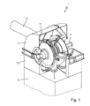
- Figure 1 shows a first embodiment of a claimed low-pressure steam turbine 1, comprising an inner casing 3 that is often made of cast iron. Inside the partially cut away inner casing 3 is a rotor 5 can be seen.
- the exhaust hood 7 may comprise an upper shell assembly 7.1 and a lower-base shell assembly 7.2.
- the lower-base shell assembly 7.2 is open at its bottom and connected to a low-pressure (LP) exhaust 9. Since the main condensing system is not part of the claimed invention, no details of the main condensing system are shown in figure 1 .
- LP low-pressure
- the exhaust hood 7 with its upper shell assembly 7.1 and its lower-base shell assembly 7.2 is a welded construction.
- the claimed low-pressure steam turbine has at least one exhaust steam opening 11 for example in the upper shell assembly 7.1.
- This exhaust steam opening 11 is connected with a radial exhaust steam duct line 13.
- This radial exhaust steam duct connection 13 is connected to an additional or second condensing system (not shown in figure 1 ). Consequently, it is possible to condense the LP- steam from the turbine either in the main condensing system or in the additional condensing system.
- This flexibility is very advantageous, in case the main condensing system 9 has to be operated under certain restrictions for example a reduced cooling water supply.
- the exhaust hood 7 is a welded construction, it is possible to install the exhaust steam duct 13 at existing exhaust hoods by opening the exhaust hood 7 for a further exhaust steam opening 11 and to weld the additional exhaust steam duct connection 13 onto for example the upper shell assembly 7.1.
- the claimed invention can be realized not only in new designs and constructions of low-pressure steam turbines, but is a retrofit-solution for existing steam power plants, that may lead to an equal or improved electricity output, even if the capacity of the main condensing system is reduced due to cooling water restrictions.
- Figure 2 shows a rather similar embodiment of the claimed invention.
- the main difference between the embodiments of figures 1 and 2 is that the exhaust steam duct is not radial, but axial compared to the axis of rotation of the rotor 5.
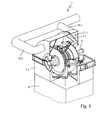
- the third embodiment of the claimed invention shown in figure 3 comprises a double-line axial exhaust steam duct connection 30.
- the third embodiment shows a double-line' axial exhaust steam duct connection 13. Consequently, the exhaust hood 7 comprises two exhaust steam openings, from which only one (cf. reference no. 11.1) can be seen.
- the exhaust steam openings 11 and the exhaust steam ducts 13 can be arranged in several positions, depending on the space that is available and the amount of low-pressure steam that has to be extracted via the exhaust steam openings 11 and the capacity of the additional condenser. This means that the embodiments shown in figures 1 to 3 are suitable for retrofit of existing low-pressure turbines.
- a comparable effect can be achieved by using the extracting points at the inner casing 3 of a low-pressure steam turbine and leading the steam extracted from this extraction point to an additional condensing system.
- This embodiment does not need any alterations concerning the low-pressure steam turbine, if such an extraction point is already existing. For this reason, no embodiment of this type of low-pressure turbine is shown.
- the airtight interface 11, 13, 27 and 29 between the existing turbine 1 and the retrofitted additional condensing system 25, may be operated at the same or a different pressure level than the existing main condensing system 17.
- FIG 4 is a schematic illustration of an embodiment of the claimed invention configured to supply energy to a power grid.
- the power plant is a multi-pressure single-shaft power plant and includes a steam turbine assembly and a generator.
- the generator is not shown in figure 4 as well as the high-pressure and the intermediate-pressure turbines of the steam turbine assembly.
- the low-pressure steam turbine 1 is shown. It is supplied with low-pressure steam by an overflow pipe 15. This overflow pipe 15 connects the intermediate pressure turbine (not shown) with the low-pressure steam turbine 1.
- the low-pressure steam turbine consists of an inner casing 3 and exhaust hood 7 that is connected via the low-pressure exhaust 9 with a main condensing system 17.
- the main condensing system 17 may be of the surface condenser-type that is connected to the cooling water pipes 18 with a cooling system, preferably a wet cooling system, for example a cooling tower. Downstream of the main condensing system 17 are several condensate pumps 21 that deliver the condensed steam to a condensate pipe 23.
- the turbine is supplied with steam by the overflow pipe 15 that is connected to the inner casing 3.
- the steam with a pressure of approximately 0,03 bar to 0,06 bar enters the exhaust hood 7 and under normal ambient and operating conditions leaves the exhaust 7 hood via the low-pressure exhaust 9 into the main condensing system 17.
- an additional condensing system 25 is provided.
- the jet condenser of the additional condensing system 25 is connected to the exhaust hood 7 by means of the exhaust steam duct 13.
- the control valve 27 may be of the butterfly valve-type and is airtight, if closed.
- the jet condenser of the additional condensing system 25 is preferably connected to a dry cooling system, because the main reason for installing the additional condensing system 25 is the shortage of cooling water for the wet cooling system of the main condensing system 17. Therefore, in most cases it does not make sense to connect the additional condensing system 25 with a second wet cooling system. This may make sense, if there is a second heat sink with different temperature and pressure levels and/or different purity of the cooling water and therefore under some operating conditions this heat sink cannot be used for the main condensing system 17.
- the jet condenser 25 is connected to condensate pumps 31 and cooling water pumps 33.
- the condensate pumps 31 deliver the condensed water into the second condensate pipe 35, which is connected to the first condensate pipe 33. This connection is not shown in figure 4 .
- the additional condensing system 25 is supplied with cold cooling water via cooling water pipe 37.1.
- the warm cooling water is delivered to the (dry) cooling system (not shown) of the additional condensing system 25 via cooling water pipe 37.2.
- FIG 5 a slightly different embodiment of the claimed invention is shown.
- the reference numbers are similar, if similar components are concerned.
- the inner casing 3 of the low-pressure turbine 1 has two extraction points 39 for steam that is not expanded completely.
- This being embodiment requires modifications of the inner casing and the outer casing/the exhaust hood 7.
- the completely expanded steam will be delivered to the main condensing system 17 via the low-pressure exhaust 9.
- a part of the steam that enters the turbine via the overflow pipe 15 can be extracted from the low-pressure turbine 1 via the extracting points 39 and fed into the exhaust steam duct 13.
- this steam is condensed in the additional condensing system 25 and fed via the second condensate pipe 35 into water/steam circuit of the steam power plant.
- the pressure of the steam that flows through the exhaust steam duct 13 is higher than the pressure of the completely expanded steam that flows through the low-pressure exhaust 9 into the main condensing system 17.
- the condensing temperature in the additional condensing system 25 is higher than in the main condensing system 17.
- the inner casing 3 and the outer casing 7 have to be modified by installing extraction points 39 and one or more openings 11 for the steam duct 13.
- the pressure stage, to which the additional heat sink shall be connected, will be chosen considering requirements of the individual power station.
- the additional cooling system connected to at least one LP cylinder will be of non-evaporating type.
- the main benefit in this context would be, that an additional condensing system would allow to override existing load restrictions for a certain cooling water consumption.
- the described solution maintains, or even improves the operation flexibility of the plant.
- the additional condensing system 25 can be taken out of service without compromising the plant performance compared to the status prior to the modification. E.g. when sufficient make-up water for the main condensing system is available, the additional condensing system could be taken out of service and the plant would return to its original operating parameters.
- the pressure stage, to which the additional heat sink is connected could be chosen freely which allows optimizing the cost-benefit ratio, since the required heat exchanger surface is reduced with higher extraction pressure.
- the connected exhaust steam duct 13 can be designed according to the environmental requirements taking into consideration pressure loss minimization.
- the additional condensing system 25 may be connected with one or more LP -turbines 1.
- the condenser technology of the additional condensing system 25 can follow all possible functional principles but will almost certainly have to have a non-evaporative heat sink, when the purpose is to reduce the cooling water consumption.
- the additional condensing system 25 could be placed in any location, but preferably close to the LP-turbine 1 to keep pressure losses in the steam ducts low.
- the condensate as it is produced in the additional condensing system 25, will be fed back into the existing water steam cycle at the appropriate tapping point.
- the interconnection of the LP-turbine and the new heat sink can be carried out in multiple ways and will depend on the space situation of the individual site as well as on the pressure level, where steam shall be extracted.
- the steam duct can be optimized and designed to the best economic and thermodynamic parameters with the boundary conditions of the individual project.
- the described system consists of the following main components:
- the claim includes the installation of any kind of additional heat sink to the low-pressure turbine (exhaust or extraction)., , e.g. evaporative -, non-evaporative cooling, once through cooling, etc. with the appropriate condenser, e.g. surface tube condenser, jet condenser, air cooled condenser, etc..
- the appropriate condenser e.g. surface tube condenser, jet condenser, air cooled condenser, etc.
Landscapes
- Engineering & Computer Science (AREA)
- Mechanical Engineering (AREA)
- General Engineering & Computer Science (AREA)
- Chemical & Material Sciences (AREA)
- Combustion & Propulsion (AREA)
- Engine Equipment That Uses Special Cycles (AREA)
Abstract
A low-pressure turbine and a steam power plant with a low-pressure turbine (1) is suggested that is connected to an additional condensing system (25), thus allowing to maintain the electric output at a high level, even if the main condensing system (17) has a reduced capacity due to cooling water restrictions.
Description
- The claimed invention is related to a low-pressure steam turbine and a steam power plant comprising a low-pressure steam turbine that is connected to a condensing system. From
US 2005/0063821 A1 an example for such a steam power plant is known.Figure 1 of this publication and its description explain in detail the process of a steam power plant. For this reason, the explanation of the process of producing electricity by means of a steam power plant is incorporated by reference into this application. - In existing designs of low-pressure turbines the steam exhaust at the end of the steam path is typically connected to a singular heat sink for every exhaust hood where the condensing process takes place. This solution is appropriate when the power plant is being operated as per the original design parameters and sufficient cooling capacity for condensing the steam is available.
- Today there is a growing need to adapt the operating regime of existing power plants to changing boundary conditions, resulting from e.g. climate change or environmental restrictions. Especially seasonal restricted water supply and a shortage in cooling water make-up resulting thereof, has led for power plants to forced load reductions.
- When the capacity of the existing condensing process is not sufficient because of insufficient flow of make-up water, an additional condensing system has to be implemented to handle the entropy flow when the power output shall not be reduced.
- The additional cooling system could be installed either into the existing cooling water cycle or could directly be connected to the water steam cycle.
- Shall the existing system be off loaded, technically only a system will be suitable, that is operating at the same or a lower condensing pressure, compared to the existing system. This means, that it ought to be operated with a working medium, that is cooler than the existing cooling water system or with a very small cooling range.
- Very often the arrangement of the second condenser is very challenging, because of insufficient space next to the existing condenser.
- Consequently, it is an object of the claimed invention to provide a low-pressure turbine and a steam power plant with an optimized cold end of the steam turbine resulting in an unload of the existing condenser and in enabling the power plant to maintain a high electricity output, even if the cooling capacity of the regular condenser is of restricted capability due to shortage of cooling water.
- A further object of the invention is to reduce the cooling water consumption of the first condensing system.
- These objects are achieved by a low-pressure turbine of a steam power plant comprising an inner casing and an exhaust hood, wherein the exhaust hood is connected to a condenser, by providing at least one further steam outlet allowing to supply the expanded steam from inside the exhaust hood to a second condensing system, thereby reducing the cooling load of the first condenser.
- The claimed low-pressure turbine is connected to two condensing systems. One of them is the "regular" or main condensing system that is more or less directly connected to the exhaust hood of the low-pressure turbine. The second or additional condensing system is almost certainly a dry cooling system.
- This arrangement improves the operation flexibility of the steam power plant, since for example in summer, when the ambient temperature is high and only a small amount of cooling water is available, the second condensing system can be activated and consequently the electricity output of the steam power plant is not reduced, although only a small amount of cooling water is available. As soon as sufficient make-up water for the condensing system is available, the additional condensing system can be taken out of service and the plant can return to its original operating parameters.
- A main advantage of the low-pressure turbine according to
claim 1 is that, since the exhaust hood normally is a welded construction, the retrofit of an already installed low-pressure turbine is possible. This retrofit comprises adding a further exhaust steam opening for example in the upper shell of the exhaust hood and connect this further exhaust steam opening with the additional condensing system. - A further advantageous embodiment of this low-pressure turbine is characterized in that the inner casing of the low-pressure turbine comprises at least one extraction point for steam. This means the claimed low-pressure turbine may be used as a bleeding turbine, a tapped turbine or an extraction turbine.
- The claimed invention is also achieved by a low-pressure turbine of a steam power plant, comprising an inner casing and an exhaust hood, wherein the inner casing comprises at least one extraction point for steam, characterized in that at least one extraction point is connected to a second condensing system. This arrangement allows the use of at least one steam extraction point of the low-pressure turbine to extract some of the partially expanded steam at a pressure of approximately 200 mbar to 1000 mbar and condense this extracted steam in the additional condensing system. Consequently, the main condensing system is relieved and the cooling water demand of the main condenser is reduced.
- To control the amount of steam that is condensed in the second condensing system between the further exhaust steam opening in the exhaust hood and/or the at least one extraction point of the inner casing a control valve and/or a non-return valve is installed.
- A further main advantage of the low-pressure turbine according to
claim 3 consists in the fact that an existing extraction point can alternatively be used for extracting steam for heating purposes or to reduce the cooling load of the main condensing system - for example in summer when no heat requirements exist - by exhausting steam and having this extracted steam condensed in a second condensing system. - These advantages can also be realized with the steam power plants according to
claim 5 or 6. Further advantages are disclosed in the drawings, their descriptions and the claims. - The drawings show
- Figure 1
- an embodiment of a claimed low-pressure turbine with one further exhaust steam opening,
- figure 2
- a second embodiment with a single-line exhaust steam duct connection,
- figure 3
- a low-pressure turbine with a double-line exhaust steam duct connection,
- figure 4
- a block diagram of a steam power plant with a low-pressure steam turbine, a main condensing system and an additional condensing system with a single-line axial exhaust steam duct connection and
- figure 5
- a low-pressure turbine using two extraction points of the inner casing for extraction of steam to the additional condensing system.
-
Figure 1 shows a first embodiment of a claimed low-pressure steam turbine 1, comprising aninner casing 3 that is often made of cast iron. Inside the partially cut awayinner casing 3 is arotor 5 can be seen. Theexhaust hood 7 may comprise an upper shell assembly 7.1 and a lower-base shell assembly 7.2. The lower-base shell assembly 7.2 is open at its bottom and connected to a low-pressure (LP)exhaust 9. Since the main condensing system is not part of the claimed invention, no details of the main condensing system are shown infigure 1 . - As can be seen from
figure 1 , theexhaust hood 7 with its upper shell assembly 7.1 and its lower-base shell assembly 7.2 is a welded construction. The claimed low-pressure steam turbine has at least one exhaust steam opening 11 for example in the upper shell assembly 7.1. Thisexhaust steam opening 11 is connected with a radial exhauststeam duct line 13. This radial exhauststeam duct connection 13 is connected to an additional or second condensing system (not shown infigure 1 ). Consequently, it is possible to condense the LP- steam from the turbine either in the main condensing system or in the additional condensing system. This flexibility is very advantageous, in case themain condensing system 9 has to be operated under certain restrictions for example a reduced cooling water supply. This being the case a part of the steam exhausted by the low-pressure turbine 1 can be condensed in the additional condensing system resulting in a load reduction of the main condensing system. Consequently, the electricity generation of the steam power plant can be maintained at a high level, even if themain condenser 9 operates at a reduced performance. - Since the
exhaust hood 7 is a welded construction, it is possible to install theexhaust steam duct 13 at existing exhaust hoods by opening theexhaust hood 7 for a furtherexhaust steam opening 11 and to weld the additional exhauststeam duct connection 13 onto for example the upper shell assembly 7.1. This means that the claimed invention can be realized not only in new designs and constructions of low-pressure steam turbines, but is a retrofit-solution for existing steam power plants, that may lead to an equal or improved electricity output, even if the capacity of the main condensing system is reduced due to cooling water restrictions. -
Figure 2 shows a rather similar embodiment of the claimed invention. The main difference between the embodiments offigures 1 and2 is that the exhaust steam duct is not radial, but axial compared to the axis of rotation of therotor 5. - The third embodiment of the claimed invention shown in
figure 3 comprises a double-line axial exhaust steam duct connection 30. The third embodiment shows a double-line' axial exhauststeam duct connection 13. Consequently, theexhaust hood 7 comprises two exhaust steam openings, from which only one (cf. reference no. 11.1) can be seen. - By looking at the three embodiments shown in
figure 1 ,2 and3 it is apparent that theexhaust steam openings 11 and theexhaust steam ducts 13 can be arranged in several positions, depending on the space that is available and the amount of low-pressure steam that has to be extracted via theexhaust steam openings 11 and the capacity of the additional condenser. This means that the embodiments shown infigures 1 to 3 are suitable for retrofit of existing low-pressure turbines. - A comparable effect can be achieved by using the extracting points at the
inner casing 3 of a low-pressure steam turbine and leading the steam extracted from this extraction point to an additional condensing system. This embodiment does not need any alterations concerning the low-pressure steam turbine, if such an extraction point is already existing. For this reason, no embodiment of this type of low-pressure turbine is shown. - The
airtight interface turbine 1 and the retrofittedadditional condensing system 25, may be operated at the same or a different pressure level than the existingmain condensing system 17. -
Figure 4 is a schematic illustration of an embodiment of the claimed invention configured to supply energy to a power grid. In this exemplary embodiment, the power plant is a multi-pressure single-shaft power plant and includes a steam turbine assembly and a generator. The generator is not shown infigure 4 as well as the high-pressure and the intermediate-pressure turbines of the steam turbine assembly. Infigure 4 only the low-pressure steam turbine 1 is shown. It is supplied with low-pressure steam by anoverflow pipe 15. Thisoverflow pipe 15 connects the intermediate pressure turbine (not shown) with the low-pressure steam turbine 1. The low-pressure steam turbine consists of aninner casing 3 andexhaust hood 7 that is connected via the low-pressure exhaust 9 with amain condensing system 17. - The
main condensing system 17 may be of the surface condenser-type that is connected to the cooling water pipes 18 with a cooling system, preferably a wet cooling system, for example a cooling tower. Downstream of themain condensing system 17 are several condensate pumps 21 that deliver the condensed steam to acondensate pipe 23. - Referring again to the low-
pressure steam turbine 1, even from the block diagram it can be seen that the turbine is supplied with steam by theoverflow pipe 15 that is connected to theinner casing 3. After expansion of the steam in the low-pressure turbine 1 the steam with a pressure of approximately 0,03 bar to 0,06 bar, enters theexhaust hood 7 and under normal ambient and operating conditions leaves theexhaust 7 hood via the low-pressure exhaust 9 into themain condensing system 17. - In addition to that
main condensing system 17 anadditional condensing system 25 is provided. The jet condenser of theadditional condensing system 25 is connected to theexhaust hood 7 by means of theexhaust steam duct 13. Between theadditional condensing system 25 and theexhaust hood 7 there is acontrol valve 27 and a backflow-valve 29. Thecontrol valve 27 may be of the butterfly valve-type and is airtight, if closed. - The jet condenser of the
additional condensing system 25 is preferably connected to a dry cooling system, because the main reason for installing theadditional condensing system 25 is the shortage of cooling water for the wet cooling system of themain condensing system 17. Therefore, in most cases it does not make sense to connect theadditional condensing system 25 with a second wet cooling system. This may make sense, if there is a second heat sink with different temperature and pressure levels and/or different purity of the cooling water and therefore under some operating conditions this heat sink cannot be used for themain condensing system 17. - The
jet condenser 25 is connected to condensate pumps 31 and cooling water pumps 33. The condensate pumps 31 deliver the condensed water into thesecond condensate pipe 35, which is connected to thefirst condensate pipe 33. This connection is not shown infigure 4 . Theadditional condensing system 25 is supplied with cold cooling water via cooling water pipe 37.1. The warm cooling water is delivered to the (dry) cooling system (not shown) of theadditional condensing system 25 via cooling water pipe 37.2. - As can be seen from
figure 4 , by opening theexhaust hood 7 and connecting an additionalexhaust steam duct 13 and installing anadditional condensing system 25, it is possible to relieve the load of themain condensing system 17 without reducing the steam flow through the steam power plant and consequently without reducing the electric output of the steam power plant. - Since the only connection between the
additional condensing system 25 and the steam power plant, merely no restrictions with regard to space available, and the place where theexhaust steam duct 13 is attached to theexhaust hood 7 exist. This means that the claimed concept can be realized even under difficult conditions, as far as the available space is concerned. Since theexhaust hood 7 is normally a welded construction, it is also possible to install theadditional condensing system 25 and theexhaust steam duct 13 as a retrofit or upgrading of existing steam power plants. - In
figure 5 a slightly different embodiment of the claimed invention is shown. The reference numbers are similar, if similar components are concerned. As can be seen fromfigure 5 , theinner casing 3 of the low-pressure turbine 1 has twoextraction points 39 for steam that is not expanded completely. This being embodiment requires modifications of the inner casing and the outer casing/theexhaust hood 7. - The completely expanded steam will be delivered to the
main condensing system 17 via the low-pressure exhaust 9. In case the capability of themain condensing system 17 is reduced, for example due to cooling water restrictions, a part of the steam that enters the turbine via theoverflow pipe 15 can be extracted from the low-pressure turbine 1 via the extractingpoints 39 and fed into theexhaust steam duct 13. - Similar to the embodiment shown in
figure 4 this steam is condensed in theadditional condensing system 25 and fed via thesecond condensate pipe 35 into water/steam circuit of the steam power plant. In this case the pressure of the steam that flows through theexhaust steam duct 13 is higher than the pressure of the completely expanded steam that flows through the low-pressure exhaust 9 into themain condensing system 17. This means that the condensing temperature in theadditional condensing system 25 is higher than in themain condensing system 17. This allows to use a heat sink for the additional condensing system that has a higher temperature than the heat sink for themain condensing system 17. Therefore, in some cases it is possible to use not only a dry cooling system, but also a wet cooling system using a different heat sink for theadditional condensing system 25. Also in this case the flexibility with regard to the connection of the additional condensing system is rather high. In case low-pressure turbine already is equipped with the extraction points 39, theexhaust steam duct 13 is necessary to connect the LP-turbine with the additional condensing system. - In case the low-pressure turbine is not equipped with extraction points, the
inner casing 3 and theouter casing 7 have to be modified by installingextraction points 39 and one ormore openings 11 for thesteam duct 13. - The flexibility of the claimed invention is rather high for the following reasons:
- The pressure stage, to which the additional heat sink shall be connected, will be chosen considering requirements of the individual power station.
- With the load reduction of the existing condenser, it is also possible to maximize the power output with a limited consumption of cooling water make up.
- When the target is to reduce the cooling water consumption, the additional cooling system connected to at least one LP cylinder will be of non-evaporating type. The main benefit in this context would be, that an additional condensing system would allow to override existing load restrictions for a certain cooling water consumption.
- The described solution maintains, or even improves the operation flexibility of the plant. The
additional condensing system 25 can be taken out of service without compromising the plant performance compared to the status prior to the modification. E.g. when sufficient make-up water for the main condensing system is available, the additional condensing system could be taken out of service and the plant would return to its original operating parameters. - When the LP -
turbine 1 should be chocked or not sufficient condensing capacity should be available, the total MW output level could even be increased when more condensing capacity is made available. - The pressure stage, to which the additional heat sink is connected, could be chosen freely which allows optimizing the cost-benefit ratio, since the required heat exchanger surface is reduced with higher extraction pressure.
- With the upper shell assembly 7.1 being previewed as terminal point of the
exhaust steam duct 13, usually there is enough space available for the steam duct routing. The connectedexhaust steam duct 13 can be designed according to the environmental requirements taking into consideration pressure loss minimization. - In order to facilitate the necessary connection for the
steam duct 13, in essence only the modification of the top halfinner casing 3 will be necessary, when an existing extraction pressure stage is used. In some cases it is necessary to modify the top and the bottom half of theinner casing 3, since for condensating purposes more steam is extracted from the turbine than for conventional use of the extracted steam, for example for heating purposes. - Should the LP-exhaust be connected to the new heat sink, only a modification to the outer casing will be required.
- With an appropriate steam ducting the
additional condensing system 25 may be connected with one or more LP -turbines 1. The condenser technology of theadditional condensing system 25 can follow all possible functional principles but will almost certainly have to have a non-evaporative heat sink, when the purpose is to reduce the cooling water consumption. - The
additional condensing system 25 could be placed in any location, but preferably close to the LP-turbine 1 to keep pressure losses in the steam ducts low. - The condensate as it is produced in the
additional condensing system 25, will be fed back into the existing water steam cycle at the appropriate tapping point. - The interconnection of the LP-turbine and the new heat sink can be carried out in multiple ways and will depend on the space situation of the individual site as well as on the pressure level, where steam shall be extracted.
- The figures are demonstrating the flexibility of the proposed solution with regard to the implementation of the additional suction line and condensing system.
- It is also possible to choose from different extraction pressure levels.
- In general the steam duct can be optimized and designed to the best economic and thermodynamic parameters with the boundary conditions of the individual project.
- The described system consists of the following main components:
- Modified exhaust casing with and without a modification to the inner casing
- Steam exhaust duct
- Compensation elements
- Air tight connection to exhaust casing
- Control butterfly valve (air tight when closed)
- Non-return valve and
- Condensate extraction line
- As shown in
figures 1-6 above the claim includes the installation of any kind of additional heat sink to the low-pressure turbine (exhaust or extraction)., , e.g. evaporative -, non-evaporative cooling, once through cooling, etc. with the appropriate condenser, e.g. surface tube condenser, jet condenser, air cooled condenser, etc..
Claims (7)
- Low-pressure turbine (1) of a steam power plant comprising an inner casing (3) and an exhaust hood (7), wherein the outer casing (7) is connected to a main condensing system (17), characterized in, that the exhaust hood (7) comprises at least one further exhaust steam-opening (11) that is connected to an additional condensing system (25).
- Low-pressure turbine (1) according to claim 1, characterized in, that the inner casing (3) comprises at least one extraction point (39) for steam condensation enthalpy emission.
- Low-pressure turbine (1) of a steam power plant comprising an inner casing (3), wherein the inner casing (3) comprises at least one extraction point (39) for steam, characterized in, that at least one extraction point (39) is connected to an additional condensing system (25).
- Low-pressure turbine (1) according to claim 3, characterized in, that an exhaust hood (7) is connected to main condensing system (17).
- Low-pressure turbine (1) according to one of the foregoing claims, characterized in, that downstream of the at least one further exhaust steam-opening (11) and/or downstream of the at least one extraction point (39) and upstream of the additional condensing system (25) a control valve (27), preferably a butterfly valve, and/or a non-return valve (29) is installed.
- Steam power plant with a low-pressure turbine (1) and a main condensing system (17), characterized in, that the low-pressure turbine (1) is a low-pressure turbine according to one of the foregoing claims and that the steam power plant comprises an additional condensing system (25).
- Steam power according to claim 6, characterized in, that the second condensing system (25) is of evaporative cooling, non-evaporative cooling and/or once through cooling type.
Priority Applications (4)
| Application Number | Priority Date | Filing Date | Title |
|---|---|---|---|
| EP20100003311 EP2372111A1 (en) | 2010-03-27 | 2010-03-27 | Low pressure turbine with two independent condensing systems |
| US13/637,831 US20130213042A1 (en) | 2010-03-27 | 2011-03-14 | Low pressure turbine with two independent condensing systems |
| PCT/EP2011/053782 WO2011120786A2 (en) | 2010-03-27 | 2011-03-14 | Low pressure turbine with two independent condensing systems |
| AU2011234758A AU2011234758A1 (en) | 2010-03-27 | 2011-03-14 | Low pressure turbine with two independent condensing systems |
Applications Claiming Priority (1)
| Application Number | Priority Date | Filing Date | Title |
|---|---|---|---|
| EP20100003311 EP2372111A1 (en) | 2010-03-27 | 2010-03-27 | Low pressure turbine with two independent condensing systems |
Publications (1)
| Publication Number | Publication Date |
|---|---|
| EP2372111A1 true EP2372111A1 (en) | 2011-10-05 |
Family
ID=43034152
Family Applications (1)
| Application Number | Title | Priority Date | Filing Date |
|---|---|---|---|
| EP20100003311 Withdrawn EP2372111A1 (en) | 2010-03-27 | 2010-03-27 | Low pressure turbine with two independent condensing systems |
Country Status (4)
| Country | Link |
|---|---|
| US (1) | US20130213042A1 (en) |
| EP (1) | EP2372111A1 (en) |
| AU (1) | AU2011234758A1 (en) |
| WO (1) | WO2011120786A2 (en) |
Cited By (1)
| Publication number | Priority date | Publication date | Assignee | Title |
|---|---|---|---|---|
| US9752461B2 (en) | 2013-02-05 | 2017-09-05 | General Electric Technology Gmbh | Steam power plant with a second low-pressure turbine and an additional condensing system |
Families Citing this family (5)
| Publication number | Priority date | Publication date | Assignee | Title |
|---|---|---|---|---|
| JP6087803B2 (en) * | 2013-12-25 | 2017-03-01 | 三菱重工業株式会社 | Steam turbine |
| DE102015213257A1 (en) * | 2015-07-15 | 2017-01-19 | Siemens Aktiengesellschaft | Abdampfgehäuse for a turbine, turbine frame, turbine housing and mounting system |
| EP3301263B1 (en) * | 2016-10-03 | 2019-11-27 | General Electric Technology GmbH | Turbine exhaust structure of particular design |
| JP6884660B2 (en) | 2017-07-13 | 2021-06-09 | 三菱パワー株式会社 | Steam turbine system |
| SE547323C2 (en) * | 2023-02-10 | 2025-07-01 | Climeon Ab | Thermodynamic system comprising a pump assembly |
Citations (4)
| Publication number | Priority date | Publication date | Assignee | Title |
|---|---|---|---|---|
| GB105933A (en) * | 1916-02-04 | 1917-05-04 | Karl Baumann | Improvements in or relating to Steam Turbines. |
| US3973404A (en) * | 1974-01-23 | 1976-08-10 | Hitachi, Ltd. | Low pressure turbine installation |
| US5779435A (en) * | 1995-06-30 | 1998-07-14 | Asea Brown Boveri Ag | Low-pressure steam turbine |
| US6244035B1 (en) * | 1997-10-15 | 2001-06-12 | Siemens Aktiengesellschaft | Gas and steam-turbine plant and method of operating the plant |
Family Cites Families (11)
| Publication number | Priority date | Publication date | Assignee | Title |
|---|---|---|---|---|
| US1551569A (en) * | 1925-09-01 | Sylvania | ||
| BE524202A (en) * | 1952-11-20 | |||
| GB754580A (en) * | 1953-05-20 | 1956-08-08 | Westinghouse Electric Int Co | Improvements in or relating to elastic fluid turbines such as steam turbines |
| GB1024844A (en) * | 1962-02-12 | 1966-04-06 | Pametrada | Improvements in or relating to steam turbines |
| US3820334A (en) * | 1972-07-28 | 1974-06-28 | Transelektro Magyar Villamossa | Heating power plants |
| SE464773B (en) * | 1989-10-04 | 1991-06-10 | Abb Stal Ab | INSULATION OF TURBINE EQUIPMENT IN THE ENVIRONMENT OF WATER ENVIRONMENT |
| BR9405757A (en) * | 1993-12-10 | 1995-11-28 | Cabot Corp | Process to increase combined cycle installation capacity and efficiency and liquefied natural gas combined cycle installation system |
| JP2000291403A (en) * | 1999-04-02 | 2000-10-17 | Toshiba Corp | Steam turbine |
| US6971842B2 (en) | 2003-09-22 | 2005-12-06 | General Electric Company | Low pressure steam turbine exhaust hood |
| DE102006027237A1 (en) * | 2005-06-14 | 2006-12-28 | Alstom Technology Ltd. | Steam turbine for a power plant has guide blade rows that are arranged on a single blade ring which is in turn arranged in the inner casing |
| JP5180652B2 (en) * | 2008-03-31 | 2013-04-10 | 三菱重工業株式会社 | Steam turbine casing structure |
-
2010
- 2010-03-27 EP EP20100003311 patent/EP2372111A1/en not_active Withdrawn
-
2011
- 2011-03-14 WO PCT/EP2011/053782 patent/WO2011120786A2/en not_active Ceased
- 2011-03-14 US US13/637,831 patent/US20130213042A1/en not_active Abandoned
- 2011-03-14 AU AU2011234758A patent/AU2011234758A1/en not_active Abandoned
Patent Citations (4)
| Publication number | Priority date | Publication date | Assignee | Title |
|---|---|---|---|---|
| GB105933A (en) * | 1916-02-04 | 1917-05-04 | Karl Baumann | Improvements in or relating to Steam Turbines. |
| US3973404A (en) * | 1974-01-23 | 1976-08-10 | Hitachi, Ltd. | Low pressure turbine installation |
| US5779435A (en) * | 1995-06-30 | 1998-07-14 | Asea Brown Boveri Ag | Low-pressure steam turbine |
| US6244035B1 (en) * | 1997-10-15 | 2001-06-12 | Siemens Aktiengesellschaft | Gas and steam-turbine plant and method of operating the plant |
Cited By (1)
| Publication number | Priority date | Publication date | Assignee | Title |
|---|---|---|---|---|
| US9752461B2 (en) | 2013-02-05 | 2017-09-05 | General Electric Technology Gmbh | Steam power plant with a second low-pressure turbine and an additional condensing system |
Also Published As
| Publication number | Publication date |
|---|---|
| AU2011234758A1 (en) | 2012-11-22 |
| US20130213042A1 (en) | 2013-08-22 |
| WO2011120786A2 (en) | 2011-10-06 |
| WO2011120786A3 (en) | 2011-11-24 |
Similar Documents
| Publication | Publication Date | Title |
|---|---|---|
| US6968696B2 (en) | Part load blade tip clearance control | |
| US8387388B2 (en) | Turbine blade | |
| WO2011120786A2 (en) | Low pressure turbine with two independent condensing systems | |
| EP3011146B1 (en) | Steam power plant turbine and control method for operating at low load | |
| US20080304954A1 (en) | Highly Supercharged Gas Turbine Generating System | |
| US8172521B2 (en) | Compressor clearance control system using turbine exhaust | |
| US8152457B2 (en) | Compressor clearance control system using bearing oil waste heat | |
| US8387356B2 (en) | Method of increasing power output of a combined cycle power plant during select operating periods | |
| US12104506B2 (en) | Plant and operation method therefor | |
| US20090136337A1 (en) | Method and Apparatus for Improved Reduced Load Operation of Steam Turbines | |
| JP5916053B2 (en) | System with feed water heater that extracts heat from a low pressure steam turbine | |
| US11408339B2 (en) | Steam turbine system and combined cycle plant | |
| CN106460545B (en) | Gas Turbine Generator Cooling | |
| US9752461B2 (en) | Steam power plant with a second low-pressure turbine and an additional condensing system | |
| US11300011B1 (en) | Gas turbine heat recovery system and method | |
| CA2828449C (en) | Combined cycle power plant | |
| US20160146060A1 (en) | Method for operating a combined cycle power plant | |
| JP2002129907A (en) | Ground steam system for steam turbine | |
| EP3040525B1 (en) | Multi stage steam turbine for power generation | |
| Kloss-Grote et al. | Advanced Steam Turbine Technology for Unique Double Reheat Steam Power Plant Layout | |
| Barinberg et al. | Steam turbines of the Ural Turbine Works for advanced projects of combined-cycle plants | |
| Simoyu et al. | Effect of Operating Conditions of a T-250/300-240 Turbine on the Level of Wetness in the Stages of the Low-Pressure Cylinder | |
| Ermolenko et al. | Construction of power-generating gas turbine units with the use of efficient thermal schemes | |
| Radin et al. | Specific features relating to development and operation of steam turbines for combined-cycle plants |
Legal Events
| Date | Code | Title | Description |
|---|---|---|---|
| PUAI | Public reference made under article 153(3) epc to a published international application that has entered the european phase |
Free format text: ORIGINAL CODE: 0009012 |
|
| AK | Designated contracting states |
Kind code of ref document: A1 Designated state(s): AT BE BG CH CY CZ DE DK EE ES FI FR GB GR HR HU IE IS IT LI LT LU LV MC MK MT NL NO PL PT RO SE SI SK SM TR |
|
| AX | Request for extension of the european patent |
Extension state: AL BA ME RS |
|
| 17P | Request for examination filed |
Effective date: 20120216 |
|
| 17Q | First examination report despatched |
Effective date: 20150427 |
|
| STAA | Information on the status of an ep patent application or granted ep patent |
Free format text: STATUS: THE APPLICATION IS DEEMED TO BE WITHDRAWN |
|
| 18D | Application deemed to be withdrawn |
Effective date: 20150908 |