EP2372027B1 - Facing element for use in a stabilized soil structure - Google Patents
Facing element for use in a stabilized soil structure Download PDFInfo
- Publication number
- EP2372027B1 EP2372027B1 EP10305342A EP10305342A EP2372027B1 EP 2372027 B1 EP2372027 B1 EP 2372027B1 EP 10305342 A EP10305342 A EP 10305342A EP 10305342 A EP10305342 A EP 10305342A EP 2372027 B1 EP2372027 B1 EP 2372027B1
- Authority
- EP
- European Patent Office
- Prior art keywords
- facing
- facing element
- cylindrical core
- fill
- rear face
- Prior art date
- Legal status (The legal status is an assumption and is not a legal conclusion. Google has not performed a legal analysis and makes no representation as to the accuracy of the status listed.)
- Active
Links
Images


Classifications
-
- E—FIXED CONSTRUCTIONS
- E02—HYDRAULIC ENGINEERING; FOUNDATIONS; SOIL SHIFTING
- E02D—FOUNDATIONS; EXCAVATIONS; EMBANKMENTS; UNDERGROUND OR UNDERWATER STRUCTURES
- E02D29/00—Independent underground or underwater structures; Retaining walls
- E02D29/02—Retaining or protecting walls
- E02D29/0225—Retaining or protecting walls comprising retention means in the backfill
- E02D29/0241—Retaining or protecting walls comprising retention means in the backfill the retention means being reinforced earth elements
-
- E—FIXED CONSTRUCTIONS
- E02—HYDRAULIC ENGINEERING; FOUNDATIONS; SOIL SHIFTING
- E02D—FOUNDATIONS; EXCAVATIONS; EMBANKMENTS; UNDERGROUND OR UNDERWATER STRUCTURES
- E02D29/00—Independent underground or underwater structures; Retaining walls
- E02D29/02—Retaining or protecting walls
- E02D29/0225—Retaining or protecting walls comprising retention means in the backfill
-
- E—FIXED CONSTRUCTIONS
- E02—HYDRAULIC ENGINEERING; FOUNDATIONS; SOIL SHIFTING
- E02D—FOUNDATIONS; EXCAVATIONS; EMBANKMENTS; UNDERGROUND OR UNDERWATER STRUCTURES
- E02D29/00—Independent underground or underwater structures; Retaining walls
- E02D29/02—Retaining or protecting walls
- E02D29/025—Retaining or protecting walls made up of similar modular elements stacked without mortar
Definitions
- the present invention relates to a facing element for use in a stabilized soil structure. It also relates to a stabilized soil structure comprising said facing element and to a method for erecting a stabilized soil or reinforced earth structure. This building technique is commonly used to produce structures such as retaining walls, bridge abutments, etc.
- a stabilized soil structure combines a compacted fill, a facing, and reinforcements usually connected to the facing.
- the reinforcements are placed in the soil with a density dependent on the stresses that might be exerted on the structure, the thrust forces of the soil being reacted by the soil-reinforcements friction.
- the invention more particularly concerns the case where the reinforcements are in the form of fill reinforcement strips of synthetic material, for example based on polyester fibers.
- the facing is most often made up of facing elements, as for example in the form of prefabricated concrete elements, such as slabs or blocks, juxtaposed to cover the front face of the structure. There may be horizontal steps on this front face between different levels of the facing, when the structure has one or more terraces.
- the fill reinforcement strips placed in the fill are usually secured to the facing by mechanical connecting members that may take various forms. Once the structure is complete, the reinforcements distributed through the fill transmit high loads, in some cases of up to several tons. Their connection to the facing needs to be robust in order to maintain the cohesion of the whole.
- a facing element comprises a front face and a rear face extending along a longitudinal direction X and an elevation direction Z and a body between said front and rear faces.
- the body of some known facing elements comprises at least a hollow part with an opening on the rear face wherein a cylindrical core is cohesive with the body and arranged at least partly in the hollow part to form an anchoring region for a fill reinforcement strip.
- Patent document US 5,839,855 discloses examples of a facing element where a passage intended to receive a fill reinforcement strip is in the shape of a C within the thickness of the facing element.
- a facing element according to the preamble of claim 1 is further known from FR-A-2868447 .
- the invention thus proposes a facing element for use in a stabilized soil structure
- the facing element comprises a front face and a rear face extending along a longitudinal direction X and an elevation direction Z, a body between said front and rear faces, said body comprising at least a hollow part with an opening on the rear face wherein a cylindrical core is cohesive with the body and arranged at least partly in the hollow part to form an anchoring region for a fill reinforcement strip, wherein the cylindrical core extends substantially parallel to the longitudinal direction X and its cross section, in a plane (Y, Z) perpendicular to the plane (X, Z), consists of two continuous parts separated by a virtual straight line along the direction Z, where the first part has a continuously decreasing size in the direction Y from the virtual straight line to an extremity substantially directed opposite to the rear face of the facing element and the second part has a continuously constant and/or decreasing size from the virtual straight line to an extremity directed to said rear face, and wherein: L 2 ⁇ 1.1 ⁇ x d 1 ; and A
- Said shape and geometric characteristics of the facing element make possible to avoid breaking of the cylindrical core according to a bending mode when being pulled by fill reinforcement strips.
- the inventors have noticed that the cylindrical cores of said facing elements break according to a shearing mode.
- cracks formed in the facing elements of the invention are formed within said body. Those cracks are usually formed in four approximately 45° directions in the (X,Z) plane when fill reinforcement strips pull in the Y direction.
- the inventors have noticed that the breaking energy dissipated within the facing element according to the invention is significantly higher compared to the breaking energy dissipated when the cores break according to a bending mode.
- the invention also relates to a stabilized soil structure, comprising fill reinforcement strips extending through a reinforced zone of a fill situated behind a front face of the structure and a facing placed along said front face and extending along a longitudinal direction X' and an elevation direction Z', the facing comprising at least a facing element according to the present invention and here above disclosed which directions X and Z are arranged so as to coincide with directions X' and z' and fill reinforcement strips being arranged so as to form an open loop around the cylindrical core of the said facing element and said open loop being extended on each side by a segment of the fill reinforcement strip, said segments extending at least partly within the fill.
- a surface of the said strip forming the open loop contacts and presses substantially the whole external periphery of the cross section of the first part of the cylindrical core, and at least a part of the external periphery of the cross section of the second part of the cylindrical core.
- compression load is applied at least partly around the cylindrical core. Said embodiment helps to further improve the pulling resistance of the anchoring region.
- a surface of the strip forming the open loop may contact a surface of the strip forming the pen loop contacts at least 20%, as for example at least 50% of the external periphery of the cross section of the second part of the cylindrical cohesive core.
- the two segments extending the open loop come out of the facing through a same slot. According to another embodiment they come out through two different slots. Said two different slots may be in the same (X, Y) plane or be arranged in two separated (X,Y) planes.
- the invention is also directed to a method for erecting a stabilized soil structure, comprising fill reinforcement strips extending through a reinforced zone of the fill situated behind a front face of the structure, and a facing placed along said front face and extending along a longitudinal direction X' and an elevation direction Z', the reinforcement strips being anchored to the facing in respective anchoring regions comprising the steps of:
- Figure 1 illustrates the application of the invention to the building of a stabilized soil retaining wall or stabilized soil structure before a face 4.
- a compacted fill 1, in which reinforcements 2 are distributed, is delimited on the front side of the structure by a facing 3 formed by juxtaposing facing elements such as prefabricated elements 34 in the form of panels, and on the rear side by the soil against which the stabilized soil structure wall is erected.
- the facing 3 extends along a longitudinal direction X' and an elevation direction Z'.
- the facing 3 may be vertical or inclined.
- the facing elements 34 have a front face 31 and a rear face 32.
- Reinforcements extend through a reinforced zone 11 of the fill situated behind the front face of the structure.
- a zone 12 which does not comprise fill reinforcement strips may be located between the reinforced zone 11 and the face 4.
- the reinforcements 2 comprise synthetic reinforcing members in the form of flexible strips extending in horizontal planes behind the facing 3. These may in particular be fill reinforcement strips based on polyester fibers encased in polyethylene.
- the reinforcement strips 2 are attached in anchoring regions 35 to the prefabricated elements 34 joined together to form the facing 3.
- These elements 34 are typically made of reinforced concrete. In the example shown, they are in the form of panels. They could also have other forms, in particular the form of blocks. According to an example, when the concrete of such an element 34 is cast, one or more reinforcement strips 2 may be installed in the mould to provide the strip-element anchorage. After the concrete has set, each strip has two sections which emerge from the element and are to be installed in the fill material. According to another embodiment, the reinforcement strips are introduced in the anchoring regions 35 after placing the facing elements when erecting the structure.
- the procedure may be as follows:
- the reinforcement strips 2 already placed at the lower levels experience tensioning. This tensioning results from the friction between the strips and the filled material and ensures the reinforcement of the structure. So that the tension is established under good conditions, it is advisable that the strips of one level emerge from their facing elements so that they are all correctly aligned with this level. It is also advisable that they are oriented horizontally as they emerge from the facing, so as to ensure that they do not twist in the filled material.
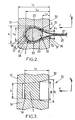
- Figures 2 and 3 are partial cross sectional views of a facing element 34 according to an embodiment of the present invention where the facing element 34 comprises a front face 31 and a rear face 32 extending along a longitudinal direction X and an elevation direction Z, a body between said front and rear faces.
- Said body comprises at least a hollow part 37 with an opening 36 on the rear face 32 wherein a cylindrical core 5 is cohesive with the body and arranged at least partly in the hollow part 37 to form an anchoring region 35 for a fill reinforcement strip.
- the cylindrical core 35 extends substantially parallel to the longitudinal direction X and its cross section, in a plane (Y, Z) perpendicular to the plane (X, Z), consists of two continuous parts 51, 52 separated by a virtual straight line 53 along the direction Z, where the first part 51 has a continuously decreasing size in the direction Y from the virtual straight line 53 to an extremity 54 substantially directed opposite to the rear face 32 of the facing element and the second part 52 has a continuously decreasing size from the virtual straight line 53 to an extremity directed 55 to said rear face 32.
- Resistance of said cylindrical core is even enhanced when L 2 ⁇ 1.3 x d 1 ; and/or when A ⁇ 0.40 x d 1 2 and/or when L 2 /L 1 ⁇ 0.50.
- the cylindrical core 5 and the hollow part 37 are symmetric according to a plane parallel to the (Y,Z) plane passing through the middle of said parts.
- the first part 51 of the cylindrical core cross section is a half-circle and the second part of said core is a half-oval.
- Figure 2 also shows how a fill reinforcement strip 2 can be arranged in the anchoring region 35 of the facing element 34.
- the strip 2 is arranged so as to form an open loop 25 around the cylindrical core 5; said open loop 25 is extended on each side by a segment 26, 27 emerging from the facing element rear face 32 so as to be suitable to extend at least partly within a fill.
- a surface 21 + 22 + 23 of the strip 2 contacts the external surface of the core 5, the surface 21 presses substantially the whole external surface of the periphery of the cross section of the first part 51 of the cylindrical core and the surfaces 22 and 23 press a part of the external surface of the periphery of the cross section of the second part 52 of the cylindrical core 5. It has been demonstrated that the resistance of the cylindrical core is furthermore enhanced thanks to this embodiment.
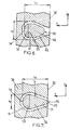
- Figures 4 to 12 show various examples of other embodiments of facing elements according to the present invention.
- the core 5 is tilted from an angle ⁇ compared to the position of the core 5 of figure 2 .
- the extremity 54 substantially directed opposite to the rear face 32 of the facing element, comprises a flat surface 57 located between two curved surfaces.
- the second part 52 comprises an external reverse curved surface 56 from the virtual straight line 53 to the extremity 55.
- the periphery of the cross section of the second part 52 is formed by two substantially straight lines 61 and 62 linked together by curved lines.
- the periphery of the cross section of the second part 52 is formed by a substantially straight line 71 which ends at the rear face 32 of the facing element.
- the extremity of the periphery of the cross section of the second part 52 is formed by a straight line 72 merging with the rear face 32 of the facing element.
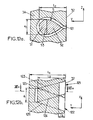
- the periphery of the cross section of the second part 52 is formed by a curved section 81, a reverse curve 82 followed by a substantially straight line 83 substantially parallel to the Y axis.
- the extremity of the said periphery is formed by a straight line 84 merging with the rear face 32 of the facing element.
- the periphery of the cross section of the second part 52 is formed by a curved section 91, a reverse curve 82 followed by a substantially straight line 93 parallel to the Y axis.
- the cross section of the cylindrical core is non symmetric and the lowest part of said cross section is more flat than the upper part.
- the straight line of the extremity 55 of the core can be divided in two thicknesses e90 and e91 where e90 corresponds to the distance between a line according to the Y axis passing through the middle of line 53 and the lower part of the extremity of the cross section, whereas e91 corresponds to the distance between said line and the upper part of the extremity of the cross section.
- e90 corresponds to the distance between a line according to the Y axis passing through the middle of line 53 and the lower part of the extremity of the cross section
- e91 corresponds to the distance between said line and the upper part of the extremity of the cross section.
- the periphery of the cross section of the second part 52 is a rectangle limited by two parallel straight lines 100 parallel to the Y axis and by line 53 and the extremity 55 merging with the rear face 32.
- e3 is equal to e1.
- the cylindrical core 5 protrudes out of the hollow part and a part 111 extents outside of the body of the facing element.
- the core 5 is designed so that the two segments of a fill reinforcement strip extending an open strip loop come out of the facing through two different slots 121, 122.
- the two different slots are arranged in a same plane (X, Y). Lines 123, 124 limit the space for the segment that can emerge from slot 121 and lines 125, 126 limit the space for the segment that can emerge from slot 122.
- the facing element of the invention and related method for erecting a stabilized soil structure are compatible with a large number of configurations of structure, strip lengths, densities for setting up strips, etc..
Landscapes
- Engineering & Computer Science (AREA)
- Structural Engineering (AREA)
- General Life Sciences & Earth Sciences (AREA)
- Mining & Mineral Resources (AREA)
- Paleontology (AREA)
- Civil Engineering (AREA)
- General Engineering & Computer Science (AREA)
- Environmental & Geological Engineering (AREA)
- Life Sciences & Earth Sciences (AREA)
- Pit Excavations, Shoring, Fill Or Stabilisation Of Slopes (AREA)
- Lining And Supports For Tunnels (AREA)
- Piles And Underground Anchors (AREA)
- Bridges Or Land Bridges (AREA)
- Finishing Walls (AREA)
- Soil Working Implements (AREA)
- Road Paving Structures (AREA)
- Coating Apparatus (AREA)
- Catching Or Destruction (AREA)
- Floor Finish (AREA)
Priority Applications (19)
| Application Number | Priority Date | Filing Date | Title |
|---|---|---|---|
| ES10305342T ES2399508T3 (es) | 2010-04-02 | 2010-04-02 | Elemento de paramento para uso en una estructura de suelo estabilizada |
| PL10305342T PL2372027T3 (pl) | 2010-04-02 | 2010-04-02 | Element okładziny licowej do wykorzystania w stabilizowanej ziemnej strukturze |
| EP10305342A EP2372027B1 (en) | 2010-04-02 | 2010-04-02 | Facing element for use in a stabilized soil structure |
| PT103053427T PT2372027E (pt) | 2010-04-02 | 2010-04-02 | Elemento de revestimento para utilização numa estrutura de solo estabilizado |
| JP2013501765A JP5756511B2 (ja) | 2010-04-02 | 2011-03-24 | 安定処理土構造体内において使用するためのフェーシング要素 |
| RU2012146776/03A RU2534285C2 (ru) | 2010-04-02 | 2011-03-24 | Элемент облицовки для использования в конструкции со стабилизированным грунтом |
| CA2794044A CA2794044C (en) | 2010-04-02 | 2011-03-24 | Facing element for use in a stabilized soil structure |
| MYPI2012004404 MY152672A (en) | 2010-04-02 | 2011-03-24 | Facing element for use in a stabilized soil structure |
| AU2011234695A AU2011234695B2 (en) | 2010-04-02 | 2011-03-24 | Facing element for use in a stabilized soil structure |
| CN201180024902.3A CN103038424B (zh) | 2010-04-02 | 2011-03-24 | 用于稳定土结构的面板件 |
| PCT/EP2011/054572 WO2011120873A1 (en) | 2010-04-02 | 2011-03-24 | Facing element for use in a stabilized soil structure |
| PE2012001816A PE20130949A1 (es) | 2010-04-02 | 2011-03-24 | Elemento de revestimiento para su uso en una estructura de suelo estabilizada |
| MX2012011402A MX2012011402A (es) | 2010-04-02 | 2011-03-24 | Elemento de revestimiento para su uso en una estructura de suelo estabilizada. |
| US13/638,566 US8790045B2 (en) | 2010-04-02 | 2011-03-24 | Facing element for use in a stabilized soil structure |
| JO2011114A JO2862B1 (en) | 2010-04-02 | 2011-03-31 | Cladding element for use in stable soil structures |
| IL222065A IL222065A (en) | 2010-04-02 | 2012-09-23 | Front component for use in stabilized land structure |
| CO12171927A CO6612272A2 (es) | 2010-04-02 | 2012-10-01 | Elemento de revstimiento para su uso en una estructura de suelo estabilizada |
| CL2012002763A CL2012002763A1 (es) | 2010-04-02 | 2012-10-02 | Elementos de revestimiento para uso en una estructura de suelo estabilizada porque el elemento de revestimiento comprende una cara frontal y una cara posterior que se extienden a lo largo de una direccion longitudinal x y una direccion de elevacion z; estructura y metodo. |
| HRP20130113AT HRP20130113T1 (hr) | 2010-04-02 | 2013-02-08 | Element obloge za uporabu u stabiliziranoj strukturi tla |
Applications Claiming Priority (1)
| Application Number | Priority Date | Filing Date | Title |
|---|---|---|---|
| EP10305342A EP2372027B1 (en) | 2010-04-02 | 2010-04-02 | Facing element for use in a stabilized soil structure |
Publications (2)
| Publication Number | Publication Date |
|---|---|
| EP2372027A1 EP2372027A1 (en) | 2011-10-05 |
| EP2372027B1 true EP2372027B1 (en) | 2012-11-14 |
Family
ID=42541525
Family Applications (1)
| Application Number | Title | Priority Date | Filing Date |
|---|---|---|---|
| EP10305342A Active EP2372027B1 (en) | 2010-04-02 | 2010-04-02 | Facing element for use in a stabilized soil structure |
Country Status (19)
| Country | Link |
|---|---|
| US (1) | US8790045B2 (pl) |
| EP (1) | EP2372027B1 (pl) |
| JP (1) | JP5756511B2 (pl) |
| CN (1) | CN103038424B (pl) |
| AU (1) | AU2011234695B2 (pl) |
| CA (1) | CA2794044C (pl) |
| CL (1) | CL2012002763A1 (pl) |
| CO (1) | CO6612272A2 (pl) |
| ES (1) | ES2399508T3 (pl) |
| HR (1) | HRP20130113T1 (pl) |
| IL (1) | IL222065A (pl) |
| JO (1) | JO2862B1 (pl) |
| MX (1) | MX2012011402A (pl) |
| MY (1) | MY152672A (pl) |
| PE (1) | PE20130949A1 (pl) |
| PL (1) | PL2372027T3 (pl) |
| PT (1) | PT2372027E (pl) |
| RU (1) | RU2534285C2 (pl) |
| WO (1) | WO2011120873A1 (pl) |
Families Citing this family (9)
| Publication number | Priority date | Publication date | Assignee | Title |
|---|---|---|---|---|
| US20140345220A1 (en) * | 2013-05-24 | 2014-11-27 | Francesco Ferraiolo | Anchoring system for concrete panels in a stabilized earth structure |
| FR3025815B1 (fr) * | 2015-07-07 | 2016-12-30 | Terre Armee Int | Insert de moulage et bloc de parement avec un tel insert |
| WO2017093948A1 (en) * | 2015-12-03 | 2017-06-08 | Fraser Maurice Andrew | Void former |
| WO2019077382A1 (en) | 2017-10-18 | 2019-04-25 | Terre Armee Internationale | REUSABLE CASTING ELEMENT FOR A FACING ELEMENT AND METHOD FOR MANUFACTURING A FACING ELEMENT USING SAID REUSABLE CASTING ELEMENT |
| EP3928833A1 (en) * | 2020-06-24 | 2021-12-29 | Centre Hospitalier Universitaire Vaudois (CHUV) | Device for providing a radiation treatment |
| US12215473B2 (en) | 2021-01-08 | 2025-02-04 | Earth Wall Products, Llc | Method for manufacturing panels for earth retaining wall employing geosynthetic strips |
| US20220220691A1 (en) * | 2021-01-08 | 2022-07-14 | Earth Wall Products, Llc | Mechanically stabilized earth (mse) retaining wall employing geosynthetic strip with plastic pipe(s) around steel rod |
| USD1105900S1 (en) * | 2023-04-26 | 2025-12-16 | Earth Wall Products, Llc | Retaining wall geosynthetic loop connector |
| US12601137B2 (en) | 2023-04-26 | 2026-04-14 | Earth Wall Products, Llc | Mechanically stabilized earth (MSE) retaining wall using geosynthetic reinforcement belt with curvilinear embed apparatus in wall panel |
Family Cites Families (21)
| Publication number | Priority date | Publication date | Assignee | Title |
|---|---|---|---|---|
| SU734348A1 (ru) * | 1977-11-18 | 1980-05-15 | Украинское Отделение Всесоюзного Ордена Ленина Проектно-Изыскательского И Научно-Исследовательского Института "Гидропроект" Им. С.Я.Жука | Способ возведени подпорной стенки |
| DE2753243A1 (de) * | 1977-11-29 | 1979-06-07 | Bayer Ag | Bewehrung von armierten erdbauwerken |
| US4616959A (en) * | 1985-03-25 | 1986-10-14 | Hilfiker Pipe Co. | Seawall using earth reinforcing mats |
| US4824293A (en) * | 1987-04-06 | 1989-04-25 | Brown Richard L | Retaining wall structure |
| SU1596024A1 (ru) * | 1987-07-15 | 1990-09-30 | Грузинский Научно-Исследовательский Институт Гидротехники И Мелиорации | Ограждающа конструкци |
| US4914887A (en) * | 1988-12-12 | 1990-04-10 | Meheen H Joe | Method and apparatus for anchoring backfilled wall structures |
| SU1649043A1 (ru) * | 1989-03-02 | 1991-05-15 | Всесоюзный научно-исследовательский, проектно-изыскательский и конструкторско-технологический институт оснований и подземных сооружений им.Н.М.Герсеванова | Способ возведени подпорной стенки |
| US5207038A (en) * | 1990-06-04 | 1993-05-04 | Yermiyahu Negri | Reinforced earth structures and method of construction thereof |
| WO1993022506A1 (en) * | 1992-01-21 | 1993-11-11 | Wetting Jan R | Arrangement in a supporting wall, especially used as a sound wall |
| JPH09165762A (ja) * | 1995-08-18 | 1997-06-24 | Soc Civile Des Brevets De Henri Vidal | 安定化された盛土構造体の表面被覆要素 |
| WO1998006907A1 (en) * | 1996-08-09 | 1998-02-19 | Derrick Ian Peter Price | Soil reinforcement |
| GB9720632D0 (en) * | 1997-09-29 | 1997-11-26 | Price Douglas P | Soil reinforcement |
| FR2812893B1 (fr) | 2000-08-08 | 2003-01-31 | Freyssinet Int Stup | Paroi de parement d'un ouvrage de soutenement renforce et bloc d'attache d'une armature pour ladite paroi |
| US6443663B1 (en) * | 2000-10-25 | 2002-09-03 | Geostar Corp. | Self-locking clamp for engaging soil-reinforcing sheet in earth retaining wall and method |
| US6443662B1 (en) * | 2000-10-25 | 2002-09-03 | Geostar Corporation | Connector for engaging soil-reinforcing grid to an earth retaining wall and method for same |
| US6447211B1 (en) * | 2000-10-25 | 2002-09-10 | Geostar Corp. | Blocks and connector for mechanically-stabilized earth retaining wall having soil-reinforcing sheets and method for constructing same |
| RU2205922C2 (ru) * | 2001-01-29 | 2003-06-10 | Шапневская Александра Юрьевна | Облицовка подпорной стенки |
| US6884004B1 (en) * | 2003-01-13 | 2005-04-26 | Geostar Corporation | Tensile reinforcement-to retaining wall mechanical connection and method |
| FR2868447A1 (fr) | 2004-04-05 | 2005-10-07 | Richard Patrick Cariou | Dispositif d'accrochage isolant pour des elements synthetiques souples de mur de soutenement a remblai renforce |
| FR2878268B1 (fr) * | 2004-11-25 | 2007-02-09 | Freyssinet Internat Stup Soc P | Ouvrage en sol renforce et elements de parement pour sa construction |
| CN101435202A (zh) * | 2008-12-23 | 2009-05-20 | 中铁二院工程集团有限责任公司 | 悬臂式挡土墙加筋复合构造 |
-
2010
- 2010-04-02 PL PL10305342T patent/PL2372027T3/pl unknown
- 2010-04-02 PT PT103053427T patent/PT2372027E/pt unknown
- 2010-04-02 EP EP10305342A patent/EP2372027B1/en active Active
- 2010-04-02 ES ES10305342T patent/ES2399508T3/es active Active
-
2011
- 2011-03-24 MY MYPI2012004404 patent/MY152672A/en unknown
- 2011-03-24 MX MX2012011402A patent/MX2012011402A/es active IP Right Grant
- 2011-03-24 PE PE2012001816A patent/PE20130949A1/es active IP Right Grant
- 2011-03-24 JP JP2013501765A patent/JP5756511B2/ja active Active
- 2011-03-24 CN CN201180024902.3A patent/CN103038424B/zh not_active Expired - Fee Related
- 2011-03-24 AU AU2011234695A patent/AU2011234695B2/en not_active Ceased
- 2011-03-24 RU RU2012146776/03A patent/RU2534285C2/ru not_active IP Right Cessation
- 2011-03-24 CA CA2794044A patent/CA2794044C/en active Active
- 2011-03-24 WO PCT/EP2011/054572 patent/WO2011120873A1/en not_active Ceased
- 2011-03-24 US US13/638,566 patent/US8790045B2/en active Active
- 2011-03-31 JO JO2011114A patent/JO2862B1/en active
-
2012
- 2012-09-23 IL IL222065A patent/IL222065A/en not_active IP Right Cessation
- 2012-10-01 CO CO12171927A patent/CO6612272A2/es active IP Right Grant
- 2012-10-02 CL CL2012002763A patent/CL2012002763A1/es unknown
-
2013
- 2013-02-08 HR HRP20130113AT patent/HRP20130113T1/hr unknown
Also Published As
| Publication number | Publication date |
|---|---|
| CN103038424A (zh) | 2013-04-10 |
| JP2013524050A (ja) | 2013-06-17 |
| CO6612272A2 (es) | 2013-02-01 |
| US8790045B2 (en) | 2014-07-29 |
| HRP20130113T1 (hr) | 2013-03-31 |
| CA2794044C (en) | 2019-06-18 |
| CL2012002763A1 (es) | 2013-01-25 |
| RU2012146776A (ru) | 2014-05-10 |
| AU2011234695A1 (en) | 2012-10-18 |
| PL2372027T3 (pl) | 2013-04-30 |
| RU2534285C2 (ru) | 2014-11-27 |
| ES2399508T3 (es) | 2013-04-01 |
| MY152672A (en) | 2014-10-31 |
| IL222065A (en) | 2015-06-30 |
| CA2794044A1 (en) | 2011-10-06 |
| JO2862B1 (en) | 2015-03-15 |
| AU2011234695B2 (en) | 2016-05-05 |
| US20130022411A1 (en) | 2013-01-24 |
| WO2011120873A1 (en) | 2011-10-06 |
| JP5756511B2 (ja) | 2015-07-29 |
| MX2012011402A (es) | 2012-11-29 |
| CN103038424B (zh) | 2017-02-08 |
| EP2372027A1 (en) | 2011-10-05 |
| PT2372027E (pt) | 2013-02-20 |
| PE20130949A1 (es) | 2013-08-28 |
Similar Documents
| Publication | Publication Date | Title |
|---|---|---|
| EP2372027B1 (en) | Facing element for use in a stabilized soil structure | |
| US8152417B2 (en) | Stabilized soil structure and facing elements for its construction | |
| US4000622A (en) | Shoring structure for embankments | |
| US10494783B2 (en) | Earth retention levee system | |
| AU2004283242B2 (en) | Reinforced soil structure and method for constructing it | |
| US7491018B2 (en) | Stabilized soil structure and facing elements for its construction | |
| CN1272156A (zh) | 土质加固 | |
| US20090123238A1 (en) | Stabilizing Strip Intended for Use in Reinforced Earth Structures | |
| KR20220135682A (ko) | 엄지말뚝 시공용 강재 조립 파일 | |
| KR20220155696A (ko) | 흙막이벽의 프리캐스트 외장 패널 시공 구조 및 그의 시공 방법 | |
| KR20100096672A (ko) | 크기가 서로 다른 한쌍의 편심하중과 비부착강연선에 의한 프리스트레스트하중이 도입된 프리플렉션강합성파일과 이의제작방법 및 이를 이용한 옹벽설치방법 | |
| JP6766468B2 (ja) | セグメント壁体及びトンネル覆工体 | |
| KR20090028095A (ko) | 가이드 월을 이용한 보강토 옹벽 및 그 시공방법 | |
| JP7643894B2 (ja) | 地中連続壁および基礎構造 | |
| US9422686B2 (en) | Facing element with integrated compressibility and method of using same |
Legal Events
| Date | Code | Title | Description |
|---|---|---|---|
| PUAI | Public reference made under article 153(3) epc to a published international application that has entered the european phase |
Free format text: ORIGINAL CODE: 0009012 |
|
| AK | Designated contracting states |
Kind code of ref document: A1 Designated state(s): AT BE BG CH CY CZ DE DK EE ES FI FR GB GR HR HU IE IS IT LI LT LU LV MC MK MT NL NO PL PT RO SE SI SK SM TR |
|
| AX | Request for extension of the european patent |
Extension state: AL BA ME RS |
|
| 17P | Request for examination filed |
Effective date: 20120402 |
|
| GRAP | Despatch of communication of intention to grant a patent |
Free format text: ORIGINAL CODE: EPIDOSNIGR1 |
|
| TPAC | Observations filed by third parties |
Free format text: ORIGINAL CODE: EPIDOSNTIPA |
|
| GRAS | Grant fee paid |
Free format text: ORIGINAL CODE: EPIDOSNIGR3 |
|
| GRAA | (expected) grant |
Free format text: ORIGINAL CODE: 0009210 |
|
| AK | Designated contracting states |
Kind code of ref document: B1 Designated state(s): AT BE BG CH CY CZ DE DK EE ES FI FR GB GR HR HU IE IS IT LI LT LU LV MC MK MT NL NO PL PT RO SE SI SK SM TR |
|
| REG | Reference to a national code |
Ref country code: GB Ref legal event code: FG4D |
|
| REG | Reference to a national code |
Ref country code: AT Ref legal event code: REF Ref document number: 584102 Country of ref document: AT Kind code of ref document: T Effective date: 20121115 Ref country code: CH Ref legal event code: EP |
|
| REG | Reference to a national code |
Ref country code: IE Ref legal event code: FG4D |
|
| REG | Reference to a national code |
Ref country code: DE Ref legal event code: R096 Ref document number: 602010003621 Country of ref document: DE Effective date: 20130110 |
|
| REG | Reference to a national code |
Ref country code: HR Ref legal event code: TUEP Ref document number: P20130113 Country of ref document: HR Ref country code: RO Ref legal event code: EPE |
|
| REG | Reference to a national code |
Ref country code: PT Ref legal event code: SC4A Free format text: AVAILABILITY OF NATIONAL TRANSLATION Effective date: 20130211 |
|
| REG | Reference to a national code |
Ref country code: NL Ref legal event code: T3 |
|
| REG | Reference to a national code |
Ref country code: HR Ref legal event code: T1PR Ref document number: P20130113 Country of ref document: HR |
|
| REG | Reference to a national code |
Ref country code: ES Ref legal event code: FG2A Ref document number: 2399508 Country of ref document: ES Kind code of ref document: T3 Effective date: 20130401 |
|
| REG | Reference to a national code |
Ref country code: AT Ref legal event code: MK05 Ref document number: 584102 Country of ref document: AT Kind code of ref document: T Effective date: 20121114 |
|
| REG | Reference to a national code |
Ref country code: LT Ref legal event code: MG4D |
|
| PG25 | Lapsed in a contracting state [announced via postgrant information from national office to epo] |
Ref country code: SE Free format text: LAPSE BECAUSE OF FAILURE TO SUBMIT A TRANSLATION OF THE DESCRIPTION OR TO PAY THE FEE WITHIN THE PRESCRIBED TIME-LIMIT Effective date: 20121114 Ref country code: LT Free format text: LAPSE BECAUSE OF FAILURE TO SUBMIT A TRANSLATION OF THE DESCRIPTION OR TO PAY THE FEE WITHIN THE PRESCRIBED TIME-LIMIT Effective date: 20121114 Ref country code: FI Free format text: LAPSE BECAUSE OF FAILURE TO SUBMIT A TRANSLATION OF THE DESCRIPTION OR TO PAY THE FEE WITHIN THE PRESCRIBED TIME-LIMIT Effective date: 20121114 Ref country code: NO Free format text: LAPSE BECAUSE OF FAILURE TO SUBMIT A TRANSLATION OF THE DESCRIPTION OR TO PAY THE FEE WITHIN THE PRESCRIBED TIME-LIMIT Effective date: 20130214 |
|
| REG | Reference to a national code |
Ref country code: PL Ref legal event code: T3 |
|
| PG25 | Lapsed in a contracting state [announced via postgrant information from national office to epo] |
Ref country code: SI Free format text: LAPSE BECAUSE OF FAILURE TO SUBMIT A TRANSLATION OF THE DESCRIPTION OR TO PAY THE FEE WITHIN THE PRESCRIBED TIME-LIMIT Effective date: 20121114 Ref country code: LV Free format text: LAPSE BECAUSE OF FAILURE TO SUBMIT A TRANSLATION OF THE DESCRIPTION OR TO PAY THE FEE WITHIN THE PRESCRIBED TIME-LIMIT Effective date: 20121114 Ref country code: GR Free format text: LAPSE BECAUSE OF FAILURE TO SUBMIT A TRANSLATION OF THE DESCRIPTION OR TO PAY THE FEE WITHIN THE PRESCRIBED TIME-LIMIT Effective date: 20130215 |
|
| PG25 | Lapsed in a contracting state [announced via postgrant information from national office to epo] |
Ref country code: AT Free format text: LAPSE BECAUSE OF FAILURE TO SUBMIT A TRANSLATION OF THE DESCRIPTION OR TO PAY THE FEE WITHIN THE PRESCRIBED TIME-LIMIT Effective date: 20121114 |
|
| PG25 | Lapsed in a contracting state [announced via postgrant information from national office to epo] |
Ref country code: SK Free format text: LAPSE BECAUSE OF FAILURE TO SUBMIT A TRANSLATION OF THE DESCRIPTION OR TO PAY THE FEE WITHIN THE PRESCRIBED TIME-LIMIT Effective date: 20121114 Ref country code: EE Free format text: LAPSE BECAUSE OF FAILURE TO SUBMIT A TRANSLATION OF THE DESCRIPTION OR TO PAY THE FEE WITHIN THE PRESCRIBED TIME-LIMIT Effective date: 20121114 Ref country code: BG Free format text: LAPSE BECAUSE OF FAILURE TO SUBMIT A TRANSLATION OF THE DESCRIPTION OR TO PAY THE FEE WITHIN THE PRESCRIBED TIME-LIMIT Effective date: 20130214 Ref country code: DK Free format text: LAPSE BECAUSE OF FAILURE TO SUBMIT A TRANSLATION OF THE DESCRIPTION OR TO PAY THE FEE WITHIN THE PRESCRIBED TIME-LIMIT Effective date: 20121114 Ref country code: CZ Free format text: LAPSE BECAUSE OF FAILURE TO SUBMIT A TRANSLATION OF THE DESCRIPTION OR TO PAY THE FEE WITHIN THE PRESCRIBED TIME-LIMIT Effective date: 20121114 |
|
| PLBE | No opposition filed within time limit |
Free format text: ORIGINAL CODE: 0009261 |
|
| STAA | Information on the status of an ep patent application or granted ep patent |
Free format text: STATUS: NO OPPOSITION FILED WITHIN TIME LIMIT |
|
| 26N | No opposition filed |
Effective date: 20130815 |
|
| PG25 | Lapsed in a contracting state [announced via postgrant information from national office to epo] |
Ref country code: MC Free format text: LAPSE BECAUSE OF FAILURE TO SUBMIT A TRANSLATION OF THE DESCRIPTION OR TO PAY THE FEE WITHIN THE PRESCRIBED TIME-LIMIT Effective date: 20121114 Ref country code: CY Free format text: LAPSE BECAUSE OF FAILURE TO SUBMIT A TRANSLATION OF THE DESCRIPTION OR TO PAY THE FEE WITHIN THE PRESCRIBED TIME-LIMIT Effective date: 20121114 |
|
| REG | Reference to a national code |
Ref country code: DE Ref legal event code: R097 Ref document number: 602010003621 Country of ref document: DE Effective date: 20130815 |
|
| REG | Reference to a national code |
Ref country code: IE Ref legal event code: MM4A |
|
| PG25 | Lapsed in a contracting state [announced via postgrant information from national office to epo] |
Ref country code: IE Free format text: LAPSE BECAUSE OF NON-PAYMENT OF DUE FEES Effective date: 20130402 |
|
| REG | Reference to a national code |
Ref country code: CH Ref legal event code: PL |
|
| PG25 | Lapsed in a contracting state [announced via postgrant information from national office to epo] |
Ref country code: LI Free format text: LAPSE BECAUSE OF NON-PAYMENT OF DUE FEES Effective date: 20140430 Ref country code: CH Free format text: LAPSE BECAUSE OF NON-PAYMENT OF DUE FEES Effective date: 20140430 |
|
| REG | Reference to a national code |
Ref country code: FR Ref legal event code: CA Effective date: 20150112 |
|
| PG25 | Lapsed in a contracting state [announced via postgrant information from national office to epo] |
Ref country code: MT Free format text: LAPSE BECAUSE OF FAILURE TO SUBMIT A TRANSLATION OF THE DESCRIPTION OR TO PAY THE FEE WITHIN THE PRESCRIBED TIME-LIMIT Effective date: 20121114 |
|
| REG | Reference to a national code |
Ref country code: FR Ref legal event code: PLFP Year of fee payment: 6 |
|
| PG25 | Lapsed in a contracting state [announced via postgrant information from national office to epo] |
Ref country code: SM Free format text: LAPSE BECAUSE OF FAILURE TO SUBMIT A TRANSLATION OF THE DESCRIPTION OR TO PAY THE FEE WITHIN THE PRESCRIBED TIME-LIMIT Effective date: 20121114 |
|
| PG25 | Lapsed in a contracting state [announced via postgrant information from national office to epo] |
Ref country code: MK Free format text: LAPSE BECAUSE OF FAILURE TO SUBMIT A TRANSLATION OF THE DESCRIPTION OR TO PAY THE FEE WITHIN THE PRESCRIBED TIME-LIMIT Effective date: 20121114 Ref country code: LU Free format text: LAPSE BECAUSE OF NON-PAYMENT OF DUE FEES Effective date: 20130402 Ref country code: HU Free format text: LAPSE BECAUSE OF FAILURE TO SUBMIT A TRANSLATION OF THE DESCRIPTION OR TO PAY THE FEE WITHIN THE PRESCRIBED TIME-LIMIT; INVALID AB INITIO Effective date: 20100402 |
|
| REG | Reference to a national code |
Ref country code: FR Ref legal event code: PLFP Year of fee payment: 7 |
|
| PG25 | Lapsed in a contracting state [announced via postgrant information from national office to epo] |
Ref country code: IS Free format text: LAPSE BECAUSE OF FAILURE TO SUBMIT A TRANSLATION OF THE DESCRIPTION OR TO PAY THE FEE WITHIN THE PRESCRIBED TIME-LIMIT Effective date: 20121114 |
|
| REG | Reference to a national code |
Ref country code: FR Ref legal event code: PLFP Year of fee payment: 8 |
|
| REG | Reference to a national code |
Ref country code: FR Ref legal event code: PLFP Year of fee payment: 9 |
|
| REG | Reference to a national code |
Ref country code: HR Ref legal event code: ODRP Ref document number: P20130113 Country of ref document: HR Payment date: 20190320 Year of fee payment: 10 |
|
| PGFP | Annual fee paid to national office [announced via postgrant information from national office to epo] |
Ref country code: NL Payment date: 20190618 Year of fee payment: 17 |
|
| REG | Reference to a national code |
Ref country code: HR Ref legal event code: PBON Ref document number: P20130113 Country of ref document: HR Effective date: 20200402 |
|
| PG25 | Lapsed in a contracting state [announced via postgrant information from national office to epo] |
Ref country code: RO Free format text: LAPSE BECAUSE OF NON-PAYMENT OF DUE FEES Effective date: 20200402 Ref country code: PT Free format text: LAPSE BECAUSE OF NON-PAYMENT OF DUE FEES Effective date: 20201002 Ref country code: HR Free format text: LAPSE BECAUSE OF NON-PAYMENT OF DUE FEES Effective date: 20200402 |
|
| PGFP | Annual fee paid to national office [announced via postgrant information from national office to epo] |
Ref country code: GB Payment date: 20220323 Year of fee payment: 13 |
|
| PGFP | Annual fee paid to national office [announced via postgrant information from national office to epo] |
Ref country code: TR Payment date: 20220323 Year of fee payment: 13 Ref country code: PL Payment date: 20220324 Year of fee payment: 13 Ref country code: IT Payment date: 20220323 Year of fee payment: 13 Ref country code: FR Payment date: 20220323 Year of fee payment: 13 Ref country code: BE Payment date: 20220322 Year of fee payment: 13 |
|
| PGFP | Annual fee paid to national office [announced via postgrant information from national office to epo] |
Ref country code: ES Payment date: 20220502 Year of fee payment: 13 Ref country code: DE Payment date: 20220322 Year of fee payment: 13 |
|
| REG | Reference to a national code |
Ref country code: DE Ref legal event code: R119 Ref document number: 602010003621 Country of ref document: DE |
|
| REG | Reference to a national code |
Ref country code: NL Ref legal event code: MM Effective date: 20230501 |
|
| GBPC | Gb: european patent ceased through non-payment of renewal fee |
Effective date: 20230402 |
|
| REG | Reference to a national code |
Ref country code: BE Ref legal event code: MM Effective date: 20230430 |
|
| PG25 | Lapsed in a contracting state [announced via postgrant information from national office to epo] |
Ref country code: GB Free format text: LAPSE BECAUSE OF NON-PAYMENT OF DUE FEES Effective date: 20230402 |
|
| PG25 | Lapsed in a contracting state [announced via postgrant information from national office to epo] |
Ref country code: NL Free format text: LAPSE BECAUSE OF NON-PAYMENT OF DUE FEES Effective date: 20230501 Ref country code: GB Free format text: LAPSE BECAUSE OF NON-PAYMENT OF DUE FEES Effective date: 20230402 Ref country code: FR Free format text: LAPSE BECAUSE OF NON-PAYMENT OF DUE FEES Effective date: 20230430 Ref country code: DE Free format text: LAPSE BECAUSE OF NON-PAYMENT OF DUE FEES Effective date: 20231103 |
|
| PG25 | Lapsed in a contracting state [announced via postgrant information from national office to epo] |
Ref country code: BE Free format text: LAPSE BECAUSE OF NON-PAYMENT OF DUE FEES Effective date: 20230430 |
|
| PG25 | Lapsed in a contracting state [announced via postgrant information from national office to epo] |
Ref country code: IT Free format text: LAPSE BECAUSE OF NON-PAYMENT OF DUE FEES Effective date: 20230402 |
|
| REG | Reference to a national code |
Ref country code: ES Ref legal event code: FD2A Effective date: 20240527 |
|
| PG25 | Lapsed in a contracting state [announced via postgrant information from national office to epo] |
Ref country code: ES Free format text: LAPSE BECAUSE OF NON-PAYMENT OF DUE FEES Effective date: 20230403 |
|
| PG25 | Lapsed in a contracting state [announced via postgrant information from national office to epo] |
Ref country code: ES Free format text: LAPSE BECAUSE OF NON-PAYMENT OF DUE FEES Effective date: 20230403 |
|
| PG25 | Lapsed in a contracting state [announced via postgrant information from national office to epo] |
Ref country code: PL Free format text: LAPSE BECAUSE OF NON-PAYMENT OF DUE FEES Effective date: 20230402 |
|
| PG25 | Lapsed in a contracting state [announced via postgrant information from national office to epo] |
Ref country code: PL Free format text: LAPSE BECAUSE OF NON-PAYMENT OF DUE FEES Effective date: 20230402 |