EP2371577B1 - Positionierungshülsenstruktur für Speichen einer Radfelge - Google Patents
Positionierungshülsenstruktur für Speichen einer Radfelge Download PDFInfo
- Publication number
- EP2371577B1 EP2371577B1 EP11159362A EP11159362A EP2371577B1 EP 2371577 B1 EP2371577 B1 EP 2371577B1 EP 11159362 A EP11159362 A EP 11159362A EP 11159362 A EP11159362 A EP 11159362A EP 2371577 B1 EP2371577 B1 EP 2371577B1
- Authority
- EP
- European Patent Office
- Prior art keywords
- layer
- flange
- spoke
- ferrule
- wheel rim
- Prior art date
- Legal status (The legal status is an assumption and is not a legal conclusion. Google has not performed a legal analysis and makes no representation as to the accuracy of the status listed.)
- Active
Links
Images


Classifications
-
- B—PERFORMING OPERATIONS; TRANSPORTING
- B60—VEHICLES IN GENERAL
- B60B—VEHICLE WHEELS; CASTORS; AXLES FOR WHEELS OR CASTORS; INCREASING WHEEL ADHESION
- B60B1/00—Spoked wheels; Spokes thereof
- B60B1/02—Wheels with wire or other tension spokes
- B60B1/04—Attaching spokes to rim or hub
- B60B1/041—Attaching spokes to rim or hub of bicycle wheels
-
- B—PERFORMING OPERATIONS; TRANSPORTING
- B60—VEHICLES IN GENERAL
- B60B—VEHICLE WHEELS; CASTORS; AXLES FOR WHEELS OR CASTORS; INCREASING WHEEL ADHESION
- B60B1/00—Spoked wheels; Spokes thereof
- B60B1/02—Wheels with wire or other tension spokes
- B60B1/04—Attaching spokes to rim or hub
- B60B1/043—Attaching spokes to rim
- B60B1/044—Attaching spokes to rim by the use of spoke nipples
-
- B—PERFORMING OPERATIONS; TRANSPORTING
- B60—VEHICLES IN GENERAL
- B60B—VEHICLE WHEELS; CASTORS; AXLES FOR WHEELS OR CASTORS; INCREASING WHEEL ADHESION
- B60B21/00—Rims
- B60B21/06—Rims characterised by means for attaching spokes, i.e. spoke seats
- B60B21/062—Rims characterised by means for attaching spokes, i.e. spoke seats for bicycles
-
- B—PERFORMING OPERATIONS; TRANSPORTING
- B60—VEHICLES IN GENERAL
- B60B—VEHICLE WHEELS; CASTORS; AXLES FOR WHEELS OR CASTORS; INCREASING WHEEL ADHESION
- B60B2900/00—Purpose of invention
- B60B2900/30—Increase in
- B60B2900/331—Safety or security
- B60B2900/3312—Safety or security during regular use
-
- B—PERFORMING OPERATIONS; TRANSPORTING
- B60—VEHICLES IN GENERAL
- B60Y—INDEXING SCHEME RELATING TO ASPECTS CROSS-CUTTING VEHICLE TECHNOLOGY
- B60Y2200/00—Type of vehicle
- B60Y2200/10—Road Vehicles
- B60Y2200/13—Bicycles; Tricycles
-
- Y—GENERAL TAGGING OF NEW TECHNOLOGICAL DEVELOPMENTS; GENERAL TAGGING OF CROSS-SECTIONAL TECHNOLOGIES SPANNING OVER SEVERAL SECTIONS OF THE IPC; TECHNICAL SUBJECTS COVERED BY FORMER USPC CROSS-REFERENCE ART COLLECTIONS [XRACs] AND DIGESTS
- Y02—TECHNOLOGIES OR APPLICATIONS FOR MITIGATION OR ADAPTATION AGAINST CLIMATE CHANGE
- Y02T—CLIMATE CHANGE MITIGATION TECHNOLOGIES RELATED TO TRANSPORTATION
- Y02T10/00—Road transport of goods or passengers
- Y02T10/80—Technologies aiming to reduce greenhouse gasses emissions common to all road transportation technologies
- Y02T10/86—Optimisation of rolling resistance, e.g. weight reduction
Definitions
- the present invention relates to a positioning ferrule structure for a spoke of a wheel rim.
- Taiwan Patent No. I325832 discloses a spoke assembly of a wheel rim without an inner tire, which comprises a sleeve which is formed by stamping. One end of the sleeve has a recess to engage with an oblique rectangular flange of a water stop ring. The sleeve has an engaging section which extends from the opening to the oblique rectangular flange. A distal end of the sleeve has a hole with a plurality of cut lines. An inner side of the sleeve has an annular bent portion. The sleeve connected with a spoke is inserted in a hole of a wheel rim.
- This structure provides a waterproof effect by the oblique rectangular flange with the water stop ring.
- the cut lines extends to the inner wall of the oblique rectangular flange.
- the sleeve can be expanded by the spoke connector. It is labor-saving to maintain and replace the sleeve.
- the oblique rectangular flange is to reinforce its structure and prevents the sleeve form deformation. However, it is complicated in structure and assembly to have the water stop ring in the oblique rectangular flange.
- the oblique rectangular flange is large in size, which increases the weight of the wheel rim and influences the appearance.
- the engaging section is a single-layer configuration or in a reverse U shape, which doesn't have enough force to clamp the head of the spoke connector, so the spoke connector won't be loosened easily to influence the tension of the spoke.
- the wheel rim is easy to swing and not steady and has a short service life.
- the spoke connector For the spoke connector to have a swing function, a proper allowance is formed between the lower section of the spoke connector and the inner hole of the sleeve after the sleeve after the wheel rim and the spoke connector are assembled and then inserted through the water stop ring in the recess to provide a waterproof function.
- the sleeve functions as a fulcrum to provide a swing function for the spoke.
- the spoke connector and the sleeve don't have a large contact area, which causes that the wheel rim and the spoke don't have a better conduction. Accordingly, the inventor of the present invention has devoted himself based on his many years of practical experiences to solve these problems.
- a positioning ferrule structure for a spoke of a wheel rim is further known from US-A-2008/0290721 comprising a ferrule which is integrally formed by stamping and has a flange which is larger than a hole of a wheel rim and is disposed at an upper end and which has a plurality of longitudinal cut lines to form an engaging section.
- the primary object of the present invention is to provide a dual-layer ferrule, which has an inner layer to tighten a spoke connector and an outer layer to seal a hole of a wheel rim.
- the size and weight of the present invention are reduced to be compact.
- Another object of the present invention is to provide a dual-layer ferrule, which provides a dual-layer engaging section. It is labor-saving to deform the dual-layer engaging section.
- the engaging section provides a better tight effect to prevent the spoke connector from looseness.
- the present invention has a longer service life.
- a further object of the present invention is to provide a dual-layer ferrule, which has the inner layer to link the spoke connector for a proper swing.
- the spoke and the wheel hub can be assembled quickly.
- the wheel rim and the straight section of the spoke connector have a larger contact area to provide a better conduction and a swing allowance and a waterproof function.
- Another object of the present invention is to provide a dual-layer ferrule, which is compact and has a pleasing appearance and is convenient for replacement and can prevent the wheel rim from being scraped.
- the ferrule is a hollow dual-layer ferrule and comprises an inner layer and an outer layer which are integrally formed by stamping.
- the outer layer has an outer flange which is larger than a hole of a wheel rim and disposed at an upper end of the outer layer.
- the inner layer has an inner flange which is disposed at an upper end of the inner layer and laps over the outer flange. Lower portions of the inner layer and the outer layer are integrally formed and have a plurality of longitudinal cut lines to form a dual-layer engaging section.
- Fig. 1 is an exploded view of the present invention.
- the present invention comprises a wheel rim 30 of a bicycle or a motorcycle and a ferrule 40 which is to engage with a head 23 of a spoke connector 20 when a spoke 10 and the spoke connector 20 are threadedly connected to a hole 31 of the wheel rim 30.
- the ferrule 40 is a hollow dual-layer ferrule and comprises an inner layer 43 and an outer layer 41 which are integrally formed by stamping.
- the outer layer 41 has an outer flange 42 at an upper end thereof to lean against the hole 31 of the wheel rim 30.
- the inner layer 43 has an inner flange 44 to lap over the outer flange 42.
- the outer flange 42 has a curve cross-section.
- the inner flange 44 has a ring shape and laps over the outer flange 42 to form a stepped configuration.
- Lower portions of the inner layer 43 and the outer layer 41 are integrally formed and have a plurality of longitudinal cut lines 45 to form a dual-layer engaging section 46 for the head 23 of the spoke connector 20 to be positioned thereat.
- the engaging section 46 of the outer layer 41 has a conical surface which is gradually reduced downward.
- the ferrule 40 of the present invention is fitted on a straight section 22 of the spoke connector 20, and the engaging section 46 is pushed towards the head 23 of the spoke connector 20, and the assembly is inserted in the hole 31 of the wheel rim 30.
- the outer flange 42 of the ferrule 40 is against the periphery of the hole 31 of the wheel rim 30 to be positioned.
- the spoke 10 is pulled out reversely, such that the head 23 of the spoke connector 20 forces the engaging potion 46 having the cut lines 45 to expand outward and to engage with the hole 31 of the wheel rim 30 as shown in Fig. 3 .
- the wheel rim is assembled with ease.
- the ferrule 40 fitted on the spoke connector 20 is a hollow dual-layer configuration.
- the inner layer 43 of the ferrule 40 elastically tightens the straight section 22 of the spoke connector 20, and the outer layer 41 is against the hole 31 of the wheel rim 30 to seal the hole 31.
- the size and weight of the present invention are reduced to be compact. It is labor-saving to deform the dual-layer engaging section 46.
- the engaging section 46 will provide a better tight effect to prevent the spoke connector from looseness. This can effectively keep stability of the tension of the spoke and the spoke is durable.
- Fig. 5 is a schematic view of the present invention to show replacement of the wheel rim.
- the spoke connector 20 of the spoke 10 is pushed inward so that the spoke connector 20 disengages from the engaging section 46 of the ferrule 40.
- the tool can clamp the ferrule 40 to move the ferrule 40 upward in the arrow direction from the hole 31 of the wheel rim 30. This facilitates maintenance and replacement of the ferrule 40 and consumers can do it yourself.
- the configuration of the inner flange 44 and the outer flange 42 can prevent the inner wall of the wheel rim 30 from being scraped and reduce its size to have a pleasing appearance.
- the hollow dual-layer configuration of the ferrule 40 of the present invention provides a better waterproof effect to the hole 31 of the wheel rim 30 and the spoke connector 20.
- a space is formed between the inner layer 43 and the outer layer 41 for deformation.
- the inner layer 43 and the straight section 22 of the spoke connector 20 are engaged with each other and have allowance A for swing of the spoke connector 20.
- the spoke can be connected to the wheel hub quickly and conveniently.
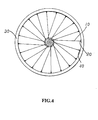
- the wheel rim as shown in Fig. 4 has a better swing allowance and better conductive and waterproof functions.
- the inner layer 43 of the ferrule 40 has a flared surface 431 for swing of the spoke connector 20 to assemble a complete wheel rim as shown in Fig. 4 .
- the ferrule 40 fitted on the spoke connector 20 and the wheel rim 30 form a semi-finished product.
- the inner flange 44A at the upper end of the inner layer 43 of the ferrule 40 or the upper end of the flared surface 431 laps over an upper surface of the outer flange 42.
- the inner flange 44B is adjacent to the outer flange 42.
- the inner flange 44B and the outer flange 42 have an equal height.
- the inner flange 44C at the upper end of the inner layer 43 of the ferrule 40 or the upper end of the flared surface 431 covers the outer flange 42 at the upper end of the outer layer 41.
- the ferrule 40 has reinforcement protrusions 432 which are disposed on the inner layer 43 between the cut lines 45 of the engaging section 46 corresponding to the straight section 22 of the spoke connector 20 to reduce the thickness of the ferrule 40 so as to save the material and lighten the ferrule 40.
- the reinforcement protrusions 432 are in contact with the head 23 of the spoke connector 20 to prevent the head 23 from being scraped.
- annular reinforcement member 24 is provided between the head 23 of the spoke connector 20 and the engaging section 46 of the ferrule 40.
- the ferrule 40 has a clamping portion 434 disposed at the upper end of the inner layer 43 of the ferrule 40 (or the upper end of the flared surface 431 as shown in Fig. 11 ) and the inner flange 44C to cover the outer flange 42 and to be positioned at the periphery of the hole 31 of the wheel rim 30.
Landscapes
- Engineering & Computer Science (AREA)
- Mechanical Engineering (AREA)
- Length Measuring Devices By Optical Means (AREA)
- Connector Housings Or Holding Contact Members (AREA)
- Earth Drilling (AREA)
Claims (12)
- Ein Aufbau einer Positionierzwinge für eine Speiche einer Radfelge besteht aus einer Zwinge (40), dadurch gekennzeichnet, dass eine Zwinge (40) als eine hohle und doppelschichtige Zwinge gebildet ist und aus einer Innenschicht (43) und einer Außenschicht (41) besteht, die durch Stanzen integral miteinander geformt sind, wobei die Außenschicht (41) einen Außenflansch (42) aufweist, der größer ist als ein Loch (31) einer Radfelge (30) und an einem oberen Ende der Außenschicht (41) gebildet ist; die Innenschicht (43) ist mit einem Innenflansch (44) versehen, der an einem oberen Ende der Innenschicht (43) geformt ist und den Außenflansch (42) überlappt; die unteren Teile der Innenschicht (43) und der Außenschicht (41) integral miteinander gebildet sind und mehrere Längsschnittlinien (45) aufweisen, um ein doppelschichtiges Einrückteil (46) zu bilden.
- Der Aufbau der Positionierzwinge nach Anspruch 1, dadurch gekennzeichnet, dass der Innenflansch (44) kleiner ist als der Außenflansch (42) und diesen Außenflansch (42) überlappt, um eine abgestufte Konfiguration zu bilden.
- Der Aufbau der Positionierzwinge nach Anspruch 1, dadurch gekennzeichnet, dass der Innenflansch (44A) an einer oberen Oberfläche des Außenflansches (42) befestigt ist.
- Der Aufbau der Positionierzwinge nach Anspruch 1, dadurch gekennzeichnet, dass der Innenflansch (44B) neben dem Außenflansch (42) gebildet ist, wobei sowohl der Innenflansch (44B) als auch der Außenflansch (42) dieselbe Höhe aufweisen.
- Der Aufbau der Positionierzwinge nach Anspruch 1, dadurch gekennzeichnet, dass der Außenflansch (42) mit dem Innenflansch (44C) abgedeckt wird.
- Der Aufbau der Positionierzwinge nach Anspruch 1, dadurch gekennzeichnet, dass am oberen Ende der Innenschicht (43) ein Klemmelement (434) und der Innenflansch (44C) gebildet sind, mit dem der Außenflansch (42) abgedeckt wird.
- Der Aufbau der Positionierzwinge nach Anspruch 1, 2, 3, 4, 5 oder 6, dadurch gekennzeichnet, dass die Zwinge (40) mit verstärkenden Vorsprüngen (432) versehen ist, die auf der Innenschicht (43) zwischen den Schnittlinien (45) des Einrückteils (46) gebildet sind.
- Der Aufbau der Positionierzwinge nach Anspruch 1, 2, 3, 4, 5 oder 6, dadurch gekennzeichnet, dass zwischen dem Kopfteil (23) der Speichenbefestigung (20) und dem Einrückteil (46) ein ringförmiges Verstärkungsglied (24) montiert ist.
- Der Aufbau der Positionierzwinge nach Anspruch 7, dadurch gekennzeichnet, dass zwischen dem Kopfteil (23) der Speichenbefestigung (20) und dem doppelschichtigen Einrückteil (46) ein ringförmiges Verstärkungsglied (24) montiert ist.
- Der Aufbau der Positionierzwinge nach Anspruch 1, 2, 3, 4, 5 oder 6, dadurch gekennzeichnet, dass an einem oberen Teil der Innenschicht (43) eine ausladende Oberfläche (431) gebildet ist.
- Der Aufbau der Positionierzwinge nach Anspruch 7 oder 9, dadurch gekennzeichnet, dass an einem oberen Teil der Innenschicht (43) eine ausladende Oberfläche (431) gebildet ist.
- Der Aufbau der Positionierzwinge nach Anspruch 8, dadurch gekennzeichnet, dass an einem oberen Teil der Innenschicht (43) eine ausladende Oberfläche (431) gebildet ist.
Applications Claiming Priority (1)
| Application Number | Priority Date | Filing Date | Title |
|---|---|---|---|
| TW099109082A TW201132517A (en) | 2010-03-26 | 2010-03-26 | Wheel rim spoke ferrule fastening member |
Publications (2)
| Publication Number | Publication Date |
|---|---|
| EP2371577A1 EP2371577A1 (de) | 2011-10-05 |
| EP2371577B1 true EP2371577B1 (de) | 2012-12-05 |
Family
ID=44168226
Family Applications (1)
| Application Number | Title | Priority Date | Filing Date |
|---|---|---|---|
| EP11159362A Active EP2371577B1 (de) | 2010-03-26 | 2011-03-23 | Positionierungshülsenstruktur für Speichen einer Radfelge |
Country Status (3)
| Country | Link |
|---|---|
| EP (1) | EP2371577B1 (de) |
| ES (1) | ES2400444T3 (de) |
| TW (1) | TW201132517A (de) |
Families Citing this family (2)
| Publication number | Priority date | Publication date | Assignee | Title |
|---|---|---|---|---|
| TW201328901A (zh) * | 2012-01-04 | 2013-07-16 | Kunshan Henry Metal Tech Co | 輪圈及其輻條組結構 |
| CN104417251A (zh) * | 2013-08-23 | 2015-03-18 | 许栋樑 | 轮辐可转向的可收叠轮子 |
Family Cites Families (7)
| Publication number | Priority date | Publication date | Assignee | Title |
|---|---|---|---|---|
| US6938962B1 (en) * | 2002-03-18 | 2005-09-06 | Raphael Schlanger | Vehicle wheel spoke termination |
| FR2862568B3 (fr) * | 2003-11-26 | 2005-10-07 | Wen Pin Liu | Structure de montage de roue de bicyclette |
| TWM252567U (en) * | 2004-03-03 | 2004-12-11 | Jen-Ping Tian | Improved assembly structure for wheel rim spokes of bicycle |
| TWI280926B (en) * | 2005-04-11 | 2007-05-11 | Yu-Ru Wang | Combination structure of felly spoke without inner tube |
| DE102006035814A1 (de) * | 2006-08-01 | 2008-02-07 | Tien, Tseng-Ping, Hou Li Hsiang | Konstruktion einer Sicherungsbuchse einer Felgenspeiche |
| US20080290721A1 (en) * | 2007-05-22 | 2008-11-27 | Yuhju Wang | Spoke fastening device for vehicle wheel |
| TWM329119U (en) * | 2007-07-27 | 2008-03-21 | Tai Yen Prec Industry Co Ltd | Nut with double thickness |
-
2010
- 2010-03-26 TW TW099109082A patent/TW201132517A/zh unknown
-
2011
- 2011-03-23 EP EP11159362A patent/EP2371577B1/de active Active
- 2011-03-23 ES ES11159362T patent/ES2400444T3/es active Active
Also Published As
| Publication number | Publication date |
|---|---|
| TW201132517A (en) | 2011-10-01 |
| ES2400444T3 (es) | 2013-04-09 |
| EP2371577A1 (de) | 2011-10-05 |
| TWI401168B (de) | 2013-07-11 |
Similar Documents
| Publication | Publication Date | Title |
|---|---|---|
| US9085338B2 (en) | Bicycle expander | |
| JPWO2012147645A1 (ja) | キャップおよびこれを用いた固定構造部 | |
| EP2612765A2 (de) | Felgenanordnung | |
| EP2905146A2 (de) | Verbindungsstruktur zwischen luftlosem Reifen und Felge und Befestigungselemente dafür | |
| WO2007046940A3 (en) | Air filter with composite plastic and urethane end cap | |
| EP2371577B1 (de) | Positionierungshülsenstruktur für Speichen einer Radfelge | |
| US6776460B1 (en) | Combination of spokes and rims for bicycles | |
| US20140132060A1 (en) | Bicycle Wheel Rim | |
| US20110061491A1 (en) | Bearing device for bicycle pedal | |
| KR101465055B1 (ko) | 타이어 휠 보호캡 | |
| US20100326231A1 (en) | Protection sheath for bicycle operation cables | |
| EP2500182B1 (de) | Sicherungsvorrichtung für Speichen | |
| US20060027298A1 (en) | Enhanced hollow foam tire structure | |
| USD677198S1 (en) | Suspension module with snap ring | |
| US20110219910A1 (en) | Grip Sleeve Assembly | |
| US20140145497A1 (en) | Connectible wheel rim structure for a bicycle | |
| EP2325074B1 (de) | Verschlussanordnung für einen gewindelosen Fahrradsteuersatz | |
| WO2010080394A3 (en) | Sealing grommet for fluid filters | |
| US9469367B2 (en) | Handlebar end caps for bicycle | |
| JP3161327U (ja) | 双パッキン式電源ケーブル及び波管防水固定ヘッド | |
| US5476327A (en) | Bottom bracket for a bicycle | |
| US9254710B2 (en) | Supporting device for a bicycle wheel | |
| US20060210734A1 (en) | Composite material tube with inlaid element | |
| JP2014115470A5 (de) | ||
| JP5260372B2 (ja) | 道路用標示体および押圧装置 |
Legal Events
| Date | Code | Title | Description |
|---|---|---|---|
| PUAI | Public reference made under article 153(3) epc to a published international application that has entered the european phase |
Free format text: ORIGINAL CODE: 0009012 |
|
| AK | Designated contracting states |
Kind code of ref document: A1 Designated state(s): AL AT BE BG CH CY CZ DE DK EE ES FI FR GB GR HR HU IE IS IT LI LT LU LV MC MK MT NL NO PL PT RO RS SE SI SK SM TR |
|
| AX | Request for extension of the european patent |
Extension state: BA ME |
|
| 17P | Request for examination filed |
Effective date: 20111026 |
|
| GRAP | Despatch of communication of intention to grant a patent |
Free format text: ORIGINAL CODE: EPIDOSNIGR1 |
|
| RIC1 | Information provided on ipc code assigned before grant |
Ipc: B60B 1/04 20060101AFI20120529BHEP Ipc: B60B 21/06 20060101ALI20120529BHEP |
|
| GRAS | Grant fee paid |
Free format text: ORIGINAL CODE: EPIDOSNIGR3 |
|
| GRAA | (expected) grant |
Free format text: ORIGINAL CODE: 0009210 |
|
| RAP1 | Party data changed (applicant data changed or rights of an application transferred) |
Owner name: WANG, YU JU |
|
| RIN1 | Information on inventor provided before grant (corrected) |
Inventor name: WANG, YU JU |
|
| AK | Designated contracting states |
Kind code of ref document: B1 Designated state(s): AL AT BE BG CH CY CZ DE DK EE ES FI FR GB GR HR HU IE IS IT LI LT LU LV MC MK MT NL NO PL PT RO RS SE SI SK SM TR |
|
| REG | Reference to a national code |
Ref country code: GB Ref legal event code: FG4D |
|
| REG | Reference to a national code |
Ref country code: CH Ref legal event code: EP |
|
| REG | Reference to a national code |
Ref country code: AT Ref legal event code: REF Ref document number: 587058 Country of ref document: AT Kind code of ref document: T Effective date: 20121215 |
|
| REG | Reference to a national code |
Ref country code: IE Ref legal event code: FG4D |
|
| REG | Reference to a national code |
Ref country code: DE Ref legal event code: R096 Ref document number: 602011000537 Country of ref document: DE Effective date: 20130131 |
|
| REG | Reference to a national code |
Ref country code: NL Ref legal event code: T3 |
|
| REG | Reference to a national code |
Ref country code: ES Ref legal event code: FG2A Ref document number: 2400444 Country of ref document: ES Kind code of ref document: T3 Effective date: 20130409 |
|
| REG | Reference to a national code |
Ref country code: AT Ref legal event code: MK05 Ref document number: 587058 Country of ref document: AT Kind code of ref document: T Effective date: 20121205 |
|
| PG25 | Lapsed in a contracting state [announced via postgrant information from national office to epo] |
Ref country code: LT Free format text: LAPSE BECAUSE OF FAILURE TO SUBMIT A TRANSLATION OF THE DESCRIPTION OR TO PAY THE FEE WITHIN THE PRESCRIBED TIME-LIMIT Effective date: 20121205 Ref country code: NO Free format text: LAPSE BECAUSE OF FAILURE TO SUBMIT A TRANSLATION OF THE DESCRIPTION OR TO PAY THE FEE WITHIN THE PRESCRIBED TIME-LIMIT Effective date: 20130305 Ref country code: SE Free format text: LAPSE BECAUSE OF FAILURE TO SUBMIT A TRANSLATION OF THE DESCRIPTION OR TO PAY THE FEE WITHIN THE PRESCRIBED TIME-LIMIT Effective date: 20121205 Ref country code: FI Free format text: LAPSE BECAUSE OF FAILURE TO SUBMIT A TRANSLATION OF THE DESCRIPTION OR TO PAY THE FEE WITHIN THE PRESCRIBED TIME-LIMIT Effective date: 20121205 |
|
| REG | Reference to a national code |
Ref country code: LT Ref legal event code: MG4D |
|
| PG25 | Lapsed in a contracting state [announced via postgrant information from national office to epo] |
Ref country code: GR Free format text: LAPSE BECAUSE OF FAILURE TO SUBMIT A TRANSLATION OF THE DESCRIPTION OR TO PAY THE FEE WITHIN THE PRESCRIBED TIME-LIMIT Effective date: 20130306 Ref country code: SI Free format text: LAPSE BECAUSE OF FAILURE TO SUBMIT A TRANSLATION OF THE DESCRIPTION OR TO PAY THE FEE WITHIN THE PRESCRIBED TIME-LIMIT Effective date: 20121205 Ref country code: PL Free format text: LAPSE BECAUSE OF FAILURE TO SUBMIT A TRANSLATION OF THE DESCRIPTION OR TO PAY THE FEE WITHIN THE PRESCRIBED TIME-LIMIT Effective date: 20121205 Ref country code: LV Free format text: LAPSE BECAUSE OF FAILURE TO SUBMIT A TRANSLATION OF THE DESCRIPTION OR TO PAY THE FEE WITHIN THE PRESCRIBED TIME-LIMIT Effective date: 20121205 |
|
| PG25 | Lapsed in a contracting state [announced via postgrant information from national office to epo] |
Ref country code: AT Free format text: LAPSE BECAUSE OF FAILURE TO SUBMIT A TRANSLATION OF THE DESCRIPTION OR TO PAY THE FEE WITHIN THE PRESCRIBED TIME-LIMIT Effective date: 20121205 |
|
| PG25 | Lapsed in a contracting state [announced via postgrant information from national office to epo] |
Ref country code: SK Free format text: LAPSE BECAUSE OF FAILURE TO SUBMIT A TRANSLATION OF THE DESCRIPTION OR TO PAY THE FEE WITHIN THE PRESCRIBED TIME-LIMIT Effective date: 20121205 Ref country code: BG Free format text: LAPSE BECAUSE OF FAILURE TO SUBMIT A TRANSLATION OF THE DESCRIPTION OR TO PAY THE FEE WITHIN THE PRESCRIBED TIME-LIMIT Effective date: 20130305 Ref country code: IS Free format text: LAPSE BECAUSE OF FAILURE TO SUBMIT A TRANSLATION OF THE DESCRIPTION OR TO PAY THE FEE WITHIN THE PRESCRIBED TIME-LIMIT Effective date: 20130405 Ref country code: BE Free format text: LAPSE BECAUSE OF FAILURE TO SUBMIT A TRANSLATION OF THE DESCRIPTION OR TO PAY THE FEE WITHIN THE PRESCRIBED TIME-LIMIT Effective date: 20121205 Ref country code: CZ Free format text: LAPSE BECAUSE OF FAILURE TO SUBMIT A TRANSLATION OF THE DESCRIPTION OR TO PAY THE FEE WITHIN THE PRESCRIBED TIME-LIMIT Effective date: 20121205 Ref country code: EE Free format text: LAPSE BECAUSE OF FAILURE TO SUBMIT A TRANSLATION OF THE DESCRIPTION OR TO PAY THE FEE WITHIN THE PRESCRIBED TIME-LIMIT Effective date: 20121205 Ref country code: RS Free format text: LAPSE BECAUSE OF FAILURE TO SUBMIT A TRANSLATION OF THE DESCRIPTION OR TO PAY THE FEE WITHIN THE PRESCRIBED TIME-LIMIT Effective date: 20121205 |
|
| PG25 | Lapsed in a contracting state [announced via postgrant information from national office to epo] |
Ref country code: RO Free format text: LAPSE BECAUSE OF FAILURE TO SUBMIT A TRANSLATION OF THE DESCRIPTION OR TO PAY THE FEE WITHIN THE PRESCRIBED TIME-LIMIT Effective date: 20121205 Ref country code: PT Free format text: LAPSE BECAUSE OF FAILURE TO SUBMIT A TRANSLATION OF THE DESCRIPTION OR TO PAY THE FEE WITHIN THE PRESCRIBED TIME-LIMIT Effective date: 20130405 |
|
| PLBE | No opposition filed within time limit |
Free format text: ORIGINAL CODE: 0009261 |
|
| STAA | Information on the status of an ep patent application or granted ep patent |
Free format text: STATUS: NO OPPOSITION FILED WITHIN TIME LIMIT |
|
| PG25 | Lapsed in a contracting state [announced via postgrant information from national office to epo] |
Ref country code: MC Free format text: LAPSE BECAUSE OF NON-PAYMENT OF DUE FEES Effective date: 20130331 Ref country code: DK Free format text: LAPSE BECAUSE OF FAILURE TO SUBMIT A TRANSLATION OF THE DESCRIPTION OR TO PAY THE FEE WITHIN THE PRESCRIBED TIME-LIMIT Effective date: 20121205 |
|
| 26N | No opposition filed |
Effective date: 20130906 |
|
| PG25 | Lapsed in a contracting state [announced via postgrant information from national office to epo] |
Ref country code: CY Free format text: LAPSE BECAUSE OF FAILURE TO SUBMIT A TRANSLATION OF THE DESCRIPTION OR TO PAY THE FEE WITHIN THE PRESCRIBED TIME-LIMIT Effective date: 20121205 |
|
| REG | Reference to a national code |
Ref country code: IE Ref legal event code: MM4A |
|
| REG | Reference to a national code |
Ref country code: DE Ref legal event code: R097 Ref document number: 602011000537 Country of ref document: DE Effective date: 20130906 |
|
| PG25 | Lapsed in a contracting state [announced via postgrant information from national office to epo] |
Ref country code: IE Free format text: LAPSE BECAUSE OF NON-PAYMENT OF DUE FEES Effective date: 20130323 Ref country code: AL Free format text: LAPSE BECAUSE OF FAILURE TO SUBMIT A TRANSLATION OF THE DESCRIPTION OR TO PAY THE FEE WITHIN THE PRESCRIBED TIME-LIMIT Effective date: 20121205 Ref country code: HR Free format text: LAPSE BECAUSE OF FAILURE TO SUBMIT A TRANSLATION OF THE DESCRIPTION OR TO PAY THE FEE WITHIN THE PRESCRIBED TIME-LIMIT Effective date: 20130731 |
|
| PG25 | Lapsed in a contracting state [announced via postgrant information from national office to epo] |
Ref country code: MT Free format text: LAPSE BECAUSE OF FAILURE TO SUBMIT A TRANSLATION OF THE DESCRIPTION OR TO PAY THE FEE WITHIN THE PRESCRIBED TIME-LIMIT Effective date: 20121205 |
|
| REG | Reference to a national code |
Ref country code: CH Ref legal event code: PL |
|
| PG25 | Lapsed in a contracting state [announced via postgrant information from national office to epo] |
Ref country code: LI Free format text: LAPSE BECAUSE OF NON-PAYMENT OF DUE FEES Effective date: 20140331 Ref country code: CH Free format text: LAPSE BECAUSE OF NON-PAYMENT OF DUE FEES Effective date: 20140331 |
|
| PG25 | Lapsed in a contracting state [announced via postgrant information from national office to epo] |
Ref country code: SM Free format text: LAPSE BECAUSE OF FAILURE TO SUBMIT A TRANSLATION OF THE DESCRIPTION OR TO PAY THE FEE WITHIN THE PRESCRIBED TIME-LIMIT Effective date: 20121205 |
|
| PG25 | Lapsed in a contracting state [announced via postgrant information from national office to epo] |
Ref country code: TR Free format text: LAPSE BECAUSE OF FAILURE TO SUBMIT A TRANSLATION OF THE DESCRIPTION OR TO PAY THE FEE WITHIN THE PRESCRIBED TIME-LIMIT Effective date: 20121205 |
|
| PG25 | Lapsed in a contracting state [announced via postgrant information from national office to epo] |
Ref country code: LU Free format text: LAPSE BECAUSE OF NON-PAYMENT OF DUE FEES Effective date: 20130323 Ref country code: HU Free format text: LAPSE BECAUSE OF FAILURE TO SUBMIT A TRANSLATION OF THE DESCRIPTION OR TO PAY THE FEE WITHIN THE PRESCRIBED TIME-LIMIT; INVALID AB INITIO Effective date: 20110323 Ref country code: MK Free format text: LAPSE BECAUSE OF FAILURE TO SUBMIT A TRANSLATION OF THE DESCRIPTION OR TO PAY THE FEE WITHIN THE PRESCRIBED TIME-LIMIT Effective date: 20121205 |
|
| PG25 | Lapsed in a contracting state [announced via postgrant information from national office to epo] |
Ref country code: IT Free format text: LAPSE BECAUSE OF NON-PAYMENT OF DUE FEES Effective date: 20150323 |
|
| REG | Reference to a national code |
Ref country code: FR Ref legal event code: PLFP Year of fee payment: 6 |
|
| REG | Reference to a national code |
Ref country code: FR Ref legal event code: PLFP Year of fee payment: 7 |
|
| PG25 | Lapsed in a contracting state [announced via postgrant information from national office to epo] |
Ref country code: IT Free format text: LAPSE BECAUSE OF NON-PAYMENT OF DUE FEES Effective date: 20150323 |
|
| PGRI | Patent reinstated in contracting state [announced from national office to epo] |
Ref country code: IT Effective date: 20180104 |
|
| REG | Reference to a national code |
Ref country code: FR Ref legal event code: PLFP Year of fee payment: 8 |
|
| PGFP | Annual fee paid to national office [announced via postgrant information from national office to epo] |
Ref country code: NL Payment date: 20180326 Year of fee payment: 8 |
|
| PGFP | Annual fee paid to national office [announced via postgrant information from national office to epo] |
Ref country code: ES Payment date: 20180402 Year of fee payment: 8 |
|
| PGFP | Annual fee paid to national office [announced via postgrant information from national office to epo] |
Ref country code: IT Payment date: 20180328 Year of fee payment: 8 |
|
| REG | Reference to a national code |
Ref country code: NL Ref legal event code: MM Effective date: 20190401 |
|
| PG25 | Lapsed in a contracting state [announced via postgrant information from national office to epo] |
Ref country code: NL Free format text: LAPSE BECAUSE OF NON-PAYMENT OF DUE FEES Effective date: 20190401 |
|
| PG25 | Lapsed in a contracting state [announced via postgrant information from national office to epo] |
Ref country code: IT Free format text: LAPSE BECAUSE OF NON-PAYMENT OF DUE FEES Effective date: 20190323 |
|
| REG | Reference to a national code |
Ref country code: ES Ref legal event code: FD2A Effective date: 20200727 |
|
| PG25 | Lapsed in a contracting state [announced via postgrant information from national office to epo] |
Ref country code: ES Free format text: LAPSE BECAUSE OF NON-PAYMENT OF DUE FEES Effective date: 20190324 |
|
| PGFP | Annual fee paid to national office [announced via postgrant information from national office to epo] |
Ref country code: DE Payment date: 20250327 Year of fee payment: 15 |
|
| PGFP | Annual fee paid to national office [announced via postgrant information from national office to epo] |
Ref country code: FR Payment date: 20250325 Year of fee payment: 15 |
|
| PGFP | Annual fee paid to national office [announced via postgrant information from national office to epo] |
Ref country code: GB Payment date: 20250210 Year of fee payment: 15 |