EP2371307B1 - Verarbeitungsgerät mit einem mobilen Druckwellengenerator - Google Patents
Verarbeitungsgerät mit einem mobilen Druckwellengenerator Download PDFInfo
- Publication number
- EP2371307B1 EP2371307B1 EP20110158753 EP11158753A EP2371307B1 EP 2371307 B1 EP2371307 B1 EP 2371307B1 EP 20110158753 EP20110158753 EP 20110158753 EP 11158753 A EP11158753 A EP 11158753A EP 2371307 B1 EP2371307 B1 EP 2371307B1
- Authority
- EP
- European Patent Office
- Prior art keywords
- generator
- arm
- treatment
- housing
- opening
- Prior art date
- Legal status (The legal status is an assumption and is not a legal conclusion. Google has not performed a legal analysis and makes no representation as to the accuracy of the status listed.)
- Active
Links
Images


Classifications
-
- A—HUMAN NECESSITIES
- A61—MEDICAL OR VETERINARY SCIENCE; HYGIENE
- A61B—DIAGNOSIS; SURGERY; IDENTIFICATION
- A61B17/00—Surgical instruments, devices or methods
- A61B17/22—Implements for squeezing-off ulcers or the like on inner organs of the body; Implements for scraping-out cavities of body organs, e.g. bones; for invasive removal or destruction of calculus using mechanical vibrations; for removing obstructions in blood vessels, not otherwise provided for
- A61B17/225—Implements for squeezing-off ulcers or the like on inner organs of the body; Implements for scraping-out cavities of body organs, e.g. bones; for invasive removal or destruction of calculus using mechanical vibrations; for removing obstructions in blood vessels, not otherwise provided for for extracorporeal shock wave lithotripsy [ESWL], e.g. by using ultrasonic waves
- A61B17/2255—Means for positioning patient, shock wave apparatus or locating means, e.g. mechanical aspects, patient beds, support arms or aiming means
Definitions
- the present invention relates to an apparatus for destroying solid intracorporeal concretions for lithotripsy treatments.
- a lithotripsy apparatus comprises a pressure wave generator such as acoustic shock waves for destroying concretions or renal, biliary or salivary lithiases.
- a lithotripsy apparatus is associated with an X-ray or ultrasound imaging device for detecting and visualizing the presence of lithiases in the body of a patient or an animal.
- the lithiases and the focus of the generator are put into coincidence using mechanical displacement systems to bring either the lithiases on the focus point of the generator, or the point of focus of the generator on the lithiases.
- a lithotripsy apparatus is associated with a treatment table which advantageously comprises a cut-out for housing the generator so that the generator can be, in order to be effective, in contact with the patient while allowing the patient to lie on the table without overflowing the table.
- Such lithotripsy equipment namely a treatment device associated with its imaging device and a treatment table is widely used in hospitals. On various occasions, it appears the need to use some of this equipment to provide treatments other than lithotripsy treatments such as for example acts of endourology. These acts consist, for example, in introducing urinary tract probes under the guidance of "X" rays to reach the bladder or the kidneys in order to perform medical procedures.
- lithotripsy device In the same way, during endourology procedures, some medical teams prefer to separate the lithotripsy device from the patient's support table and move it away from this table to place it outside the treatment room. Such a lithotripsy device is then exposed to risks of mishandling and clashes by other medical equipment likely to affect its integrity.
- a pressure wave treatment apparatus comprising a pressure wave generator mounted via a guide structure, on a frame inside which is arranged a housing opening out of the frame by a opening arranged on the top of the chassis.
- the guiding structure allows the generator to move relative to the frame, between a retracted position in which the generator is located inside the housing and a treatment position in which the generator is out of the housing through the opening.
- the carrier frame of the pressure wave generator is slidably mounted on a mobile carriage on the frame of the treatment apparatus.
- the combined movements of the carriage, the frame and the guide structure enable the pressure wave generator to be positioned in its treatment position.
- the kinematics of this pressure wave generator appear relatively bulky and complex to implement.
- the pressure wave generator is able to occupy a retracted position inside the frame, it should be noted that this pressure wave generator is not protected against attacks likely to occur. intervene through the opening of passage arranged on the top of the chassis.
- the present invention therefore aims to remedy the drawbacks of the state of the art by proposing a new wave-wave treatment apparatus.
- pressure designed to allow the pressure wave generator to be easily positioned in its treatment position and a retracted position easily removed from the treatment table while ensuring its total protection against including shocks or shocks in position retracted.
- Another object of the invention is to provide a treatment apparatus of small size maintaining ease of implementation and having a reduced cost.
- the object of the invention is a pressure wave treatment apparatus comprising a pressure wave generator, mounted via a guide structure on a frame inside. which is arranged a housing opening outside the frame through an opening of the generator, the guide structure being mounted on the frame to register in the housing and allow the displacement of the generator relative to the frame, between a withdrawal position wherein the generator is located inside the housing and a processing position in which the generator is out of the housing through the opening.
- the generator is mounted at the end of an arm supported by the guide structure and the housing contains, in the retracted position, the arm and the generator completely, a display screen being mounted in a cover supported by a displacement structure adapted to place the lid in a closed position of the opening, and in a position outside the opening to allow the output of the generator
- the object of the invention relates to a treatment apparatus 1 by pressure waves, intracorporeal concretions localized in the body of a patient or an animal, with the aid of an imaging system not described but known in itself.
- the treatment apparatus 1 according to the invention such as a lithotripsy apparatus, comprises a frame or a frame 2 equipped with a generator 3 of pressure waves such as acoustic shock waves.
- the frame 2 has a substantially parallelepipedal shape and is advantageously wrapped by a cowling or protective walls.
- the frame 2 is thus equipped with two side walls 2 1 extending substantially parallel to each other and interconnected on one side by a rear wall 2 2 and on the other side by a front wall 2 3 .
- the side walls 2 1 and the front walls 2 3 and 2 2 rear are joined together at their upper parts, by a top wall 2 4 .
- the chassis 2 is equipped with wheels 4 for rolling and moving the chassis 2 .
- the generator 3 is adapted to emit acoustic shock waves directed towards a target focus that is sought to coincide via an imaging system, with the concretions with a view to destroying these latest.
- the generator 3 comprises an ellipsoidal reflector 5 in which is positioned an electrode which makes it possible to generate an acoustic shock wave at the first focus of the ellipsoidal reflector 5 .
- the shock wave produced at the first focus is reflected at the second focus of the reflector, the second focus being outside the generator, which allows to target concretions located in the body of the reflector. a patient or an animal.
- the generator 3 is not described more precisely because it is not a part of the invention and its realization is well known to those skilled in the art.
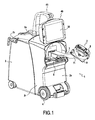
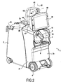
- the generator 3 is mounted at the distal end 7 1 of an arm 7 mounted on the frame 2 by means of a guide structure 8 enabling the generator 3 to move between a treatment position illustrated in FIG. Fig. 1 in which the generator 3 is in the furthest position from the frame 2 and a withdrawal position illustrated in FIG. Fig. 2 in which the generator 3 is retracted inside the frame 2.
- the generator 3 is mounted at the distal end 7 1 of the arm 7, via a pivot connection 9 , allowing the generator 3 to be oriented relative to on the arm 7 .
- the frame 2 is arranged to delimit internally, a housing 11 opening out of the frame 2 through an opening 12.
- the opening 12 is arranged in the front wall 2 3 of the frame extending in a substantially vertical plane.
- the opening 12 is arranged to allow the outlet of the arm 7 and the generator 3 so that the latter reaches its treatment position ( Fig. 1 ) in which the generator 3 is located outside the frame 2.
- the housing 11 is arranged for in the retracted position, completely contain the arm 7 and the generator 3 ( Fig.2 ).
- the guide structure 8 fits into the housing 11, that is to say, it is mounted inside the housing 11 to allow movement of the arm 7 and the generator 3 between its withdrawal position and its treatment position.
- the generator 3 is completely located inside the frame 2 so as to be protected against any shock or shock.
- the frame 2 is provided with protective walls 2 1 , 2 2 , 2 3 , 2 4 completely protecting the apparatus 1 but it is clear that the frame 2 may be partially or completely free of protective walls while performing its function of protecting the generator 3 .
- the housing 11 is formed inside a more or less open frame being delimited by uprights and / or sleepers.
- the path of the generator 3 inside the chassis 2 is optimized to limit the size of the housing 11 and therefore the size of the device 1 .
- the guide structure 8 comprises means for guiding the generator 3 along a linear trajectory inside the housing 11 and until it is positioned at the opening 12 .
- the guide structure 8 comprises means for guiding the generator 3 along a curved path between the opening 12 and the treatment position illustrated in FIG. Fig. 1 . This curved trajectory is advantageously designed to allow the establishment and removal of the generator 3 inside the cutout arranged in the treatment table while avoiding the imaging system.
- the guide structure 8 comprises a carriage 14 adapted to support the arm 7 .
- the carriage 14 is mounted linearly relative to the frame 2.
- the carriage 14 is moved manually but it is clear that its displacement can be motorized.
- the carriage 14 is mounted linearly on a set of rails 15 fixed to a plate 25 forming part of the frame 2 . These straight slides 15 allow the carriage 14 to have a linear path inside the housing 11 .
- the arm 7 is mounted on the carriage 14 in a pivot connection 16 .
- the pivot connection 16 is arranged at a distal end 7 2 of the arm 7 extending opposite the distal end 7 1 equipped with the generator 3 .
- the pivot connection 16 is made by any appropriate means for obtaining a rotation of the arm 7 relative to the carriage 14 and around a vertical axis X.
- the arm 7 has a bent shape.
- the arm 7 comprises from its proximal end 7 2 , a first straight segment 7 3 extended substantially to the square by a second straight segment 7 4 at the end of which is fixed the generator 3 .
- the guiding structure 8 also comprises a cam system 18 and follower element 19 interposed between the arm 7 and the chassis 2 making it possible to define the trajectory of the arm 7.
- the cam 18 is mounted on the chassis 2 (More precisely on the plate 2 5 ) while the follower member 19 is mounted integral with the arm 7.
- the cam 18 is formed via the profile of a groove 20 .
- the cam 18 is removably mounted on the frame 2 by screws 21 allowing its change by another cam having a groove of different profile thus conferring a different trajectory to the arm 7 .
- the follower element 19 is in the form of a finger engaged inside the groove 20 of the cam.
- the follower element 19 follows the profile of the cam 18 when the carriage 14 is moved linearly along the slides 15.
- the kinematics of the arm 7 corresponds to the profile of the cam 18 made possible by the combination of the linear movement of the carriage and the movement of rotation of the arm 7 around the pivot connection 16.
- the cam 18 has a first segment 20 1 substantially parallel to the slide 15 and corresponding to the linear path of the generator 3 inside the housing.
- the first segment 20 1 whose end defines the withdrawal position ( Fig. 4C ) is extended by a second rectilinear segment 2 making a first angulation relative to the first segment 1 .
- the second segment 2 is extended by a third segment 3 which extends in a direction substantially perpendicular to the first segment 1 .
- the end of the third segment 3 defines the treatment position illustrated in FIG. Fig. 4A for the generator 3 .
- the cam 18 may have a different profile depending on the desired path for the generator 3 .
- the relative position between the cam 18 and the pivot connection 16 is chosen so that in the retracted position ( Fig. 4C ), the arm 7 has a limited size.
- the cam 18 and the pivot connection 16 are mounted relative to each other so that when the carriage 14 moves along the first straight segment 20 1 of the slides 15, the arm 7 extends substantially symmetrically with respect to the linear direction moving the carriage 14.
- the guiding structure 8 comprises a device 25 for locking the arm 7 in selected or predetermined positions along its trajectory defined by the cam 18 .
- the fixed positions of the arm 7 correspond to the treatment position ( Fig. 4A ), at the withdrawal position ( Fig. 4C ) and at an intermediate position ( Fig. 4B ) between the retracted position and the treatment position.
- This intermediate position corresponds, for example, to a limited recoil of the generator 3 relative to the generator in the treatment position, for example making it easier to access the patient, for example to place the acoustic coupling gel of the pressure waves on the patient.
- the processing apparatus 1 comprises a device for locking the arm 7 when the latter occupies its retracted position.
- This mechanical type locking device ensures the attachment of the arm 7 relative to the frame in particular during the transport operations of the device.
- this locking device comprises a threaded rod extending from the carriage 14 to pass through a plate of the frame 2 and on which is screwed a clamping nut.
- the processing apparatus 1 comprises a position sensor adapted to detect when the arm 7 occupies the treatment position.
- this position sensor detects the presence of the follower element 19 when it is at the hole 31a.
- the processing apparatus 1 includes a display screen 35 of the LCD type, for example for visualization and / or command in connection with the operation of the apparatus 1.
- This screen 35 is mounted in a cover 40 which is supported by a displacement structure 41 .
- the displacement structure 41 is able to place the lid 40 in a closed position ( Fig. 6 ) or opening ( Fig. 2 ) of the housing 11.
- the cover 40 has a section at least equal to or even slightly greater than the section of the opening 12 of the housing to allow its perfect closure or closure and the protection of the generator 3 placed inside the housing 11 .
- the apparatus comprises a not shown system for locking the cover 40 on the frame 2 , in the closed position of the opening 12 .
- the cover 40 is fixed for example by means of hooks on the chassis avoiding any inadvertent movement likely to damage the screen 35 during the transport of the device 1 .
- the apparatus 1 has a limited size and a compact form ( Fig. 6 ).
- This displacement structure 41 comprises, as is more specifically apparent from Fig. 2 and 6 at least one support arm 42 at the end of which the cover 40 is mounted , on the one hand, with a vertical axis of rotation 43 for pivoting the cover 40 on itself, along an axis vertical of so as to place the screen 35 facing the frame, or in the opposite direction of the frame and secondly, at least one horizontal axis of rotation 44 for lifting and / or lowering the lid relative to the frame. opening 12 .
- the support arm 42 is connected to the frame 2 by means of a hinge 46 allowing rotation of the support arm 42 on itself along a vertical axis 47 and the lowering or raising of the support arm 42 according to a horizontal axis 48 .
- the rotation of the support arm 42 along the horizontal axis 48 contributes to the closing of the housing 11 by the cover 40.
- the rotation of the support arm 42 along the vertical axis 47 allows the display screen to be positioned 35 on one of the sides of the frame 2 to facilitate access to the display screen 35 and its reading.
- the displacement structure 41 comprises a single arm, but it is clear that this displacement structure may comprise several segments or arms articulated between them.
Landscapes
- Health & Medical Sciences (AREA)
- Surgery (AREA)
- Life Sciences & Earth Sciences (AREA)
- Heart & Thoracic Surgery (AREA)
- Nuclear Medicine, Radiotherapy & Molecular Imaging (AREA)
- Vascular Medicine (AREA)
- Engineering & Computer Science (AREA)
- Biomedical Technology (AREA)
- Orthopedic Medicine & Surgery (AREA)
- Medical Informatics (AREA)
- Molecular Biology (AREA)
- Animal Behavior & Ethology (AREA)
- General Health & Medical Sciences (AREA)
- Public Health (AREA)
- Veterinary Medicine (AREA)
- Surgical Instruments (AREA)
Claims (13)
- Gerät zur Behandlung mittels Druckwellen, umfassend einen Druckwellengenerator (3), der über eine Führungsstruktur (8) an einem Rahmen (2) angebracht ist, in dem eine Aufnahme (11) eingerichtet ist, welche über eine Öffnung (12) des Generators (3) außerhalb des Rahmens (2) ausmündet, wobei die Führungsstruktur (8) an dem Rahmen angebracht ist, um sich in die Aufnahme (11) einzufügen und um das Bewegen des Generators (3) gegenüber dem Rahmen (2), zwischen einer Einzugsposition, in welcher der Generator (3) sich innerhalb der Aufnahme (11) befindet, und einer Behandlungsposition, in welcher der Generator (3) über die Öffnung (12) aus der Aufnahme (11) ausgefahren ist, zu ermöglichen, dadurch gekennzeichnet, daß der Generator (3) am Ende eines durch die Führungsstruktur (8) getragenen Arms (7) angebracht ist und daß die Aufnahme (11) in der Einzugsposition den Arm (7) und den Generator (3) vollständig enthält, wobei ein Bildschirm (35) in einem Deckel (40) angebracht ist, der von einer Bewegungsstruktur (41) getragen ist, welche geeignet ist, den Deckel (40) in eine Position zum Verschließen der Öffnung (12) und in eine Position außerhalb der Öffnung (12), um das Ausfahren des Generators (3) zuzulassen, zu bewegen.
- Behandlungsgerät nach Anspruch 1, dadurch gekennzeichnet, daß die Führungsstruktur (8) Mittel umfaßt, um den Generator (3) entlang einer linearen Bahn innerhalb der Aufnahme (11) und bis zu seiner Positionierung vor der Öffnung (12) sowie entlang einer gekrümmten Bahn außerhalb der Aufnahme (11) zu führen.
- Behandlungsgerät nach Anspruch 1 oder 2, dadurch gekennzeichnet, daß die Führungsstruktur (8) einen Schlitten (14) umfaßt, der an dem Rahmen linear beweglich angebracht ist und an dem der Arm (7) um eine Drehgelenkverbindung (16) angebracht ist, wobei ein Kurve (18) / Nachlaufelement (19) - System zwischen dem Arm (7) und dem Rahmen (2) eingefügt ist, um die Bahn des Arms zu definieren.
- Behandlungsgerät nach Anspruch 3, dadurch gekennzeichnet, daß die Kurve (18) an dem Rahmen (2) lösbar angebracht ist, während das Nachlaufelement (19) an dem Arm (7) angebracht ist.
- Behandlungsgerät nach einem der Ansprüche 1 bis 4, dadurch gekennzeichnet, daß die Führungsstruktur (8) eine Vorrichtung zur Verrieglung (25) des Arms (7) in festen Positionen entlang seiner Bahn, die der Behandlungsposition, der Einzugsposition und einer Zwischenposition zwischen diesen Einzugs- und Behandlungspositionen entsprechen, umfaßt.
- Behandlungsgerät nach Anspruch 5, dadurch gekennzeichnet, daß die Verriegelungsvorrichtung (25) einen Verriegelungsfinger (19) umfaßt, der durch ein Steuerorgan (29) linearbeweglich gesteuert wird und der dazu bestimmt ist, in der Verriegelungsposition mit an der Kurve (18) angeordneten Löchern (31a, 31b, 31c) zusammenzuwirken.
- Behandlungsgerät nach Anspruch 6, dadurch gekennzeichnet, daß die Löcher (31 a, 31 b, 31c) an der Kurve (18) angeordnet sind, um der Behandlungsposition, der Zwischenposition bzw. der Einzugsposition des Generators (3) zu entsprechen.
- Behandlungsgerät nach Anspruch 6 oder 7, dadurch gekennzeichnet, daß es einen Lagesensor umfaßt, der dazu ausgelegt ist, zu erfassen, wenn der Arm (7) die Behandlungsposition einnimmt.
- Behandlungsgerät nach einem der Ansprüche 1 bis 8, dadurch gekennzeichnet, daß der Arm (7) ein gebogenes Profil aufweist.
- Behandlungsgerät nach einem der Ansprüche 1 bis 9, dadurch gekennzeichnet, daß es eine Vorrichtung zum Festlegen des Arms (7) in der Einzugsposition umfaßt.
- Behandlungsgerät nach Anspruch 1, dadurch gekennzeichnet, daß in der Position zum Verschließen der Öffnung (12) der Bildschirm (35) zu der Aufnahme (11) hin ausgerichtet ist und daß in der Position außerhalb der Öffnung (12) der Bildschirm (35) in von dem Rahmen (2) abgewandter Richtung ausgerichtet ist.
- Behandlungsgerät nach Anspruch 1, dadurch gekennzeichnet, daß die Bewegungsstruktur (41) wenigstens einen Arm zum Tragen (42) des Deckels (40) umfaßt, der mit Hilfe eines Gelenks (46), das ein Drehen des Tragarms (42) um ihn selbst sowie sein Absenken oder sein Anheben ermöglicht, mit dem Rahmen (2) verbunden ist.
- Behandlungsgerät nach Anspruch 1, dadurch gekennzeichnet, daß es ein System zum Festlegen des Deckels (40) an dem Rahmen (2) in der Position zum Verschließen der Öffnung (12) umfaßt.
Applications Claiming Priority (1)
| Application Number | Priority Date | Filing Date | Title |
|---|---|---|---|
| FR1052317A FR2958149B1 (fr) | 2010-03-30 | 2010-03-30 | Appareil de traitement avec un generateur d'ondes de pression mobile |
Publications (2)
| Publication Number | Publication Date |
|---|---|
| EP2371307A1 EP2371307A1 (de) | 2011-10-05 |
| EP2371307B1 true EP2371307B1 (de) | 2013-06-26 |
Family
ID=43014397
Family Applications (1)
| Application Number | Title | Priority Date | Filing Date |
|---|---|---|---|
| EP20110158753 Active EP2371307B1 (de) | 2010-03-30 | 2011-03-18 | Verarbeitungsgerät mit einem mobilen Druckwellengenerator |
Country Status (2)
| Country | Link |
|---|---|
| EP (1) | EP2371307B1 (de) |
| FR (1) | FR2958149B1 (de) |
Family Cites Families (3)
| Publication number | Priority date | Publication date | Assignee | Title |
|---|---|---|---|---|
| DE4232683C1 (de) * | 1992-09-29 | 1994-04-28 | Siemens Ag | Therapieeinrichtung zur Behandlung mit fokussierten akustischen Wellen |
| DE4325213C2 (de) * | 1993-07-27 | 1996-11-21 | Siemens Ag | Therapiegerät zur Behandlung mit akustischen Wellen |
| DE10303462B4 (de) * | 2003-01-29 | 2006-02-09 | Dornier Medtech Systems Gmbh | Lithotripter |
-
2010
- 2010-03-30 FR FR1052317A patent/FR2958149B1/fr active Active
-
2011
- 2011-03-18 EP EP20110158753 patent/EP2371307B1/de active Active
Also Published As
| Publication number | Publication date |
|---|---|
| FR2958149B1 (fr) | 2012-06-01 |
| FR2958149A1 (fr) | 2011-10-07 |
| EP2371307A1 (de) | 2011-10-05 |
Similar Documents
| Publication | Publication Date | Title |
|---|---|---|
| FR2788959A1 (fr) | Dispositif pour une tete de therapie servant a recevoir un dispositif de localisation et tete de therapie comportant un dispositif de ce genre | |
| EP0784962B1 (de) | Vorrichtung zur Reponierung von gebrochenen Knochen | |
| WO2011029564A2 (fr) | Mecanisme d'epaule pour orthese | |
| FR3066381B1 (fr) | Enveloppe de protection pour un module robotise d'entrainement d'un organe medical souple allonge avec piste de guidage | |
| EP1607036A1 (de) | Auf einem Endoskop montierbarer und mit Ring versehener Instrumentenhalter | |
| FR3006582A1 (fr) | Dispositif de traitement d'un tissu corporel et necessaire de traitement associe | |
| WO1994021179A2 (fr) | Ecarteur autostatique orientable a effet double pour chirurgie sous videoscopie et endoscopique | |
| WO2015011402A1 (fr) | Dispositif d'aide a un examen du genou | |
| FR2979221A1 (fr) | Mecanisme compact de deplacement d'un plateau de compression pour un appareil de mammographie ou de tomosynthese | |
| WO2023187288A1 (fr) | Dispositif pour assurer le support d'une boîte de prélèvement sur un endoscope médical | |
| EP2371307B1 (de) | Verarbeitungsgerät mit einem mobilen Druckwellengenerator | |
| WO2007048892A1 (fr) | Dispositif pour le positionnement angulaire d'un membre d'un patient reposant sur une table d'operation | |
| EP0856286A1 (de) | Sperrer zum Offenhalten des Brustkorbes | |
| FR2645007A1 (fr) | Appareil de radiologie avec statif a bras articules | |
| FR3019983A1 (fr) | Dispositif chirurgical exocentrique | |
| WO1997025092A1 (fr) | Microcommissurotome a leviers | |
| CA2969123C (fr) | Dispositif de traitement d'un tissu corporel et necessaire de traitement associe | |
| EP4057930A1 (de) | Länglicher, flexibler gelenkarm zum halten eines medizinischen instruments, mit einem handgriff und einem ver- und entriegelungsaktuator | |
| FR2701832A1 (fr) | Poignée de commande, en particulier pour instrument chirurgical. | |
| EP2377466B1 (de) | Gerät zur Behandlung durch Druckwellen, das mit einem System zum Verschieben des Bogens eines Bildgebungssystems durch Röntgenwellen ausgestattet ist | |
| EP1380793A2 (de) | Mechanische Vorrichtung zur Bewegung einer Kamera | |
| FR2712169A1 (fr) | Appareil d'imagerie médicale pour examen radiologique général et/ou cardio-vasculaire à visée diagnostique ou thérapeutique. | |
| EP4284256A1 (de) | Chirurgischer retraktor | |
| EP0375552B1 (de) | Röntgengerät mit einem verstellbaren Isozentrum | |
| CA2667796A1 (fr) | Ecarteur laparoscopique |
Legal Events
| Date | Code | Title | Description |
|---|---|---|---|
| PUAI | Public reference made under article 153(3) epc to a published international application that has entered the european phase |
Free format text: ORIGINAL CODE: 0009012 |
|
| AK | Designated contracting states |
Kind code of ref document: A1 Designated state(s): AL AT BE BG CH CY CZ DE DK EE ES FI FR GB GR HR HU IE IS IT LI LT LU LV MC MK MT NL NO PL PT RO RS SE SI SK SM TR |
|
| AX | Request for extension of the european patent |
Extension state: BA ME |
|
| 17P | Request for examination filed |
Effective date: 20120403 |
|
| RIC1 | Information provided on ipc code assigned before grant |
Ipc: A61B 17/225 20060101AFI20121205BHEP |
|
| GRAP | Despatch of communication of intention to grant a patent |
Free format text: ORIGINAL CODE: EPIDOSNIGR1 |
|
| GRAS | Grant fee paid |
Free format text: ORIGINAL CODE: EPIDOSNIGR3 |
|
| GRAA | (expected) grant |
Free format text: ORIGINAL CODE: 0009210 |
|
| AK | Designated contracting states |
Kind code of ref document: B1 Designated state(s): AL AT BE BG CH CY CZ DE DK EE ES FI FR GB GR HR HU IE IS IT LI LT LU LV MC MK MT NL NO PL PT RO RS SE SI SK SM TR |
|
| REG | Reference to a national code |
Ref country code: GB Ref legal event code: FG4D Free format text: NOT ENGLISH |
|
| REG | Reference to a national code |
Ref country code: CH Ref legal event code: EP |
|
| REG | Reference to a national code |
Ref country code: AT Ref legal event code: REF Ref document number: 618336 Country of ref document: AT Kind code of ref document: T Effective date: 20130715 |
|
| REG | Reference to a national code |
Ref country code: IE Ref legal event code: FG4D Free format text: LANGUAGE OF EP DOCUMENT: FRENCH |
|
| REG | Reference to a national code |
Ref country code: DE Ref legal event code: R096 Ref document number: 602011002108 Country of ref document: DE Effective date: 20130829 |
|
| REG | Reference to a national code |
Ref country code: CH Ref legal event code: NV Representative=s name: BOVARD AG, CH |
|
| PG25 | Lapsed in a contracting state [announced via postgrant information from national office to epo] |
Ref country code: LT Free format text: LAPSE BECAUSE OF FAILURE TO SUBMIT A TRANSLATION OF THE DESCRIPTION OR TO PAY THE FEE WITHIN THE PRESCRIBED TIME-LIMIT Effective date: 20130626 Ref country code: SI Free format text: LAPSE BECAUSE OF FAILURE TO SUBMIT A TRANSLATION OF THE DESCRIPTION OR TO PAY THE FEE WITHIN THE PRESCRIBED TIME-LIMIT Effective date: 20130626 Ref country code: GR Free format text: LAPSE BECAUSE OF FAILURE TO SUBMIT A TRANSLATION OF THE DESCRIPTION OR TO PAY THE FEE WITHIN THE PRESCRIBED TIME-LIMIT Effective date: 20130927 Ref country code: SE Free format text: LAPSE BECAUSE OF FAILURE TO SUBMIT A TRANSLATION OF THE DESCRIPTION OR TO PAY THE FEE WITHIN THE PRESCRIBED TIME-LIMIT Effective date: 20130626 Ref country code: FI Free format text: LAPSE BECAUSE OF FAILURE TO SUBMIT A TRANSLATION OF THE DESCRIPTION OR TO PAY THE FEE WITHIN THE PRESCRIBED TIME-LIMIT Effective date: 20130626 Ref country code: NO Free format text: LAPSE BECAUSE OF FAILURE TO SUBMIT A TRANSLATION OF THE DESCRIPTION OR TO PAY THE FEE WITHIN THE PRESCRIBED TIME-LIMIT Effective date: 20130926 |
|
| REG | Reference to a national code |
Ref country code: AT Ref legal event code: MK05 Ref document number: 618336 Country of ref document: AT Kind code of ref document: T Effective date: 20130626 |
|
| REG | Reference to a national code |
Ref country code: LT Ref legal event code: MG4D |
|
| PG25 | Lapsed in a contracting state [announced via postgrant information from national office to epo] |
Ref country code: HR Free format text: LAPSE BECAUSE OF FAILURE TO SUBMIT A TRANSLATION OF THE DESCRIPTION OR TO PAY THE FEE WITHIN THE PRESCRIBED TIME-LIMIT Effective date: 20130626 Ref country code: BG Free format text: LAPSE BECAUSE OF FAILURE TO SUBMIT A TRANSLATION OF THE DESCRIPTION OR TO PAY THE FEE WITHIN THE PRESCRIBED TIME-LIMIT Effective date: 20130926 Ref country code: RS Free format text: LAPSE BECAUSE OF FAILURE TO SUBMIT A TRANSLATION OF THE DESCRIPTION OR TO PAY THE FEE WITHIN THE PRESCRIBED TIME-LIMIT Effective date: 20130626 |
|
| REG | Reference to a national code |
Ref country code: NL Ref legal event code: VDEP Effective date: 20130626 |
|
| PG25 | Lapsed in a contracting state [announced via postgrant information from national office to epo] |
Ref country code: LV Free format text: LAPSE BECAUSE OF FAILURE TO SUBMIT A TRANSLATION OF THE DESCRIPTION OR TO PAY THE FEE WITHIN THE PRESCRIBED TIME-LIMIT Effective date: 20130626 |
|
| PG25 | Lapsed in a contracting state [announced via postgrant information from national office to epo] |
Ref country code: PT Free format text: LAPSE BECAUSE OF FAILURE TO SUBMIT A TRANSLATION OF THE DESCRIPTION OR TO PAY THE FEE WITHIN THE PRESCRIBED TIME-LIMIT Effective date: 20131028 Ref country code: EE Free format text: LAPSE BECAUSE OF FAILURE TO SUBMIT A TRANSLATION OF THE DESCRIPTION OR TO PAY THE FEE WITHIN THE PRESCRIBED TIME-LIMIT Effective date: 20130626 Ref country code: CZ Free format text: LAPSE BECAUSE OF FAILURE TO SUBMIT A TRANSLATION OF THE DESCRIPTION OR TO PAY THE FEE WITHIN THE PRESCRIBED TIME-LIMIT Effective date: 20130626 Ref country code: CY Free format text: LAPSE BECAUSE OF FAILURE TO SUBMIT A TRANSLATION OF THE DESCRIPTION OR TO PAY THE FEE WITHIN THE PRESCRIBED TIME-LIMIT Effective date: 20130619 Ref country code: IS Free format text: LAPSE BECAUSE OF FAILURE TO SUBMIT A TRANSLATION OF THE DESCRIPTION OR TO PAY THE FEE WITHIN THE PRESCRIBED TIME-LIMIT Effective date: 20131026 Ref country code: AT Free format text: LAPSE BECAUSE OF FAILURE TO SUBMIT A TRANSLATION OF THE DESCRIPTION OR TO PAY THE FEE WITHIN THE PRESCRIBED TIME-LIMIT Effective date: 20130626 Ref country code: SK Free format text: LAPSE BECAUSE OF FAILURE TO SUBMIT A TRANSLATION OF THE DESCRIPTION OR TO PAY THE FEE WITHIN THE PRESCRIBED TIME-LIMIT Effective date: 20130626 |
|
| PG25 | Lapsed in a contracting state [announced via postgrant information from national office to epo] |
Ref country code: PL Free format text: LAPSE BECAUSE OF FAILURE TO SUBMIT A TRANSLATION OF THE DESCRIPTION OR TO PAY THE FEE WITHIN THE PRESCRIBED TIME-LIMIT Effective date: 20130626 Ref country code: RO Free format text: LAPSE BECAUSE OF FAILURE TO SUBMIT A TRANSLATION OF THE DESCRIPTION OR TO PAY THE FEE WITHIN THE PRESCRIBED TIME-LIMIT Effective date: 20130626 Ref country code: NL Free format text: LAPSE BECAUSE OF FAILURE TO SUBMIT A TRANSLATION OF THE DESCRIPTION OR TO PAY THE FEE WITHIN THE PRESCRIBED TIME-LIMIT Effective date: 20130626 Ref country code: ES Free format text: LAPSE BECAUSE OF FAILURE TO SUBMIT A TRANSLATION OF THE DESCRIPTION OR TO PAY THE FEE WITHIN THE PRESCRIBED TIME-LIMIT Effective date: 20131007 |
|
| PG25 | Lapsed in a contracting state [announced via postgrant information from national office to epo] |
Ref country code: CY Free format text: LAPSE BECAUSE OF FAILURE TO SUBMIT A TRANSLATION OF THE DESCRIPTION OR TO PAY THE FEE WITHIN THE PRESCRIBED TIME-LIMIT Effective date: 20130626 |
|
| PG25 | Lapsed in a contracting state [announced via postgrant information from national office to epo] |
Ref country code: DK Free format text: LAPSE BECAUSE OF FAILURE TO SUBMIT A TRANSLATION OF THE DESCRIPTION OR TO PAY THE FEE WITHIN THE PRESCRIBED TIME-LIMIT Effective date: 20130626 |
|
| PLBE | No opposition filed within time limit |
Free format text: ORIGINAL CODE: 0009261 |
|
| STAA | Information on the status of an ep patent application or granted ep patent |
Free format text: STATUS: NO OPPOSITION FILED WITHIN TIME LIMIT |
|
| PG25 | Lapsed in a contracting state [announced via postgrant information from national office to epo] |
Ref country code: IT Free format text: LAPSE BECAUSE OF FAILURE TO SUBMIT A TRANSLATION OF THE DESCRIPTION OR TO PAY THE FEE WITHIN THE PRESCRIBED TIME-LIMIT Effective date: 20130626 |
|
| 26N | No opposition filed |
Effective date: 20140327 |
|
| REG | Reference to a national code |
Ref country code: DE Ref legal event code: R097 Ref document number: 602011002108 Country of ref document: DE Effective date: 20140327 |
|
| PG25 | Lapsed in a contracting state [announced via postgrant information from national office to epo] |
Ref country code: LU Free format text: LAPSE BECAUSE OF FAILURE TO SUBMIT A TRANSLATION OF THE DESCRIPTION OR TO PAY THE FEE WITHIN THE PRESCRIBED TIME-LIMIT Effective date: 20140318 |
|
| REG | Reference to a national code |
Ref country code: IE Ref legal event code: MM4A |
|
| PG25 | Lapsed in a contracting state [announced via postgrant information from national office to epo] |
Ref country code: IE Free format text: LAPSE BECAUSE OF NON-PAYMENT OF DUE FEES Effective date: 20140318 |
|
| GBPC | Gb: european patent ceased through non-payment of renewal fee |
Effective date: 20150318 |
|
| PG25 | Lapsed in a contracting state [announced via postgrant information from national office to epo] |
Ref country code: GB Free format text: LAPSE BECAUSE OF NON-PAYMENT OF DUE FEES Effective date: 20150318 |
|
| PG25 | Lapsed in a contracting state [announced via postgrant information from national office to epo] |
Ref country code: MT Free format text: LAPSE BECAUSE OF FAILURE TO SUBMIT A TRANSLATION OF THE DESCRIPTION OR TO PAY THE FEE WITHIN THE PRESCRIBED TIME-LIMIT Effective date: 20130626 |
|
| REG | Reference to a national code |
Ref country code: FR Ref legal event code: PLFP Year of fee payment: 6 |
|
| PG25 | Lapsed in a contracting state [announced via postgrant information from national office to epo] |
Ref country code: SM Free format text: LAPSE BECAUSE OF FAILURE TO SUBMIT A TRANSLATION OF THE DESCRIPTION OR TO PAY THE FEE WITHIN THE PRESCRIBED TIME-LIMIT Effective date: 20130626 |
|
| PG25 | Lapsed in a contracting state [announced via postgrant information from national office to epo] |
Ref country code: MC Free format text: LAPSE BECAUSE OF FAILURE TO SUBMIT A TRANSLATION OF THE DESCRIPTION OR TO PAY THE FEE WITHIN THE PRESCRIBED TIME-LIMIT Effective date: 20130626 |
|
| PG25 | Lapsed in a contracting state [announced via postgrant information from national office to epo] |
Ref country code: BE Free format text: LAPSE BECAUSE OF FAILURE TO SUBMIT A TRANSLATION OF THE DESCRIPTION OR TO PAY THE FEE WITHIN THE PRESCRIBED TIME-LIMIT Effective date: 20140331 Ref country code: TR Free format text: LAPSE BECAUSE OF FAILURE TO SUBMIT A TRANSLATION OF THE DESCRIPTION OR TO PAY THE FEE WITHIN THE PRESCRIBED TIME-LIMIT Effective date: 20130626 Ref country code: HU Free format text: LAPSE BECAUSE OF FAILURE TO SUBMIT A TRANSLATION OF THE DESCRIPTION OR TO PAY THE FEE WITHIN THE PRESCRIBED TIME-LIMIT; INVALID AB INITIO Effective date: 20110318 |
|
| REG | Reference to a national code |
Ref country code: FR Ref legal event code: PLFP Year of fee payment: 7 |
|
| REG | Reference to a national code |
Ref country code: FR Ref legal event code: PLFP Year of fee payment: 8 |
|
| PG25 | Lapsed in a contracting state [announced via postgrant information from national office to epo] |
Ref country code: MK Free format text: LAPSE BECAUSE OF FAILURE TO SUBMIT A TRANSLATION OF THE DESCRIPTION OR TO PAY THE FEE WITHIN THE PRESCRIBED TIME-LIMIT Effective date: 20130626 |
|
| PG25 | Lapsed in a contracting state [announced via postgrant information from national office to epo] |
Ref country code: AL Free format text: LAPSE BECAUSE OF FAILURE TO SUBMIT A TRANSLATION OF THE DESCRIPTION OR TO PAY THE FEE WITHIN THE PRESCRIBED TIME-LIMIT Effective date: 20130626 |
|
| REG | Reference to a national code |
Ref country code: DE Ref legal event code: R082 Ref document number: 602011002108 Country of ref document: DE Representative=s name: CBDL PATENTANWAELTE GBR, DE Ref country code: DE Ref legal event code: R082 Ref document number: 602011002108 Country of ref document: DE Representative=s name: CBDL PATENTANWAELTE EGBR, DE |
|
| PGFP | Annual fee paid to national office [announced via postgrant information from national office to epo] |
Ref country code: DE Payment date: 20250313 Year of fee payment: 15 |
|
| PGFP | Annual fee paid to national office [announced via postgrant information from national office to epo] |
Ref country code: FR Payment date: 20250321 Year of fee payment: 15 |
|
| PGFP | Annual fee paid to national office [announced via postgrant information from national office to epo] |
Ref country code: CH Payment date: 20250401 Year of fee payment: 15 |