EP2370009B1 - Reduced pressure augmentation of microfracture for cartilage repair - Google Patents
Reduced pressure augmentation of microfracture for cartilage repair Download PDFInfo
- Publication number
- EP2370009B1 EP2370009B1 EP09836993.7A EP09836993A EP2370009B1 EP 2370009 B1 EP2370009 B1 EP 2370009B1 EP 09836993 A EP09836993 A EP 09836993A EP 2370009 B1 EP2370009 B1 EP 2370009B1
- Authority
- EP
- European Patent Office
- Prior art keywords
- bladder
- pressure
- reduced
- defect
- bracing
- Prior art date
- Legal status (The legal status is an assumption and is not a legal conclusion. Google has not performed a legal analysis and makes no representation as to the accuracy of the status listed.)
- Active
Links
- 208000013201 Stress fracture Diseases 0.000 title description 14
- 210000000845 cartilage Anatomy 0.000 title description 14
- 230000008439 repair process Effects 0.000 title description 9
- 230000003416 augmentation Effects 0.000 title 1
- 230000007547 defect Effects 0.000 claims description 99
- 239000000463 material Substances 0.000 claims description 70
- 239000012530 fluid Substances 0.000 claims description 42
- 210000000988 bone and bone Anatomy 0.000 claims description 29
- 238000011282 treatment Methods 0.000 claims description 13
- 230000004888 barrier function Effects 0.000 claims description 12
- 238000004891 communication Methods 0.000 claims description 11
- 239000006260 foam Substances 0.000 claims description 11
- 229920001971 elastomer Polymers 0.000 claims description 10
- 239000000806 elastomer Substances 0.000 claims description 8
- 239000006261 foam material Substances 0.000 claims description 5
- 239000003102 growth factor Substances 0.000 claims description 3
- 235000015097 nutrients Nutrition 0.000 claims description 3
- 230000008467 tissue growth Effects 0.000 claims description 2
- 230000009772 tissue formation Effects 0.000 claims 1
- 210000001519 tissue Anatomy 0.000 description 42
- 210000000689 upper leg Anatomy 0.000 description 24
- 210000000629 knee joint Anatomy 0.000 description 19
- -1 aliphatic isocyanates Chemical class 0.000 description 18
- 210000004027 cell Anatomy 0.000 description 17
- 238000000034 method Methods 0.000 description 16
- 238000001356 surgical procedure Methods 0.000 description 12
- 210000002303 tibia Anatomy 0.000 description 12
- 230000006870 function Effects 0.000 description 10
- 230000035876 healing Effects 0.000 description 10
- 238000002560 therapeutic procedure Methods 0.000 description 9
- 210000001188 articular cartilage Anatomy 0.000 description 8
- 229920002635 polyurethane Polymers 0.000 description 8
- 239000004814 polyurethane Substances 0.000 description 8
- 230000010261 cell growth Effects 0.000 description 7
- 230000006378 damage Effects 0.000 description 7
- 210000003491 skin Anatomy 0.000 description 7
- 239000000126 substance Substances 0.000 description 7
- 229920000954 Polyglycolide Polymers 0.000 description 6
- 210000004369 blood Anatomy 0.000 description 5
- 239000008280 blood Substances 0.000 description 5
- 210000002414 leg Anatomy 0.000 description 5
- 239000000203 mixture Substances 0.000 description 5
- 201000008482 osteoarthritis Diseases 0.000 description 5
- 208000027418 Wounds and injury Diseases 0.000 description 4
- 230000015556 catabolic process Effects 0.000 description 4
- 239000003795 chemical substances by application Substances 0.000 description 4
- 230000008878 coupling Effects 0.000 description 4
- 238000010168 coupling process Methods 0.000 description 4
- 238000005859 coupling reaction Methods 0.000 description 4
- 238000006731 degradation reaction Methods 0.000 description 4
- 230000000694 effects Effects 0.000 description 4
- 210000000968 fibrocartilage Anatomy 0.000 description 4
- 230000012010 growth Effects 0.000 description 4
- 239000010410 layer Substances 0.000 description 4
- 230000033001 locomotion Effects 0.000 description 4
- 229920000747 poly(lactic acid) Polymers 0.000 description 4
- 239000004626 polylactic acid Substances 0.000 description 4
- 231100000331 toxic Toxicity 0.000 description 4
- 102000008186 Collagen Human genes 0.000 description 3
- 108010035532 Collagen Proteins 0.000 description 3
- LYCAIKOWRPUZTN-UHFFFAOYSA-N Ethylene glycol Chemical compound OCCO LYCAIKOWRPUZTN-UHFFFAOYSA-N 0.000 description 3
- 102000009123 Fibrin Human genes 0.000 description 3
- 108010073385 Fibrin Proteins 0.000 description 3
- BWGVNKXGVNDBDI-UHFFFAOYSA-N Fibrin monomer Chemical compound CNC(=O)CNC(=O)CN BWGVNKXGVNDBDI-UHFFFAOYSA-N 0.000 description 3
- 239000004952 Polyamide Substances 0.000 description 3
- 239000000956 alloy Substances 0.000 description 3
- 229910045601 alloy Inorganic materials 0.000 description 3
- 230000008901 benefit Effects 0.000 description 3
- 230000015572 biosynthetic process Effects 0.000 description 3
- 210000001124 body fluid Anatomy 0.000 description 3
- 229920001436 collagen Polymers 0.000 description 3
- 229920001577 copolymer Polymers 0.000 description 3
- 230000002950 deficient Effects 0.000 description 3
- 229950003499 fibrin Drugs 0.000 description 3
- 230000008105 immune reaction Effects 0.000 description 3
- 208000014674 injury Diseases 0.000 description 3
- 239000007788 liquid Substances 0.000 description 3
- 229920001606 poly(lactic acid-co-glycolic acid) Polymers 0.000 description 3
- 229920002647 polyamide Polymers 0.000 description 3
- 229920000515 polycarbonate Polymers 0.000 description 3
- 239000004417 polycarbonate Substances 0.000 description 3
- 210000005065 subchondral bone plate Anatomy 0.000 description 3
- 230000002588 toxic effect Effects 0.000 description 3
- 235000014653 Carica parviflora Nutrition 0.000 description 2
- 241000243321 Cnidaria Species 0.000 description 2
- HTTJABKRGRZYRN-UHFFFAOYSA-N Heparin Chemical compound OC1C(NC(=O)C)C(O)OC(COS(O)(=O)=O)C1OC1C(OS(O)(=O)=O)C(O)C(OC2C(C(OS(O)(=O)=O)C(OC3C(C(O)C(O)C(O3)C(O)=O)OS(O)(=O)=O)C(CO)O2)NS(O)(=O)=O)C(C(O)=O)O1 HTTJABKRGRZYRN-UHFFFAOYSA-N 0.000 description 2
- 239000004698 Polyethylene Substances 0.000 description 2
- 239000013543 active substance Substances 0.000 description 2
- 239000003242 anti bacterial agent Substances 0.000 description 2
- 239000003146 anticoagulant agent Substances 0.000 description 2
- 229940127219 anticoagulant drug Drugs 0.000 description 2
- 239000003443 antiviral agent Substances 0.000 description 2
- 230000005540 biological transmission Effects 0.000 description 2
- 230000001851 biosynthetic effect Effects 0.000 description 2
- 210000001185 bone marrow Anatomy 0.000 description 2
- 229910000389 calcium phosphate Inorganic materials 0.000 description 2
- 239000001506 calcium phosphate Substances 0.000 description 2
- 235000011010 calcium phosphates Nutrition 0.000 description 2
- 150000004649 carbonic acid derivatives Chemical class 0.000 description 2
- 239000013626 chemical specie Substances 0.000 description 2
- 210000001612 chondrocyte Anatomy 0.000 description 2
- 239000012141 concentrate Substances 0.000 description 2
- 210000002808 connective tissue Anatomy 0.000 description 2
- 230000001419 dependent effect Effects 0.000 description 2
- 230000009977 dual effect Effects 0.000 description 2
- RTZKZFJDLAIYFH-UHFFFAOYSA-N ether Substances CCOCC RTZKZFJDLAIYFH-UHFFFAOYSA-N 0.000 description 2
- 239000007789 gas Substances 0.000 description 2
- 229960002897 heparin Drugs 0.000 description 2
- 229920000669 heparin Polymers 0.000 description 2
- 230000002209 hydrophobic effect Effects 0.000 description 2
- 125000002887 hydroxy group Chemical group [H]O* 0.000 description 2
- 238000002513 implantation Methods 0.000 description 2
- 238000001727 in vivo Methods 0.000 description 2
- 238000003780 insertion Methods 0.000 description 2
- 230000037431 insertion Effects 0.000 description 2
- 230000002262 irrigation Effects 0.000 description 2
- 238000003973 irrigation Methods 0.000 description 2
- 239000000314 lubricant Substances 0.000 description 2
- 229920001308 poly(aminoacid) Polymers 0.000 description 2
- 229920001195 polyisoprene Polymers 0.000 description 2
- 229920001296 polysiloxane Polymers 0.000 description 2
- 239000004800 polyvinyl chloride Substances 0.000 description 2
- 229920000915 polyvinyl chloride Polymers 0.000 description 2
- 239000011148 porous material Substances 0.000 description 2
- 230000008929 regeneration Effects 0.000 description 2
- 238000011069 regeneration method Methods 0.000 description 2
- 230000004044 response Effects 0.000 description 2
- 239000005060 rubber Substances 0.000 description 2
- 239000007787 solid Substances 0.000 description 2
- 210000000130 stem cell Anatomy 0.000 description 2
- QORWJWZARLRLPR-UHFFFAOYSA-H tricalcium bis(phosphate) Chemical compound [Ca+2].[Ca+2].[Ca+2].[O-]P([O-])([O-])=O.[O-]P([O-])([O-])=O QORWJWZARLRLPR-UHFFFAOYSA-H 0.000 description 2
- 239000011800 void material Substances 0.000 description 2
- RKDVKSZUMVYZHH-UHFFFAOYSA-N 1,4-dioxane-2,5-dione Chemical compound O=C1COC(=O)CO1 RKDVKSZUMVYZHH-UHFFFAOYSA-N 0.000 description 1
- FHVDTGUDJYJELY-UHFFFAOYSA-N 6-{[2-carboxy-4,5-dihydroxy-6-(phosphanyloxy)oxan-3-yl]oxy}-4,5-dihydroxy-3-phosphanyloxane-2-carboxylic acid Chemical compound O1C(C(O)=O)C(P)C(O)C(O)C1OC1C(C(O)=O)OC(OP)C(O)C1O FHVDTGUDJYJELY-UHFFFAOYSA-N 0.000 description 1
- 102000009027 Albumins Human genes 0.000 description 1
- 108010088751 Albumins Proteins 0.000 description 1
- 229920002943 EPDM rubber Polymers 0.000 description 1
- 229920000181 Ethylene propylene rubber Polymers 0.000 description 1
- 206010063560 Excessive granulation tissue Diseases 0.000 description 1
- 102000010834 Extracellular Matrix Proteins Human genes 0.000 description 1
- 108010037362 Extracellular Matrix Proteins Proteins 0.000 description 1
- 206010017076 Fracture Diseases 0.000 description 1
- 244000043261 Hevea brasiliensis Species 0.000 description 1
- 229920000459 Nitrile rubber Polymers 0.000 description 1
- 239000004677 Nylon Substances 0.000 description 1
- 229920002732 Polyanhydride Polymers 0.000 description 1
- 239000005062 Polybutadiene Substances 0.000 description 1
- 229920001273 Polyhydroxy acid Polymers 0.000 description 1
- 229920000331 Polyhydroxybutyrate Polymers 0.000 description 1
- 239000004642 Polyimide Substances 0.000 description 1
- 229920001710 Polyorthoester Polymers 0.000 description 1
- 239000004721 Polyphenylene oxide Substances 0.000 description 1
- 229920005830 Polyurethane Foam Polymers 0.000 description 1
- 239000004372 Polyvinyl alcohol Substances 0.000 description 1
- 229910000831 Steel Inorganic materials 0.000 description 1
- 229920006465 Styrenic thermoplastic elastomer Polymers 0.000 description 1
- 206010052428 Wound Diseases 0.000 description 1
- 230000001154 acute effect Effects 0.000 description 1
- 239000000853 adhesive Substances 0.000 description 1
- 230000001070 adhesive effect Effects 0.000 description 1
- 229940072056 alginate Drugs 0.000 description 1
- 229920000615 alginic acid Polymers 0.000 description 1
- 235000010443 alginic acid Nutrition 0.000 description 1
- 230000000181 anti-adherent effect Effects 0.000 description 1
- 239000003911 antiadherent Substances 0.000 description 1
- 210000004883 areola Anatomy 0.000 description 1
- 206010003246 arthritis Diseases 0.000 description 1
- 125000003118 aryl group Chemical group 0.000 description 1
- 238000005452 bending Methods 0.000 description 1
- 239000000560 biocompatible material Substances 0.000 description 1
- 229920002988 biodegradable polymer Polymers 0.000 description 1
- 239000004621 biodegradable polymer Substances 0.000 description 1
- 239000012620 biological material Substances 0.000 description 1
- 229960000074 biopharmaceutical Drugs 0.000 description 1
- 230000000740 bleeding effect Effects 0.000 description 1
- 230000017531 blood circulation Effects 0.000 description 1
- 229920005549 butyl rubber Polymers 0.000 description 1
- 208000015100 cartilage disease Diseases 0.000 description 1
- 230000008859 change Effects 0.000 description 1
- 230000005465 channeling Effects 0.000 description 1
- 238000006243 chemical reaction Methods 0.000 description 1
- 230000035602 clotting Effects 0.000 description 1
- 239000011248 coating agent Substances 0.000 description 1
- 238000000576 coating method Methods 0.000 description 1
- 239000000084 colloidal system Substances 0.000 description 1
- 230000007850 degeneration Effects 0.000 description 1
- 210000004207 dermis Anatomy 0.000 description 1
- 238000013461 design Methods 0.000 description 1
- 238000013399 early diagnosis Methods 0.000 description 1
- 230000005489 elastic deformation Effects 0.000 description 1
- 230000029142 excretion Effects 0.000 description 1
- 210000002744 extracellular matrix Anatomy 0.000 description 1
- 210000000416 exudates and transudate Anatomy 0.000 description 1
- 239000011152 fibreglass Substances 0.000 description 1
- 229920002313 fluoropolymer Polymers 0.000 description 1
- 239000004811 fluoropolymer Substances 0.000 description 1
- 238000009472 formulation Methods 0.000 description 1
- 150000004676 glycans Chemical class 0.000 description 1
- 210000001126 granulation tissue Anatomy 0.000 description 1
- 239000013003 healing agent Substances 0.000 description 1
- 229920001519 homopolymer Polymers 0.000 description 1
- 210000004276 hyalin Anatomy 0.000 description 1
- 210000003035 hyaline cartilage Anatomy 0.000 description 1
- 229920002681 hypalon Polymers 0.000 description 1
- 230000001900 immune effect Effects 0.000 description 1
- 230000002163 immunogen Effects 0.000 description 1
- 238000011065 in-situ storage Methods 0.000 description 1
- 229920000554 ionomer Polymers 0.000 description 1
- 239000012948 isocyanate Substances 0.000 description 1
- JJTUDXZGHPGLLC-UHFFFAOYSA-N lactide Chemical compound CC1OC(=O)C(C)OC1=O JJTUDXZGHPGLLC-UHFFFAOYSA-N 0.000 description 1
- 238000004519 manufacturing process Methods 0.000 description 1
- 230000007246 mechanism Effects 0.000 description 1
- 230000004060 metabolic process Effects 0.000 description 1
- 229910052751 metal Inorganic materials 0.000 description 1
- 239000002184 metal Substances 0.000 description 1
- 150000002739 metals Chemical class 0.000 description 1
- 230000005012 migration Effects 0.000 description 1
- 238000013508 migration Methods 0.000 description 1
- 229920003052 natural elastomer Polymers 0.000 description 1
- 229920001194 natural rubber Polymers 0.000 description 1
- 231100000252 nontoxic Toxicity 0.000 description 1
- 230000003000 nontoxic effect Effects 0.000 description 1
- 229920001778 nylon Polymers 0.000 description 1
- 229950001060 parsalmide Drugs 0.000 description 1
- 230000037361 pathway Effects 0.000 description 1
- 210000003516 pericardium Anatomy 0.000 description 1
- 230000035699 permeability Effects 0.000 description 1
- 238000000554 physical therapy Methods 0.000 description 1
- 229920003023 plastic Polymers 0.000 description 1
- 239000004033 plastic Substances 0.000 description 1
- 229920001084 poly(chloroprene) Polymers 0.000 description 1
- 239000005015 poly(hydroxybutyrate) Substances 0.000 description 1
- 229940065514 poly(lactide) Drugs 0.000 description 1
- 229920002463 poly(p-dioxanone) polymer Polymers 0.000 description 1
- 229920002627 poly(phosphazenes) Polymers 0.000 description 1
- 229920000058 polyacrylate Polymers 0.000 description 1
- 229920002857 polybutadiene Polymers 0.000 description 1
- 229920001610 polycaprolactone Polymers 0.000 description 1
- 239000004632 polycaprolactone Substances 0.000 description 1
- 229920002721 polycyanoacrylate Polymers 0.000 description 1
- 229920000570 polyether Polymers 0.000 description 1
- 229920000573 polyethylene Polymers 0.000 description 1
- 229920005638 polyethylene monopolymer Polymers 0.000 description 1
- 239000004633 polyglycolic acid Substances 0.000 description 1
- 229920001721 polyimide Polymers 0.000 description 1
- 229920000642 polymer Polymers 0.000 description 1
- 229920000098 polyolefin Polymers 0.000 description 1
- 229920006324 polyoxymethylene Polymers 0.000 description 1
- 229920005629 polypropylene homopolymer Polymers 0.000 description 1
- 229920001282 polysaccharide Polymers 0.000 description 1
- 239000005017 polysaccharide Substances 0.000 description 1
- 239000005077 polysulfide Substances 0.000 description 1
- 229920001021 polysulfide Polymers 0.000 description 1
- 150000008117 polysulfides Polymers 0.000 description 1
- 229920003225 polyurethane elastomer Polymers 0.000 description 1
- 239000011496 polyurethane foam Substances 0.000 description 1
- 229920002451 polyvinyl alcohol Polymers 0.000 description 1
- 102000004169 proteins and genes Human genes 0.000 description 1
- 108090000623 proteins and genes Proteins 0.000 description 1
- 230000036647 reaction Effects 0.000 description 1
- 230000009467 reduction Effects 0.000 description 1
- 230000009719 regenerative response Effects 0.000 description 1
- 238000010008 shearing Methods 0.000 description 1
- 239000002356 single layer Substances 0.000 description 1
- 239000002002 slurry Substances 0.000 description 1
- YWIVKILSMZOHHF-QJZPQSOGSA-N sodium;(2s,3s,4s,5r,6r)-6-[(2s,3r,4r,5s,6r)-3-acetamido-2-[(2s,3s,4r,5r,6r)-6-[(2r,3r,4r,5s,6r)-3-acetamido-2,5-dihydroxy-6-(hydroxymethyl)oxan-4-yl]oxy-2-carboxy-4,5-dihydroxyoxan-3-yl]oxy-5-hydroxy-6-(hydroxymethyl)oxan-4-yl]oxy-3,4,5-trihydroxyoxane-2- Chemical compound [Na+].CC(=O)N[C@H]1[C@H](O)O[C@H](CO)[C@@H](O)[C@@H]1O[C@H]1[C@H](O)[C@@H](O)[C@H](O[C@H]2[C@@H]([C@@H](O[C@H]3[C@@H]([C@@H](O)[C@H](O)[C@H](O3)C(O)=O)O)[C@H](O)[C@@H](CO)O2)NC(C)=O)[C@@H](C(O)=O)O1 YWIVKILSMZOHHF-QJZPQSOGSA-N 0.000 description 1
- 125000006850 spacer group Chemical group 0.000 description 1
- 230000002269 spontaneous effect Effects 0.000 description 1
- 239000010959 steel Substances 0.000 description 1
- 230000004936 stimulating effect Effects 0.000 description 1
- 229920003048 styrene butadiene rubber Polymers 0.000 description 1
- 230000003319 supportive effect Effects 0.000 description 1
- 238000011477 surgical intervention Methods 0.000 description 1
- 210000002435 tendon Anatomy 0.000 description 1
- 229920006342 thermoplastic vulcanizate Polymers 0.000 description 1
- 230000017423 tissue regeneration Effects 0.000 description 1
- 230000002110 toxicologic effect Effects 0.000 description 1
- 230000000472 traumatic effect Effects 0.000 description 1
- 238000011277 treatment modality Methods 0.000 description 1
Images


Classifications
-
- A—HUMAN NECESSITIES
- A61—MEDICAL OR VETERINARY SCIENCE; HYGIENE
- A61B—DIAGNOSIS; SURGERY; IDENTIFICATION
- A61B17/00—Surgical instruments, devices or methods, e.g. tourniquets
- A61B17/56—Surgical instruments or methods for treatment of bones or joints; Devices specially adapted therefor
-
- A—HUMAN NECESSITIES
- A61—MEDICAL OR VETERINARY SCIENCE; HYGIENE
- A61B—DIAGNOSIS; SURGERY; IDENTIFICATION
- A61B17/00—Surgical instruments, devices or methods, e.g. tourniquets
- A61B17/56—Surgical instruments or methods for treatment of bones or joints; Devices specially adapted therefor
- A61B17/58—Surgical instruments or methods for treatment of bones or joints; Devices specially adapted therefor for osteosynthesis, e.g. bone plates, screws, setting implements or the like
- A61B17/88—Osteosynthesis instruments; Methods or means for implanting or extracting internal or external fixation devices
-
- A—HUMAN NECESSITIES
- A61—MEDICAL OR VETERINARY SCIENCE; HYGIENE
- A61F—FILTERS IMPLANTABLE INTO BLOOD VESSELS; PROSTHESES; DEVICES PROVIDING PATENCY TO, OR PREVENTING COLLAPSING OF, TUBULAR STRUCTURES OF THE BODY, e.g. STENTS; ORTHOPAEDIC, NURSING OR CONTRACEPTIVE DEVICES; FOMENTATION; TREATMENT OR PROTECTION OF EYES OR EARS; BANDAGES, DRESSINGS OR ABSORBENT PADS; FIRST-AID KITS
- A61F2/00—Filters implantable into blood vessels; Prostheses, i.e. artificial substitutes or replacements for parts of the body; Appliances for connecting them with the body; Devices providing patency to, or preventing collapsing of, tubular structures of the body, e.g. stents
- A61F2/02—Prostheses implantable into the body
- A61F2/30—Joints
- A61F2/30721—Accessories
-
- A—HUMAN NECESSITIES
- A61—MEDICAL OR VETERINARY SCIENCE; HYGIENE
- A61L—METHODS OR APPARATUS FOR STERILISING MATERIALS OR OBJECTS IN GENERAL; DISINFECTION, STERILISATION OR DEODORISATION OF AIR; CHEMICAL ASPECTS OF BANDAGES, DRESSINGS, ABSORBENT PADS OR SURGICAL ARTICLES; MATERIALS FOR BANDAGES, DRESSINGS, ABSORBENT PADS OR SURGICAL ARTICLES
- A61L24/00—Surgical adhesives or cements; Adhesives for colostomy devices
- A61L24/001—Use of materials characterised by their function or physical properties
- A61L24/0015—Medicaments; Biocides
-
- A—HUMAN NECESSITIES
- A61—MEDICAL OR VETERINARY SCIENCE; HYGIENE
- A61L—METHODS OR APPARATUS FOR STERILISING MATERIALS OR OBJECTS IN GENERAL; DISINFECTION, STERILISATION OR DEODORISATION OF AIR; CHEMICAL ASPECTS OF BANDAGES, DRESSINGS, ABSORBENT PADS OR SURGICAL ARTICLES; MATERIALS FOR BANDAGES, DRESSINGS, ABSORBENT PADS OR SURGICAL ARTICLES
- A61L24/00—Surgical adhesives or cements; Adhesives for colostomy devices
- A61L24/001—Use of materials characterised by their function or physical properties
- A61L24/0036—Porous materials, e.g. foams or sponges
-
- A—HUMAN NECESSITIES
- A61—MEDICAL OR VETERINARY SCIENCE; HYGIENE
- A61L—METHODS OR APPARATUS FOR STERILISING MATERIALS OR OBJECTS IN GENERAL; DISINFECTION, STERILISATION OR DEODORISATION OF AIR; CHEMICAL ASPECTS OF BANDAGES, DRESSINGS, ABSORBENT PADS OR SURGICAL ARTICLES; MATERIALS FOR BANDAGES, DRESSINGS, ABSORBENT PADS OR SURGICAL ARTICLES
- A61L27/00—Materials for grafts or prostheses or for coating grafts or prostheses
- A61L27/50—Materials characterised by their function or physical properties, e.g. injectable or lubricating compositions, shape-memory materials, surface modified materials
- A61L27/56—Porous materials, e.g. foams or sponges
-
- A—HUMAN NECESSITIES
- A61—MEDICAL OR VETERINARY SCIENCE; HYGIENE
- A61L—METHODS OR APPARATUS FOR STERILISING MATERIALS OR OBJECTS IN GENERAL; DISINFECTION, STERILISATION OR DEODORISATION OF AIR; CHEMICAL ASPECTS OF BANDAGES, DRESSINGS, ABSORBENT PADS OR SURGICAL ARTICLES; MATERIALS FOR BANDAGES, DRESSINGS, ABSORBENT PADS OR SURGICAL ARTICLES
- A61L27/00—Materials for grafts or prostheses or for coating grafts or prostheses
- A61L27/50—Materials characterised by their function or physical properties, e.g. injectable or lubricating compositions, shape-memory materials, surface modified materials
- A61L27/58—Materials at least partially resorbable by the body
-
- A—HUMAN NECESSITIES
- A61—MEDICAL OR VETERINARY SCIENCE; HYGIENE
- A61M—DEVICES FOR INTRODUCING MEDIA INTO, OR ONTO, THE BODY; DEVICES FOR TRANSDUCING BODY MEDIA OR FOR TAKING MEDIA FROM THE BODY; DEVICES FOR PRODUCING OR ENDING SLEEP OR STUPOR
- A61M25/00—Catheters; Hollow probes
- A61M25/10—Balloon catheters
-
- A—HUMAN NECESSITIES
- A61—MEDICAL OR VETERINARY SCIENCE; HYGIENE
- A61P—SPECIFIC THERAPEUTIC ACTIVITY OF CHEMICAL COMPOUNDS OR MEDICINAL PREPARATIONS
- A61P19/00—Drugs for skeletal disorders
-
- A—HUMAN NECESSITIES
- A61—MEDICAL OR VETERINARY SCIENCE; HYGIENE
- A61B—DIAGNOSIS; SURGERY; IDENTIFICATION
- A61B17/00—Surgical instruments, devices or methods, e.g. tourniquets
- A61B2017/00004—(bio)absorbable, (bio)resorbable, resorptive
-
- A—HUMAN NECESSITIES
- A61—MEDICAL OR VETERINARY SCIENCE; HYGIENE
- A61B—DIAGNOSIS; SURGERY; IDENTIFICATION
- A61B17/00—Surgical instruments, devices or methods, e.g. tourniquets
- A61B2017/00535—Surgical instruments, devices or methods, e.g. tourniquets pneumatically or hydraulically operated
- A61B2017/00544—Surgical instruments, devices or methods, e.g. tourniquets pneumatically or hydraulically operated pneumatically
-
- A—HUMAN NECESSITIES
- A61—MEDICAL OR VETERINARY SCIENCE; HYGIENE
- A61B—DIAGNOSIS; SURGERY; IDENTIFICATION
- A61B17/00—Surgical instruments, devices or methods, e.g. tourniquets
- A61B17/56—Surgical instruments or methods for treatment of bones or joints; Devices specially adapted therefor
- A61B2017/564—Methods for bone or joint treatment
-
- A—HUMAN NECESSITIES
- A61—MEDICAL OR VETERINARY SCIENCE; HYGIENE
- A61F—FILTERS IMPLANTABLE INTO BLOOD VESSELS; PROSTHESES; DEVICES PROVIDING PATENCY TO, OR PREVENTING COLLAPSING OF, TUBULAR STRUCTURES OF THE BODY, e.g. STENTS; ORTHOPAEDIC, NURSING OR CONTRACEPTIVE DEVICES; FOMENTATION; TREATMENT OR PROTECTION OF EYES OR EARS; BANDAGES, DRESSINGS OR ABSORBENT PADS; FIRST-AID KITS
- A61F2/00—Filters implantable into blood vessels; Prostheses, i.e. artificial substitutes or replacements for parts of the body; Appliances for connecting them with the body; Devices providing patency to, or preventing collapsing of, tubular structures of the body, e.g. stents
- A61F2/02—Prostheses implantable into the body
- A61F2/28—Bones
- A61F2002/2835—Bone graft implants for filling a bony defect or an endoprosthesis cavity, e.g. by synthetic material or biological material
-
- A—HUMAN NECESSITIES
- A61—MEDICAL OR VETERINARY SCIENCE; HYGIENE
- A61F—FILTERS IMPLANTABLE INTO BLOOD VESSELS; PROSTHESES; DEVICES PROVIDING PATENCY TO, OR PREVENTING COLLAPSING OF, TUBULAR STRUCTURES OF THE BODY, e.g. STENTS; ORTHOPAEDIC, NURSING OR CONTRACEPTIVE DEVICES; FOMENTATION; TREATMENT OR PROTECTION OF EYES OR EARS; BANDAGES, DRESSINGS OR ABSORBENT PADS; FIRST-AID KITS
- A61F2/00—Filters implantable into blood vessels; Prostheses, i.e. artificial substitutes or replacements for parts of the body; Appliances for connecting them with the body; Devices providing patency to, or preventing collapsing of, tubular structures of the body, e.g. stents
- A61F2/02—Prostheses implantable into the body
- A61F2/30—Joints
- A61F2/30721—Accessories
- A61F2002/30754—Implants for interposition between two natural articular surfaces
-
- A—HUMAN NECESSITIES
- A61—MEDICAL OR VETERINARY SCIENCE; HYGIENE
- A61L—METHODS OR APPARATUS FOR STERILISING MATERIALS OR OBJECTS IN GENERAL; DISINFECTION, STERILISATION OR DEODORISATION OF AIR; CHEMICAL ASPECTS OF BANDAGES, DRESSINGS, ABSORBENT PADS OR SURGICAL ARTICLES; MATERIALS FOR BANDAGES, DRESSINGS, ABSORBENT PADS OR SURGICAL ARTICLES
- A61L2400/00—Materials characterised by their function or physical properties
- A61L2400/18—Modification of implant surfaces in order to improve biocompatibility, cell growth, fixation of biomolecules, e.g. plasma treatment
Definitions
- the present application relates generally to tissue treatment systems and in particular to treatment of articular cartilage undergoing microfracture procedure.
- reduced pressure is applied to tissue through a porous pad or other manifolding device.
- the porous pad contains cells or pores that are capable of distributing reduced pressure to the tissue and channeling fluids that are drawn from the tissue.
- the porous pad often is incorporated into a dressing having other components that facilitate treatment.
- Articular cartilage is a highly organized avascular tissue composed of chondrocytes formed in an extracellular matrix. This tissue is extremely important to the normal, healthy function and articulation of joints. Articular cartilage enables joint motion surfaces to articulate smoothly with a very low coefficient of friction. It also acts as a cushion to absorb compressive, tensile, and shearing forces and, thus, helps protect the ends of bone and surrounding tissue.
- osteoarthritis age, injury and wear, and cartilage disorders, such as osteoarthritis, affect millions of people throughout the world. Traumatic chondral injuries, for example, are common in sports and other activities that cause severe stress and strain to joints. Osteoarthritis is also a common condition that develops as cartilage wears, weakens, and deteriorates at the joint motion surfaces of bones. Indeed, it is currently believed that 85% of all Americans will develop degenerative joint disease as a result of normal activities that damage articular cartilage.
- Articular cartilage is generally thin with an extremely low or insignificant blood flow and, as such, has a very limited ability to repair or heal itself.
- Partial-thickness chondral defects for example, cannot spontaneously heal. If these defects are left untreated, they often degenerate at the articular surface and progress to osteoarthritis.
- Full-thickness defects that penetrate subchondral bone can undergo some spontaneous repair if fibrocartilage forms at the defect. Even in spite of the formation of fibrocartilage, clinical evidence shows that full-thickness defects continue to degenerate and progress to osteoarthritis if these defects are left untreated.
- Micro-fracture surgery is one treatment modality used to treat cartilage defects.
- This technique is a marrow-stimulating arthroscopic procedure to penetrate the subchondral bone to induce fibrin clot formation and the migration of primitive stem cells from the bone marrow into the defective cartilage location.
- the base of the defective area is shaved or scraped to induce bleeding.
- An arthroscopic awl or pick is then used to make small holes or microfractures in the subchondral bone plate.
- the end of the awl is manually struck with a mallet to form the holes while care is made not to penetrate too deeply and damage the subchondral plate.
- the holes penetrate a vascularisation zone and stimulate the formation of a fibrin clot containing pluripotential stem cells.
- the clot fills the defect and matures into fibrocartilage.
- tissue that forms in the defect is primarily fibrocartilage (this constitutes a repair process whereby a different tissue type is formed), which does not have the same functional characteristics of articular (hyaline) cartilage.
- fibrocartilage this constitutes a repair process whereby a different tissue type is formed
- hyaline cartilage articular cartilage
- US2007/219471 A1 discloses a reduced pressure delivery system according to the preamble of claim 1, for applying a reduced pressure to a tissue site which includes a manifold delivery tube having at least two lumens and a manifold having a plurality of flow channels.
- the manifold is disposed within a first of the lumens of the manifold delivery tube.
- a balloon having an inner space and being capable of assuming collapsed and expanded positions is provided. The inner space of the balloon is fluidly connected to a second of the lumens of the manifold delivery tube.
- the problems presented by existing methods for microfracture surgery are solved by the systems and methods of the illustrative embodiments described herein. These systems and methods are designed to deliver reduced pressure to the joint space where microfracture surgery is performed. Traditional reduced pressure deliver methods to a joint space, in particular a knee joint, would apply reduced pressure to the entire joint.
- the systems and methods described herein concentrate application of the reduced pressure on the defect (e.g., the site of the microfracture surgery) by utilizing a bladder having a reduced-pressure chamber with an opening that surrounds the defect to avoid applying reduced pressure to the entire joint.
- a bladder for applying a treatment to a defect in a first bone of two bones forming a joint comprising: a reduced-pressure bladder having a chamber, an opening in the chamber substantially surrounding the defect when positioned against the first bone, and a reduced pressure port in fluid communication with the chamber for receiving reduced pressure from a source of reduced pressure; a manifold positioned within the chamber adjacent the opening for distributing reduced pressure in the defect when the reduced pressure is provided to the chamber; and characterised by a bracing bladder having a first surface affixed to the reduced pressure bladder opposite the opening, a second surface opposing the first surface for being positioned against the second bone of the two bones, and a port for receiving and providing a positive pressure, the bracing bladder being inflatable to provide support between the reduced pressure bladder and the second bone when the positive pressure is provided to the bracing bladder.
- a system for applying a treatment to a defect in a first bone of two bones forming a joint comprises a reduced-pressure source for providing a reduced pressure, a positive-pressure source for providing a positive pressure, and a bladder according to claim 1.
- the bladder is formed with a reduced-pressure chamber in fluid communication with the positive-pressure source.
- the reduced-pressure chamber and bracing chamber both have walls formed from a flexible material, and the reduced-pressure chamber has an opening sized to substantially surround the defect in the first bone. A portion of the walls of each of the reduced-pressure chamber and the bracing chamber form an interior wall of the bladder.
- the system further comprises a manifold positioned within the reduced-pressure chamber between the interior wall and the opening in the reduced-pressure chamber and formed of a porous material for distributing reduced pressure and providing structural support between the first bone and contact portion of the interior wall.
- a manifold positioned within the reduced-pressure chamber between the interior wall and the opening in the reduced-pressure chamber and formed of a porous material for distributing reduced pressure and providing structural support between the first bone and contact portion of the interior wall.
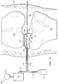
- a reduced pressure therapy system 100 for applying reduced pressure and facilitating the growth of tissue at a tissue site in the body of a patient such as, for example, the knee joint in a leg 101 of the patient comprising the femur 102 and tibia 103. Any portion of the knee joint may have developed a defect that needs repair, for example, a defect 104 in the articular cartilage of the lateral condyle of the femur 102.
- the defect 104 may also be a micro-fracture surgery site as described above where it is desired to regenerate, repair, add or promote growth of new cartilage tissue or any tissue functioning as a structure and support of the body including, without limitation, areola connective tissue, dense connective tissue and cartilage.
- the reduced pressure therapy system 100 also comprises a reduced pressure source 115 for providing a reduced pressure to a bladder 105 comprising a reduced-pressure chamber 106 and a bracing chamber 107 divided by an interior wall 108 within the bladder 105.
- the chambers 106,107 may be separate chambers without the common interior wall 108.
- the bladder 105 is positioned between the bones 102, 103 with the reduced-pressure chamber 106 positioned adjacent the femur 102. It should be understood that the defect 104 could also be in the tibia 103 with the reduced-pressure chamber 106 positioned adjacent such defect in the tibia 103.
- the reduced pressure source 115 is fluidly coupled to the reduced-pressure chamber 106 of the bladder 105 via a first conduit 110.
- the reduced pressure therapy system 100 further comprises a canister 113 fluidly coupled between the reduced pressure source 115 and the reduced pressure chamber 106 of the bladder 105 to collect bodily fluids, such as blood or exudate, that are drawn from the femur 102 via the defect 104.
- a canister 113 fluidly coupled between the reduced pressure source 115 and the reduced pressure chamber 106 of the bladder 105 to collect bodily fluids, such as blood or exudate, that are drawn from the femur 102 via the defect 104.
- the reduced-pressure source 115 and the canister 113 are integrated into a single housing structure.
- reduced pressure generally refers to a pressure that is less than the ambient pressure at a tissue site that is subjected to treatment. In most cases, this reduced pressure will be less than the atmospheric pressure of the location at which the patient is located.
- vacuum and “negative pressure” may be used to describe the pressure applied to the tissue site, the actual pressure applied to the tissue site may be significantly greater than the pressure normally associated with a complete vacuum. Consistent with this nomenclature, an increase in reduced pressure or vacuum pressure refers to a relative reduction of absolute pressure, while a decrease in reduced pressure or vacuum pressure refers to a relative increase of absolute pressure.
- the system 100 further comprises a first fluid supply 111 that is fluidly coupled to the bracing chamber 107 of the bladder 105 via a second conduit 112.
- the first fluid supply 111 provides a bracing substance to the bracing chamber 107 via the second conduit 112 to fill the bracing chamber 107 under a positive pressure so that the bracing chamber 107 expands and exerts a positive force on the tibia 103 and surrounding tissue as well as the interior wall 108 of the bladder 105.
- the positive pressure applied to the bracing substance in the bracing chamber 107 is sufficient to allow the bracing chamber 107 to conform to the shape and contours of the tibia 103 and surrounding tissue while simultaneously providing a cushion between the femur 102 and the tibia 103 without collapsing.
- the bracing chamber 107 of the bladder 105 may comprise multiple chambers to achieve the desired cushioning and conformance with the tibia 103 and surrounding tissue.
- the bracing substance may be a gas or a liquid such as, for example, a highly viscous compressible material such as a putty, slurry, or colloid.
- Both the first conduit 110 and the second conduit 112 may be coupled to the bladder 105 via connectors 114 and 116, respectively. Both conduits 110, 112 may be coated with an anti-coagulant to prevent a build-up of bodily fluids or blood within the conduits.
- the term “coupled” includes direct coupling or indirect coupling via a separate object. The term “coupled” also encompasses two or more components that are continuous with one another by virtue of each of the components formed from the same piece of material. Also, the term “coupled” may include chemical, mechanical, thermal, or electrical coupling. Fluid coupling means that fluid is in communication between the designated parts or locations.
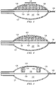
- the bladder 105 is shown with and without a reduced pressure applied to the reduced-pressure chamber 106 in FIGS. 2B and 2A , respectively.
- the bladder 105 comprises two exterior walls including a reduced-pressure exterior wall 126 which forms the external surface of the reduced-pressure chamber 106 and bracing exterior wall 127 which forms the external wall of the bracing chamber 107.
- the reduced-pressure exterior wall 126 has a generally circular opening 128 which is shaped to fit the perimeter of the defect 104.
- the bladder 105 further comprises a manifold structure 120 that may be two separate manifold components 120a, 120b positioned on both sides of the defect 104 in the femur 102 as shown in FIG.
- the manifold structure 120 may be sealed against the inside surface the reduced-pressure exterior wall 126.
- the manifold structure 120 may have a height somewhat less than the distance between the reduced-pressure exterior wall 126 and the interior wall 108 so that it is slightly suspended over the interior wall 108 when the reduced pressure chamber 106 is not under pressure.
- the reduced-pressure exterior wall 126 collapses to the position shown as 126' with the manifold structure 120 being forced against the interior wall 108 and forming a seal with a portion of the interior wall 108 to concentrate the reduced pressure on the defect 104.
- the portion of the interior wall 108 defined by the inner diameter of the manifold structure 120 may form a slightly dimpled portion 108' as a result of the reduced pressure being applied through the manifold structure 120.
- the dimpled portion 108' of the interior wall 108 and the inner surface 129 of the manifold structure 120 define a cavity 130 that is positioned adjacent the defect 104.
- the reduced-pressure exterior wall 126 provides a seal around the defect 104 for applying the reduced pressure directly to the defect 104 via the opening 128 in the reduced-pressure exterior wall 126.
- the manifold structure 120 also serves to prevent the exterior wall 126 from collapsing against the interior wall 108, allowing the reduced pressure to continue to be applied to the defect 104 in the femur 102.
- the manifold structure 120 whether a single piece or multiple manifold components 120a and 120b, is selected to provide adequate structural support within the reduced-pressure chamber 106 between the femur 102 and the interior wall 108 while still functioning within the reduced-pressure chamber 106 as forming a part of the cavity 130.
- the interior wall 108 is substantially impermeable to block the transmission of fluids including both liquids and gases.
- the interior wall 108 may be a single layer of material or multiple layers of material depending on the manufacturing process of the bladder 105.
- the manifold structure 120 may form a slight dimpled portion 108' as a result of the reduced pressure being applied to the reduced-pressure chamber 106 and the positive pressure being applied to the bracing chamber 107, the interior wall 108 is substantially inflexible to reduce the amount of bending or flexing in response to the pressures being applied on both sides.
- Such materials may include, for example, fiberglass, metals, rubbers, or plastics alone or in combination.
- the interior wall 108 must be sufficiently inflexible or rigid to ensure that the cavity 130 does not collapse against the defect 104 when the reduced pressure and bracing pressure are applied to the bladder 105.
- the exterior walls 126, 127 are also fabricated from an impermeable material to substantially block the transmission of fluids. Additionally, the exterior walls 126, 127 must be sufficiently thick to withstand the tensile stress and compressive stress created by the application of the reduced pressure to the reduced-pressure chamber 106 and the positive pressure to the bracing chamber 107, respectively. Consequently, the exterior walls 126, 127 may be formed of multiple layers of material having the same or different properties. For example, the exterior walls 126, 127 may have a first layer that is impermeable to fluids and second layer that has sufficient flexibility and structural support when under pressure. These characteristics are of course dependent upon the specific materials used to fabricate the exterior walls 126, 127 of the bladder 105.
- the material used to form the exterior walls 126, 127 may contain one or more elastomers so that they have rubber-like properties.
- the flexible material has elongation rates greater than 100% and a significant amount of resilience.
- the resilience of a material refers to the material's ability to recover from an elastic deformation.
- elastomers include, but are not limited to, natural rubbers, polyisoprene, styrene butadiene rubber, chloroprene rubber, polybutadiene, nitrile rubber, butyl rubber, ethylene propylene rubber, ethylene propylene diene monomer, chlorosulfonated polyethylene, polysulfide rubber, polyurethane, and silicones.
- Elastomers may also include, but are not limited to, polyurethane elastomers, including elastomers based on both aromatic and aliphatic isocyanates; flexible polyolefins, including flexible polyethylene and polypropylene homopolymers and copolymers; styrenic thermoplastic elastomers; polyamide elastomers; polyamide-ether elastomers; ester-ether or ester-ester elastomers; flexible ionomers; thermoplastic vulcanizates; flexible poly(vinyl chloride) homopolymers and copolymers; flexible acrylic polymers; and blends and alloys of these, such as poly(vinyl chloride) alloys like poly(vinyl chloride)-polyurethane alloys.
- polyurethane elastomers including elastomers based on both aromatic and aliphatic isocyanates
- flexible polyolefins including flexible polyethylene and polypropylene homopolymers and copo
- the exterior walls 126, 127 may also include, but are not limited to, polyester-polyurethanes, polyether-polyurethanes, and polycarbonate-polyurethanes.
- the different elastomeric materials described above may be combined as blends to form the exterior walls 126, 127 in one layer, or alternatively, may be formed as separate layers.
- the exterior walls 126, 127 may be formed of bioinert materials, i.e., materials which do not elicit a strong immunological reaction against the material and are not toxic, but which do not degrade within the body over time.
- the manifold structure 120 distributes the reduced pressure within the reduced-pressure chamber 106 to the defect 104 while providing support as a spacer between the interior wall 108 and the reduced-pressure exterior wall 126 in the collapsed position 126' as shown in FIG. 2B .
- the manifold structure 120 comprises an open-cell foam material that includes a plurality of cells fluidly coupled to each other to form a plurality of flow channels within the manifold structure 120.
- the cells and flow channels may be of uniform shape and size or may include a pattern or random variations to more precisely direct the flow of fluids through the flow channels within the manifold structure 120.
- the manifold structure 120 is a foam material that may be either hydrophobic or hydrophilic.
- the manifold structure 120 is an open-cell, reticulated polyurethane foam such as GranuFoam ® dressing available from Kinetic Concepts, Inc. of San Antonio, Texas.
- the manifold structure 120 also functions to wick fluid out of the cavity 130, while continuing to provide reduced pressure to the defect 104 as a manifold.
- the wicking properties of the manifold structure 120 draw fluid away from the defect 104 by capillary flow or other wicking mechanisms.
- hydrophilic foam is a polyvinyl alcohol, open-cell foam such as V.A.C. WhiteFoam ® dressing available from Kinetic Concepts, Inc. of San Antonio, Texas.
- Other hydrophilic foams may include those made from polyether.
- Other foams that may exhibit hydrophilic characteristics include hydrophobic foams that have been treated or coated to provide hydrophilicity.
- the manifold structure 120 may be constructed from bioresorbable materials that do not have to be removed from a patient's body after the defect 104 has been repaired and the reduced-pressure chamber 106 fully collapses.
- Suitable bioresorbable materials may include, without limitation, a polymeric blend of polylactic acid (PLA) and polyglycolic acid (PGA).
- the polymeric blend may also include, without limitation, polycarbonates, polyfumarates, and capralactones.
- the manifold structure 120 may further serve as a scaffold for new cell-growth, or a scaffold material may be used in conjunction with the manifold structure 120 to promote cell-growth.
- a scaffold is a substance or structure used to enhance or promote the growth of cells or formation of tissue, such as a three-dimensional porous structure that provides a template for cell growth.
- Illustrative examples of scaffold materials include synthetic, biosynthetic, and biologic material such as calcium phosphate, collagen, PLA/PGA, coral hydroxy apatites, carbonates, autologous tissue, or processed allograft or xenograft materials.
- the manifold structure 120 may also include a closed-cell material to provide sufficient support within the reduced-pressure chamber 106 to prevent the exterior wall 126 collapsing prematurely on the interior wall 108.
- the closed-cell material also contains a plurality of cells, but the majority of these cells are not fluidly coupled to each other with flow channels so that they provide a more solid structural support within the reduced-pressure chamber 106.
- the closed-cell material is sufficiently dense to maintain the three-dimensional shape of the manifold structure 120 to provide structural support within the reduced-pressure chamber 106 and to prevent the open-cells from collapsing and cutting off the flow of reduced pressure through the flow channels.
- the size of the cells in the manifold structure 120 must be sufficiently large to facilitate the communication of fluids through the plurality of cells in the manifold structure 120, but sufficiently small with lower porosities to provide structural support within the reduced-pressure chamber 106. While the size of the cells in the manifold structure 120 is not exactly known, it is between about 100 microns at the low end to maintain sufficient permeability allowing air and fluids to move therethrough when under pressure, and about 1500 microns on the high end to maintain sufficient structural support for the femur 102. Further, the size and number of cells in the manifold structure 120 affect the porosity of the manifold structure 120.
- the porosity percentage should be at least about 50% to ensure that the manifold structure 120 continues to facilitate fluid flow through the open-cell structure.
- the porosity percentage should be no greater than about 85% to ensure that the manifold structure provides sufficient structural support.
- the porosity of the manifold structure 120 should be in a range of about 50% to about 85%.
- the interior wall 108 is sufficiently rigid to prevent the dimpled portion 108' of the interior wall 108 and the inner diameter surface 129 of the manifold structure 120 from contacting the defect 104.
- Material may be positioned within the cavity 130 adjacent the defect 104 that promotes healing of the defect 104, or provides additional structural support, or provides a barrier to isolate the reduced-pressure chamber 106 from the defect 104, or all the foregoing.
- additional manifold material may be placed within the cavity 130 to provide additional structural support in a similar fashion as the manifold structure 120 described above, and/or to function as scaffold material to promote healing of the defect 104.
- a manifold structure may also function as a scaffold material to promote healing of the defect 104.
- Such a manifold structure may be bioresorbable and left in place after the reduced pressure delivery system 100 is removed.
- the shape of the manifold structure 120 may be any that prevents the exterior wall 126 from collapsing against the interior wall 108 within the reduced-pressure chamber 106 when being subjected to a reduced pressure.
- the manifold structure 120 may support only a portion of the exterior wall 126 of the reduced-pressure chamber 106 as illustrated in FIG. 2A .
- a manifold structure 320 may fill most of the reduced-pressure chamber 106 to support the entire inner portion of the exterior wall 126 of the reduced-pressure chamber 106 as shown in FIG. 3 .
- the reduced-pressure exterior wall 126 does not collapse to the position shown as 126' as shown in FIG. 2B .
- the manifold structure 320 is still forced against the interior wall 108 to form the cavity 130 positioned adjacent the defect 104. Consequently, the reduced-pressure exterior wall 126 provides a seal around the defect 104 for applying the reduced pressure directly to the defect 104 via the opening 128 in the reduced-pressure exterior wall 126 as shown in FIG. 2B .
- This particular embodiment provides more structural support to the reduced-pressure chamber 106 of the bladder 105 if, for example, more support is needed for the femur 102 as preferred in some embodiments.
- the manifold structure 320 may also include a portion that functions as scaffold material to promote healing of the defect 104.
- the scaffold portion may be sized to fill a defect that is a gap or void in the femur 102 and may be a separate or integrated component of the manifold structure 320.
- the scaffold portion of the manifold structure 320 may be bioresorbable and left in place after reduced-pressure delivery system 10 is removed. Referring more specifically to FIG. 4 , such a manifold structure 420 is shown that includes a scaffold component 422 to promote regeneration of the defect 104 while at the same time providing additional structural support between the femur 102 and the interior wall 108 of the bladder 105.
- the manifold structure 420 may be constructed of similar foam material as the manifold structure 120 as described above.
- the scaffold component 422 comprises primarily open-cell material to facilitate fluid communication between the manifold structure 420 and the defect 104. As such, the scaffold component 422 serves as an additional manifold to more efficiently distribute reduced pressure across the entire surface of the defect 104, while at the same time providing some cushion between the femur 102 and the interior wall 108 of the bladder 105.
- the scaffold component 422 of the manifold structure 420 may be coated or infused with growth factors, cells or nutrients to promote the growth of cells and/or the regeneration of cartilage tissue.
- the scaffold component 422 may also be self-seeded whereby the reduced pressure pulls cells from the surrounding bone or other body tissues into the cells of the scaffold component 422 where they may grow and/or form new tissue. Further, the scaffold component 422 may be seeded with cells ex vivo, prior to application.
- the size of the cells in the scaffold component 422 must be sufficiently large to maintain fluid flow through the plurality of cells in the structure, but sufficiently small with lower porosities to provide enough structural support within the scaffold component 422 to ensure that the flow channels therein do not collapse significantly and the scaffold component 422 retains its shape to function as a scaffold when a reduced pressure is applied to the reduced-pressure chamber 106.
- the scaffold component 422 in a reduced pressure environment may have the open cell structure that collapses to about 10%, about 20%, about 40%, about 80%, or any range therebetween to avoid disrupting or significantly altering fluid communication within the scaffold component 422.
- the cell size and porosity of the scaffold component would be in the same range as described above for the manifold structure 120.
- the scaffold component 422 may be constructed as a separate component that contacts a surface of the manifold structure 120 with a loose interface that allows the scaffold component 422 to separate easily from the manifold structure 120 when the bladder 105 is removed from the femur 102. Thus, the scaffold component 422 remains in place at the site of the repaired defect 104 when the bladder 105 is removed.
- the scaffold component 422 may be constructed so that it adheres to the surface of the manifold structure 120 using, for example, an adhesive that causes the scaffold component 422 to remain attached to the manifold structure 120 when the bladder 105 removed from the femur 102. Thus, the scaffold component 422 does not remain in place at the site of the repaired defect 104 when the bladder 105 is removed.
- the scaffold component 422 When the scaffold component 422 is intended to be removed with the manifold structure 420, they may be fabricated as a unitary component (not shown) with dual porosities such that they function in the same manner as described above.
- Such unitary components with dual porosities are disclosed and described in U.S. Patent No. 6,695,823 and International Application No. PCT/US2008/000596 (International Publication No. WO 2008/091521 A2 ).
- the scaffold component 422 may be constructed from materials including synthetics, biosynthetics, or biologics such as calcium phosphate, collagen, PLA/PGA, coral hydroxy apatites, carbonates, autologous tissue, or processed allograft or xenograft materials.
- the scaffold component 422 may also be formed of bioinert materials, i.e., materials which do not elicit a strong immunological reaction against the material nor are toxic, but which do not degrade within the body over time.
- the scaffold component 422 is formed of biocompatible materials, i.e., materials which do not elicit a strong immunological reaction against the material nor are toxic, and which degrade into non-toxic, non-immunogenic chemical species which are removed from the body by excretion or metabolism.
- the scaffold component 422 is formed of biodegradable materials, i.e., materials which are enzymatically or chemically degraded in vivo into simpler chemical species.
- the scaffold component 422 is made of biocompatible and/or biodegradable materials.
- the scaffold component 422 may remain at the site of the defect 104 even if the bladder 105 is removed from the knee joint.
- the scaffold component 422 should be constructed of materials having appropriate dimensions for the site and sufficient strength to support new tissue growth.
- the biocompatible and/or biodegradable materials may include, but is not limited to, lactide, poly(lactide) (PLA), glycolide polymers, poly(glycolic acid) (PGA), poly(lactide-co-glycolide) (PLGA), ethylene glycol/lactide copolymers, polycaprolactone, poly (p-dioxanone), polyhydroxybutyrate, polyurethanes, polyphosphazenes, poly(ethylene glycol)-poly(lactide-co-glycolide) co-polymer, polyhydroxyacids, polycarbonates, polyamides, polyanhydrides, polyamino acids, polyortho esters, polyacetals, degradable polycyanoacrylates, polycarbonates, polyfumarates, degradable polyurethanes, proteins such as albumin, collagen, fibrin, synthetic and natural polyamino acids, polysaccharides such as alginate, heparin, other naturally occurring biodegradable
- the materials may be designed to degrade within a desired time frame.
- the desired degradation time frame is one to two weeks.
- the desired degradation time frame is between one month and one year.
- the desired degradation time is greater than a year.
- scaffold component 422 made of biocompatible or biodegradable materials may degrade in a manner related to the molecular weights of the materials used to make the scaffold component 422.
- a higher molecular weight material may result in scaffold component 422 that retains its structural integrity for longer periods of time, while lower molecular weights result in faster degradation with shorter scaffold life.
- the cavity 130 may include a material positioned within the void adjacent the defect 104 that promotes healing of the defect 104, provides additional structural support, and provides a barrier to isolate the reduced-pressure chamber 106 from the defect 104.
- FIG. 5 illustrates another embodiment of the reduced-pressure chamber 106 comprising a barrier material 520 that covers the opening in the exterior wall 126 and closes the cavity 130.
- the barrier material 520 may be attached to the manifold structure 120 and/or attached to the exterior wall 126 of the reduced-pressure chamber 106.
- the barrier material 520 directly contacts the surface of the defect 104 when the cavity 130 is placed adjacent the defect 104.
- the barrier material 520 may comprise one or more pieces of material that covers a portion, or all, of the exterior wall 126 of the reduced-pressure chamber 106.
- the barrier material 520 is preferably fabricated from a material that allows the reduced-pressure chamber 106 to be in fluid communication with the defect 104 while isolating the defect 104 from direct communication with the cavity 130.
- the barrier material 520 may be, for example, a mesh, a sieve, a screen, or a solid sheet with spaces or a punched pattern.
- the barrier material 520 may have sufficient strength to provide additional structural support for the knee joint.
- the reduced pressure therapy system 100 may further comprise pressure sensors 140, 142 operably connected to the first and second conduits 110, 112 to measure the reduced pressure and the bracing pressure, respectively.
- the system further includes a control unit 145 electrically connected to the pressure sensors 140, 142, the reduced pressure source 115, and the first fluid supply 111 that provides the bracing fluids through the second conduit 112 to the bracing chamber 107.
- the pressure sensor 140 measures the reduced pressure of the reduced-pressure chamber 106, and also may indicate whether the first conduit 110 is occluded with blood or other bodily fluids.
- the pressure sensor 140 also provides feedback to control unit 145 which regulates the reduced-pressure therapy being applied by the reduced-pressure source 115 through the first conduit 110 to the reduced-pressure chamber 106.
- the pressure sensor 142 measures the positive pressure of the bracing fluid being applied by the first fluid supply 111 through the second conduit 112 to the bracing chamber 107.
- the pressure sensor 142 also provides feedback to the control unit 145 which regulates positive pressure therapy being applied by the reduced-pressure source 115 to the bracing chamber 107.
- the control unit 145 also balances the relative amount of reduced pressure and positive pressure being applied to the reduced-pressure chamber 106 and the bracing chamber 107, respectively, so that sufficient pressures are being applied to both the femur 102 and the tibia 103, respectively, and the interior wall 108 as described above.
- the reduced-pressure therapy system 100 may also comprise a second fluid supply 150 fluidly coupled to the first conduit 110 via third conduit 152 and operatively connected to the control unit 145.
- the second fluid supply 150 may be used to deliver growth and/or healing agents to the defect 104 including, without limitation, an antibacterial agent, an antiviral agent, a cell-growth promotion agent, an irrigation fluid, or other chemically active agents.
- the system 100 further comprises a first valve 154 positioned in the third conduit 152 to control the flow of fluid therethrough, and a second valve 156 positioned in the first conduit 110 between the reduced-pressure source 115 and the juncture between the first conduit 110 and the third conduit 152 to control the flow of reduced pressure.
- the control unit 145 is electrically connected to the second fluid supply 150 and the first and second valves 154, 156 to control the delivery of reduced pressure and/or fluid from the second fluid supply 150 to the reduced-pressure chamber 106 as required by the particular therapy being administered to the patient.
- the second fluid supply 150 may deliver the liquids as indicated above, but may also deliver air to the reduced-pressure chamber 106 to promote healing and facilitate drainage at the site of the defect 104.
- the independent paths of fluid communication provided by the conduits 110, 112, and 152 may be accomplished in a number of different ways, including that of providing a single, multi-lumen tube with two or more lumens.
- a person of ordinary skill in the art will recognize that the pressure sensors 140, 142, valves 154, 156, and other components associated with the conduits could also be similarly associated with a particular lumen in the delivery tube if a multi-lumen tube is used.
- additional lumens may be provided to separately introduce air or other fluids to the site of the defect 104, including, without limitation, an antibacterial agent, an antiviral agent, a cell-growth promotion agent, an irrigation fluid, or other chemically active agents.
- the exterior walls 126, 127 of the bladder 105 are flexible as described above.
- the bladder 105 may be collapsed or flattened as shown more specifically in FIG. 2C as a flattened bladder 205 and preferably flattened at the edge where the interior wall 108 intersects the exterior walls 126, 127, the edges of which are indicated by the reference number 708 shown by the dashed line in FIG. 7A .
- the flattened bladder 205 is then folded or rolled as shown in FIG. 7B into a substantially tubular shape as indicated by reference numeral 705.
- the reduced-pressure chamber 106 and the bracing chamber 107 may not share a common wall such as the interior wall 108, but may have separate walls.
- the rolled bladder 705 along with the first and second conduits 110, 112 may then be inserted into a delivery catheter 710 as shown in FIG. 7C .
- the delivery catheter 710 has a distal end 712 that tapers so that the delivery catheter 710 may be surgically or percutaneously inserted in the knee joint between the femur 102 and the tibia 103 to deliver the rolled bladder 705 to the desired lateral site adjacent the defect 104 as shown in FIG. 8 .
- the delivery catheter 710 When percutaneously inserted, the delivery catheter 710 may be inserted through a sterile insertion sheath (not shown) that penetrates the skin tissue of the patient.
- the distal end 712 of the delivery catheter 710 is tapered to assist movement of the delivery catheter 710 through the tissues of the knee joint, but must also have a sufficiently large opening in the tapered distal end 712 to allow the rolled bladder 705 to be pushed out of the delivery catheter 710 and inserted into the knee joint of the patient.
- the delivery catheter 710 may be made of any material that provides sufficient strength to allow the delivery catheter 710 to be pushed through the bodily tissues into the knee joint of the patient.
- the materials of the delivery catheter 710 should be bioinert, therefore not causing injury, toxic or immunologic reaction to the surrounding body tissues.
- Materials of interest includes, but are not limited to, polyimide, polyamide, PBAXTM, polyethylene, fluoropolymer, polyurethane, polyisoprene, nylon, steel and the like. It is also contemplated that in one alternate embodiment, the materials of the delivery catheter 710 will allow the delivery catheter 710 an amount of flex. Further, in one embodiment, outer diameter of the delivery catheter 710 is coated with agents to prevent the tube from adhering to the body tissues.
- the tubing may be coated with heparin, anticoagulants, anti-fibrogens, anti-adherents, anti-thrombinogens or hydrophilic substances.
- the outer diameter and/or interior diameter of the delivery catheter 710 are coated with a lubricant agent, including but not limited to, silicone, hydrophilic coating, Surmodics ® lubricants, and the like.
- the distal end 712 of the delivery catheter 710 is pushed through the skin 702 of the leg 101 of the patient until it is positioned adjacent the knee joint.
- the first and second conduits 110 and 112, collectively referred to as the conduits 719, may then be manually pushed to force the rolled bladder 705 through the delivery catheter 710 and out of the distal end 712 of the delivery catheter 710 until the rolled bladder 705 is laterally positioned at the desired site adjacent the defect 104.
- the femur 102 with the defect 104 may have already undergone microfracture surgery.
- microfracture surgery generally includes the medical practitioner, i.e ., surgeon or nurse practitioner, who cuts a small incision on the skin 702 exterior to the knee joint.
- a long thin scope (not shown), for example, an arthroscope, may be inserted through the skin 702 and through the body tissues 703 to the site of the defect 104. If necessary, calcified cartilage is removed.
- the surgeon may then create microfractures, i . e., small holes, scrapes, tears, in the femur 102 near the defective cartilage, i.e., the defect 104.
- the delivery catheter 710 may be inserted through the same skin opening 702 and body tissue 703 path formed by the scope. In another embodiment, a separate, additional skin opening may be formed for receiving the delivery catheter 710. After the distal end 712 of the delivery catheter 710 is delivered to the surgical site, the conduits 719 may be mechanically or manually pushed so that the rolled bladder 705 moves through and out the distal end 712 of the delivery catheter 710 to be positioned at the desired site adjacent the defect 104.
- the delivery catheter 710 may be removed from the patient's leg 101.
- the rolled bladder 705 may then be unrolled in the opposite direction shown in FIG. 7B to a relatively flattened shape with the cavity 130 positioned adjacent the defect 104.
- a positive pressure is applied by the bracing fluid to the bracing chamber 107 so that it expands and exerts a force on the tibia 103 and on the interior wall 108 as described above while at the same time applying a reduced pressure to the reduced-pressure chamber 106 so that the opening 128 in the reduced-pressure chamber 106 (see FIG.
- Application of the positive pressure to the bracing chamber 107 also forces the interior wall 108 and the manifold structure 120 against the distal end of the femur to force the opening 128 of the reduced-pressure chamber 106 against the defect 104 after which a reduced pressure is applied to the defect 104 via the cavity 130.
- the cavity 130 may be filled with the scaffold component 422 or covered by a barrier material 520 closing the opening of the cavity 130.
- a reduced pressure is ultimately applied via the opening 128 in the reduced-pressure chamber 106 to the defect 104 so that the reduced pressure increases the seepage of blood and bone marrow through the fractures created by the microfracturing surgery to draw blood and other stimulatory agents to the defect site.
- the reduced pressure therapy or treatment applied to the defect 104 depends on the size and shape of the defect 104 and various other factors known in the art.
- the reduced pressure being applied may be continuous, variable at a specific frequency, or generally cyclical over time depending on the desired treatment for the patient and the characteristics of the defect 104.
- the opening 128 in the reduced-pressure chamber 106 not only applies the reduced pressure directly to the defect 104, but also mitigates the removal of the sinovial fluid from the knee joint while the reduced pressure is being applied to the defect 104.
- FIG. 9 another embodiment of a bladder 905 is shown that is substantially similar to the bladder 105 described above including the same components identified with similar reference numerals.
- the bladder 905 comprises a reduced-pressure chamber 906 and a bracing chamber 907 separated by an interior wall 908, each chamber having an exterior wall 926 and 927, respectively, all as described above with respect to the bladder 105.
- the reduced-pressure chamber 906 also includes a manifold structure 920 that functions in the same fashion as the manifold structure 420 described above that fills most of the reduced-pressure chamber 906.
- the reduced-pressure chamber 906 and the bracing chamber 907 each comprise an elongated conduit 914 and 916, respectively, fluidly coupled to each chamber and extending from the bladder 905 through the skin of the leg 101 of the patient.
- the elongated conduits 914, 916 may be an integrated portion of the reduced-pressure exterior wall 126 and the bracing exterior wall 127, respectively, with the interior wall 908 extending therebetween.
- the manifold structure 920 extends through and substantially fills the elongated conduit 914 of the reduced-pressure chamber 906.
- the distal ends of the elongated conduits 914, 916 may be fluidly coupled to the first conduit 110 and the second conduit 112, respectively, for providing a reduced pressure to the reduced-pressure chamber 906 and bracing fluid under a positive pressure to the bracing chamber 907 which function in the same manner as described above.
- the portion of the manifold structure 920 extending through the elongated conduit 914 of the reduced-pressure chamber 906 provides additional structural support for the reduced-pressure chamber 906 so that the bladder 905 can be more easily flattened or rolled as described above to facilitate insertion of the bladder 905 into the delivery catheter 710 (not shown).
- the bladder 105 further comprises an elongated tab 109 extending from the end of the bladder 105 opposite the side that is fluidly coupled to the first and second conduits 110, 112 (see also FIG. 1A ).
- the elongated tab 109 is useful for guiding and manipulating the bladder 105 to the desired lateral position adjacent the defect 104 as described above. More specifically, the arthroscope may be inserted completely through the knee joint to create a path for the elongated tab 109 which would be inserted in advance of the bladder 105 through the delivery catheter 710 and ultimately extend out the other side of the patient's leg 101 as shown in FIG. 1A .
- the elongated tab 109 may be affixed to the exterior wall 126 of the reduced-pressure chamber 106 to facilitate positioning of the opening 128 in the reduced-pressure chamber 106 adjacent the defect 104.
- the elongated tab 109 may be affixed to the bladder 105 either prior to being inserted into the knee joint, or at any later point during the surgery to facilitate positioning of the bladder 105.
- the elongated tab may be inserted from the opposite side of the knee joint through the incisional pathway and into the distal end 712 of the delivery catheter 710 where it can be affixed to or screwed into the bladder 105.
- the elongated tab 109 then can be used to pull the bladder 105 through the delivery catheter 710 instead of using the first and second conduits 110, 112 to push the bladder 105 to the desired position.
- the bladder 105 may also include a sheath 119 covering the first and second conduits 110, 112 and affixed directly to the bladder 105.
- the sheath 119 may be constructed of a material for providing additional strength to the first and second conduits 110, 112 for pushing the bladder 105 into the desired position adjacent the defect 104 as described above.
- the sheath 119 and the elongated tab 109 may also be a single continuous piece of material as shown in FIG. 10B to further facilitate pushing and/or pulling the bladder 105 to the desired lateral position adjacent the defect 104 and positioning the opening 128 in the reduced-pressure chamber 106 so that it fully contacts the defect 104.
- the design and materials of the bladder chamber, delivery tubes, and the like may be any contemplated in other embodiments of the application and are dependent upon numerous factors, including, for example, the location and size of the tissue site, the pressure of the bracing chamber to maintain the position of the opening 128 in the reduced-pressure chamber 106 against the defect 104. It is contemplated further that for all of the embodiments described herein, the number, size and type of bladder chambers may vary, depending upon the shape of the bone that contains the one or more tissue sites. As such, to better expand the bracing chambers and seal the one or more supportive foam structures to the bone comprising the tissue site, the bladder chamber may have two or more bracing chambers.
Landscapes
- Health & Medical Sciences (AREA)
- Life Sciences & Earth Sciences (AREA)
- Surgery (AREA)
- Public Health (AREA)
- Animal Behavior & Ethology (AREA)
- General Health & Medical Sciences (AREA)
- Veterinary Medicine (AREA)
- Engineering & Computer Science (AREA)
- Orthopedic Medicine & Surgery (AREA)
- Heart & Thoracic Surgery (AREA)
- Biomedical Technology (AREA)
- Chemical & Material Sciences (AREA)
- Nuclear Medicine, Radiotherapy & Molecular Imaging (AREA)
- Medical Informatics (AREA)
- Molecular Biology (AREA)
- Epidemiology (AREA)
- Transplantation (AREA)
- Oral & Maxillofacial Surgery (AREA)
- Medicinal Chemistry (AREA)
- Materials Engineering (AREA)
- Dispersion Chemistry (AREA)
- Dermatology (AREA)
- Cardiology (AREA)
- Vascular Medicine (AREA)
- Bioinformatics & Cheminformatics (AREA)
- Pulmonology (AREA)
- Pharmacology & Pharmacy (AREA)
- Chemical Kinetics & Catalysis (AREA)
- Organic Chemistry (AREA)
- Child & Adolescent Psychology (AREA)
- Biophysics (AREA)
- Physical Education & Sports Medicine (AREA)
- Anesthesiology (AREA)
- Hematology (AREA)
- General Chemical & Material Sciences (AREA)
- Prostheses (AREA)
- Surgical Instruments (AREA)
- Meat, Egg Or Seafood Products (AREA)
Applications Claiming Priority (2)
| Application Number | Priority Date | Filing Date | Title |
|---|---|---|---|
| US14159308P | 2008-12-30 | 2008-12-30 | |
| PCT/US2009/069031 WO2010078118A2 (en) | 2008-12-30 | 2009-12-21 | Reduced pressure augmentation of microfracture procedures for cartilage repair |
Publications (3)
| Publication Number | Publication Date |
|---|---|
| EP2370009A2 EP2370009A2 (en) | 2011-10-05 |
| EP2370009A4 EP2370009A4 (en) | 2015-06-24 |
| EP2370009B1 true EP2370009B1 (en) | 2017-08-02 |
Family
ID=42285847
Family Applications (1)
| Application Number | Title | Priority Date | Filing Date |
|---|---|---|---|
| EP09836993.7A Active EP2370009B1 (en) | 2008-12-30 | 2009-12-21 | Reduced pressure augmentation of microfracture for cartilage repair |
Country Status (13)
| Country | Link |
|---|---|
| US (3) | US8702711B2 (zh) |
| EP (1) | EP2370009B1 (zh) |
| JP (1) | JP5607071B2 (zh) |
| KR (1) | KR20110107357A (zh) |
| CN (1) | CN102271600B (zh) |
| AU (1) | AU2009333066B2 (zh) |
| BR (1) | BRPI0918196A2 (zh) |
| CA (1) | CA2746515A1 (zh) |
| MX (1) | MX2011007082A (zh) |
| RU (1) | RU2011127676A (zh) |
| SG (1) | SG172010A1 (zh) |
| TW (1) | TW201029691A (zh) |
| WO (1) | WO2010078118A2 (zh) |
Families Citing this family (5)
| Publication number | Priority date | Publication date | Assignee | Title |
|---|---|---|---|---|
| EP2723286B2 (en) | 2011-06-24 | 2021-10-13 | KCI Licensing, Inc. | Reduced-pressure dressings employing tissue-fixation elements |
| WO2014088790A2 (en) | 2012-12-06 | 2014-06-12 | Kci Licensing, Inc. | Adaptable wound drainage system |
| JP6295182B2 (ja) * | 2014-11-05 | 2018-03-14 | グンゼ株式会社 | 組織再生基材 |
| KR102621037B1 (ko) | 2021-08-17 | 2024-01-03 | 전남대학교산학협력단 | 연골 재생용 지지체 |
| US20230211049A1 (en) * | 2021-09-20 | 2023-07-06 | Industry Foundation Of Chonnam National University | Scaffolds for cartilage regeneration and method for treatment of cartilage defects using the same |
Family Cites Families (187)
| Publication number | Priority date | Publication date | Assignee | Title |
|---|---|---|---|---|
| US1355846A (en) * | 1920-02-06 | 1920-10-19 | David A Rannells | Medical appliance |
| US2547758A (en) | 1949-01-05 | 1951-04-03 | Wilmer B Keeling | Instrument for treating the male urethra |
| US2632443A (en) | 1949-04-18 | 1953-03-24 | Eleanor P Lesher | Surgical dressing |
| GB692578A (en) | 1949-09-13 | 1953-06-10 | Minnesota Mining & Mfg | Improvements in or relating to drape sheets for surgical use |
| US2682873A (en) | 1952-07-30 | 1954-07-06 | Johnson & Johnson | General purpose protective dressing |
| NL189176B (nl) | 1956-07-13 | 1900-01-01 | Hisamitsu Pharmaceutical Co | Pleister op basis van een synthetische rubber. |
| US2969057A (en) | 1957-11-04 | 1961-01-24 | Brady Co W H | Nematodic swab |
| US3066672A (en) | 1960-09-27 | 1962-12-04 | Jr William H Crosby | Method and apparatus for serial sampling of intestinal juice |
| US3367332A (en) | 1965-08-27 | 1968-02-06 | Gen Electric | Product and process for establishing a sterile area of skin |
| US3520300A (en) | 1967-03-15 | 1970-07-14 | Amp Inc | Surgical sponge and suction device |
| US3568675A (en) | 1968-08-30 | 1971-03-09 | Clyde B Harvey | Fistula and penetrating wound dressing |
| US3682180A (en) | 1970-06-08 | 1972-08-08 | Coilform Co Inc | Drain clip for surgical drain |
| BE789293Q (fr) | 1970-12-07 | 1973-01-15 | Parke Davis & Co | Pansement medico-chirugical pour brulures et lesions analogues |
| US3826254A (en) | 1973-02-26 | 1974-07-30 | Verco Ind | Needle or catheter retaining appliance |
| DE2527706A1 (de) | 1975-06-21 | 1976-12-30 | Hanfried Dr Med Weigand | Einrichtung zum einleiten von kontrastmittel in einen kuenstlichen darmausgang |
| DE2640413C3 (de) | 1976-09-08 | 1980-03-27 | Richard Wolf Gmbh, 7134 Knittlingen | Katheter-Überwachungsgerät |
| NL7710909A (nl) | 1976-10-08 | 1978-04-11 | Smith & Nephew | Samengestelde hechtstrook. |
| GB1562244A (en) | 1976-11-11 | 1980-03-05 | Lock P M | Wound dressing materials |
| US4080970A (en) | 1976-11-17 | 1978-03-28 | Miller Thomas J | Post-operative combination dressing and internal drain tube with external shield and tube connector |
| US4139004A (en) | 1977-02-17 | 1979-02-13 | Gonzalez Jr Harry | Bandage apparatus for treating burns |
| US4184510A (en) | 1977-03-15 | 1980-01-22 | Fibra-Sonics, Inc. | Valued device for controlling vacuum in surgery |
| US4165748A (en) | 1977-11-07 | 1979-08-28 | Johnson Melissa C | Catheter tube holder |
| US4256109A (en) | 1978-07-10 | 1981-03-17 | Nichols Robert L | Shut off valve for medical suction apparatus |
| SE414994B (sv) | 1978-11-28 | 1980-09-01 | Landstingens Inkopscentral | Venkateterforband |
| BR7908937A (pt) | 1978-12-06 | 1981-06-30 | Svedman Paul | Dispositivo para tratamento de tecidos,por exemplo,pele |
| US4266545A (en) | 1979-04-06 | 1981-05-12 | Moss James P | Portable suction device for collecting fluids from a closed wound |
| US4284079A (en) | 1979-06-28 | 1981-08-18 | Adair Edwin Lloyd | Method for applying a male incontinence device |
| US4261363A (en) | 1979-11-09 | 1981-04-14 | C. R. Bard, Inc. | Retention clips for body fluid drains |
| US4569348A (en) | 1980-02-22 | 1986-02-11 | Velcro Usa Inc. | Catheter tube holder strap |
| US4480638A (en) | 1980-03-11 | 1984-11-06 | Eduard Schmid | Cushion for holding an element of grafted skin |
| US4297995A (en) | 1980-06-03 | 1981-11-03 | Key Pharmaceuticals, Inc. | Bandage containing attachment post |
| US4333468A (en) | 1980-08-18 | 1982-06-08 | Geist Robert W | Mesentery tube holder apparatus |
| US4465485A (en) | 1981-03-06 | 1984-08-14 | Becton, Dickinson And Company | Suction canister with unitary shut-off valve and filter features |
| US4392853A (en) | 1981-03-16 | 1983-07-12 | Rudolph Muto | Sterile assembly for protecting and fastening an indwelling device |
| US4373519A (en) | 1981-06-26 | 1983-02-15 | Minnesota Mining And Manufacturing Company | Composite wound dressing |
| US4392858A (en) | 1981-07-16 | 1983-07-12 | Sherwood Medical Company | Wound drainage device |
| US4419097A (en) | 1981-07-31 | 1983-12-06 | Rexar Industries, Inc. | Attachment for catheter tube |
| AU550575B2 (en) | 1981-08-07 | 1986-03-27 | Richard Christian Wright | Wound drainage device |
| SE429197B (sv) | 1981-10-14 | 1983-08-22 | Frese Nielsen | Anordning for behandling av sar |
| DE3146266A1 (de) | 1981-11-21 | 1983-06-01 | B. Braun Melsungen Ag, 3508 Melsungen | Kombinierte vorrichtung fuer eine medizinische saugdrainage |
| US4551139A (en) | 1982-02-08 | 1985-11-05 | Marion Laboratories, Inc. | Method and apparatus for burn wound treatment |
| US4475909A (en) | 1982-05-06 | 1984-10-09 | Eisenberg Melvin I | Male urinary device and method for applying the device |
| EP0100148B1 (en) | 1982-07-06 | 1986-01-08 | Dow Corning Limited | Medical-surgical dressing and a process for the production thereof |
| NZ206837A (en) | 1983-01-27 | 1986-08-08 | Johnson & Johnson Prod Inc | Thin film adhesive dressing:backing material in three sections |
| US4548202A (en) | 1983-06-20 | 1985-10-22 | Ethicon, Inc. | Mesh tissue fasteners |
| US4540412A (en) | 1983-07-14 | 1985-09-10 | The Kendall Company | Device for moist heat therapy |
| US4543100A (en) | 1983-11-01 | 1985-09-24 | Brodsky Stuart A | Catheter and drain tube retainer |
| US4525374A (en) | 1984-02-27 | 1985-06-25 | Manresa, Inc. | Treating hydrophobic filters to render them hydrophilic |
| GB2157958A (en) | 1984-05-03 | 1985-11-06 | Ernest Edward Austen Bedding | Ball game net support |
| US4897081A (en) | 1984-05-25 | 1990-01-30 | Thermedics Inc. | Percutaneous access device |
| US5215522A (en) | 1984-07-23 | 1993-06-01 | Ballard Medical Products | Single use medical aspirating device and method |
| GB8419745D0 (en) | 1984-08-02 | 1984-09-05 | Smith & Nephew Ass | Wound dressing |
| US4872450A (en) | 1984-08-17 | 1989-10-10 | Austad Eric D | Wound dressing and method of forming same |
| US4826494A (en) | 1984-11-09 | 1989-05-02 | Stryker Corporation | Vacuum wound drainage system |
| US4655754A (en) | 1984-11-09 | 1987-04-07 | Stryker Corporation | Vacuum wound drainage system and lipids baffle therefor |
| US4605399A (en) | 1984-12-04 | 1986-08-12 | Complex, Inc. | Transdermal infusion device |
| US5037397A (en) | 1985-05-03 | 1991-08-06 | Medical Distributors, Inc. | Universal clamp |
| US4640688A (en) | 1985-08-23 | 1987-02-03 | Mentor Corporation | Urine collection catheter |
| US4710165A (en) | 1985-09-16 | 1987-12-01 | Mcneil Charles B | Wearable, variable rate suction/collection device |
| US4758220A (en) | 1985-09-26 | 1988-07-19 | Alcon Laboratories, Inc. | Surgical cassette proximity sensing and latching apparatus |
| US4733659A (en) | 1986-01-17 | 1988-03-29 | Seton Company | Foam bandage |
| EP0256060A1 (en) | 1986-01-31 | 1988-02-24 | OSMOND, Roger L. W. | Suction system for wound and gastro-intestinal drainage |
| US4838883A (en) | 1986-03-07 | 1989-06-13 | Nissho Corporation | Urine-collecting device |
| JPS62281965A (ja) | 1986-05-29 | 1987-12-07 | テルモ株式会社 | カテ−テルおよびカテ−テル用固定部材 |
| GB8621884D0 (en) | 1986-09-11 | 1986-10-15 | Bard Ltd | Catheter applicator |
| GB2195255B (en) | 1986-09-30 | 1991-05-01 | Vacutec Uk Limited | Apparatus for vacuum treatment of an epidermal surface |
| US4743232A (en) | 1986-10-06 | 1988-05-10 | The Clinipad Corporation | Package assembly for plastic film bandage |
| DE3634569A1 (de) | 1986-10-10 | 1988-04-21 | Sachse Hans E | Kondomkatheter, ein harnroehrenkatheter zur verhinderung von aufsteigenden infektionen |
| JPS63135179A (ja) | 1986-11-26 | 1988-06-07 | 立花 俊郎 | 薬物の経皮投与具 |
| GB8628564D0 (en) | 1986-11-28 | 1987-01-07 | Smiths Industries Plc | Anti-foaming agent suction apparatus |
| GB8706116D0 (en) | 1987-03-14 | 1987-04-15 | Smith & Nephew Ass | Adhesive dressings |
| US4787888A (en) | 1987-06-01 | 1988-11-29 | University Of Connecticut | Disposable piezoelectric polymer bandage for percutaneous delivery of drugs and method for such percutaneous delivery (a) |
| US4863449A (en) | 1987-07-06 | 1989-09-05 | Hollister Incorporated | Adhesive-lined elastic condom cathether |
| US5176663A (en) | 1987-12-02 | 1993-01-05 | Pal Svedman | Dressing having pad with compressibility limiting elements |
| US4906240A (en) | 1988-02-01 | 1990-03-06 | Matrix Medica, Inc. | Adhesive-faced porous absorbent sheet and method of making same |
| US4985019A (en) | 1988-03-11 | 1991-01-15 | Michelson Gary K | X-ray marker |
| US5053050A (en) * | 1988-04-29 | 1991-10-01 | Samuel Itay | Compositions for repair of cartilage and bone |
| GB8812803D0 (en) | 1988-05-28 | 1988-06-29 | Smiths Industries Plc | Medico-surgical containers |
| US4919654A (en) | 1988-08-03 | 1990-04-24 | Kalt Medical Corporation | IV clamp with membrane |
| US5000741A (en) | 1988-08-22 | 1991-03-19 | Kalt Medical Corporation | Transparent tracheostomy tube dressing |
| DE69017479T2 (de) | 1989-01-16 | 1995-07-13 | Roussel Uclaf | Azabicycloheptenderivate und ihre Salze, Verfahren zu ihrer Herstellung, ihre Verwendung als Arzneimittel und diese enthaltende Zubereitungen. |
| GB8906100D0 (en) | 1989-03-16 | 1989-04-26 | Smith & Nephew | Laminates |
| US5261893A (en) | 1989-04-03 | 1993-11-16 | Zamierowski David S | Fastening system and method |
| US5100396A (en) | 1989-04-03 | 1992-03-31 | Zamierowski David S | Fluidic connection system and method |
| US4969880A (en) | 1989-04-03 | 1990-11-13 | Zamierowski David S | Wound dressing and treatment method |
| US5527293A (en) | 1989-04-03 | 1996-06-18 | Kinetic Concepts, Inc. | Fastening system and method |
| US5358494A (en) | 1989-07-11 | 1994-10-25 | Svedman Paul | Irrigation dressing |
| JP2719671B2 (ja) | 1989-07-11 | 1998-02-25 | 日本ゼオン株式会社 | 創傷被覆材 |
| US5232453A (en) | 1989-07-14 | 1993-08-03 | E. R. Squibb & Sons, Inc. | Catheter holder |
| GB2235877A (en) | 1989-09-18 | 1991-03-20 | Antonio Talluri | Closed wound suction apparatus |
| US5134994A (en) | 1990-02-12 | 1992-08-04 | Say Sam L | Field aspirator in a soft pack with externally mounted container |
| US5092858A (en) | 1990-03-20 | 1992-03-03 | Becton, Dickinson And Company | Liquid gelling agent distributor device |
| JP2941918B2 (ja) | 1990-09-19 | 1999-08-30 | テルモ株式会社 | 秤量装置 |
| US5811094A (en) * | 1990-11-16 | 1998-09-22 | Osiris Therapeutics, Inc. | Connective tissue regeneration using human mesenchymal stem cell preparations |
| US5149331A (en) | 1991-05-03 | 1992-09-22 | Ariel Ferdman | Method and device for wound closure |
| US5278100A (en) | 1991-11-08 | 1994-01-11 | Micron Technology, Inc. | Chemical vapor deposition technique for depositing titanium silicide on semiconductor wafers |
| US5645081A (en) | 1991-11-14 | 1997-07-08 | Wake Forest University | Method of treating tissue damage and apparatus for same |
| US5636643A (en) | 1991-11-14 | 1997-06-10 | Wake Forest University | Wound treatment employing reduced pressure |
| US5279550A (en) | 1991-12-19 | 1994-01-18 | Gish Biomedical, Inc. | Orthopedic autotransfusion system |
| US5167613A (en) | 1992-03-23 | 1992-12-01 | The Kendall Company | Composite vented wound dressing |
| FR2690617B1 (fr) | 1992-04-29 | 1994-06-24 | Cbh Textile | Pansement adhesif transparent. |
| DE4306478A1 (de) | 1993-03-02 | 1994-09-08 | Wolfgang Dr Wagner | Drainagevorrichtung, insbesondere Pleuradrainagevorrichtung, und Drainageverfahren |
| US6241747B1 (en) | 1993-05-03 | 2001-06-05 | Quill Medical, Inc. | Barbed Bodily tissue connector |
| US5342376A (en) | 1993-05-03 | 1994-08-30 | Dermagraphics, Inc. | Inserting device for a barbed tissue connector |
| US5344415A (en) | 1993-06-15 | 1994-09-06 | Deroyal Industries, Inc. | Sterile system for dressing vascular access site |
| WO1995005083A1 (en) * | 1993-08-13 | 1995-02-23 | Smith & Nephew Richards Inc | Microporous polymeric foams and microtextured surfaces |
| US5437651A (en) | 1993-09-01 | 1995-08-01 | Research Medical, Inc. | Medical suction apparatus |
| WO1995020362A1 (en) * | 1994-01-26 | 1995-08-03 | Reiley Mark A | Improved inflatable device for use in surgical protocol relating to fixation of bone |
| US20030032963A1 (en) * | 2001-10-24 | 2003-02-13 | Kyphon Inc. | Devices and methods using an expandable body with internal restraint for compressing cancellous bone |
| US5549584A (en) | 1994-02-14 | 1996-08-27 | The Kendall Company | Apparatus for removing fluid from a wound |
| US5723331A (en) * | 1994-05-05 | 1998-03-03 | Genzyme Corporation | Methods and compositions for the repair of articular cartilage defects in mammals |
| US5607388A (en) | 1994-06-16 | 1997-03-04 | Hercules Incorporated | Multi-purpose wound dressing |
| US5556375A (en) | 1994-06-16 | 1996-09-17 | Hercules Incorporated | Wound dressing having a fenestrated base layer |
| US5664270A (en) | 1994-07-19 | 1997-09-09 | Kinetic Concepts, Inc. | Patient interface system |
| ZA956968B (en) | 1994-08-22 | 1996-03-29 | Kinetic Concepts Inc | Wound drainage equipment |
| DE29504378U1 (de) | 1995-03-15 | 1995-09-14 | Mtg Medizinisch Tech Geraeteba | Elektronisch geregelte Niedervakuumpumpe für die Thorax- und Wunddrainage |
| US6123727A (en) * | 1995-05-01 | 2000-09-26 | Massachusetts Institute Of Technology | Tissue engineered tendons and ligaments |
| GB9523253D0 (en) | 1995-11-14 | 1996-01-17 | Mediscus Prod Ltd | Portable wound treatment apparatus |
| DE69623112T2 (de) | 1996-01-16 | 2003-05-08 | Matrix Biotechnologies Inc | Einheit zur knorpelreparatur |
| US5786219A (en) * | 1996-10-28 | 1998-07-28 | Molecular Probes, Inc. | Microspheres with fluorescent spherical zones |
| US7346945B2 (en) * | 1996-11-18 | 2008-03-25 | Kci Licensing, Inc. | Bariatric treatment system and related methods |
| US7468075B2 (en) * | 2001-05-25 | 2008-12-23 | Conformis, Inc. | Methods and compositions for articular repair |
| US5977204A (en) | 1997-04-11 | 1999-11-02 | Osteobiologics, Inc. | Biodegradable implant material comprising bioactive ceramic |
| DE19722075C1 (de) * | 1997-05-27 | 1998-10-01 | Wilhelm Dr Med Fleischmann | Vorrichtung zur Applikation von Wirkstoffen an einer Wundoberfläche |
| US7759538B2 (en) * | 1997-05-27 | 2010-07-20 | Wilhelm Fleischmann | Process and device for application of active substances to a wound surface |
| DE69840171D1 (de) | 1997-05-30 | 2008-12-11 | Osteobiologics Inc | Faserverstärkte,poröse,biologisch abbaubare implantatvorrichtung |
| US7214202B1 (en) * | 1997-07-28 | 2007-05-08 | Kci Licensing, Inc. | Therapeutic apparatus for treating ulcers |
| US6135116A (en) | 1997-07-28 | 2000-10-24 | Kci Licensing, Inc. | Therapeutic method for treating ulcers |
| GB9719520D0 (en) | 1997-09-12 | 1997-11-19 | Kci Medical Ltd | Surgical drape and suction heads for wound treatment |
| AU755496B2 (en) | 1997-09-12 | 2002-12-12 | Kci Licensing, Inc. | Surgical drape and suction head for wound treatment |
| US6071267A (en) | 1998-02-06 | 2000-06-06 | Kinetic Concepts, Inc. | Medical patient fluid management interface system and method |
| US6763836B2 (en) * | 1998-06-02 | 2004-07-20 | Arthrocare Corporation | Methods for electrosurgical tendon vascularization |
| US6958149B2 (en) * | 1998-10-06 | 2005-10-25 | Stryker Corporation | Repair of larynx, trachea, and other fibrocartilaginous tissues |
| US6488643B1 (en) | 1998-10-08 | 2002-12-03 | Kci Licensing, Inc. | Wound healing foot wrap |
| US6767334B1 (en) * | 1998-12-23 | 2004-07-27 | Kci Licensing, Inc. | Method and apparatus for wound treatment |
| AU2713800A (en) | 1998-12-23 | 2000-07-31 | Kci Licensing, Inc. | Method and apparatus for wound treatment |
| US6727224B1 (en) * | 1999-02-01 | 2004-04-27 | Genetics Institute, Llc. | Methods and compositions for healing and repair of articular cartilage |
| US6287316B1 (en) | 1999-03-26 | 2001-09-11 | Ethicon, Inc. | Knitted surgical mesh |
| US20070021697A1 (en) * | 2004-07-26 | 2007-01-25 | Kci Licensing, Inc. | System and method for use of agent in combination with subatmospheric tissue treatment |
| US6994702B1 (en) * | 1999-04-06 | 2006-02-07 | Kci Licensing, Inc. | Vacuum assisted closure pad with adaptation for phototherapy |
| US7799004B2 (en) | 2001-03-05 | 2010-09-21 | Kci Licensing, Inc. | Negative pressure wound treatment apparatus and infection identification system and method |
| US6856821B2 (en) * | 2000-05-26 | 2005-02-15 | Kci Licensing, Inc. | System for combined transcutaneous blood gas monitoring and vacuum assisted wound closure |
| US6695823B1 (en) | 1999-04-09 | 2004-02-24 | Kci Licensing, Inc. | Wound therapy device |
| JP5153974B2 (ja) | 1999-04-09 | 2013-02-27 | ケーシーアイ ライセンシング インコーポレイテッド | 創傷部治療装置 |
| GB9909301D0 (en) * | 1999-04-22 | 1999-06-16 | Kci Medical Ltd | Wound treatment apparatus employing reduced pressure |
| US6991643B2 (en) | 2000-12-20 | 2006-01-31 | Usgi Medical Inc. | Multi-barbed device for retaining tissue in apposition and methods of use |
| US6491693B1 (en) * | 1999-12-07 | 2002-12-10 | Michael Lytinas | Method of promoting osteogenesis by application of a vacuum to affected bone areas, and device for same |
| DE60103248T2 (de) | 2000-02-24 | 2005-06-16 | Venetec International, Inc., San Diego | Universelles katheterbefestigungssystem |
| US7070584B2 (en) * | 2001-02-20 | 2006-07-04 | Kci Licensing, Inc. | Biocompatible wound dressing |
| US7700819B2 (en) | 2001-02-16 | 2010-04-20 | Kci Licensing, Inc. | Biocompatible wound dressing |
| US6540705B2 (en) | 2001-02-22 | 2003-04-01 | Core Products International, Inc. | Ankle brace providing upper and lower ankle adjustment |
| US7108683B2 (en) | 2001-04-30 | 2006-09-19 | Kci Licensing, Inc | Wound therapy and tissue management system and method with fluid differentiation |
| US7645269B2 (en) | 2001-04-30 | 2010-01-12 | Kci Licensing, Inc. | Gradient wound treatment system and method |
| US7004915B2 (en) | 2001-08-24 | 2006-02-28 | Kci Licensing, Inc. | Negative pressure assisted tissue treatment system |
| MXPA01011542A (es) * | 2001-11-13 | 2003-05-22 | Alcon Inc | Regeneracion del cartilago articular da°ado por la osteoartritis de grado i y ii, mediante la aplicacion intra-articular de una mezcla de hialuronato de sodio y de condroitin sulfato en un vehiculo de gel. |
| US7468192B2 (en) * | 2002-03-22 | 2008-12-23 | Histogenics Corporation | Method for repair of cartilage lesions |
| US20030225347A1 (en) * | 2002-06-03 | 2003-12-04 | Argenta Louis C. | Directed tissue growth employing reduced pressure |
| US6944702B1 (en) | 2002-06-26 | 2005-09-13 | Emc Corporation | Data storage system |
| US7351250B2 (en) * | 2002-08-21 | 2008-04-01 | Kci Licensing, Inc. | Circumferential medical closure device and method |
| US20040039391A1 (en) * | 2002-08-23 | 2004-02-26 | Argenta Louis C. | Bone treatment employing reduced pressure |
| US7666134B2 (en) | 2002-09-28 | 2010-02-23 | Kci Licensing, Inc. | System and method for transplantation of dermal tissue |
| EP1578477B2 (en) | 2002-12-31 | 2020-05-06 | KCI Licensing, Inc. | A dressing assembly for a closed wound or incision |
| US7976519B2 (en) | 2002-12-31 | 2011-07-12 | Kci Licensing, Inc. | Externally-applied patient interface system and method |
| US6951553B2 (en) * | 2002-12-31 | 2005-10-04 | Kci Licensing, Inc | Tissue closure treatment system and method with externally-applied patient interface |
| US6982298B2 (en) * | 2003-01-10 | 2006-01-03 | The Cleveland Clinic Foundation | Hydroxyphenyl cross-linked macromolecular network and applications thereof |
| US20040175690A1 (en) | 2003-03-03 | 2004-09-09 | Kci Licensing, Inc. | Tissue harvesting device and method |
| US20040197375A1 (en) | 2003-04-02 | 2004-10-07 | Alireza Rezania | Composite scaffolds seeded with mammalian cells |
| US7169151B1 (en) * | 2003-04-10 | 2007-01-30 | Kci Licensing, Inc. | Bone regeneration device for long bones, and method of use |
| US7186224B2 (en) * | 2003-04-28 | 2007-03-06 | Scimed Life Systems, Inc. | Side attaching guidewire torque device |
| PL1641914T3 (pl) * | 2003-06-27 | 2017-01-31 | DePuy Synthes Products, Inc. | Komórki pochodzące z poporodowej tkanki łożyska oraz sposoby uzyskiwania i zastosowania tych komórek |
| ATE550067T1 (de) | 2003-07-22 | 2012-04-15 | Kci Licensing Inc | Negativdruck-wundbehandlungskompresse |
| WO2005089127A2 (en) * | 2004-03-05 | 2005-09-29 | The Trustees Of Columbia University In The City Of New York | Polymer-ceramic-hydrogel composite scaffold for osteochondral repair |
| WO2007067685A2 (en) | 2005-12-06 | 2007-06-14 | Kci Licensing Inc | Wound exudate removal and isolation system |
| AU2007212480B2 (en) | 2006-02-06 | 2010-04-29 | Solventum Intellectual Properties Company | Systems and methods for improved connection to wound dressings in conjunction with reduced pressure wound treatment systems |
| CN101460205B (zh) | 2006-03-14 | 2011-08-24 | 凯希特许有限公司 | 用于在施用减压治疗期间清洗减压装置的系统 |
| US8267918B2 (en) | 2006-03-14 | 2012-09-18 | Kci Licensing, Inc. | System and method for percutaneously administering reduced pressure treatment using a flowable manifold |
| US20080033324A1 (en) * | 2006-03-14 | 2008-02-07 | Cornet Douglas A | System for administering reduced pressure treatment having a manifold with a primary flow passage and a blockage prevention member |
| US20070276309A1 (en) | 2006-05-12 | 2007-11-29 | Kci Licensing, Inc. | Systems and methods for wound area management |
| US20070276195A1 (en) | 2006-05-12 | 2007-11-29 | Kci Licensing, Inc. | Systems and methods for wound area management |
| US8079991B2 (en) | 2006-06-02 | 2011-12-20 | Kci Licensing Inc. | Wound suction peg apparatus |
| US20070292397A1 (en) | 2006-06-19 | 2007-12-20 | Mcnulty Amy K | Method for the detection and neutralization of bacteria |
| US7876546B2 (en) | 2006-09-19 | 2011-01-25 | Kci Licensing Inc. | Component module for a reduced pressure treatment system |
| US8137354B2 (en) * | 2007-04-25 | 2012-03-20 | Biomet Sports Medicine, Llc | Localized cartilage defect therapy |
| WO2008136998A1 (en) * | 2007-05-01 | 2008-11-13 | The Brigham And Women's Hospital, Inc. | Wound healing device |
| WO2009006226A1 (en) * | 2007-06-29 | 2009-01-08 | Kci Licensing Inc. | Activation of bone and cartilage formation |
| CN201101568Y (zh) * | 2007-10-26 | 2008-08-20 | 祝玉堂 | 内植式骨内血液负压增流装置 |
| GB0723874D0 (en) * | 2007-12-06 | 2008-01-16 | Smith & Nephew | Dressing |
-
2009
- 2009-12-21 CA CA2746515A patent/CA2746515A1/en not_active Abandoned
- 2009-12-21 US US12/643,508 patent/US8702711B2/en active Active
- 2009-12-21 WO PCT/US2009/069031 patent/WO2010078118A2/en active Application Filing
- 2009-12-21 SG SG2011041548A patent/SG172010A1/en unknown
- 2009-12-21 BR BRPI0918196A patent/BRPI0918196A2/pt not_active Application Discontinuation
- 2009-12-21 RU RU2011127676/14A patent/RU2011127676A/ru unknown
- 2009-12-21 KR KR1020117017759A patent/KR20110107357A/ko not_active Application Discontinuation
- 2009-12-21 MX MX2011007082A patent/MX2011007082A/es not_active Application Discontinuation
- 2009-12-21 CN CN2009801533566A patent/CN102271600B/zh active Active
- 2009-12-21 EP EP09836993.7A patent/EP2370009B1/en active Active
- 2009-12-21 AU AU2009333066A patent/AU2009333066B2/en active Active
- 2009-12-21 JP JP2011543619A patent/JP5607071B2/ja active Active
- 2009-12-30 TW TW098146022A patent/TW201029691A/zh unknown
-
2014
- 2014-03-21 US US14/222,271 patent/US9642931B2/en active Active
-
2017
- 2017-04-03 US US15/477,890 patent/US10052132B2/en active Active
Non-Patent Citations (1)
| Title |
|---|
| None * |
Also Published As
| Publication number | Publication date |
|---|---|
| RU2011127676A (ru) | 2013-02-10 |
| CN102271600A (zh) | 2011-12-07 |
| EP2370009A2 (en) | 2011-10-05 |
| US9642931B2 (en) | 2017-05-09 |
| WO2010078118A2 (en) | 2010-07-08 |
| BRPI0918196A2 (pt) | 2016-03-01 |
| US20170224381A1 (en) | 2017-08-10 |
| US20100168746A1 (en) | 2010-07-01 |
| US20140316368A1 (en) | 2014-10-23 |
| AU2009333066A1 (en) | 2011-06-30 |
| TW201029691A (en) | 2010-08-16 |
| US8702711B2 (en) | 2014-04-22 |
| WO2010078118A3 (en) | 2010-10-21 |
| US10052132B2 (en) | 2018-08-21 |
| CA2746515A1 (en) | 2010-07-08 |
| EP2370009A4 (en) | 2015-06-24 |
| MX2011007082A (es) | 2011-07-28 |
| CN102271600B (zh) | 2013-09-18 |
| JP5607071B2 (ja) | 2014-10-15 |
| AU2009333066B2 (en) | 2016-02-18 |
| KR20110107357A (ko) | 2011-09-30 |
| JP2012513830A (ja) | 2012-06-21 |
| SG172010A1 (en) | 2011-07-28 |
Similar Documents
| Publication | Publication Date | Title |
|---|---|---|
| US10052132B2 (en) | Reduced pressure augmentation of microfracture procedures for cartilage repair | |
| AU2017200395B2 (en) | Manifolds, systems, and methods for administering reduced pressure to a subcutaneous tissue site | |
| CA2644898C (en) | System for percutaneously administering reduced pressure treatment using balloon dissection | |
| US8435213B2 (en) | System for administering reduced pressure treatment having a manifold with a primary flow passage and a blockage prevention member | |
| MX2008011738A (es) | Sistema y metodo para purgar un aparato de presion reducida durante la administracion de un tratamiento de presion reducida. | |
| TW200836785A (en) | System for administering reduced pressure teratment having a manifold with a primary flow passage and a blockage prevention member |
Legal Events
| Date | Code | Title | Description |
|---|---|---|---|
| PUAI | Public reference made under article 153(3) epc to a published international application that has entered the european phase |
Free format text: ORIGINAL CODE: 0009012 |
|
| 17P | Request for examination filed |
Effective date: 20110510 |
|
| AK | Designated contracting states |
Kind code of ref document: A2 Designated state(s): AT BE BG CH CY CZ DE DK EE ES FI FR GB GR HR HU IE IS IT LI LT LU LV MC MK MT NL NO PL PT RO SE SI SK SM TR |
|
| DAX | Request for extension of the european patent (deleted) | ||
| A4 | Supplementary search report drawn up and despatched |
Effective date: 20150528 |
|
| RIC1 | Information provided on ipc code assigned before grant |
Ipc: A61B 17/56 20060101AFI20150521BHEP Ipc: A61B 17/88 20060101ALI20150521BHEP Ipc: A61M 25/10 20130101ALI20150521BHEP Ipc: A61B 17/00 20060101ALI20150521BHEP |
|
| RAP1 | Party data changed (applicant data changed or rights of an application transferred) |
Owner name: KCI LICENSING, INC. |
|
| RAP1 | Party data changed (applicant data changed or rights of an application transferred) |
Owner name: KCI LICENSING, INC. |
|
| GRAP | Despatch of communication of intention to grant a patent |
Free format text: ORIGINAL CODE: EPIDOSNIGR1 |
|
| RIC1 | Information provided on ipc code assigned before grant |
Ipc: A61B 17/56 20060101AFI20170127BHEP Ipc: A61M 25/10 20130101ALI20170127BHEP Ipc: A61B 17/88 20060101ALI20170127BHEP Ipc: A61B 17/00 20060101ALI20170127BHEP |
|
| INTG | Intention to grant announced |
Effective date: 20170303 |
|
| GRAS | Grant fee paid |
Free format text: ORIGINAL CODE: EPIDOSNIGR3 |
|
| GRAA | (expected) grant |
Free format text: ORIGINAL CODE: 0009210 |
|
| AK | Designated contracting states |
Kind code of ref document: B1 Designated state(s): AT BE BG CH CY CZ DE DK EE ES FI FR GB GR HR HU IE IS IT LI LT LU LV MC MK MT NL NO PL PT RO SE SI SK SM TR |
|
| RAP1 | Party data changed (applicant data changed or rights of an application transferred) |
Owner name: KCI LICENSING, INC. |
|
| REG | Reference to a national code |
Ref country code: GB Ref legal event code: FG4D |
|
| REG | Reference to a national code |
Ref country code: CH Ref legal event code: EP Ref country code: AT Ref legal event code: REF Ref document number: 913581 Country of ref document: AT Kind code of ref document: T Effective date: 20170815 |
|
| REG | Reference to a national code |
Ref country code: IE Ref legal event code: FG4D |
|
| REG | Reference to a national code |
Ref country code: DE Ref legal event code: R096 Ref document number: 602009047570 Country of ref document: DE |
|
| REG | Reference to a national code |
Ref country code: NL Ref legal event code: MP Effective date: 20170802 |
|
| REG | Reference to a national code |
Ref country code: AT Ref legal event code: MK05 Ref document number: 913581 Country of ref document: AT Kind code of ref document: T Effective date: 20170802 |
|
| REG | Reference to a national code |
Ref country code: LT Ref legal event code: MG4D |
|
| PG25 | Lapsed in a contracting state [announced via postgrant information from national office to epo] |
Ref country code: LT Free format text: LAPSE BECAUSE OF FAILURE TO SUBMIT A TRANSLATION OF THE DESCRIPTION OR TO PAY THE FEE WITHIN THE PRESCRIBED TIME-LIMIT Effective date: 20170802 Ref country code: SE Free format text: LAPSE BECAUSE OF FAILURE TO SUBMIT A TRANSLATION OF THE DESCRIPTION OR TO PAY THE FEE WITHIN THE PRESCRIBED TIME-LIMIT Effective date: 20170802 Ref country code: HR Free format text: LAPSE BECAUSE OF FAILURE TO SUBMIT A TRANSLATION OF THE DESCRIPTION OR TO PAY THE FEE WITHIN THE PRESCRIBED TIME-LIMIT Effective date: 20170802 Ref country code: NL Free format text: LAPSE BECAUSE OF FAILURE TO SUBMIT A TRANSLATION OF THE DESCRIPTION OR TO PAY THE FEE WITHIN THE PRESCRIBED TIME-LIMIT Effective date: 20170802 Ref country code: NO Free format text: LAPSE BECAUSE OF FAILURE TO SUBMIT A TRANSLATION OF THE DESCRIPTION OR TO PAY THE FEE WITHIN THE PRESCRIBED TIME-LIMIT Effective date: 20171102 Ref country code: AT Free format text: LAPSE BECAUSE OF FAILURE TO SUBMIT A TRANSLATION OF THE DESCRIPTION OR TO PAY THE FEE WITHIN THE PRESCRIBED TIME-LIMIT Effective date: 20170802 Ref country code: FI Free format text: LAPSE BECAUSE OF FAILURE TO SUBMIT A TRANSLATION OF THE DESCRIPTION OR TO PAY THE FEE WITHIN THE PRESCRIBED TIME-LIMIT Effective date: 20170802 |
|
| PG25 | Lapsed in a contracting state [announced via postgrant information from national office to epo] |
Ref country code: BG Free format text: LAPSE BECAUSE OF FAILURE TO SUBMIT A TRANSLATION OF THE DESCRIPTION OR TO PAY THE FEE WITHIN THE PRESCRIBED TIME-LIMIT Effective date: 20171102 Ref country code: LV Free format text: LAPSE BECAUSE OF FAILURE TO SUBMIT A TRANSLATION OF THE DESCRIPTION OR TO PAY THE FEE WITHIN THE PRESCRIBED TIME-LIMIT Effective date: 20170802 Ref country code: IS Free format text: LAPSE BECAUSE OF FAILURE TO SUBMIT A TRANSLATION OF THE DESCRIPTION OR TO PAY THE FEE WITHIN THE PRESCRIBED TIME-LIMIT Effective date: 20171202 Ref country code: GR Free format text: LAPSE BECAUSE OF FAILURE TO SUBMIT A TRANSLATION OF THE DESCRIPTION OR TO PAY THE FEE WITHIN THE PRESCRIBED TIME-LIMIT Effective date: 20171103 Ref country code: ES Free format text: LAPSE BECAUSE OF FAILURE TO SUBMIT A TRANSLATION OF THE DESCRIPTION OR TO PAY THE FEE WITHIN THE PRESCRIBED TIME-LIMIT Effective date: 20170802 Ref country code: PL Free format text: LAPSE BECAUSE OF FAILURE TO SUBMIT A TRANSLATION OF THE DESCRIPTION OR TO PAY THE FEE WITHIN THE PRESCRIBED TIME-LIMIT Effective date: 20170802 |
|
| PG25 | Lapsed in a contracting state [announced via postgrant information from national office to epo] |
Ref country code: RO Free format text: LAPSE BECAUSE OF FAILURE TO SUBMIT A TRANSLATION OF THE DESCRIPTION OR TO PAY THE FEE WITHIN THE PRESCRIBED TIME-LIMIT Effective date: 20170802 Ref country code: CZ Free format text: LAPSE BECAUSE OF FAILURE TO SUBMIT A TRANSLATION OF THE DESCRIPTION OR TO PAY THE FEE WITHIN THE PRESCRIBED TIME-LIMIT Effective date: 20170802 Ref country code: DK Free format text: LAPSE BECAUSE OF FAILURE TO SUBMIT A TRANSLATION OF THE DESCRIPTION OR TO PAY THE FEE WITHIN THE PRESCRIBED TIME-LIMIT Effective date: 20170802 |
|
| REG | Reference to a national code |
Ref country code: DE Ref legal event code: R097 Ref document number: 602009047570 Country of ref document: DE |
|
| PG25 | Lapsed in a contracting state [announced via postgrant information from national office to epo] |
Ref country code: SM Free format text: LAPSE BECAUSE OF FAILURE TO SUBMIT A TRANSLATION OF THE DESCRIPTION OR TO PAY THE FEE WITHIN THE PRESCRIBED TIME-LIMIT Effective date: 20170802 Ref country code: SK Free format text: LAPSE BECAUSE OF FAILURE TO SUBMIT A TRANSLATION OF THE DESCRIPTION OR TO PAY THE FEE WITHIN THE PRESCRIBED TIME-LIMIT Effective date: 20170802 Ref country code: IT Free format text: LAPSE BECAUSE OF FAILURE TO SUBMIT A TRANSLATION OF THE DESCRIPTION OR TO PAY THE FEE WITHIN THE PRESCRIBED TIME-LIMIT Effective date: 20170802 Ref country code: EE Free format text: LAPSE BECAUSE OF FAILURE TO SUBMIT A TRANSLATION OF THE DESCRIPTION OR TO PAY THE FEE WITHIN THE PRESCRIBED TIME-LIMIT Effective date: 20170802 |
|
| PLBE | No opposition filed within time limit |
Free format text: ORIGINAL CODE: 0009261 |
|
| STAA | Information on the status of an ep patent application or granted ep patent |
Free format text: STATUS: NO OPPOSITION FILED WITHIN TIME LIMIT |
|
| REG | Reference to a national code |
Ref country code: DE Ref legal event code: R082 Ref document number: 602009047570 Country of ref document: DE Representative=s name: SIMMONS & SIMMONS LLP, DE |
|
| 26N | No opposition filed |
Effective date: 20180503 |
|
| REG | Reference to a national code |
Ref country code: CH Ref legal event code: PL |
|
| PG25 | Lapsed in a contracting state [announced via postgrant information from national office to epo] |
Ref country code: SI Free format text: LAPSE BECAUSE OF FAILURE TO SUBMIT A TRANSLATION OF THE DESCRIPTION OR TO PAY THE FEE WITHIN THE PRESCRIBED TIME-LIMIT Effective date: 20170802 |
|
| REG | Reference to a national code |
Ref country code: IE Ref legal event code: MM4A |
|
| PG25 | Lapsed in a contracting state [announced via postgrant information from national office to epo] |
Ref country code: LU Free format text: LAPSE BECAUSE OF NON-PAYMENT OF DUE FEES Effective date: 20171221 Ref country code: MT Free format text: LAPSE BECAUSE OF NON-PAYMENT OF DUE FEES Effective date: 20171221 |
|
| REG | Reference to a national code |
Ref country code: FR Ref legal event code: ST Effective date: 20180831 |
|
| REG | Reference to a national code |
Ref country code: BE Ref legal event code: MM Effective date: 20171231 |
|
| PG25 | Lapsed in a contracting state [announced via postgrant information from national office to epo] |
Ref country code: IE Free format text: LAPSE BECAUSE OF NON-PAYMENT OF DUE FEES Effective date: 20171221 Ref country code: FR Free format text: LAPSE BECAUSE OF NON-PAYMENT OF DUE FEES Effective date: 20180102 |
|
| PG25 | Lapsed in a contracting state [announced via postgrant information from national office to epo] |
Ref country code: LI Free format text: LAPSE BECAUSE OF NON-PAYMENT OF DUE FEES Effective date: 20171231 Ref country code: CH Free format text: LAPSE BECAUSE OF NON-PAYMENT OF DUE FEES Effective date: 20171231 Ref country code: BE Free format text: LAPSE BECAUSE OF NON-PAYMENT OF DUE FEES Effective date: 20171231 |
|
| PG25 | Lapsed in a contracting state [announced via postgrant information from national office to epo] |
Ref country code: MC Free format text: LAPSE BECAUSE OF FAILURE TO SUBMIT A TRANSLATION OF THE DESCRIPTION OR TO PAY THE FEE WITHIN THE PRESCRIBED TIME-LIMIT Effective date: 20170802 Ref country code: HU Free format text: LAPSE BECAUSE OF FAILURE TO SUBMIT A TRANSLATION OF THE DESCRIPTION OR TO PAY THE FEE WITHIN THE PRESCRIBED TIME-LIMIT; INVALID AB INITIO Effective date: 20091221 |
|
| PG25 | Lapsed in a contracting state [announced via postgrant information from national office to epo] |
Ref country code: CY Free format text: LAPSE BECAUSE OF NON-PAYMENT OF DUE FEES Effective date: 20170802 |
|
| PG25 | Lapsed in a contracting state [announced via postgrant information from national office to epo] |
Ref country code: MK Free format text: LAPSE BECAUSE OF FAILURE TO SUBMIT A TRANSLATION OF THE DESCRIPTION OR TO PAY THE FEE WITHIN THE PRESCRIBED TIME-LIMIT Effective date: 20170802 |
|
| PG25 | Lapsed in a contracting state [announced via postgrant information from national office to epo] |
Ref country code: TR Free format text: LAPSE BECAUSE OF FAILURE TO SUBMIT A TRANSLATION OF THE DESCRIPTION OR TO PAY THE FEE WITHIN THE PRESCRIBED TIME-LIMIT Effective date: 20170802 |
|
| PG25 | Lapsed in a contracting state [announced via postgrant information from national office to epo] |
Ref country code: PT Free format text: LAPSE BECAUSE OF FAILURE TO SUBMIT A TRANSLATION OF THE DESCRIPTION OR TO PAY THE FEE WITHIN THE PRESCRIBED TIME-LIMIT Effective date: 20170802 |
|
| REG | Reference to a national code |
Ref country code: GB Ref legal event code: 732E Free format text: REGISTERED BETWEEN 20201203 AND 20201209 |
|
| REG | Reference to a national code |
Ref country code: DE Ref legal event code: R081 Ref document number: 602009047570 Country of ref document: DE Owner name: SOLVENTUM INTELLECTUAL PROPERTIES CO. (N.D.GES, US Free format text: FORMER OWNER: KCI LICENSING, INC., SAN ANTONIO, TEX., US Ref country code: DE Ref legal event code: R082 Ref document number: 602009047570 Country of ref document: DE Representative=s name: SIMMONS & SIMMONS LLP, DE Ref country code: DE Ref legal event code: R081 Ref document number: 602009047570 Country of ref document: DE Owner name: 3M INNOVATIVE PROPERTIES COMPANY, ST. PAUL, US Free format text: FORMER OWNER: KCI LICENSING, INC., SAN ANTONIO, TEX., US |
|
| PGFP | Annual fee paid to national office [announced via postgrant information from national office to epo] |
Ref country code: GB Payment date: 20231121 Year of fee payment: 15 |
|
| PGFP | Annual fee paid to national office [announced via postgrant information from national office to epo] |
Ref country code: DE Payment date: 20231121 Year of fee payment: 15 |
|
| REG | Reference to a national code |
Ref country code: GB Ref legal event code: 732E Free format text: REGISTERED BETWEEN 20240208 AND 20240214 |
|
| REG | Reference to a national code |
Ref country code: DE Ref legal event code: R081 Ref document number: 602009047570 Country of ref document: DE Owner name: SOLVENTUM INTELLECTUAL PROPERTIES CO. (N.D.GES, US Free format text: FORMER OWNER: 3M INNOVATIVE PROPERTIES COMPANY, ST. PAUL, MN, US |