EP2369580B1 - Pin for a stringed instrument - Google Patents
Pin for a stringed instrument Download PDFInfo
- Publication number
- EP2369580B1 EP2369580B1 EP10157648.6A EP10157648A EP2369580B1 EP 2369580 B1 EP2369580 B1 EP 2369580B1 EP 10157648 A EP10157648 A EP 10157648A EP 2369580 B1 EP2369580 B1 EP 2369580B1
- Authority
- EP
- European Patent Office
- Prior art keywords
- string
- section
- machine head
- collar
- vortex
- Prior art date
- Legal status (The legal status is an assumption and is not a legal conclusion. Google has not performed a legal analysis and makes no representation as to the accuracy of the status listed.)
- Not-in-force
Links
Images
Classifications
-
- G—PHYSICS
- G10—MUSICAL INSTRUMENTS; ACOUSTICS
- G10D—STRINGED MUSICAL INSTRUMENTS; WIND MUSICAL INSTRUMENTS; ACCORDIONS OR CONCERTINAS; PERCUSSION MUSICAL INSTRUMENTS; AEOLIAN HARPS; SINGING-FLAME MUSICAL INSTRUMENTS; MUSICAL INSTRUMENTS NOT OTHERWISE PROVIDED FOR
- G10D3/00—Details of, or accessories for, stringed musical instruments, e.g. slide-bars
- G10D3/14—Tuning devices, e.g. pegs, pins, friction discs or worm gears
-
- G—PHYSICS
- G10—MUSICAL INSTRUMENTS; ACOUSTICS
- G10D—STRINGED MUSICAL INSTRUMENTS; WIND MUSICAL INSTRUMENTS; ACCORDIONS OR CONCERTINAS; PERCUSSION MUSICAL INSTRUMENTS; AEOLIAN HARPS; SINGING-FLAME MUSICAL INSTRUMENTS; MUSICAL INSTRUMENTS NOT OTHERWISE PROVIDED FOR
- G10D3/00—Details of, or accessories for, stringed musical instruments, e.g. slide-bars
-
- G—PHYSICS
- G10—MUSICAL INSTRUMENTS; ACOUSTICS
- G10G—REPRESENTATION OF MUSIC; RECORDING MUSIC IN NOTATION FORM; ACCESSORIES FOR MUSIC OR MUSICAL INSTRUMENTS NOT OTHERWISE PROVIDED FOR, e.g. SUPPORTS
- G10G7/00—Other auxiliary devices or accessories, e.g. conductors' batons or separate holders for resin or strings
Definitions
- the present invention relates to a vortex for a stringed instrument having the features of the preamble of claim 1. It further relates to a provided with such a vortex string instrument itself.
- the whirling wooden pegs or metal pegs on which the string ends are rolled up are called vertebrae.
- the tension of the strings can be changed and the instrument can be tuned with it.
- the vertebrae are adjustable by means of appropriate handling gear stages, to be able to cause a fine tuning.
- whirls are waves on which a string end can be wound up for a tightening and thus higher mood, or for relaxing and thus for deeper voices.
- a string to a vertebra typically has, in a winding section, a through hole or slot through which the string end is guided and subsequently fixed by knotting or entangling.
- This type of fixing a string end to the vortex is complicated to perform and there is - especially in non-professional execution - the risk of loosening or yielding of the end of the string and, consequently, a detuning of the instrument.
- a node attached here for fixing the end of the string or a similar twisted construct occupies a considerable space, so that the space required for vertebrae is comparatively large.
- the above-mentioned disadvantages also have an effect, in particular, on such vertebrae which, as part of automated tuning systems, adjust the tension of the strings by motor-driven means.
- it depends on a high strength of the specified end of the string for a reproducible tuning of the instrument.
- for a motor-driven adjustment as uniform as possible winding the string end on the vertebrae of advantage which is difficult for a one-sided arranged on a vertebra node or a similar loop, since there the string always on the through the node or the Loop formed increase accumulates.
- a vortex for a stringed instrument which can be used according to the invention in particular for a guitar, but also for other stringed instruments, has a winding section on which the string runs, and a fastening device for fixing a free end of the string.
- the fastening device comprises a clamping element, an abutment section on the vortex and a holding section on the vortex.
- the holding section and the clamping element are set up such that the clamping element can be axially displaced along the holding section onto the vortex and locked in a clamping position.
- the clamping member and the abutment portion are arranged to interpose one another Clamp longitudinal section of the free end of the string and can hold.
- a longitudinal section of the free end of the string is to be understood as an elongate section which has a clear longitudinal extent and differs in this respect from a piece of the string to be clamped only at certain points.
- the end of a string to be defined therein and to be adjusted with respect to its tension and tuning can not simply be fixed by arranging a corresponding longitudinal section of the free end of the string on the abutment section and by means of the holding section clamped on the vertebra clamping element is clamped there.
- the jamming of the string end can be carried out in a particularly high positional and stable, so that not as in the traditional method a yielding of a node or a release from the attachment to be feared and thus no induced thereby detuning the specified there string.
- a circumferential collar is provided according to the invention.
- This circumferential collar extends around the axis of the vortex and serves as a support for a portion of the string end, which there guided around a considerable peripheral part (up to almost 360 °) about the axis of the vortex and then clamped with this entire length portion by means of the clamping element can be.
- Such a circumferential collar thus offers the possibility in compact space to clamp the string end over a considerable longitudinal extent and thus to distribute the clamping forces over a wide portion of the string. This results in addition to the already mentioned reduction of Spitzenentlasten also improved support, as over a longer and larger portion of the string end the clamping and thus the backing due to the clamping and frictional forces takes place.
- the circumferential collar of the vortex according to the invention is further partially along the circumference around the vertebra is interrupted, has one or more cuts on is called.
- Such a cut can e.g. can be used to measure the end of the string from one side of the collar, on e.g. the winding section may (see claim 2) to the opposite side, on which the collar has the abutment surface and on the e.g.
- the holding section can lie (see claim 2) to lead, without having to form here a particularly sharp-edged kink of the string on the collar edge.
- the string end can be performed in comparatively gently curved radii, which in turn benefits the durability of the string, in which sharp-angled deflections always represent a point of weakness, especially then if there is still friction due to the vibrating string.
- the holding portion may be a provided with an external thread portion of the vortex and the clamping element is a screw with a corresponding to the external thread internal thread.
- the externally threaded portion is arranged at a free end of the vortex in such a manner that the screw is completely detachable from the vortex screwed onto the externally threaded holding portion.
- This type of design allows in particular easy replacement and care of the parts.
- the screw is provided for better handling of the same in an advantageous manner with a handle portion, which may in particular be toothed, knurled or structured in any other way as a peripheral portion.
- a handle portion which may in particular be toothed, knurled or structured in any other way as a peripheral portion.
- a vortex according to the invention is shown, which is here a vortex for a guitar, in particular an electric guitar.
- the figures shown are purely schematic and do not represent complete design drawings. They are merely illustrative and description of an embodiment for further illustrating the invention.
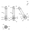
- FIGS. 1a to 1d is shown in four different views, an inventive vortex shown without the fastening device for fixing the end of a string of the musical instrument also belonging clamping element.
- the vortex 1 is an elongated part, technically a wave. At its one longitudinal end, it has a connecting portion 2 for connection to an actuating mechanism, for example a hand-wheel drive for rotational adjustment of the vortex 1.
- the vertebra 1 further has a winding section 3, on which a string of the musical instrument wound or from which they are unwound can be used to increase or decrease the tension of the strings to adjust the tuning of the string.
- a winding section 3 On the opposite side of the connecting portion 2 of the winding section 3 is limited by a circumferential collar 4, on the one hand forms a lateral stop for the string and thus a limitation of the winding section 3, but on the other hand also on the winding section 3 opposite side forms an abutment surface 5, whose function will be explained below.
- On the side opposite the winding section 3 side of the collar 4 further includes a holding portion 6, which forms the connecting portion 2 opposite free end of the vortex 1.
- the holding portion 6 has a not-shown here external thread, which cooperates in a manner to be described later with the internal thread of a clamping element.
- incisions 7 are also provided at radially opposite positions, in which the collar 4 is cut to the diameter of the winding section. These cuts 7 are used to carry out a string or a string end of the winding section 3 on the opposite side of the collar 4 to the abutment surface. 5
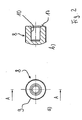
- Fig. 2 is shown as a clamping element, a clamping screw 8.
- This clamping screw is formed substantially cylindrical and has on its peripheral surface, which forms the grip portion of the clamping screw 8, a knurling 9.
- This knurling 9 improves the grip and allows easy operation of the clamping screw 8 with two fingers of one hand.
- the clamping screw 8 on its inside a there not graphically illustrated, but provided with the reference numeral 10 internal thread.
- This internal thread is formed corresponding to the formed on the holding portion 6 of the vertebra 1 external thread and can be brought into engagement with this for screwing the clamping screw 8 on the free end of the vertebra 1 with the holding portion 6.
- the clamping screw 8 in axial Direction of the vortex 1 are screwed up and down, in particular with a clamping surface 17 against the abutment surface 5 are pressed.
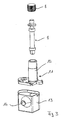
- FIG. 3 an assembly of the vortex 1 with the clamping screw 8 is shown in an exploded view, and further a drive housing, in which the vortex 1 is used.
- the drive housing consists of a guide member 11 with molded thereon housing cover and a housing part 13 in which the drive units are arranged.
- the guide member 11 is provided with a guide sleeve 12 in which the swivel 1 is rotatably mounted.
- an opening 14 is arranged through which a drive axle, for example with a hand screw for manual adjustment of the rotational angular position of the vortex 1 can be passed.
- the structure shown here is set up in particular for a motor drive of the vortex 1, for which a motor, possibly with a gear unit, can be arranged in the housing part 13.
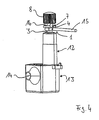
- Fig. 4 is finally the assembly of in Fig. 3 shown in exploded view parts, and it is shown how a string 1 5 runs onto the winding portion 3 and is fixed with a free end 16 in accordance with the invention by means of the fastening device.
- the string 15 runs, as already mentioned, on the winding section 3, its free end is passed through the incision 7 in the collar 4 and placed in a circle around almost 360 ° on the abutment surface of the collar 4.
- the clamping screw 8 is screwed onto the holding portion of the vertebra 1 and presses with its clamping surface on the free end 16 of the string 15 and thus jammed this free end 16 against the abutment surface of the collar. 4
- the free end 16 of the string 15 can be set as easy and fast on the vortex 1.
- the clamping takes place over a considerable longitudinal portion of the free end 16 of the string 15, so that the forces distributed over a longer range of the string 15 are applied to this and not, as known in the art, selectively. This reduces clearly the risk of cracking or breaking the string.
Description
Die vorliegende Erfindung betrifft einen Wirbel für ein Saiteninstrument mit den Merkmalen des Oberbegriffs des Anspruchs 1. Sie betrifft ferner ein mit einem solchen Wirbel versehenes Saiteninstrument selbst.The present invention relates to a vortex for a stringed instrument having the features of the preamble of
Als Wirbel werden bei Saiteninstrumenten die drehbaren Holzpflöcke oder Metallstifte, auf denen die Saitenenden aufgerollt werden, bezeichnet. Mit ihrer Hilfe kann die Spannung der Saiten verändert und das Instrument damit gestimmt werden. Zum Beispiel bei Gitarren oder Violinen sind diese Wirbel am sogenannten Kopf angeordnet, bei modernen Gitarren sind die Wirbel mittels entsprechender Handhabung über Getriebestufen verstellbar, um auch eine Feinstimmung bewirken zu können.In the case of stringed instruments, the whirling wooden pegs or metal pegs on which the string ends are rolled up are called vertebrae. With their help, the tension of the strings can be changed and the instrument can be tuned with it. For example, in guitars or violins, these vortices are arranged on the so-called head, in modern guitars, the vertebrae are adjustable by means of appropriate handling gear stages, to be able to cause a fine tuning.
Wirbel sind mithin im technischen Sinne Wellen, auf die ein Saitenende zur Straffung und damit höheren Stimmung aufgewickelt bzw. zum Entspannen und damit tieferen Stimmen von dieser abgewickelt werden kann.In the technical sense, therefore, whirls are waves on which a string end can be wound up for a tightening and thus higher mood, or for relaxing and thus for deeper voices.
Zum Festlegen einer Saite an einem Wirbel weist dieser typischerweise in einem Wickelabschnitt eine durchgehende Bohrung oder einen Schlitz auf, durch die bzw. durch den das Saitenende hindurchgeführt und anschließend durch Knoten bzw. Verschlingen festgelegt wird. Diese Art der Festlegung eines Saitenendes an dem Wirbel ist kompliziert auszuführen und es besteht - insbesondere bei nicht fachgerechter Ausführung - die Gefahr eines Lösens bzw. Nachgebens des Saitenendes und damit einhergehend einer Verstimmung des Instrumentes. Zudem nimmt ein zum Festlegen des Saitenendes hier angebrachter Knoten oder ein vergleichbares verwundenes Konstrukt einen erheblichen Raum ein, so dass der Platzbedarf für Wirbel vergleichsweise groß ist.For fixing a string to a vertebra, the latter typically has, in a winding section, a through hole or slot through which the string end is guided and subsequently fixed by knotting or entangling. This type of fixing a string end to the vortex is complicated to perform and there is - especially in non-professional execution - the risk of loosening or yielding of the end of the string and, consequently, a detuning of the instrument. In addition, a node attached here for fixing the end of the string or a similar twisted construct occupies a considerable space, so that the space required for vertebrae is comparatively large.
Die oben genannten Nachteile wirken sich insbesondere auch bei solchen Wirbeln aus, die als Bestandteil automatisierter Stimmsysteme motorisch angetrieben die Saitenspannung verstellen. Insbesondere hier kommt es auf eine hohe Festigkeit des festgelegten Saitenendes für eine reproduzierbare Stimmung des Instrumentes an. Auch ist für eine motorisch angetriebene Verstellung ein möglichst gleichmäßig erfolgendes Aufwickeln des Saitenendes auf den Wirbel von Vorteil, was bei einem einseitig an einen Wirbel angeordneten Knoten oder einer ähnlichen Schlinge nur schwer möglich ist, da dort die Saite stets über die durch den Knoten oder die Schlinge gebildete Erhöhung aufläuft.The above-mentioned disadvantages also have an effect, in particular, on such vertebrae which, as part of automated tuning systems, adjust the tension of the strings by motor-driven means. In particular, it depends on a high strength of the specified end of the string for a reproducible tuning of the instrument. Also, for a motor-driven adjustment as uniform as possible winding the string end on the vertebrae of advantage, which is difficult for a one-sided arranged on a vertebra node or a similar loop, since there the string always on the through the node or the Loop formed increase accumulates.
Es hat im Stand der Technik ferner Versuche gegeben, die Saitenenden durch punktuelles Verklemmen an einen Wirbel festzulegen, indem z.B. ein Klemmdorn auf einen Punkt der Saite geführt und die Saite zwischen dem Klemmdorn und einem Widerlager eingespannt wird. Ein solches Beispiel ist in der
Ferner ist aus der
Hier soll nun mit der vorliegenden Erfindung Abhilfe geschaffen und eine Möglichkeit der Festlegung eines Saitenendes an einem Wirbel bzw. ein solcher Wirbel selbst angegeben werden, der einerseits eine feste und verrutschsichere Festlegung des Saitenendes mit geringem Aufwand erlaubt und dabei eine übermäßig hohe Beanspruchung des Saitenendes und damit die Gefahr eines Saitenbruches oder -risses gegenüber dem Stand der Technik erheblich vermindert.Here is to be remedied with the present invention and given a way of defining a string end to a vertebra or such a vortex itself, on the one hand a firm and secure against slipping down the string end with little effort and thereby excessive stress on the string end and so that the risk of a string break or crack compared to the prior art significantly reduced.
Diese Aufgabe wird gelöst durch einen Wirbel für ein Saiteninstrument mit den Merkmalen des Patentanspruches 1. Vorteilhafte Weiterbildungen eines solchen erfindungsgemäßen Wirbels sind in den Unteransprüchen 2 bis 5 angegeben. Mit der Erfindung wird ferner ein vorteilhaft weitergebildetes Saiteninstrument bereitgestellt, welches einen neuartigen Wirbel aufweist.This object is achieved by a vortex for a stringed instrument having the features of
Ein Wirbel für ein Saiteninstrument, der in erfindungsgemäßer Weise insbesondere für eine Gitarre, aber auch für andere Saiteninstrumente Verwendung finden kann, verfügt über einen Wickelabschnitt, auf dem die Saite aufläuft, sowie über eine Befestigungseinrichtung zum Festlegen eines freien Endes der Saite. In erfindungsgemäßer Weise umfasst die Befestigungseinrichtung ein Klemmelement, einen Widerlagerabschnitt an dem Wirbel und einen Halteabschnitt an dem Wirbel. Dabei sind der Halteabschnitt und das Klemmelement derart eingerichtet, dass das Klemmelement entlang des Halteabschnittes axial auf den Wirbel verschoben und in einer Klemmposition arretiert werden kann. Ferner sind Klemmelement und Widerlagerabschnitt so eingerichtet, dass sie zwischen sich einen Längsabschnitt des freien Endes der Saite einklemmen und halten können. Unter einem Längsabschnitt des freien Endes der Saite ist dabei ein lang erstreckter Abschnitt zu verstehen, der eine deutliche Längenerstreckung aufweist und sich insoweit von einem nur punktuell einzuklemmenden Stück der Saite unterscheidet.A vortex for a stringed instrument, which can be used according to the invention in particular for a guitar, but also for other stringed instruments, has a winding section on which the string runs, and a fastening device for fixing a free end of the string. In accordance with the invention, the fastening device comprises a clamping element, an abutment section on the vortex and a holding section on the vortex. In this case, the holding section and the clamping element are set up such that the clamping element can be axially displaced along the holding section onto the vortex and locked in a clamping position. Further, the clamping member and the abutment portion are arranged to interpose one another Clamp longitudinal section of the free end of the string and can hold. A longitudinal section of the free end of the string is to be understood as an elongate section which has a clear longitudinal extent and differs in this respect from a piece of the string to be clamped only at certain points.
Mit einem solchen in erfindungsgemäßer Weise ausgestalteten Wirbel kann das Ende einer dort festzulegenden und mit dem Wirbel hinsichtlich ihrer Spannung und Stimmung einzustellenden Saite nicht nur einfach befestigt werden, indem ein entsprechender Längsabschnitt des freien Endes der Saite auf dem Widerlagerabschnitt angeordnet und mittels des entlang des Halteabschnittes auf dem Wirbel verschobenen Klemmelementes dort verklemmt wird. Das Verklemmen des Saitenendes kann dabei insbesondere auch in hohem Maße positionsgetreu und stabil erfolgen, so dass nicht etwa wie bei der traditionellen Methode ein Nachgeben eines Knotens oder ein Lösen aus der Befestigung zu befürchten stehen und damit auch keine dadurch hervorgerufene Verstimmung der dort festgelegten Saite. Dadurch, dass die Saite entlang eines Längsabschnittes, also über einen deutlich von einer punktuellen Klemmung abweichenden Abschnitt ihrer Länge zwischen dem Widerlagerabschnitt und dem Klemmelement eingeklemmt wird, verteilen sich die aufgebrachten Klemmkräfte über einen weiteren Bereich der Saite, so dass es nicht zu Belastungsspitzen und der damit verbundenen Gefahr eines Brechens bzw. Reißens der Saite kommt.With such a vortex configured in accordance with the invention, the end of a string to be defined therein and to be adjusted with respect to its tension and tuning can not simply be fixed by arranging a corresponding longitudinal section of the free end of the string on the abutment section and by means of the holding section clamped on the vertebra clamping element is clamped there. The jamming of the string end can be carried out in a particularly high positional and stable, so that not as in the traditional method a yielding of a node or a release from the attachment to be feared and thus no induced thereby detuning the specified there string. Due to the fact that the string is clamped along a longitudinal section, that is to say over a section of its length deviating significantly from a punctiform clamping between the abutment section and the clamping element, the applied clamping forces are distributed over a further region of the string, so that it is not too stressful and associated danger of breakage or tearing of the string comes.
Als Widerlagerabschnitt ist erfindungsgemäß ein umlaufender Kragen vorgesehen. Dieser umlaufende Kragen erstreckt sich um die Achse des Wirbels herum und dient als Auflage für einen Abschnitt des Saitenendes, der dort über einen erheblichen Umfangsteil (bis zu nahezu 360°) um die Achse des Wirbels herumgeführt und dann mit diesem gesamten Längenabschnitt mittels des Klemmelementes verklemmt werden kann. Ein solcher umlaufender Kragen bietet also bei kompaktem Bauraum die Möglichkeit, das Saitenende über eine erhebliche Längserstreckung zu klemmen und so die Klemmkräfte über einen weiten Abschnitt der Saite zu verteilen. Dies führt neben der bereits erwähnten Reduzierung von Spitzenentlasten auch zu einem verbesserten Halt, da über einen längeren und größeren Abschnitt des Saitenendes die Klemmung und damit der Rückhalt aufgrund der Klemm- und Reibungskräfte erfolgt.As an abutment portion, a circumferential collar is provided according to the invention. This circumferential collar extends around the axis of the vortex and serves as a support for a portion of the string end, which there guided around a considerable peripheral part (up to almost 360 °) about the axis of the vortex and then clamped with this entire length portion by means of the clamping element can be. Such a circumferential collar thus offers the possibility in compact space to clamp the string end over a considerable longitudinal extent and thus to distribute the clamping forces over a wide portion of the string. This results in addition to the already mentioned reduction of Spitzenentlasten also improved support, as over a longer and larger portion of the string end the clamping and thus the backing due to the clamping and frictional forces takes place.
Der umlaufende Kragen des erfindungsgemäßen Wirbels ist ferner entlang des Umfanges um den Wirbel teilweise unterbrochen ist, weist einen oder mehrere Einschnitte auf genannt ist. Ein solcher Einschnitt kann z.B. genutzt werden, um das Ende der Saite von einer Seite des Kragens, auf der z.B. der Wickelabschnitt liegen kann (vgl. Anspruch 2) zu der gegenüberliegenden Seite, auf der der Kragen die Widerlagerfläche aufweist und auf der z.B. der Halteabschnitt liegen kann (vgl. Anspruch 2), zu führen, ohne hier einen besonders scharfkantigen Knick der Saite über den Kragenrand formen zu müssen. Bei einer solchen Führung des Saitenendes von einer Kragenseite durch einen Einschnitt als Durchführung hindurch hin zum Wickelabschnitt kann das Saitenende in vergleichsweise sanft gekrümmten Radien geführt werden, was wiederum der Haltbarkeit der Saite zugute kommt, bei der scharfwinkelige Umlenkungen stets einen Schwächungspunkt darstellen, insbesondere dann, wenn es dort noch zu Reibung aufgrund der schwingenden Saite kommt.The circumferential collar of the vortex according to the invention is further partially along the circumference around the vertebra is interrupted, has one or more cuts on is called. Such a cut can e.g. can be used to measure the end of the string from one side of the collar, on e.g. the winding section may (see claim 2) to the opposite side, on which the collar has the abutment surface and on the e.g. The holding section can lie (see claim 2) to lead, without having to form here a particularly sharp-edged kink of the string on the collar edge. In such a guide of the string end from a collar side through an incision as a passage through to the winding section, the string end can be performed in comparatively gently curved radii, which in turn benefits the durability of the string, in which sharp-angled deflections always represent a point of weakness, especially then if there is still friction due to the vibrating string.
Gemäß einer weiteren vorteilhaften Ausgestaltung der Erfindung kann der Halteabschnitt ein mit einem Außengewinde versehener Abschnitt des Wirbels und das Klemmelement ein Schraubelement mit einem zu dem Außengewinde korrespondierenden Innengewinde sein. Eine derartige Lösung ergibt eine besonders einfache Handhabung, zudem kann durch passende Wahl der Gewindesteigung und der sonstigen Gestaltung von Außen- und Innengewinde eine sichere Verriegelung zwischen dem Außengewinde und dem Innengewinde in der Position erreicht werden, in der das Klemmelement gegen die an dem Widerlager anstoßende Saite drückt und diese aufgrund der ausgeübten Klemmkraft hält.According to a further advantageous embodiment of the invention, the holding portion may be a provided with an external thread portion of the vortex and the clamping element is a screw with a corresponding to the external thread internal thread. Such a solution results in a particularly simple handling, also can be achieved by appropriate choice of the thread pitch and the other design of male and female thread a secure locking between the external thread and the internal thread in the position in which the clamping element abutting against the abutment Presses string and holds them due to the applied clamping force.
Von besonderem Vorteil ist dabei, wenn der mit dem Außengewinde versehene Abschnitt an einem freien Ende des Wirbels in einer solchen Weise angeordnet ist, dass das Schraubelement vollständig von dem Wirbel lösbar auf den mit dem Außengewinde versehenen Halteabschnitt aufschraubbar ist. Diese Art der Gestaltung ermöglicht insbesondere einen einfachen Austausch und eine Pflege der Teile. Selbstverständlich ist es auch möglich, das Schraubelement so zu bilden, dass es nicht, jedenfalls nicht ohne weiteres von dem mit dem Außengewinde versehenen Abschnitt des Wirbels lösbar ist, um z.B. einen Verlust des schraubbaren Klemmelementes bei versehentlichem Überöffnen desselben zu vermeiden.It is particularly advantageous if the externally threaded portion is arranged at a free end of the vortex in such a manner that the screw is completely detachable from the vortex screwed onto the externally threaded holding portion. This type of design allows in particular easy replacement and care of the parts. Of course, it is also possible to form the screw element so that it is not, at least not readily solvable from the externally threaded portion of the vortex, for example, to avoid the loss of the screwable clamping element in case of accidental over-opening of the same.
Das Schraubelement ist für eine bessere Handhabung desselben in vorteilhafter Weise mit einem Griffabschnitt versehen, der insbesondere gezahnt, gerändelt oder in sonstiger Weise strukturiert als Umfangsabschnitt ausgebildet sein kann. Mit solchen Rändelschrauben oder in anderer Weise mit Griffstrukturen versehenen Schraubelementen ist eine Handhabung ohne Werkzeug besonders einfach möglich.The screw is provided for better handling of the same in an advantageous manner with a handle portion, which may in particular be toothed, knurled or structured in any other way as a peripheral portion. With such thumbscrews or provided in other ways with handle structures screw elements handling without tools is particularly easy.
Weitere Vorteile und Merkmale der Erfindung ergeben sich aus der nachfolgenden Beschreibung eines Ausführungsbeispiels anhand der beigefügten Figuren. Dabei zeigen:
- Fig. 1 a bis d
- einen erfindungsgemäßen Wirbel in einem ersten Ausführungsbeispiel in vier verschiedenen Ansichten, in
Fig. 1 a in einer Seitenansicht, inFig. 1b in einer Ansicht von der inFig. 1 a rechts dargestellten Stirnseite her, inFig. 1c in einer weiteren Seitenansicht, gegenüber der Seitenansicht gemäßFig. 1 a um 90° um die Längsachse des Wirbels gedreht, und inFig. 1d in einer dreidimensionalen Darstellung; - Fig. 2a
- und b in zwei verschiedenen Ansichten eine Klemmschraube zum Zusammenwirken mit dem Wirbel gemäß
Fig. 1 zum Bilden der Einrichtung zum Festlegen des zweiten Endes; - Fig. 3
- in einer Explosionsdarstellung den Wirbel gemäß
Fig. 1 mit der Klemmschraube gemäßFig. 2 und zwei für dieses Ausführungsbeispiel mit vorgesehenen Gehäuseteilen; - Fig. 4
- die in
Fig. 3 in Explosionsdarstellung gezeigte Einheit in zusammengebauter Form mit einem auf dem Wirbel auflaufenden und in der erfindungsgemäßen Klemmeinrichtung festgelegten Saitenende.
- Fig. 1 a to d
- a vortex according to the invention in a first embodiment in four different views, in
Fig. 1 a in a side view, inFig. 1b in a view of the inFig. 1 a front side shown on the right, inFig. 1c in a further side view, opposite the side view according toFig. 1 a rotated 90 ° about the longitudinal axis of the vortex, and inFig. 1d in a three-dimensional representation; - Fig. 2a
- and b in two different views a clamping screw for cooperation with the vortex according to
Fig. 1 for forming the means for setting the second end; - Fig. 3
- in an exploded view of the vortex according to
Fig. 1 with the clamping screw according toFig. 2 and two for this embodiment with provided housing parts; - Fig. 4
- in the
Fig. 3 in an exploded view unit in assembled form with a auflaufenden on the vortex and fixed in the clamping device according to the invention string end.
In den Figuren ist ein Ausführungsbeispiel eines erfindungsgemäßen Wirbels gezeigt, der hier ein Wirbel für eine Gitarre, insbesondere eine E-Gitarre ist. Die gezeigten Figuren sind dabei rein schematisch und stellen keine vollständigen Konstruktionszeichnungen dar. Sie dienen lediglich der Erläuterung und Beschreibung eines Ausführungsbeispiels zur weiteren Veranschaulichung der Erfindung.In the figures, an embodiment of a vortex according to the invention is shown, which is here a vortex for a guitar, in particular an electric guitar. The figures shown are purely schematic and do not represent complete design drawings. They are merely illustrative and description of an embodiment for further illustrating the invention.
In den
Der Wirbel 1 verfügt ferner über einen Wickelabschnitt 3, auf welchem eine Saite des Musikinstrumentes aufgewickelt bzw. von welchem diese abgewickelt werden kann, um die Saitenspannung zu erhöhen oder zu erniedrigen und so die Stimmung der Saite einzustellen. Auf der dem Verbindungsabschnitt 2 gegenüberliegenden Seite ist der Wickelabschnitt 3 begrenzt durch einen umlaufenden Kragen 4, der einerseits einen seitlichen Anschlag für die Saite und damit eine Begrenzung des Wickelabschnittes 3 bildet, andererseits aber auch auf der dem Wickelabschnitt 3 gegenüberliegenden Seite eine Widerlagerfläche 5 ausbildet, deren Funktion nachstehend noch erläutert wird. Auf der dem Wickelabschnitt 3 gegenüberliegenden Seite des Kragens 4 schließt sich ferner ein Halteabschnitt 6 an, der das dem Verbindungsabschnitt 2 gegenüberliegende freie Ende des Wirbels 1 bildet. Der Halteabschnitt 6 weist ein hier nicht näher dargestelltes Außengewinde auf, welches in später noch zu beschreibender Weise mit dem Innengewinde eines Klemmelementes zusammenwirkt.The
In dem Kragen 4 sind ferner an radial einander gegenüberliegenden Positionen Einschnitte 7 vorgesehen, in denen der Kragen 4 bis auf den Durchmesser des Wickelabschnittes ausgeschnitten ist. Diese Einschnitte 7 dienen der Durchführung einer Saite bzw. eines Saitenendes vom Wickelabschnitt 3 auf die diesem gegenüberliegenden Seite des Kragens 4 zu der Widerlagerfläche 5.In the
In
Wie insbesondere in
In
Der hier gezeigte Aufbau ist insbesondere auch für einen motorischen Antrieb des Wirbels 1 eingerichtet, wofür in dem Gehäuseteil 13 ein Motor, ggf. mit einer Getriebeeinheit, angeordnet werden kann.The structure shown here is set up in particular for a motor drive of the
In
Das freie Ende 16 der Saite 15 kann so handwerklich einfach und schnell an dem Wirbel 1 festgelegt werden. So ist es lediglich erforderlich, das freie Ende 16 auf der Widerlagerfläche 5 des Kragens 4 anzuordnen und die Klemmschraube 8 in Richtung des Kragens 4 und seiner Widerlagerfläche 5 zu schrauben und so das freie Ende 16 der Saite 15 zwischen der Widerlagerfläche 5 und der Klemmfläche 17 einzuklemmen. Wie aus
- 11
- Wirbelwhirl
- 22
- Verbindungsabschnittconnecting portion
- 33
- Wickelabschnittwinding section
- 44
- Kragencollar
- 55
- WiderlagerflächeAbutment surface
- 66
- Halteabschnittholding section
- 77
- Einschnittincision
- 88th
- Klemmschraubeclamping screw
- 99
- Rändelungknurling
- 1010
- Innengewindeinner thread
- 1111
- Führungsteilguide part
- 1212
- Führungshülseguide sleeve
- 1313
- Gehäuseteilhousing part
- 1414
- Öffnungopening
- 1515
- Saitestring
- 1616
- freies Endefree end
- 1717
- Klemmflächeclamping surface
Claims (6)
- Machine head for a stringed instrument, especially a guitar, with a winding section (3), on which a string (15) can be wound and a securing device for fastening a free end (16) of the string (15), where the securing device consists of the following elements:i) A clamping element (8),ii) a thrust collar section (4, 5) on the machine head (1) andiii) a holding section (6) on the machine head (1),where the holding section (6) and the clamping element (8) are so set up that the clamping element (8) is shifted axially along the holding section (6) relative to the machine head (1) and can be locked in a clamped position, and where the clamping element (8) and the thrust collar section (4, 5) are so set up that they can clamp and hold a length of the free end (16) of the string (15) between them and characterised by a circumferential collar (4) as thrust resisting section with a least one notch (7) in the collar (4) for the threading through of the free end (16) of the string (15).
- Machine head according to Claim 1, characterised in that, when seen in the axial direction of the machine head (1), the winding section (3) being located on one side of the collar (4) and the holding section (6) on the opposite side of the collar (4), especially when the holding section (6) is close to the collar (6).
- Machine head according to one of the previous claims, characterised in that the holding section (6) of the machine head (1) having an external thread and the clamping element (8) being a threaded element with an internal thread (10) that matches the external thread of section (6).
- Machine head according to Claim 3, characterised in that the section with the external thread being so positioned on the free end of the machine head (1) that the threaded element with internal thread can be completely detached from the external thread section of machine head (1).
- Machine head according to one of the Claims 3 or 4, characterised in that the threaded element having a section (9) that can be gripped, especially a toothed, knurled or in other manner structured circumferential section.
- String instrument with at least one machine head according to one of the Claims 1 to 5.
Priority Applications (7)
| Application Number | Priority Date | Filing Date | Title |
|---|---|---|---|
| EP10157648.6A EP2369580B1 (en) | 2010-03-24 | 2010-03-24 | Pin for a stringed instrument |
| US13/636,788 US8710339B2 (en) | 2010-03-24 | 2011-03-24 | Tuning peg for a stringed instrument |
| CN201180015264.9A CN103026403B (en) | 2010-03-24 | 2011-03-24 | Tuning peg for a stringed instrument |
| PCT/EP2011/054570 WO2011117367A1 (en) | 2010-03-24 | 2011-03-24 | Tuning peg for a stringed instrument |
| KR1020127026754A KR20130054251A (en) | 2010-03-24 | 2011-03-24 | Tuning peg for a stringed instrument |
| CA2794224A CA2794224A1 (en) | 2010-03-24 | 2011-03-24 | Tuning peg for a stringed instrument |
| JP2013500516A JP2013522685A (en) | 2010-03-24 | 2011-03-24 | String spools |
Applications Claiming Priority (1)
| Application Number | Priority Date | Filing Date | Title |
|---|---|---|---|
| EP10157648.6A EP2369580B1 (en) | 2010-03-24 | 2010-03-24 | Pin for a stringed instrument |
Publications (2)
| Publication Number | Publication Date |
|---|---|
| EP2369580A1 EP2369580A1 (en) | 2011-09-28 |
| EP2369580B1 true EP2369580B1 (en) | 2014-04-02 |
Family
ID=42797421
Family Applications (1)
| Application Number | Title | Priority Date | Filing Date |
|---|---|---|---|
| EP10157648.6A Not-in-force EP2369580B1 (en) | 2010-03-24 | 2010-03-24 | Pin for a stringed instrument |
Country Status (7)
| Country | Link |
|---|---|
| US (1) | US8710339B2 (en) |
| EP (1) | EP2369580B1 (en) |
| JP (1) | JP2013522685A (en) |
| KR (1) | KR20130054251A (en) |
| CN (1) | CN103026403B (en) |
| CA (1) | CA2794224A1 (en) |
| WO (1) | WO2011117367A1 (en) |
Families Citing this family (5)
| Publication number | Priority date | Publication date | Assignee | Title |
|---|---|---|---|---|
| AU2015100011B4 (en) * | 2014-01-13 | 2015-07-16 | Apple Inc. | Temperature compensating transparent force sensor |
| CN106463102A (en) | 2014-03-12 | 2017-02-22 | 希欧多尔·巴克斯霍顿·柯伦 | Device for replacing musical instrument strings |
| JP2016081020A (en) * | 2014-10-09 | 2016-05-16 | 満 倉知 | Tuning peg (bobbin) for guitar with removable tuning peg knob |
| KR101762387B1 (en) * | 2015-07-24 | 2017-07-28 | 주식회사 하이딥 | Touch pressure sensitivity compensation method and computer readable recording medium |
| TWM556912U (en) * | 2017-06-05 | 2018-03-11 | 子恩 譚 | Tune holder for string instruments |
Family Cites Families (7)
| Publication number | Priority date | Publication date | Assignee | Title |
|---|---|---|---|---|
| US532053A (en) * | 1895-01-08 | String-clamp for musical instruments | ||
| US4748889A (en) * | 1987-04-07 | 1988-06-07 | Schaller Rene K F | Machine head |
| US5103708A (en) * | 1991-01-16 | 1992-04-14 | Steinberger Sound Corporation | Gearless tuner |
| DE60121622T2 (en) * | 2001-01-12 | 2007-07-26 | Gotoh Gut Co., Ltd., Isesaki | SAITENWICKLER FOR STRING INSTRUMENTS AND METHOD FOR THE PRODUCTION OF CHORD WICKER |
| US6580022B2 (en) * | 2001-04-12 | 2003-06-17 | Han-Soo Kang | Machine head for guitar |
| DE102005014625A1 (en) * | 2005-03-23 | 2006-10-05 | Rudolf Wittner Gmbh & Co. Kg | Rotary tuning component for stringed musical instrument e.g. violin, has rotation core area that has string holding areas arranged in different distances with respect to rotary axis provided inside tuning box of stringed musical instrument |
| CN201170946Y (en) * | 2008-02-26 | 2008-12-24 | 宾玮兴业股份有限公司 | Structure for adjusting tight degree of strings |
-
2010
- 2010-03-24 EP EP10157648.6A patent/EP2369580B1/en not_active Not-in-force
-
2011
- 2011-03-24 KR KR1020127026754A patent/KR20130054251A/en not_active Application Discontinuation
- 2011-03-24 CA CA2794224A patent/CA2794224A1/en not_active Abandoned
- 2011-03-24 JP JP2013500516A patent/JP2013522685A/en not_active Ceased
- 2011-03-24 US US13/636,788 patent/US8710339B2/en not_active Expired - Fee Related
- 2011-03-24 CN CN201180015264.9A patent/CN103026403B/en not_active Expired - Fee Related
- 2011-03-24 WO PCT/EP2011/054570 patent/WO2011117367A1/en active Application Filing
Also Published As
| Publication number | Publication date |
|---|---|
| CN103026403A (en) | 2013-04-03 |
| US8710339B2 (en) | 2014-04-29 |
| KR20130054251A (en) | 2013-05-24 |
| CA2794224A1 (en) | 2011-09-29 |
| CN103026403B (en) | 2015-06-03 |
| US20130008297A1 (en) | 2013-01-10 |
| JP2013522685A (en) | 2013-06-13 |
| WO2011117367A1 (en) | 2011-09-29 |
| EP2369580A1 (en) | 2011-09-28 |
Similar Documents
| Publication | Publication Date | Title |
|---|---|---|
| DE3212828C2 (en) | Surgical clip and surgical clip removal device | |
| EP0391384B1 (en) | Lithotriptor | |
| EP2369580B1 (en) | Pin for a stringed instrument | |
| EP0868128B1 (en) | Handle for a stick | |
| DE3344864A1 (en) | CONNECTING DEVICE FOR OPTICAL FIBERS | |
| WO2018184708A1 (en) | Adjustable fiber collimator | |
| DE3804749C2 (en) | ||
| EP0440682B1 (en) | Process and device for stringing rackets for ball games | |
| DE3522728C2 (en) | ||
| DE102005056252B4 (en) | Peg for a stringed instrument | |
| EP2730232A1 (en) | Suture tensioning device | |
| DE4200858A1 (en) | DEVICE FOR TUNING THE STRINGS OF A MUSICAL INSTRUMENT | |
| EP0273372B1 (en) | Trussrod for string instruments | |
| DE1961980B2 (en) | Hub attachment | |
| DE2933845C2 (en) | ||
| DE102006057954B4 (en) | Dental floss holder | |
| EP2944267B1 (en) | Surgical suturing device | |
| DE3490386C2 (en) | ||
| DE3914591C2 (en) | ||
| DE4408696C1 (en) | Fixture and tuning mechanism for string of plucked musical instrument | |
| DE3808238A1 (en) | Screwdriver with torque limiting device - has hollow handle accommodating shaft surrounded by friction-locking spiral spring with one end fixed to handle | |
| DE102011117991B3 (en) | Snare rug for snare drum to play orchestra or marching music, has enveloping body whose outer dimensions are varied such that dimensions along partial section conically increase and decrease from end of rug in direction of other end of rug | |
| EP1993352A1 (en) | Holder for roll units, receiving module for a roll holder, and fishing rod comprising one such holder or receiving module | |
| DE19858452A1 (en) | Reel for cutter on harvesters has tines held in longitudinal grooves on tube and locked by clamping members | |
| DE102005014625A1 (en) | Rotary tuning component for stringed musical instrument e.g. violin, has rotation core area that has string holding areas arranged in different distances with respect to rotary axis provided inside tuning box of stringed musical instrument |
Legal Events
| Date | Code | Title | Description |
|---|---|---|---|
| PUAI | Public reference made under article 153(3) epc to a published international application that has entered the european phase |
Free format text: ORIGINAL CODE: 0009012 |
|
| AK | Designated contracting states |
Kind code of ref document: A1 Designated state(s): AT BE BG CH CY CZ DE DK EE ES FI FR GB GR HR HU IE IS IT LI LT LU LV MC MK MT NL NO PL PT RO SE SI SK SM TR |
|
| AX | Request for extension of the european patent |
Extension state: AL BA ME RS |
|
| 17P | Request for examination filed |
Effective date: 20120328 |
|
| GRAP | Despatch of communication of intention to grant a patent |
Free format text: ORIGINAL CODE: EPIDOSNIGR1 |
|
| INTG | Intention to grant announced |
Effective date: 20131011 |
|
| GRAS | Grant fee paid |
Free format text: ORIGINAL CODE: EPIDOSNIGR3 |
|
| GRAA | (expected) grant |
Free format text: ORIGINAL CODE: 0009210 |
|
| AK | Designated contracting states |
Kind code of ref document: B1 Designated state(s): AT BE BG CH CY CZ DE DK EE ES FI FR GB GR HR HU IE IS IT LI LT LU LV MC MK MT NL NO PL PT RO SE SI SK SM TR |
|
| REG | Reference to a national code |
Ref country code: GB Ref legal event code: FG4D Free format text: NOT ENGLISH |
|
| REG | Reference to a national code |
Ref country code: AT Ref legal event code: REF Ref document number: 660532 Country of ref document: AT Kind code of ref document: T Effective date: 20140415 Ref country code: CH Ref legal event code: EP |
|
| REG | Reference to a national code |
Ref country code: IE Ref legal event code: FG4D Free format text: LANGUAGE OF EP DOCUMENT: GERMAN |
|
| REG | Reference to a national code |
Ref country code: DE Ref legal event code: R096 Ref document number: 502010006521 Country of ref document: DE Effective date: 20140522 |
|
| REG | Reference to a national code |
Ref country code: NL Ref legal event code: VDEP Effective date: 20140402 |
|
| REG | Reference to a national code |
Ref country code: LT Ref legal event code: MG4D |
|
| PG25 | Lapsed in a contracting state [announced via postgrant information from national office to epo] |
Ref country code: FI Free format text: LAPSE BECAUSE OF FAILURE TO SUBMIT A TRANSLATION OF THE DESCRIPTION OR TO PAY THE FEE WITHIN THE PRESCRIBED TIME-LIMIT Effective date: 20140402 Ref country code: CY Free format text: LAPSE BECAUSE OF FAILURE TO SUBMIT A TRANSLATION OF THE DESCRIPTION OR TO PAY THE FEE WITHIN THE PRESCRIBED TIME-LIMIT Effective date: 20140402 Ref country code: LT Free format text: LAPSE BECAUSE OF FAILURE TO SUBMIT A TRANSLATION OF THE DESCRIPTION OR TO PAY THE FEE WITHIN THE PRESCRIBED TIME-LIMIT Effective date: 20140402 Ref country code: NO Free format text: LAPSE BECAUSE OF FAILURE TO SUBMIT A TRANSLATION OF THE DESCRIPTION OR TO PAY THE FEE WITHIN THE PRESCRIBED TIME-LIMIT Effective date: 20140702 Ref country code: CZ Free format text: LAPSE BECAUSE OF FAILURE TO SUBMIT A TRANSLATION OF THE DESCRIPTION OR TO PAY THE FEE WITHIN THE PRESCRIBED TIME-LIMIT Effective date: 20140402 Ref country code: NL Free format text: LAPSE BECAUSE OF FAILURE TO SUBMIT A TRANSLATION OF THE DESCRIPTION OR TO PAY THE FEE WITHIN THE PRESCRIBED TIME-LIMIT Effective date: 20140402 Ref country code: BG Free format text: LAPSE BECAUSE OF FAILURE TO SUBMIT A TRANSLATION OF THE DESCRIPTION OR TO PAY THE FEE WITHIN THE PRESCRIBED TIME-LIMIT Effective date: 20140702 Ref country code: GR Free format text: LAPSE BECAUSE OF FAILURE TO SUBMIT A TRANSLATION OF THE DESCRIPTION OR TO PAY THE FEE WITHIN THE PRESCRIBED TIME-LIMIT Effective date: 20140703 Ref country code: IS Free format text: LAPSE BECAUSE OF FAILURE TO SUBMIT A TRANSLATION OF THE DESCRIPTION OR TO PAY THE FEE WITHIN THE PRESCRIBED TIME-LIMIT Effective date: 20140802 |
|
| PG25 | Lapsed in a contracting state [announced via postgrant information from national office to epo] |
Ref country code: PL Free format text: LAPSE BECAUSE OF FAILURE TO SUBMIT A TRANSLATION OF THE DESCRIPTION OR TO PAY THE FEE WITHIN THE PRESCRIBED TIME-LIMIT Effective date: 20140402 Ref country code: ES Free format text: LAPSE BECAUSE OF FAILURE TO SUBMIT A TRANSLATION OF THE DESCRIPTION OR TO PAY THE FEE WITHIN THE PRESCRIBED TIME-LIMIT Effective date: 20140402 Ref country code: HR Free format text: LAPSE BECAUSE OF FAILURE TO SUBMIT A TRANSLATION OF THE DESCRIPTION OR TO PAY THE FEE WITHIN THE PRESCRIBED TIME-LIMIT Effective date: 20140402 Ref country code: LV Free format text: LAPSE BECAUSE OF FAILURE TO SUBMIT A TRANSLATION OF THE DESCRIPTION OR TO PAY THE FEE WITHIN THE PRESCRIBED TIME-LIMIT Effective date: 20140402 Ref country code: SE Free format text: LAPSE BECAUSE OF FAILURE TO SUBMIT A TRANSLATION OF THE DESCRIPTION OR TO PAY THE FEE WITHIN THE PRESCRIBED TIME-LIMIT Effective date: 20140402 |
|
| PG25 | Lapsed in a contracting state [announced via postgrant information from national office to epo] |
Ref country code: PT Free format text: LAPSE BECAUSE OF FAILURE TO SUBMIT A TRANSLATION OF THE DESCRIPTION OR TO PAY THE FEE WITHIN THE PRESCRIBED TIME-LIMIT Effective date: 20140804 |
|
| REG | Reference to a national code |
Ref country code: DE Ref legal event code: R097 Ref document number: 502010006521 Country of ref document: DE |
|
| PG25 | Lapsed in a contracting state [announced via postgrant information from national office to epo] |
Ref country code: EE Free format text: LAPSE BECAUSE OF FAILURE TO SUBMIT A TRANSLATION OF THE DESCRIPTION OR TO PAY THE FEE WITHIN THE PRESCRIBED TIME-LIMIT Effective date: 20140402 Ref country code: RO Free format text: LAPSE BECAUSE OF FAILURE TO SUBMIT A TRANSLATION OF THE DESCRIPTION OR TO PAY THE FEE WITHIN THE PRESCRIBED TIME-LIMIT Effective date: 20140402 Ref country code: DK Free format text: LAPSE BECAUSE OF FAILURE TO SUBMIT A TRANSLATION OF THE DESCRIPTION OR TO PAY THE FEE WITHIN THE PRESCRIBED TIME-LIMIT Effective date: 20140402 Ref country code: SK Free format text: LAPSE BECAUSE OF FAILURE TO SUBMIT A TRANSLATION OF THE DESCRIPTION OR TO PAY THE FEE WITHIN THE PRESCRIBED TIME-LIMIT Effective date: 20140402 |
|
| PLBE | No opposition filed within time limit |
Free format text: ORIGINAL CODE: 0009261 |
|
| STAA | Information on the status of an ep patent application or granted ep patent |
Free format text: STATUS: NO OPPOSITION FILED WITHIN TIME LIMIT |
|
| 26N | No opposition filed |
Effective date: 20150106 |
|
| PG25 | Lapsed in a contracting state [announced via postgrant information from national office to epo] |
Ref country code: IT Free format text: LAPSE BECAUSE OF FAILURE TO SUBMIT A TRANSLATION OF THE DESCRIPTION OR TO PAY THE FEE WITHIN THE PRESCRIBED TIME-LIMIT Effective date: 20140402 |
|
| REG | Reference to a national code |
Ref country code: DE Ref legal event code: R097 Ref document number: 502010006521 Country of ref document: DE Effective date: 20150106 |
|
| PG25 | Lapsed in a contracting state [announced via postgrant information from national office to epo] |
Ref country code: SI Free format text: LAPSE BECAUSE OF FAILURE TO SUBMIT A TRANSLATION OF THE DESCRIPTION OR TO PAY THE FEE WITHIN THE PRESCRIBED TIME-LIMIT Effective date: 20140402 |
|
| PG25 | Lapsed in a contracting state [announced via postgrant information from national office to epo] |
Ref country code: MC Free format text: LAPSE BECAUSE OF FAILURE TO SUBMIT A TRANSLATION OF THE DESCRIPTION OR TO PAY THE FEE WITHIN THE PRESCRIBED TIME-LIMIT Effective date: 20140402 Ref country code: LU Free format text: LAPSE BECAUSE OF FAILURE TO SUBMIT A TRANSLATION OF THE DESCRIPTION OR TO PAY THE FEE WITHIN THE PRESCRIBED TIME-LIMIT Effective date: 20150324 |
|
| PGFP | Annual fee paid to national office [announced via postgrant information from national office to epo] |
Ref country code: DE Payment date: 20150922 Year of fee payment: 6 |
|
| REG | Reference to a national code |
Ref country code: CH Ref legal event code: PL |
|
| GBPC | Gb: european patent ceased through non-payment of renewal fee |
Effective date: 20150324 |
|
| REG | Reference to a national code |
Ref country code: FR Ref legal event code: ST Effective date: 20151130 |
|
| REG | Reference to a national code |
Ref country code: IE Ref legal event code: MM4A |
|
| PG25 | Lapsed in a contracting state [announced via postgrant information from national office to epo] |
Ref country code: GB Free format text: LAPSE BECAUSE OF NON-PAYMENT OF DUE FEES Effective date: 20150324 Ref country code: CH Free format text: LAPSE BECAUSE OF NON-PAYMENT OF DUE FEES Effective date: 20150331 Ref country code: LI Free format text: LAPSE BECAUSE OF NON-PAYMENT OF DUE FEES Effective date: 20150331 Ref country code: IE Free format text: LAPSE BECAUSE OF NON-PAYMENT OF DUE FEES Effective date: 20150324 |
|
| PG25 | Lapsed in a contracting state [announced via postgrant information from national office to epo] |
Ref country code: FR Free format text: LAPSE BECAUSE OF NON-PAYMENT OF DUE FEES Effective date: 20150331 |
|
| REG | Reference to a national code |
Ref country code: AT Ref legal event code: MM01 Ref document number: 660532 Country of ref document: AT Kind code of ref document: T Effective date: 20150324 |
|
| PG25 | Lapsed in a contracting state [announced via postgrant information from national office to epo] |
Ref country code: AT Free format text: LAPSE BECAUSE OF NON-PAYMENT OF DUE FEES Effective date: 20150324 |
|
| REG | Reference to a national code |
Ref country code: DE Ref legal event code: R119 Ref document number: 502010006521 Country of ref document: DE |
|
| PG25 | Lapsed in a contracting state [announced via postgrant information from national office to epo] |
Ref country code: MT Free format text: LAPSE BECAUSE OF FAILURE TO SUBMIT A TRANSLATION OF THE DESCRIPTION OR TO PAY THE FEE WITHIN THE PRESCRIBED TIME-LIMIT Effective date: 20140402 |
|
| PG25 | Lapsed in a contracting state [announced via postgrant information from national office to epo] |
Ref country code: DE Free format text: LAPSE BECAUSE OF NON-PAYMENT OF DUE FEES Effective date: 20161001 |
|
| PG25 | Lapsed in a contracting state [announced via postgrant information from national office to epo] |
Ref country code: HU Free format text: LAPSE BECAUSE OF FAILURE TO SUBMIT A TRANSLATION OF THE DESCRIPTION OR TO PAY THE FEE WITHIN THE PRESCRIBED TIME-LIMIT; INVALID AB INITIO Effective date: 20100324 Ref country code: SM Free format text: LAPSE BECAUSE OF FAILURE TO SUBMIT A TRANSLATION OF THE DESCRIPTION OR TO PAY THE FEE WITHIN THE PRESCRIBED TIME-LIMIT Effective date: 20140402 |
|
| PG25 | Lapsed in a contracting state [announced via postgrant information from national office to epo] |
Ref country code: BE Free format text: LAPSE BECAUSE OF NON-PAYMENT OF DUE FEES Effective date: 20150331 |
|
| PG25 | Lapsed in a contracting state [announced via postgrant information from national office to epo] |
Ref country code: TR Free format text: LAPSE BECAUSE OF FAILURE TO SUBMIT A TRANSLATION OF THE DESCRIPTION OR TO PAY THE FEE WITHIN THE PRESCRIBED TIME-LIMIT Effective date: 20140402 |
|
| PG25 | Lapsed in a contracting state [announced via postgrant information from national office to epo] |
Ref country code: MK Free format text: LAPSE BECAUSE OF FAILURE TO SUBMIT A TRANSLATION OF THE DESCRIPTION OR TO PAY THE FEE WITHIN THE PRESCRIBED TIME-LIMIT Effective date: 20140402 |