EP2369292A1 - A Strain Gauge Assembly and Method - Google Patents
A Strain Gauge Assembly and Method Download PDFInfo
- Publication number
- EP2369292A1 EP2369292A1 EP11156656A EP11156656A EP2369292A1 EP 2369292 A1 EP2369292 A1 EP 2369292A1 EP 11156656 A EP11156656 A EP 11156656A EP 11156656 A EP11156656 A EP 11156656A EP 2369292 A1 EP2369292 A1 EP 2369292A1
- Authority
- EP
- European Patent Office
- Prior art keywords
- strain gauge
- strain
- strain gauges
- gauge assembly
- gauges
- Prior art date
- Legal status (The legal status is an assumption and is not a legal conclusion. Google has not performed a legal analysis and makes no representation as to the accuracy of the status listed.)
- Granted
Links
Images


Classifications
-
- G—PHYSICS
- G01—MEASURING; TESTING
- G01B—MEASURING LENGTH, THICKNESS OR SIMILAR LINEAR DIMENSIONS; MEASURING ANGLES; MEASURING AREAS; MEASURING IRREGULARITIES OF SURFACES OR CONTOURS
- G01B7/00—Measuring arrangements characterised by the use of electric or magnetic techniques
- G01B7/16—Measuring arrangements characterised by the use of electric or magnetic techniques for measuring the deformation in a solid, e.g. by resistance strain gauge
- G01B7/18—Measuring arrangements characterised by the use of electric or magnetic techniques for measuring the deformation in a solid, e.g. by resistance strain gauge using change in resistance
- G01B7/20—Measuring arrangements characterised by the use of electric or magnetic techniques for measuring the deformation in a solid, e.g. by resistance strain gauge using change in resistance formed by printed-circuit technique
-
- G—PHYSICS
- G01—MEASURING; TESTING
- G01B—MEASURING LENGTH, THICKNESS OR SIMILAR LINEAR DIMENSIONS; MEASURING ANGLES; MEASURING AREAS; MEASURING IRREGULARITIES OF SURFACES OR CONTOURS
- G01B11/00—Measuring arrangements characterised by the use of optical techniques
- G01B11/16—Measuring arrangements characterised by the use of optical techniques for measuring the deformation in a solid, e.g. optical strain gauge
- G01B11/18—Measuring arrangements characterised by the use of optical techniques for measuring the deformation in a solid, e.g. optical strain gauge using photoelastic elements
Definitions
- the present invention relates to a strain gauge assembly and method, and particularly but not exclusively to an assembly and method for measuring a stress wave in a composite material.
- a strain gauge typically comprises a conductor, such as a thin foil, arranged in a serpentine pattern.
- the pattern is such that the conductor extends along a length and doubles back on itself. This is repeated to form a plurality of parallel lengths.
- the conductor is conventionally laid upon a flexible backing layer made from an insulative material.
- the backing layer isolates the conductor from a test component in which strain is to be measured. However, where the test component itself is an insulative material, the backing layer may be omitted.
- the strain gauge is affixed to the test component using an adhesive or other means of fixation.
- the resistance of the conductor is measured in order to determine the strain of the test component.
- the resistance of the conductor varies depending on whether it is under compression or tension. When in compression, the length of the conductor decreases and its thickness increases, thus decreasing the resistance measured. Conversely, when in tension, the length of the conductor increases and its thickness decreases, which increases the resistance measured.
- Two strain gauges may be used to obtain a full surface 2D strain field. To achieve this, the two strain gauges are arranged perpendicular to each other. To improve the accuracy of this method, a third strain gauge may be included at an angle of 45 degrees to the other two strain gauges. This accounts for any misalignment between the strain gauges.
- a "rosette" of strain gauges may be used to cancel out any voltage/current effects.
- a strain gauge works as a variable resistor, and therefore they may be used to form a Wheatstone bridge. This provides a more sensitive and accurate measurement.
- strain gauges are used for measuring strains that are slowly varying across the surface of the test component, and where the surface stresses are reasonably representative of the stresses that would be seen on the inside of the material of the component.
- a component constructed from a composite material displays a different local strain adjacent to a fibre than in a region between fibres. It is conventional to use a larger strain gauge than usual, covering a large area of material, so as to average out such local strain variations. However, this is recognised to be a crude approach with limited value since it does not provide a detailed picture of the strain field across the surface.
- a strain gauge assembly comprising: a plurality of identical strain gauges arranged in a parallel side-by-side relationship, each having a first end and a second end; wherein the first and/or second end of one of the plurality of strain gauges is offset from a corresponding first and/or second end of another of the plurality of strain gauges.
- gauges are of substantially the same design, size and length and if interchanged would offer no significant difference in the operation of the invention.
- the present invention allows the duration of the wave to be determined, providing an indication of the amplitude of the wave.
- the present invention may be particularly useful for investigating the propagation of shock wave fronts through a composite material, especially through thickness shock.
- a specific application of the invention may be in a split Hopkinson bar test.
- the plurality of strain gauges may be individual components and may be arranged by hand on the test component.
- the strain gauges may be arranged using simple positioning tools.
- the strain gauges may be integrally formed to allow easy positioning of the strain gauges on the test component.
- the plurality of strain gauges may be substantially parallel with one another.
- the offset may be a predetermined distance.
- Each of the plurality of strain gauges may be of the same length.
- the offset may be a fraction of the length of the gauges.
- the offset may be 1/2, 1/3, 2/5, ...n/m...ofthe length of the gauges.
- the offset may be random.
- the strain gauge assembly may further comprise a flexible backing layer, and the plurality of strain gauges may be mounted on the backing layer.
- the backing layer may comprise an alignment feature for aligning the strain gauge assembly with an axis of a test component.
- the alignment feature may comprise two parallel features on the backing layer which may align when the strain gauge assembly is aligned with the axis of the test component.
- the parallel features may be sides of the backing layer.
- the parallel features may be markings on the backing layer.
- the parallel features may be aligned parallel or perpendicular to an axis of the plurality of strain gauges extending between the first and second ends.
- the strain gauge assembly may further comprise a signal processor which processes signals from the plurality of strain gauges.
- the signal processor may add or subtract the signals from the plurality of strain gauges.
- the signal processor may determine properties of a stress wave in a test component.
- the properties of the stress wave determined by the signal processor may be one or more of: speed, duration, amplitude, shape, group velocity, phase velocity and dispersion relation.
- the signal processor may be powered by a stress wave, which may be the stress wave that is being measured, or energy stored from previous stress waves.
- the assembly may further comprise a transmitter which transmits signals from the plurality of strain gauges to a receiver.
- the signals may be the raw signals from the strain gauges, the processed signals and/or the determined properties of the wave.
- the transmitter may be powered by a stress wave, which may be the stress wave that is being measured, or energy stored from previous stress waves.
- the transmitter may send the signals by radio or other wireless technology to a remote receiver.
- the remote receiver may be a computer in an aircraft cockpit, or a computer on the test bed.
- the transmitter may send the signals down a wired connection to the remote receiver.
- the signals may be collated or stored before transmission which may be in real-time or at intervals.
- the signal processing algorithms may be built as hardware within the same circuit as the strain gauges, and this may have potential to be embedded or attached to components that are not only used for test, but also during their service lives for monitoring the loading conditions in real time.
- strain gauge assemblies may be used to form a strain gauge rosette.
- the rosette may contain the strain gauge assembly of the present invention and standard strain gauges.
- the strain gauge assembly may be printed onto the component.
- the strain gauge assembly and associated circuitry may be printed directly onto the surface (or subsurface during earlier manufacturing phase) of the component. This may be applicable to the manufacture of parts made from non-electrically conducting material. It may also be applicable to parts where a part of the component is non-electrically conducting. It may also be applicable if an insulating layer may be laid down prior to and after the printing of the strain gauge and associated electronics.
- Such applications may include: a composite fan blade, a composite containment casing, a composite guide vane, a composite structure or a composite shaft.
- the strain gauge assembly may be embedded during the lay-up of a composite component, which may ensure precise positioning of the assembly based on the precision of the manufacturing geometric control systems.
- a method for determining strain properties in a test component comprising: providing a plurality of strain gauges, each having a first end and a second end; arranging the plurality of strain gauges on the test component in a side-by-side relationship such the first and/or second end of one of the plurality of strain gauges is offset from a corresponding first and/or second end of another of the plurality of strain gauges.
- the method may further comprise processing signals from the plurality of strain gauges.
- Processing the signals may comprise adding or subtracting the signals from the plurality of strain gauges.
- Processing the signals may comprise determining properties of a stress wave in the test component.
- the properties of the stress wave determined may be one or more of: speed, duration, amplitude, shape, group velocity, phase velocity and dispersion relation.
- FIG. 1 shows a strain gauge assembly 2 in accordance with an embodiment of the invention.
- the strain gauge assembly 2 comprises a first strain gauge 4 and a second strain gauge 6.
- Each of the first and second strain gauges 4, 6 consists of a flexible backing layer 8 made from an insulative material.
- the backing layer 8 is substantially rectangular and has a first end 10 and a second end 12 each corresponding to a short side of the backing layer 8.
- the conductor 14 has a first end 16 and a second end 18, and is arranged in a serpentine pattern between the first and second ends 16, 18.
- the pattern is such that the conductor 14 extends from the first end 10 of the backing layer 8 along substantially the entire length of a long side of the backing layer 8 and doubles back on itself before running back towards the second end 12 of the backing layer 8. This is repeated to form a plurality of parallel lengths.
- Other arrangements may be used, for example doubling up the conductor so that any AC induction effects are minimised at the turns. Doubling up enables a spiral arrangement to be used including a range of other multiple spirals.
- the resistance of the conductor 14 is measured between the first and second ends 16, 18 of the conductor 14 in order to determine the strain of the test component.
- the first and second strain gauges 4, 6 are connected to a signal processor (not shown) which monitors the output of the first and second strain gauges 4, 6 and combines and processes the individual signals from the first and second strain gauges 4, 6.
- the backing layer 8 isolates the conductor 14 from a test component (not shown) in which strain is to be measured. However, where the test component itself is an insulative material, the backing layer may be omitted.
- the strain gauge assembly 2 is affixed to the test component using an adhesive or other means of fixation, or "printed" on directly for example using techniques like vapour depositioning or from an "ink-jet" printhead.
- the first and second strain gauges 4, 6 are arranged in a side-by-side relationship with one of the long sides of the first strain gauge 4 facing one of the long sides of the second strain gauge 6.
- the first and second strain gauges 4, 6 are arranged so that they are substantially parallel with one another.
- the first and second strain gauges 4, 6 are offset from one another such that the corresponding first and second ends 10, 12 of the first and second strain gauges 4, 6 are not in alignment.
- the first and second strain gauges 4, 6 are offset by a known distance doff.
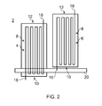
- a stress wave 20 approaches the strain gauge assembly 2 at a speed C commensurate with the wave type and material properties of the test component. As shown in Figure 2 , the stress wave 20 impinges on the first strain gauge 4 before reaching the second strain gauge 6 because of the offset doff between the first and second strain gauges 4, 6. The stress wave 20 causes a small portion of the first strain gauge 4 to be placed under tension or compression thus changing the resistance of the conductor 14 and producing a signal.
- the stress wave 20 After a time interval ⁇ T, the stress wave 20 reaches the second strain gauge 6 and similarly the stress wave 20 causes a small portion of the second strain gauge 6 to be placed under tension or compression thus changing the resistance of the conductor 14 and producing a signal.
- Figure 4(a) shows a graph of the signal output by the first strain gauges 4 as a function of time.
- the signal output by the first strain gauge 4 has a ramp-up portion where the signal increases until the stress wave 20 is entirely within the first strain gauge 4. However, once the stress wave 20 is entirely within the first strain gauge 4, the reading plateaus at a constant level until the stress wave 20 begins to exit the area of the first strain gauge 4. At this point, the signal displays a ramp-down portion where the signal decreases to zero when the stress wave has completely exited the first strain gauge 4.
- the signal from the second strain gauge 6 is shown in Figure 4(b) .
- the signal from the second strain gauge 6 is identical to that of the first strain gauge 4 but lags the signal of the first strain gauge 4 by the time interval ⁇ T.
- the signals from the first and second strain gauges 4, 6 also indicate the direction of the stress wave 20 since the stress wave 20 arrives at the first strain gauge 4 before arriving at the second strain gauge 6.
- the signals from the first and second strain gauges 4, 6 are processed by the signal processor in order to combine them.
- Figure 4(c) shows the processed signals from the first and second strain gauges 4, 6, where the signals have been added to one other.
- the combined signal ramps up to a lower plateau as per the signal of the first strain gauge 4.
- This lower plateau has a duration which is equal to the time interval ⁇ T.
- the contribution from the second strain gauge 6 causes the signal to again increase before reaching a higher plateau.
- the stress wave 20 exits the first strain gauge the signal ramps down to the lower plateau, which again has a duration equal to the time interval ⁇ T, before ramping down to zero when the stress wave 20 exits the second strain gauge 6.
- the processed signal therefore provides a simple means of extracting the time interval ⁇ T.
- Figure 4(d) shows an alternative method of processing the signals from the first and second strain gauges 4, 6 where the signals are subtracted from one another.
- the combined signal ramps up to a plateau as per the signal of the first strain gauge 4.
- the plateau has a duration which is equal to the time interval ⁇ T.
- the contribution from the second strain gauge 6 causes the signal to ramp down to zero.
- the signal remains at zero until the stress wave 20 exits the first strain gauge causing the signal to ramp down to a negative plateau, which again has a duration equal to the time interval ⁇ T.
- the signal ramps up to zero when the stress wave 20 exits the second strain gauge 6.
- the processed signal therefore provides a simple means of extracting the time interval ⁇ T.
- the positive first plateau and negative second plateau indicates that the stress wave 20 reached the first strain gauge 4 before reaching the second strain gauge 6 and therefore readily displays the direction of the stress wave 20.
- a shock wave typically comprises a continuum of waves over a range of frequencies which, in general, have dispersive characteristics: the wave speed is a function of the wave frequency. More sophisticated signal processing may be employed to determine group and phase velocity, and to deduce the dispersion relation for the particular material and structure under test. It is believed that assemblies of more than two strain gauges may be necessary to make accurate assessments of these dispersive effects.
- the strain gauge assembly comprises a transmitter 101 for transmitting, for example using wireless or wired communications techniques, the raw signals from the first and second strain gauges 4, 6, processed signals from the signal processor 102 and/or determined properties to a receiver.
- Figure 5 depicts a number of options in practice it is unlikely that all options will be used simultaneously. This allows remote sensing of the strain of a component and thus can be used whilst the component is in service.
- the power for the signal processor and/or transmitter can be harnessed from the energy of the stress wave 20 being measured, or from previous wave activity, using an energy conversion means. Where the energy of a previous wave activity is used it may be desirable to store the energy in an appropriate rechargeable battery or capacitor. Using stored energy may be desirable where the energy obtained from a single pulse is not sufficient or not available in time for it to be used immediately in the signal processor.
- the first and second strain gauges 4, 6 are of different length. Therefore, one of the first and second ends 10, 12 of the first and second strain gauges 4, 6 can be aligned whilst the other of the first and second ends 10, 12 are offset from one another. Consequently, the stress wave 20 either enters or exits the first and second strain gauges 4, 6 at different times, allowing the time interval ⁇ T to be calculated.
- the Split Hopkinson bar test uses two lengths of bar arranged in series with a specimen sandwiched between the two bars. A longitudinal shock pulse is transmitted down a rod and the shock pulse is transmitted from the first bar, through the specimen, and into the second bar.
- the shape and material choice of the bar ensures that the wave pulse is almost entirely a wave guided 1-D compression or tension wave with well defined speed and behaviour.
- the bars can be constructed from lower stiffness materials. Usually they are of brass or steel; materials with good linear elastic properties. However using materials with lower stiffness usually means increasing issues of viscosity and other non-linear effects.
- the strain gauge assembly of the present invention could be a useful diagnostic and/or filter tool.
- the present invention has been shown as having separate backing layers 8 for the first and second strain gauges 4, 6, in an alternative embodiment they may be integrally formed or mounted on an additional backing layer to join them to one another.
- the strain gauge assembly is to be mounted around the perimeter of a component which has a uniform cross-section along at least the length of the strain gauge assembly
- the alignment feature may be the sides of the backing layer itself.
- the backing layer may be sized to overlap when wrapped around the perimeter of the component so that the sides of the backing layer which extend around the perimeter are aligned when the assembly is aligned with the axis.
- the assembly may be sized so that the sides just meet when wrapped around the component.
- the sides which lie in the direction of the axis are parallel if the strain gauge assembly is aligned with the axis of the component.
- lines or other indications may be printed or otherwise formed on the backing layer, but essentially function in the same manner as the sides of the backing layer.
- the backing layer may be transparent or translucent so that the alignment feature is still visible even when the other end of the backing layer has been wrapped over it. Such alignment features are particularly useful in the application of the strain gauge assembly in the split Hopkinson bar test described above.
- alternative signal processing techniques include FFT (fast Fourier transform) and other types of transform such as Chirp transform methods and wavelet methods.
- each successive strain gauge may be offset by a greater amount.
- the strain gauges need not be arranged in such a staggered configuration and could be randomly offset.
- there are more than two strain gauges not all strain gauges need be offset and some may be aligned. However, there must be at least one strain gauge which is offset from another strain gauge.
- the gauges can also be used to detect the presence of a curved wave front, and its shape, by cross-referencing the signals from multiple gauges.
- the wave 20 may be a single pulse or a wave packet, however regardless of the type, the wave 20 should be short in duration such that it may be completely contained within the first and second strain gauges 4, 6. Such a wave is typical of a shock load event.
- strain gauges such as piezoresistors, or fibre optic sensors may be used.
Abstract
Description
- The present invention relates to a strain gauge assembly and method, and particularly but not exclusively to an assembly and method for measuring a stress wave in a composite material.
- A strain gauge typically comprises a conductor, such as a thin foil, arranged in a serpentine pattern. The pattern is such that the conductor extends along a length and doubles back on itself. This is repeated to form a plurality of parallel lengths.
- The conductor is conventionally laid upon a flexible backing layer made from an insulative material. The backing layer isolates the conductor from a test component in which strain is to be measured. However, where the test component itself is an insulative material, the backing layer may be omitted. The strain gauge is affixed to the test component using an adhesive or other means of fixation.
- The resistance of the conductor is measured in order to determine the strain of the test component. The resistance of the conductor varies depending on whether it is under compression or tension. When in compression, the length of the conductor decreases and its thickness increases, thus decreasing the resistance measured. Conversely, when in tension, the length of the conductor increases and its thickness decreases, which increases the resistance measured.
- The change in length and thickness undergone during strain is experienced along each of the lengths of the conductor. Consequently, the change in resistance is multiplied by the number of lengths in the serpentine pattern. Therefore, the pattern amplifies the change in resistance measured, thus making the gauge far more sensitive.
- Two strain gauges may be used to obtain a full surface 2D strain field. To achieve this, the two strain gauges are arranged perpendicular to each other. To improve the accuracy of this method, a third strain gauge may be included at an angle of 45 degrees to the other two strain gauges. This accounts for any misalignment between the strain gauges.
- To improve the accuracy of the measurements, a "rosette" of strain gauges may be used to cancel out any voltage/current effects. Essentially, a strain gauge works as a variable resistor, and therefore they may be used to form a Wheatstone bridge. This provides a more sensitive and accurate measurement.
- Generally, strain gauges are used for measuring strains that are slowly varying across the surface of the test component, and where the surface stresses are reasonably representative of the stresses that would be seen on the inside of the material of the component.
- A component constructed from a composite material displays a different local strain adjacent to a fibre than in a region between fibres. It is conventional to use a larger strain gauge than usual, covering a large area of material, so as to average out such local strain variations. However, this is recognised to be a crude approach with limited value since it does not provide a detailed picture of the strain field across the surface.
- It is an object of the present invention to seek to provide an improved strain gauge assembly.
- In accordance with an aspect of the invention there is provided a strain gauge assembly comprising: a plurality of identical strain gauges arranged in a parallel side-by-side relationship, each
having a first end and a second end; wherein the first and/or second end of one of the plurality of strain gauges is offset from a corresponding first and/or second end of another of the plurality of strain gauges. - By identical it is meant that the gauges are of substantially the same design, size and length and if interchanged would offer no significant difference in the operation of the invention.
- For a single strain gauge, there is no means to differentiate between a long duration low amplitude wave and a shorter duration high amplitude wave. The present invention allows the duration of the wave to be determined, providing an indication of the amplitude of the wave.
- The present invention may be particularly useful for investigating the propagation of shock wave fronts through a composite material, especially through thickness shock.
- A specific application of the invention may be in a split Hopkinson bar test.
- The plurality of strain gauges may be individual components and may be arranged by hand on the test component. The strain gauges may be arranged using simple positioning tools. Alternatively, the strain gauges may be integrally formed to allow easy positioning of the strain gauges on the test component.
- The plurality of strain gauges may be substantially parallel with one another.
- The offset may be a predetermined distance.
- Each of the plurality of strain gauges may be of the same length.
- The offset may be a fraction of the length of the gauges. For example the offset may be 1/2, 1/3, 2/5, ...n/m...ofthe length of the gauges. Alternatively, the offset may be random.
- The strain gauge assembly may further comprise a flexible backing layer, and the plurality of strain gauges may be mounted on the backing layer.
- The backing layer may comprise an alignment feature for aligning the strain gauge assembly with an axis of a test component.
- The alignment feature may comprise two parallel features on the backing layer which may align when the strain gauge assembly is aligned with the axis of the test component.
- The parallel features may be sides of the backing layer.
- The parallel features may be markings on the backing layer.
- The parallel features may be aligned parallel or perpendicular to an axis of the plurality of strain gauges extending between the first and second ends.
- The strain gauge assembly may further comprise a signal processor which processes signals from the plurality of strain gauges.
- The signal processor may add or subtract the signals from the plurality of strain gauges.
- The signal processor may determine properties of a stress wave in a test component.
- The properties of the stress wave determined by the signal processor may be one or more of: speed, duration, amplitude, shape, group velocity, phase velocity and dispersion relation.
- The signal processor may be powered by a stress wave, which may be the stress wave that is being measured, or energy stored from previous stress waves.
- The assembly may further comprise a transmitter which transmits signals from the plurality of strain gauges to a receiver.
- The signals may be the raw signals from the strain gauges, the processed signals and/or the determined properties of the wave.
- The transmitter may be powered by a stress wave, which may be the stress wave that is being measured, or energy stored from previous stress waves.
- The transmitter may send the signals by radio or other wireless technology to a remote receiver. For example the remote receiver may be a computer in an aircraft cockpit, or a computer on the test bed. Alternatively, the transmitter may send the signals down a wired connection to the remote receiver. The signals may be collated or stored before transmission which may be in real-time or at intervals.
- The signal processing algorithms may be built as hardware within the same circuit as the strain gauges, and this may have potential to be embedded or attached to components that are not only used for test, but also during their service lives for monitoring the loading conditions in real time.
- One or more strain gauge assemblies may be used to form a strain gauge rosette. The rosette may contain the strain gauge assembly of the present invention and standard strain gauges.
- The strain gauge assembly may be printed onto the component.
- For particular classes of test or in-service component, the strain gauge assembly and associated circuitry may be printed directly onto the surface (or subsurface during earlier manufacturing phase) of the component. This may be applicable to the manufacture of parts made from non-electrically conducting material. It may also be applicable to parts where a part of the component is non-electrically conducting. It may also be applicable if an insulating layer may be laid down prior to and after the printing of the strain gauge and associated electronics. Such applications may include: a composite fan blade, a composite containment casing, a composite guide vane, a composite structure or a composite shaft. These are all components for which extreme service loads (bird strike, Fan Blade Off (FBO) or Foreign Object Damage (FOD) events) and extreme consequences (e.g. High Cycle Fatigue (HCF) failure following an unanticipated damage event, leading to failure of a critical component) need to be monitored. The strain gauge assembly may be embedded during the lay-up of a composite component, which may ensure precise positioning of the assembly based on the precision of the manufacturing geometric control systems.
- In accordance with another aspect of the invention there is provided a method for determining strain properties in a test component, the method comprising: providing a plurality of strain gauges, each having a first end and a second end; arranging the plurality of strain gauges on the test component in a side-by-side relationship such the first and/or second end of one of the plurality of strain gauges is offset from a corresponding first and/or second end of another of the plurality of strain gauges.
- The method may further comprise processing signals from the plurality of strain gauges.
- Processing the signals may comprise adding or subtracting the signals from the plurality of strain gauges.
- Processing the signals may comprise determining properties of a stress wave in the test component.
- The properties of the stress wave determined may be one or more of: speed, duration, amplitude, shape, group velocity, phase velocity and dispersion relation.
- For a better understanding of the present invention and to show more clearly how it may be carried into effect, reference will now be made, by way of example, to the accompanying drawings, in which:-
-
Figure 1 is a plan view of a strain gauge assembly in accordance with an embodiment of the invention comprising first and second strain gauges, with a wave pulse approaching; -
Figure 2 is a plan view of the strain gauge assembly with the wave pulse having entered the first strain gauge; -
Figure 3 is a plan view of the strain gauge assembly with the wave pulse having entered the second strain gauge; -
Figure 4(a) is a graph showing the signal output by the first strain gauge as a function of time; -
Figure 4(b) is a graph showing the signal output by the second strain gauge as a function of time; -
Figure 4(c) is a graph showing the processed signals from the first and second strain gauges, where the signals have been added to one another; and -
Figure 4(d) is a graph showing the processed signals from the first and second strain gauges, where the signals have been subtracted from one another. -
Figure 5 depicts arrangements of strain gauge, signal processors and / or signal transmitters. -
Figure 1 shows astrain gauge assembly 2 in accordance with an embodiment of the invention. Thestrain gauge assembly 2 comprises afirst strain gauge 4 and asecond strain gauge 6. - Each of the first and
second strain gauges flexible backing layer 8 made from an insulative material. Thebacking layer 8 is substantially rectangular and has afirst end 10 and asecond end 12 each corresponding to a short side of thebacking layer 8. - A
conductor 14, such as a thin foil, is laid down on top of thebacking layer 8. Theconductor 14 has afirst end 16 and asecond end 18, and is arranged in a serpentine pattern between the first and second ends 16, 18. In the preferred arrangement the pattern is such that theconductor 14 extends from thefirst end 10 of thebacking layer 8 along substantially the entire length of a long side of thebacking layer 8 and doubles back on itself before running back towards thesecond end 12 of thebacking layer 8. This is repeated to form a plurality of parallel lengths. Other arrangements may be used, for example doubling up the conductor so that any AC induction effects are minimised at the turns. Doubling up enables a spiral arrangement to be used including a range of other multiple spirals. - The resistance of the
conductor 14 is measured between the first and second ends 16, 18 of theconductor 14 in order to determine the strain of the test component. The first andsecond strain gauges second strain gauges second strain gauges - The
backing layer 8 isolates theconductor 14 from a test component (not shown) in which strain is to be measured. However, where the test component itself is an insulative material, the backing layer may be omitted. Thestrain gauge assembly 2 is affixed to the test component using an adhesive or other means of fixation, or "printed" on directly for example using techniques like vapour depositioning or from an "ink-jet" printhead. - The first and
second strain gauges first strain gauge 4 facing one of the long sides of thesecond strain gauge 6. The first andsecond strain gauges - The first and
second strain gauges second strain gauges second strain gauges - In use, a
stress wave 20 approaches thestrain gauge assembly 2 at a speed C commensurate with the wave type and material properties of the test component. As shown inFigure 2 , thestress wave 20 impinges on thefirst strain gauge 4 before reaching thesecond strain gauge 6 because of the offset doff between the first andsecond strain gauges stress wave 20 causes a small portion of thefirst strain gauge 4 to be placed under tension or compression thus changing the resistance of theconductor 14 and producing a signal. - After a time interval ΔT, the
stress wave 20 reaches thesecond strain gauge 6 and similarly thestress wave 20 causes a small portion of thesecond strain gauge 6 to be placed under tension or compression thus changing the resistance of theconductor 14 and producing a signal. -
Figure 4(a) shows a graph of the signal output by thefirst strain gauges 4 as a function of time. The signal output by thefirst strain gauge 4 has a ramp-up portion where the signal increases until thestress wave 20 is entirely within thefirst strain gauge 4. However, once thestress wave 20 is entirely within thefirst strain gauge 4, the reading plateaus at a constant level until thestress wave 20 begins to exit the area of thefirst strain gauge 4. At this point, the signal displays a ramp-down portion where the signal decreases to zero when the stress wave has completely exited thefirst strain gauge 4. - The signal from the
second strain gauge 6 is shown inFigure 4(b) . The signal from thesecond strain gauge 6 is identical to that of thefirst strain gauge 4 but lags the signal of thefirst strain gauge 4 by the time interval ΔT. - The signals from the first and
second strain gauges stress wave 20 can be determined since C = doff/ΔT. Furthermore, once the speed C of thestress wave 20 is known, its duration may be calculated from the duration of the ramp-up and/or ramp-down portions of the signal of the first and/orsecond strain gauges stress wave 20 to provide an indication of the amplitude of thestress wave 20. The signals from the first andsecond strain gauges stress wave 20 since thestress wave 20 arrives at thefirst strain gauge 4 before arriving at thesecond strain gauge 6. - To enable this information to be more easily extracted, the signals from the first and
second strain gauges Figure 4(c) shows the processed signals from the first andsecond strain gauges first strain gauge 4. This lower plateau has a duration which is equal to the time interval ΔT. After this time the contribution from thesecond strain gauge 6 causes the signal to again increase before reaching a higher plateau. When thestress wave 20 exits the first strain gauge the signal ramps down to the lower plateau, which again has a duration equal to the time interval ΔT, before ramping down to zero when thestress wave 20 exits thesecond strain gauge 6. The processed signal therefore provides a simple means of extracting the time interval ΔT. -
Figure 4(d) shows an alternative method of processing the signals from the first andsecond strain gauges first strain gauge 4. The plateau has a duration which is equal to the time interval ΔT. After this time the contribution from thesecond strain gauge 6 causes the signal to ramp down to zero. The signal remains at zero until thestress wave 20 exits the first strain gauge causing the signal to ramp down to a negative plateau, which again has a duration equal to the time interval ΔT. Following the negative plateau, the signal ramps up to zero when thestress wave 20 exits thesecond strain gauge 6. The processed signal therefore provides a simple means of extracting the time interval ΔT. Also, the positive first plateau and negative second plateau indicates that thestress wave 20 reached thefirst strain gauge 4 before reaching thesecond strain gauge 6 and therefore readily displays the direction of thestress wave 20. - A shock wave typically comprises a continuum of waves over a range of frequencies which, in general, have dispersive characteristics: the wave speed is a function of the wave frequency. More sophisticated signal processing may be employed to determine group and phase velocity, and to deduce the dispersion relation for the particular material and structure under test. It is believed that assemblies of more than two strain gauges may be necessary to make accurate assessments of these dispersive effects.
- In a particular embodiment of the invention, shown in
Figure 5 , the strain gauge assembly comprises atransmitter 101 for transmitting, for example using wireless or wired communications techniques, the raw signals from the first andsecond strain gauges signal processor 102 and/or determined properties to a receiver.Figure 5 depicts a number of options in practice it is unlikely that all options will be used simultaneously. This allows remote sensing of the strain of a component and thus can be used whilst the component is in service. - The power for the signal processor and/or transmitter can be harnessed from the energy of the
stress wave 20 being measured, or from previous wave activity, using an energy conversion means. Where the energy of a previous wave activity is used it may be desirable to store the energy in an appropriate rechargeable battery or capacitor. Using stored energy may be desirable where the energy obtained from a single pulse is not sufficient or not available in time for it to be used immediately in the signal processor. - In an alternative embodiment of the invention, the first and
second strain gauges second strain gauges stress wave 20 either enters or exits the first andsecond strain gauges - A specific application of the present invention to a split Hopkinson bar test will now be described.
- The Split Hopkinson bar test uses two lengths of bar arranged in series with a specimen sandwiched between the two bars. A longitudinal shock pulse is transmitted down a rod and the shock pulse is transmitted from the first bar, through the specimen, and into the second bar. The shape and material choice of the bar ensures that the wave pulse is almost entirely a wave guided 1-D compression or tension wave with well defined speed and behaviour. For specimens with more compliant material properties (e.g. composites), the bars can be constructed from lower stiffness materials. Usually they are of brass or steel; materials with good linear elastic properties. However using materials with lower stiffness usually means increasing issues of viscosity and other non-linear effects. Furthermore, this may contaminate the 1-D signal as a result of Poisson's effect (a wave pulse of radial expansion of the rod). To overcome these issues it is necessary to filter the signals, and the strain gauge assembly of the present invention could be a useful diagnostic and/or filter tool.
- Although the present invention has been shown as having
separate backing layers 8 for the first andsecond strain gauges - Although additive and subtractive signal processing techniques have been described, other techniques could be used to allow useful information to be extracted from the signals of the first and
second strain gauges - The present invention has been described with reference to a
strain gauge assembly 2 comprising first andsecond strain gauges - Where a large number of strain gauges are used there has to be an assumption that the wave front of the stress wave is comparatively wide, such that the front is parallel at the incidence with the gauges. However, the gauges can also be used to detect the presence of a curved wave front, and its shape, by cross-referencing the signals from multiple gauges.
- The
wave 20 may be a single pulse or a wave packet, however regardless of the type, thewave 20 should be short in duration such that it may be completely contained within the first andsecond strain gauges - Although the present invention has been described with reference to conventional foil strain gauges, the invention may be applied to other types of strain gauge. For example, semiconductor strain gauges, such as piezoresistors, or fibre optic sensors may be used.
Claims (15)
- A strain gauge assembly comprising:a plurality of identical strain gauges (4,6) arranged in a parallel side-by-side relationship, each having a first end and a second end;wherein the first (10) and second (12) end of one of the plurality of strain gauges is offset (doff) from a corresponding first (10) and second (12) end of another of the plurality of strain gauges.
- A strain gauge assembly as claimed in any one of the preceding claims, wherein the offset is a fraction of the length of the gauges.
- A strain gauge assembly as claimed in any one of the preceding claims, further comprising a flexible backing layer (2), wherein the plurality of strain gauges are mounted on the backing layer.
- A strain gauge assembly as claimed in claim 3, wherein the backing layer comprises an alignment feature for aligning the strain gauge assembly with an axis of a test component.
- A strain gauge assembly as claimed in claim 4, wherein the alignment feature comprises two parallel features on the backing layer which align when the strain gauge assembly is aligned with the axis of the test component.
- A strain gauge assembly as claimed in any one of the preceding claims, further comprising a signal processor which processes signals from the plurality of strain gauges.
- A strain gauge assembly as claimed in claim 6, wherein the signal processor determines properties of a stress wave in a test component.
- A strain gauge assembly as claimed in claim 7, wherein the properties of the stress wave determined by the signal processor are one or more of: speed, duration, amplitude, shape, group velocity, phase velocity and dispersion relation.
- A strain gauge assembly as claimed in any one of claims 6 to 8, wherein the signal processor is powered by a stress wave (20) measurable by the plurality of strain gauges.
- A strain gauge assembly as claimed in any one of the preceding claims, further comprising a transmitter which transmits signals from the plurality of strain gauges to a receiver.
- A strain gauge rosette comprising one or more strain gauge assemblies as claimed in any one of the preceding claims.
- A component comprising a strain gauge assembly as claimed in any one of the preceding claims, wherein the strain gauge assembly is printed onto the component.
- A method for determining strain properties in a test component, the method characterised in that it comprises:providing a plurality of strain gauges (4,6), each having a first end (10) and a second end (12);arranging the plurality of strain gauges on the test component in a side-by-side relationship such the first and/or second end of one of the plurality of strain gauges is offset from a corresponding first and/or second end of another of the plurality of strain gauges and the plurality of strain gauges are aligned to measure a stress wave in the component.
- A method as claimed in claim 13, further comprising:processing signals from the plurality of strain gauges.
- A method as claimed in claim 14, wherein processing the signals comprises determining properties of a stress wave in the test component.
Applications Claiming Priority (1)
| Application Number | Priority Date | Filing Date | Title |
|---|---|---|---|
| GBGB1004224.0A GB201004224D0 (en) | 2010-03-15 | 2010-03-15 | A strain assembly and method |
Publications (2)
| Publication Number | Publication Date |
|---|---|
| EP2369292A1 true EP2369292A1 (en) | 2011-09-28 |
| EP2369292B1 EP2369292B1 (en) | 2017-05-03 |
Family
ID=42261544
Family Applications (1)
| Application Number | Title | Priority Date | Filing Date |
|---|---|---|---|
| EP11156656.8A Not-in-force EP2369292B1 (en) | 2010-03-15 | 2011-03-02 | A Strain Gauge Assembly and Method |
Country Status (3)
| Country | Link |
|---|---|
| US (1) | US8650966B2 (en) |
| EP (1) | EP2369292B1 (en) |
| GB (1) | GB201004224D0 (en) |
Cited By (2)
| Publication number | Priority date | Publication date | Assignee | Title |
|---|---|---|---|---|
| WO2013140085A1 (en) * | 2012-03-20 | 2013-09-26 | Snecma | Detection and tracking of damage or impact of a foreign object on an aircraft engine fan |
| FR3076594A1 (en) * | 2018-01-08 | 2019-07-12 | L'air Liquide, Societe Anonyme Pour L'etude Et L'exploitation Des Procedes Georges Claude | BOTTLE AND DEVICE FOR STORING FLUID UNDER PRESSURE |
Families Citing this family (11)
| Publication number | Priority date | Publication date | Assignee | Title |
|---|---|---|---|---|
| US9090304B2 (en) * | 2012-08-27 | 2015-07-28 | Shimano Inc. | Bicycle control device |
| US20150296607A1 (en) * | 2014-04-11 | 2015-10-15 | Apple Inc. | Electronic Device With Flexible Printed Circuit Strain Gauge Sensor |
| US20150296622A1 (en) * | 2014-04-11 | 2015-10-15 | Apple Inc. | Flexible Printed Circuit With Semiconductor Strain Gauge |
| CA2960106A1 (en) * | 2014-09-08 | 2016-03-17 | Fike Corporation | Pressure relief device having conductive ink sensors formed thereon |
| JP6373778B2 (en) * | 2015-03-11 | 2018-08-15 | アルプス電気株式会社 | Load sensor and load detection device |
| KR102544041B1 (en) * | 2015-03-31 | 2023-06-15 | 가부시키가이샤 네지로 | Conducting path sub-materials, patterning method of current path, method of measuring member change |
| ITTO20150046U1 (en) * | 2015-04-10 | 2016-10-10 | Guido Maisto | DEVICE FOR DETECTION OF DEFORMATIONS AND TRANSMISSION OF THE DETECTED DATA |
| JP6546075B2 (en) * | 2015-11-25 | 2019-07-17 | 日本電信電話株式会社 | Detection method |
| GB201611524D0 (en) | 2016-07-01 | 2016-08-17 | Rolls Royce Plc | Rotor blade damage |
| US10247970B2 (en) | 2016-12-20 | 2019-04-02 | Microsoft Technology Licensing, Llc | Measuring strain on display device |
| US10352789B2 (en) | 2017-02-09 | 2019-07-16 | Microsoft Technology Licensing, Llc | Measuring strain on display device |
Citations (5)
| Publication number | Priority date | Publication date | Assignee | Title |
|---|---|---|---|---|
| US6986287B1 (en) * | 2002-09-30 | 2006-01-17 | Nanodynamics Inc. | Method and apparatus for strain-stress sensors and smart skin for aircraft and space vehicles |
| US20070018083A1 (en) * | 2005-06-13 | 2007-01-25 | Acellent Technologies, Inc. | Structural health monitoring layer having distributed electronics |
| US20070095160A1 (en) * | 2005-11-03 | 2007-05-03 | The Boeing Company | Structural assessment and monitoring system and associated method |
| US20070255424A1 (en) * | 2006-04-28 | 2007-11-01 | Leydet Michael G | Prosthetic sensing systems and methods |
| US20080223152A1 (en) * | 2005-12-14 | 2008-09-18 | The Boeing Company | Methods and systems for using active surface coverings for structural assessment and monitoring |
Family Cites Families (13)
| Publication number | Priority date | Publication date | Assignee | Title |
|---|---|---|---|---|
| GB1148877A (en) | 1965-04-21 | 1969-04-16 | Fairey Surveys Ltd | Improvements relating to strain gauge assemblies |
| US3994598A (en) * | 1975-09-15 | 1976-11-30 | Reytblatt Zinovy V | Photoelastic strain gauge coating |
| FR2603378B1 (en) | 1986-08-29 | 1988-12-02 | Seb Sa | TEST BODY, IN PARTICULAR FOR A WEIGHING APPARATUS |
| US5289721A (en) * | 1990-09-10 | 1994-03-01 | Nippondenso Co., Ltd. | Semiconductor pressure sensor |
| FR2667150A1 (en) | 1990-09-24 | 1992-03-27 | Dal Dan Felice | Strain gauge with multiple outputs |
| US6951143B1 (en) | 2000-11-28 | 2005-10-04 | Michelin Recherche Et Technique S.A. | Three-axis sensor assembly for use in an elastomeric material |
| JP4114044B2 (en) | 2001-07-17 | 2008-07-09 | トヨタ自動車株式会社 | Tire acting force detection device |
| US6748810B2 (en) * | 2002-02-11 | 2004-06-15 | Bill Christensen | Load sensor |
| US7096748B2 (en) * | 2004-07-28 | 2006-08-29 | Lsi Logic Corporation | Embedded strain gauge in printed circuit boards |
| US20060185446A1 (en) * | 2005-02-18 | 2006-08-24 | Speckhart Frank H | Printed strain gage for vehicle seats |
| JP4758271B2 (en) * | 2006-04-18 | 2011-08-24 | 株式会社共和電業 | Strain gauge for large strain measurement |
| JP4887260B2 (en) * | 2006-10-31 | 2012-02-29 | アイシン精機株式会社 | Passenger load sensor for vehicle seat |
| US20110075387A1 (en) | 2008-05-21 | 2011-03-31 | Homer Steven S | Strain Measurement Chips For Printed Circuit Boards |
-
2010
- 2010-03-15 GB GBGB1004224.0A patent/GB201004224D0/en not_active Ceased
-
2011
- 2011-03-02 EP EP11156656.8A patent/EP2369292B1/en not_active Not-in-force
- 2011-03-02 US US13/038,830 patent/US8650966B2/en not_active Expired - Fee Related
Patent Citations (5)
| Publication number | Priority date | Publication date | Assignee | Title |
|---|---|---|---|---|
| US6986287B1 (en) * | 2002-09-30 | 2006-01-17 | Nanodynamics Inc. | Method and apparatus for strain-stress sensors and smart skin for aircraft and space vehicles |
| US20070018083A1 (en) * | 2005-06-13 | 2007-01-25 | Acellent Technologies, Inc. | Structural health monitoring layer having distributed electronics |
| US20070095160A1 (en) * | 2005-11-03 | 2007-05-03 | The Boeing Company | Structural assessment and monitoring system and associated method |
| US20080223152A1 (en) * | 2005-12-14 | 2008-09-18 | The Boeing Company | Methods and systems for using active surface coverings for structural assessment and monitoring |
| US20070255424A1 (en) * | 2006-04-28 | 2007-11-01 | Leydet Michael G | Prosthetic sensing systems and methods |
Cited By (8)
| Publication number | Priority date | Publication date | Assignee | Title |
|---|---|---|---|---|
| WO2013140085A1 (en) * | 2012-03-20 | 2013-09-26 | Snecma | Detection and tracking of damage or impact of a foreign object on an aircraft engine fan |
| FR2988444A1 (en) * | 2012-03-20 | 2013-09-27 | Snecma | DETECTION OF A FOREIGN OBJECT IMPACT AT THE ENTRANCE OF AN AIRCRAFT ENGINE |
| CN104204414A (en) * | 2012-03-20 | 2014-12-10 | 斯奈克玛 | Detection and tracking of damage or impact of a foreign object on an aircraft engine fan |
| CN104204414B (en) * | 2012-03-20 | 2016-08-31 | 斯奈克玛 | Detect and follow the trail of damage or the foreign body impact to it of aeronautical engine blower fan |
| RU2625412C2 (en) * | 2012-03-20 | 2017-07-13 | Снекма | Detection and tracking of aircraft engine fan damage or collision of foreign object with it |
| EP3287600A1 (en) * | 2012-03-20 | 2018-02-28 | Safran Aircraft Engines | Aircraft engine fan provided with a system for detecting and tracking an object impact |
| US9926937B2 (en) | 2012-03-20 | 2018-03-27 | Snecma | Detecting and tracking damage to an aeroengine fan or an impact of a foreign object thereagainst |
| FR3076594A1 (en) * | 2018-01-08 | 2019-07-12 | L'air Liquide, Societe Anonyme Pour L'etude Et L'exploitation Des Procedes Georges Claude | BOTTLE AND DEVICE FOR STORING FLUID UNDER PRESSURE |
Also Published As
| Publication number | Publication date |
|---|---|
| EP2369292B1 (en) | 2017-05-03 |
| GB201004224D0 (en) | 2010-04-28 |
| US20110219883A1 (en) | 2011-09-15 |
| US8650966B2 (en) | 2014-02-18 |
Similar Documents
| Publication | Publication Date | Title |
|---|---|---|
| EP2369292B1 (en) | A Strain Gauge Assembly and Method | |
| EP3213045B1 (en) | Method and system for structural health monitoring with frequency synchronization | |
| US7849752B2 (en) | Method and system for passive wireless strain gauge | |
| CN102680578B (en) | Structural healthy monitoring system | |
| EP2593672B1 (en) | Ice detection method and system for wind turbine blades | |
| US20090326834A1 (en) | Systems, methods and computer program products for characterizing structural events | |
| Na et al. | Resonant frequency range utilized electro-mechanical impedance method for damage detection performance enhancement on composite structures | |
| EP3112857A2 (en) | Ultrasonic test system, ultrasonic test method and aircraft structural object | |
| US20060106550A1 (en) | Structural health management system and method for enhancing availability and integrity in the structural health management system | |
| JP2011191230A (en) | Damage diagnosis system and damage diagnosis method | |
| US7719694B1 (en) | System and method of surface wave imaging to detect ice on a surface or damage to a surface | |
| CN109580057A (en) | Lifting airscrew load monitoring system and method based on Built-In Optical-Fiber Sensors Used | |
| CN104730152A (en) | Fractal dimension-based method of monitoring crack damage of composite structural member | |
| Maruo et al. | Electromechanical impedance-based structural health monitoring instrumentation system applied to aircraft structures and employing a multiplexed sensor array | |
| CN103968939A (en) | Transformer winding looseness fault detection method based on average displacement method | |
| Ksica et al. | Integration and test of piezocomposite sensors for structure health monitoring in aerospace | |
| Jilani et al. | Static strain modelling, calibration, and measurements for high-temperature wireless SAW resonator operation | |
| Liu et al. | A validation study for a SHM technology under operational environment | |
| CN103827648A (en) | Method and arrangement for monitoring gearwheels during operation | |
| Pullin et al. | On the development of a damage detection system using macro-fibre composite sensors | |
| CN112529041A (en) | Icing quantitative monitoring method and device based on guided wave energy characteristic principal component analysis | |
| EP2363703B1 (en) | Method and apparatus for determining the natural frequency of wooden planks | |
| Keller et al. | Advantages of fiber Bragg gratings for measuring electric motor loadings in aerospace application | |
| Ren et al. | The temperature effects on embedded PZT signals in structural health monitoring for composite structures with different thicknesses | |
| EP4173964A1 (en) | Monitoring system, aircraft, and monitoring method |
Legal Events
| Date | Code | Title | Description |
|---|---|---|---|
| PUAI | Public reference made under article 153(3) epc to a published international application that has entered the european phase |
Free format text: ORIGINAL CODE: 0009012 |
|
| AK | Designated contracting states |
Kind code of ref document: A1 Designated state(s): AL AT BE BG CH CY CZ DE DK EE ES FI FR GB GR HR HU IE IS IT LI LT LU LV MC MK MT NL NO PL PT RO RS SE SI SK SM TR |
|
| AX | Request for extension of the european patent |
Extension state: BA ME |
|
| 17P | Request for examination filed |
Effective date: 20120328 |
|
| 17Q | First examination report despatched |
Effective date: 20150219 |
|
| RAP1 | Party data changed (applicant data changed or rights of an application transferred) |
Owner name: ROLLS-ROYCE PLC |
|
| GRAP | Despatch of communication of intention to grant a patent |
Free format text: ORIGINAL CODE: EPIDOSNIGR1 |
|
| INTG | Intention to grant announced |
Effective date: 20170213 |
|
| GRAS | Grant fee paid |
Free format text: ORIGINAL CODE: EPIDOSNIGR3 |
|
| GRAA | (expected) grant |
Free format text: ORIGINAL CODE: 0009210 |
|
| AK | Designated contracting states |
Kind code of ref document: B1 Designated state(s): AL AT BE BG CH CY CZ DE DK EE ES FI FR GB GR HR HU IE IS IT LI LT LU LV MC MK MT NL NO PL PT RO RS SE SI SK SM TR |
|
| REG | Reference to a national code |
Ref country code: GB Ref legal event code: FG4D |
|
| REG | Reference to a national code |
Ref country code: AT Ref legal event code: REF Ref document number: 890459 Country of ref document: AT Kind code of ref document: T Effective date: 20170515 Ref country code: CH Ref legal event code: EP |
|
| REG | Reference to a national code |
Ref country code: IE Ref legal event code: FG4D |
|
| REG | Reference to a national code |
Ref country code: DE Ref legal event code: R096 Ref document number: 602011037482 Country of ref document: DE |
|
| REG | Reference to a national code |
Ref country code: NL Ref legal event code: MP Effective date: 20170503 |
|
| REG | Reference to a national code |
Ref country code: AT Ref legal event code: MK05 Ref document number: 890459 Country of ref document: AT Kind code of ref document: T Effective date: 20170503 |
|
| REG | Reference to a national code |
Ref country code: LT Ref legal event code: MG4D |
|
| PG25 | Lapsed in a contracting state [announced via postgrant information from national office to epo] |
Ref country code: AT Free format text: LAPSE BECAUSE OF FAILURE TO SUBMIT A TRANSLATION OF THE DESCRIPTION OR TO PAY THE FEE WITHIN THE PRESCRIBED TIME-LIMIT Effective date: 20170503 Ref country code: ES Free format text: LAPSE BECAUSE OF FAILURE TO SUBMIT A TRANSLATION OF THE DESCRIPTION OR TO PAY THE FEE WITHIN THE PRESCRIBED TIME-LIMIT Effective date: 20170503 Ref country code: LT Free format text: LAPSE BECAUSE OF FAILURE TO SUBMIT A TRANSLATION OF THE DESCRIPTION OR TO PAY THE FEE WITHIN THE PRESCRIBED TIME-LIMIT Effective date: 20170503 Ref country code: FI Free format text: LAPSE BECAUSE OF FAILURE TO SUBMIT A TRANSLATION OF THE DESCRIPTION OR TO PAY THE FEE WITHIN THE PRESCRIBED TIME-LIMIT Effective date: 20170503 Ref country code: HR Free format text: LAPSE BECAUSE OF FAILURE TO SUBMIT A TRANSLATION OF THE DESCRIPTION OR TO PAY THE FEE WITHIN THE PRESCRIBED TIME-LIMIT Effective date: 20170503 Ref country code: NO Free format text: LAPSE BECAUSE OF FAILURE TO SUBMIT A TRANSLATION OF THE DESCRIPTION OR TO PAY THE FEE WITHIN THE PRESCRIBED TIME-LIMIT Effective date: 20170803 Ref country code: GR Free format text: LAPSE BECAUSE OF FAILURE TO SUBMIT A TRANSLATION OF THE DESCRIPTION OR TO PAY THE FEE WITHIN THE PRESCRIBED TIME-LIMIT Effective date: 20170804 |
|
| PG25 | Lapsed in a contracting state [announced via postgrant information from national office to epo] |
Ref country code: SE Free format text: LAPSE BECAUSE OF FAILURE TO SUBMIT A TRANSLATION OF THE DESCRIPTION OR TO PAY THE FEE WITHIN THE PRESCRIBED TIME-LIMIT Effective date: 20170503 Ref country code: NL Free format text: LAPSE BECAUSE OF FAILURE TO SUBMIT A TRANSLATION OF THE DESCRIPTION OR TO PAY THE FEE WITHIN THE PRESCRIBED TIME-LIMIT Effective date: 20170503 Ref country code: IS Free format text: LAPSE BECAUSE OF FAILURE TO SUBMIT A TRANSLATION OF THE DESCRIPTION OR TO PAY THE FEE WITHIN THE PRESCRIBED TIME-LIMIT Effective date: 20170903 Ref country code: BG Free format text: LAPSE BECAUSE OF FAILURE TO SUBMIT A TRANSLATION OF THE DESCRIPTION OR TO PAY THE FEE WITHIN THE PRESCRIBED TIME-LIMIT Effective date: 20170803 Ref country code: RS Free format text: LAPSE BECAUSE OF FAILURE TO SUBMIT A TRANSLATION OF THE DESCRIPTION OR TO PAY THE FEE WITHIN THE PRESCRIBED TIME-LIMIT Effective date: 20170503 Ref country code: LV Free format text: LAPSE BECAUSE OF FAILURE TO SUBMIT A TRANSLATION OF THE DESCRIPTION OR TO PAY THE FEE WITHIN THE PRESCRIBED TIME-LIMIT Effective date: 20170503 Ref country code: PL Free format text: LAPSE BECAUSE OF FAILURE TO SUBMIT A TRANSLATION OF THE DESCRIPTION OR TO PAY THE FEE WITHIN THE PRESCRIBED TIME-LIMIT Effective date: 20170503 |
|
| PG25 | Lapsed in a contracting state [announced via postgrant information from national office to epo] |
Ref country code: CZ Free format text: LAPSE BECAUSE OF FAILURE TO SUBMIT A TRANSLATION OF THE DESCRIPTION OR TO PAY THE FEE WITHIN THE PRESCRIBED TIME-LIMIT Effective date: 20170503 Ref country code: DK Free format text: LAPSE BECAUSE OF FAILURE TO SUBMIT A TRANSLATION OF THE DESCRIPTION OR TO PAY THE FEE WITHIN THE PRESCRIBED TIME-LIMIT Effective date: 20170503 Ref country code: RO Free format text: LAPSE BECAUSE OF FAILURE TO SUBMIT A TRANSLATION OF THE DESCRIPTION OR TO PAY THE FEE WITHIN THE PRESCRIBED TIME-LIMIT Effective date: 20170503 Ref country code: EE Free format text: LAPSE BECAUSE OF FAILURE TO SUBMIT A TRANSLATION OF THE DESCRIPTION OR TO PAY THE FEE WITHIN THE PRESCRIBED TIME-LIMIT Effective date: 20170503 Ref country code: SK Free format text: LAPSE BECAUSE OF FAILURE TO SUBMIT A TRANSLATION OF THE DESCRIPTION OR TO PAY THE FEE WITHIN THE PRESCRIBED TIME-LIMIT Effective date: 20170503 |
|
| REG | Reference to a national code |
Ref country code: DE Ref legal event code: R097 Ref document number: 602011037482 Country of ref document: DE |
|
| PG25 | Lapsed in a contracting state [announced via postgrant information from national office to epo] |
Ref country code: SM Free format text: LAPSE BECAUSE OF FAILURE TO SUBMIT A TRANSLATION OF THE DESCRIPTION OR TO PAY THE FEE WITHIN THE PRESCRIBED TIME-LIMIT Effective date: 20170503 Ref country code: IT Free format text: LAPSE BECAUSE OF FAILURE TO SUBMIT A TRANSLATION OF THE DESCRIPTION OR TO PAY THE FEE WITHIN THE PRESCRIBED TIME-LIMIT Effective date: 20170503 |
|
| PLBE | No opposition filed within time limit |
Free format text: ORIGINAL CODE: 0009261 |
|
| STAA | Information on the status of an ep patent application or granted ep patent |
Free format text: STATUS: NO OPPOSITION FILED WITHIN TIME LIMIT |
|
| REG | Reference to a national code |
Ref country code: FR Ref legal event code: PLFP Year of fee payment: 8 |
|
| 26N | No opposition filed |
Effective date: 20180206 |
|
| PG25 | Lapsed in a contracting state [announced via postgrant information from national office to epo] |
Ref country code: SI Free format text: LAPSE BECAUSE OF FAILURE TO SUBMIT A TRANSLATION OF THE DESCRIPTION OR TO PAY THE FEE WITHIN THE PRESCRIBED TIME-LIMIT Effective date: 20170503 |
|
| REG | Reference to a national code |
Ref country code: CH Ref legal event code: PL |
|
| PG25 | Lapsed in a contracting state [announced via postgrant information from national office to epo] |
Ref country code: MC Free format text: LAPSE BECAUSE OF FAILURE TO SUBMIT A TRANSLATION OF THE DESCRIPTION OR TO PAY THE FEE WITHIN THE PRESCRIBED TIME-LIMIT Effective date: 20170503 |
|
| REG | Reference to a national code |
Ref country code: BE Ref legal event code: MM Effective date: 20180331 |
|
| REG | Reference to a national code |
Ref country code: IE Ref legal event code: MM4A |
|
| PG25 | Lapsed in a contracting state [announced via postgrant information from national office to epo] |
Ref country code: LU Free format text: LAPSE BECAUSE OF NON-PAYMENT OF DUE FEES Effective date: 20180302 |
|
| PG25 | Lapsed in a contracting state [announced via postgrant information from national office to epo] |
Ref country code: IE Free format text: LAPSE BECAUSE OF NON-PAYMENT OF DUE FEES Effective date: 20180302 |
|
| PG25 | Lapsed in a contracting state [announced via postgrant information from national office to epo] |
Ref country code: LI Free format text: LAPSE BECAUSE OF NON-PAYMENT OF DUE FEES Effective date: 20180331 Ref country code: BE Free format text: LAPSE BECAUSE OF NON-PAYMENT OF DUE FEES Effective date: 20180331 Ref country code: CH Free format text: LAPSE BECAUSE OF NON-PAYMENT OF DUE FEES Effective date: 20180331 |
|
| PG25 | Lapsed in a contracting state [announced via postgrant information from national office to epo] |
Ref country code: MT Free format text: LAPSE BECAUSE OF NON-PAYMENT OF DUE FEES Effective date: 20180302 |
|
| PG25 | Lapsed in a contracting state [announced via postgrant information from national office to epo] |
Ref country code: TR Free format text: LAPSE BECAUSE OF FAILURE TO SUBMIT A TRANSLATION OF THE DESCRIPTION OR TO PAY THE FEE WITHIN THE PRESCRIBED TIME-LIMIT Effective date: 20170503 |
|
| PGFP | Annual fee paid to national office [announced via postgrant information from national office to epo] |
Ref country code: GB Payment date: 20200327 Year of fee payment: 10 Ref country code: DE Payment date: 20200327 Year of fee payment: 10 |
|
| PG25 | Lapsed in a contracting state [announced via postgrant information from national office to epo] |
Ref country code: HU Free format text: LAPSE BECAUSE OF FAILURE TO SUBMIT A TRANSLATION OF THE DESCRIPTION OR TO PAY THE FEE WITHIN THE PRESCRIBED TIME-LIMIT; INVALID AB INITIO Effective date: 20110302 Ref country code: PT Free format text: LAPSE BECAUSE OF FAILURE TO SUBMIT A TRANSLATION OF THE DESCRIPTION OR TO PAY THE FEE WITHIN THE PRESCRIBED TIME-LIMIT Effective date: 20170503 |
|
| PG25 | Lapsed in a contracting state [announced via postgrant information from national office to epo] |
Ref country code: MK Free format text: LAPSE BECAUSE OF NON-PAYMENT OF DUE FEES Effective date: 20170503 Ref country code: CY Free format text: LAPSE BECAUSE OF FAILURE TO SUBMIT A TRANSLATION OF THE DESCRIPTION OR TO PAY THE FEE WITHIN THE PRESCRIBED TIME-LIMIT Effective date: 20170503 |
|
| PGFP | Annual fee paid to national office [announced via postgrant information from national office to epo] |
Ref country code: FR Payment date: 20200325 Year of fee payment: 10 |
|
| PG25 | Lapsed in a contracting state [announced via postgrant information from national office to epo] |
Ref country code: AL Free format text: LAPSE BECAUSE OF FAILURE TO SUBMIT A TRANSLATION OF THE DESCRIPTION OR TO PAY THE FEE WITHIN THE PRESCRIBED TIME-LIMIT Effective date: 20170503 |
|
| REG | Reference to a national code |
Ref country code: DE Ref legal event code: R119 Ref document number: 602011037482 Country of ref document: DE |
|
| GBPC | Gb: european patent ceased through non-payment of renewal fee |
Effective date: 20210302 |
|
| PG25 | Lapsed in a contracting state [announced via postgrant information from national office to epo] |
Ref country code: GB Free format text: LAPSE BECAUSE OF NON-PAYMENT OF DUE FEES Effective date: 20210302 Ref country code: FR Free format text: LAPSE BECAUSE OF NON-PAYMENT OF DUE FEES Effective date: 20210331 Ref country code: DE Free format text: LAPSE BECAUSE OF NON-PAYMENT OF DUE FEES Effective date: 20211001 |