EP2369219A2 - Attachment device for a flat screen - Google Patents
Attachment device for a flat screen Download PDFInfo
- Publication number
- EP2369219A2 EP2369219A2 EP11159894A EP11159894A EP2369219A2 EP 2369219 A2 EP2369219 A2 EP 2369219A2 EP 11159894 A EP11159894 A EP 11159894A EP 11159894 A EP11159894 A EP 11159894A EP 2369219 A2 EP2369219 A2 EP 2369219A2
- Authority
- EP
- European Patent Office
- Prior art keywords
- plate
- support
- fastening device
- hook
- circular
- Prior art date
- Legal status (The legal status is an assumption and is not a legal conclusion. Google has not performed a legal analysis and makes no representation as to the accuracy of the status listed.)
- Granted
Links
- 239000002184 metal Substances 0.000 claims description 6
- 230000002093 peripheral effect Effects 0.000 claims description 6
- 230000005489 elastic deformation Effects 0.000 claims description 5
- 230000000295 complement effect Effects 0.000 claims description 4
- 230000006378 damage Effects 0.000 claims description 4
- 208000027418 Wounds and injury Diseases 0.000 claims description 3
- 208000014674 injury Diseases 0.000 claims description 3
- 239000000463 material Substances 0.000 claims description 3
- BASFCYQUMIYNBI-UHFFFAOYSA-N platinum Chemical compound [Pt] BASFCYQUMIYNBI-UHFFFAOYSA-N 0.000 description 5
- 238000003032 molecular docking Methods 0.000 description 3
- 230000007547 defect Effects 0.000 description 2
- 125000006850 spacer group Chemical group 0.000 description 2
- 230000000903 blocking effect Effects 0.000 description 1
- 238000009434 installation Methods 0.000 description 1
- 238000012423 maintenance Methods 0.000 description 1
- 230000035939 shock Effects 0.000 description 1
Images


Classifications
-
- F—MECHANICAL ENGINEERING; LIGHTING; HEATING; WEAPONS; BLASTING
- F16—ENGINEERING ELEMENTS AND UNITS; GENERAL MEASURES FOR PRODUCING AND MAINTAINING EFFECTIVE FUNCTIONING OF MACHINES OR INSTALLATIONS; THERMAL INSULATION IN GENERAL
- F16M—FRAMES, CASINGS OR BEDS OF ENGINES, MACHINES OR APPARATUS, NOT SPECIFIC TO ENGINES, MACHINES OR APPARATUS PROVIDED FOR ELSEWHERE; STANDS; SUPPORTS
- F16M13/00—Other supports for positioning apparatus or articles; Means for steadying hand-held apparatus or articles
- F16M13/02—Other supports for positioning apparatus or articles; Means for steadying hand-held apparatus or articles for supporting on, or attaching to, an object, e.g. tree, gate, window-frame, cycle
-
- F—MECHANICAL ENGINEERING; LIGHTING; HEATING; WEAPONS; BLASTING
- F16—ENGINEERING ELEMENTS AND UNITS; GENERAL MEASURES FOR PRODUCING AND MAINTAINING EFFECTIVE FUNCTIONING OF MACHINES OR INSTALLATIONS; THERMAL INSULATION IN GENERAL
- F16M—FRAMES, CASINGS OR BEDS OF ENGINES, MACHINES OR APPARATUS, NOT SPECIFIC TO ENGINES, MACHINES OR APPARATUS PROVIDED FOR ELSEWHERE; STANDS; SUPPORTS
- F16M11/00—Stands or trestles as supports for apparatus or articles placed thereon Stands for scientific apparatus such as gravitational force meters
- F16M11/02—Heads
- F16M11/04—Means for attachment of apparatus; Means allowing adjustment of the apparatus relatively to the stand
- F16M11/041—Allowing quick release of the apparatus
-
- F—MECHANICAL ENGINEERING; LIGHTING; HEATING; WEAPONS; BLASTING
- F16—ENGINEERING ELEMENTS AND UNITS; GENERAL MEASURES FOR PRODUCING AND MAINTAINING EFFECTIVE FUNCTIONING OF MACHINES OR INSTALLATIONS; THERMAL INSULATION IN GENERAL
- F16M—FRAMES, CASINGS OR BEDS OF ENGINES, MACHINES OR APPARATUS, NOT SPECIFIC TO ENGINES, MACHINES OR APPARATUS PROVIDED FOR ELSEWHERE; STANDS; SUPPORTS
- F16M2200/00—Details of stands or supports
- F16M2200/02—Locking means
- F16M2200/025—Locking means for translational movement
- F16M2200/028—Locking means for translational movement by positive interaction, e.g. male-female connections
Definitions
- the present invention relates to a fixing device for flat screen of the plasma or LCD type on a support such as a wall.
- This fixing device is particularly intended for slims thin screens for fixing the screen on a wall with minimal space between the rear face of the screen and the support.
- flat screens have largely replaced the particularly bulky cathode screens.
- These flat screens such as plasma screens, LCD or similar, television or computer in particular have a small footprint and can be fixed directly on a vertical support such as a wall or a vertical column of suitable furniture to multimedia.
- fixing means are usually constituted by a frame or a support plate adapted to be fixed on the rear face of the flat screen and having hooks cooperating with a horizontal fixing bar previously fixed to the wall.
- Some of these fixing means comprise means for adjusting the height of the screen.
- This patent application discloses a fast connection system for an electronic device comprising a docking station configured to receive an electronic device, the docking station having a lock mechanism operable in an unlocked position, the lock mechanism being configured to remain independently in the unlocked position and automatically return to a locked position when disengaging the electronic device from the docking station.
- the system consists of a plate adapted to be secured to a support, said support having complementary securing means cooperating with means for securing the plate, and means adapted to successively lock the support hanger on the plate of fixing and releasing said support relative to the platen and vice versa.
- This type of device is unsuitable for large television screens that are relatively heavy.
- the fixing devices of the prior art have the disadvantage of not providing optimum security. Indeed, these fasteners do not ensure the maintenance of the screen in case of vertical shock on the lower part of the screen thus risking falling on a child for example.
- One of the aims of the invention is therefore to remedy these drawbacks by proposing a fixing device for flat screen type LCD, plasma or the like, more particularly for flat screens called “slims", simple design, inexpensive , easy to install and providing optimal security when setting up and / or removing the screen.
- a fixing device for flat screen of the plasma, LCD or similar type on a support consisting of a plate or a fixing frame adapted to be secured to a support and comprising on its front face means for securing a support hanger intended to be fixed on the rear face of a flat screen, said support hanger having complementary securing means cooperating with means for securing the support plate, and means capable of successively ensuring the locking of the support hanger on the fixing plate and the release of said support hanger relative to the fixing plate and vice versa;
- said device is remarkable in that it comprises a pawl positioned between the front face of the fixing plate and the securing means of the support plate, pivoting about an axis of rotation integral with the front face of said plate and provided with at a first end of a hook adapted to cooperate with a notch of the support hanger and at another end of a curvilinear arm with elastic deformation extending perpendicular to the hook and adapted to bear on the lower edge
- the free end of the hook comprises a cam path on which is able to bear the lower edge of the support hanger during the sliding of the hanger in the fastening means of the support plate to provide rotation of the hook about its axis until the hook extends to the right of the notch.
- the device comprises a return means whose ends are respectively integral with the fixing plate and the base of the curvilinear arm to bring the hook into the notch.
- control cord secured to the base of the curvilinear arm to allow removal of the hook of the notch when a pull on the cord is exerted.
- the other end of the cord is secured to a reel.
- Said support hanger consists of two branches extending on either side of a hemi-annular base having in its lower part at least one slot extending substantially perpendicular to said branches, said branches being diametrically opposed.
- At least one of the edges of the slot of the support hanger has a notch, said notch being positioned near the free end of the slot.
- Each branch of the hanger has holes distributed along each branch at regular intervals for the passage of screw fixation of the screen.
- It comprises at least one piece, integral with the front face of the fixing plate, forming a slide for the edges of the slot of the support hanger.
- Said part consists of a substantially ovoidal metal part, comprising two opposite rectilinear edges and two opposite circular edges, embossed to form a peripheral collar which defines with the front face a slide in which the edges of the slot of the support hanger are able to slide.
- the plate comprises on the one hand at least two circular days able respectively to receive a circular washer mounted free to rotate in said days, each washer having at least one radial slot for the passage of the fixing screws and each day circular being embossed to a diameter slightly greater than the diameter of the day to form a recessed hollow circular shoulder to receive the eccentric washers having a diameter just smaller than the diameter of the circular shoulder, each eccentric washer being embossed recessed in its central portion.
- said mounting plate comprises a spirit level to ensure the proper horizontality of the plate during its attachment to the support.
- the fixing plate consists of a rectangular metal plate having four circular days made at the four corners of said plate.
- the angles of the mounting plate are rounded to avoid any injury during handling.
- Each eccentric washer has a radial slot extending substantially from the center to the flange.
- a device for fixing a flat screen called "slim" on a wall;
- the fixing device can be used for fixing any type of flat screen on any type of vertical or inclined support without departing from the scope of the invention.
- the flat screen mounting device of the plasma, LCD or similar type consists of a mounting plate 1 adapted to be secured to a support, such as a wall for example, and having on its front face securing means 2 of a support hanger 3 intended to be fixed on the rear face of a flat screen, not shown on the figure 1 , said support hanger 3 comprising complementary securing means 4 cooperating with the securing means 2 of the support plate 1, and means 5 adapted to successively secure the hanger blocking support 3 on the mounting plate 1 and the release of said support hanger 3 relative to the mounting plate 1 and vice versa.
- the mounting plate 1 consists of a rectangular metal plate whose corners are rounded to avoid any injury during handling.
- the mounting plate 1 comprises, moreover, four circular days 6 practiced at the four corners of the plate 1, each circular day 6 being embossed to a diameter slightly greater than the diameter of the day 6 to form a hollow circular shoulder 7.
- the mounting plate also comprises eccentric washers 8 of diameter just smaller than the diameter of the circular shoulder 7, each eccentric washer being embossed recessed in its central portion to form at the periphery a circular collar 9 adapted to bear on the circular shoulder 7 of the days 6.
- each eccentric washer 8 comprises a radial slot 10 extending substantially from the center to the flange 9, said slot allowing the passage of a fastening screw not shown in the figures.
- each eccentric washer 8 may comprise several radial slots 10.
- the mounting plate 1 comprises circular shutter caps 11 which cap the days 6 and the eccentric washers 8. Said shutters are obtained in a plastic material and are held in place by elastic deformation bearing on the circular shoulder 7 and on the peripheral edge of the circular flange 9 of the eccentric washer 8.
- the support plate 1 may have any shape and / or be substituted by a rectangular frame without departing from the scope of the invention.
- the support plate 1 has in its central part a bubble level 12 to ensure the horizontality when fixing the plate 1 on the wall, a horizontal defect of the plate 1 subsequently causing a defect horizontality of the screen.
- a user drills four holes in the wall by means of a template, for example, not shown in the figures, and a drill, then, after introducing appropriate dowels in said holes, he places the plate 1 provided with the eccentric washers 8 so that the circular days 6 are substantially in line with said holes.
- the user then rotates the eccentric washers 8 until, on the one hand, the slots 10 are all in line with the holes and, on the other hand, that the spirit level indicates a perfect horizontality.
- the user can then screw the screws through the slots 10, then he places the shutter covers 11 on the eccentric washers 8 to hide them.
- the support hanger 3 consists of two branches 13a, 13b extending on either side of a hemi-annular base 14 having in its lower part a slot 15 extending substantially perpendicular to said branches 13a, 13b and opening in the lower part of the hanger 3, said branches 13a, 13b being diametrically opposed. It will be noted that on the figure 1 we have represented two sizes of support hanger 3, a support hanger 3 for small screens and a hanger for medium screen.
- the device may include other sizes of hanger 3 depending on the dimensions of the screen to be fixed.
- each branch 13a, 13b of the hanger 3 has holes 17 distributed along each branch 13a, 13b at regular intervals for the passage of screw fixation of the screen.
- the device comprises spacers 18 intended to be positioned between the rear face of the flat screen and the branches 13a, 13b of the support hanger 3.
- the device comprises cylindrical stops, not shown on the figure 1 , intended to be secured on the rear face of the flat screen in its lower part, these abutments bearing on the wall in order to ensure the verticality of the screen and on the other hand to avoid a door false can damage the fastener.
- the device further comprises a part 19, integral with the front face of the fixing plate 1, forming a slide for the edges of the slot 15 of the support hanger 3.
- Said piece 19 consists of a substantially ovoidal metal part, comprising two opposite rectilinear edges and two opposite circular edges, embossed to form a peripheral flange 20 which defines with the front face of the mounting plate 1 a slide 21 in which the edges of the slot 15 of the support hanger 3 are slidable.
- Said part comprises a recess 22 allowing the passage of the spirit level 12 and, incidentally, with reference to the figure 1 , said coin 19 forming a slide is capped by a cover 23 also provided with a recess 24 for the passage of the bubble level 12.
- the device advantageously comprises a pawl 25 positioned between the front face of the fixing plate 1 and the piece 19 forming a slide, pivoting about an axis of rotation 26 integral with the front face of said plate and provided at a first end of a hook 27 adapted to cooperate with the notch 16 of the support hanger 3 and at another end of a curvilinear arm 28 with elastic deformation extending substantially perpendicularly to the hook 27 at a height slightly greater than that of the hook 27 and suitable to bear on the lower edge of the support hanger 3, opposite the edge of the slot 15 having the notch 16, when the hook 27 is removed from the notch 16 to allow the withdrawal of the support hanger 3 of the slide 21.
- the free end of the hook 27, that is to say its upper end, comprises a cam path 29 on which is able to bear the lower edge of the support hanger 3 during the sliding of the 3 in the slide 21 to provide the rotation of the hook 27 about its axis 26 until the hook 27 extends to the right of the notch 16 of the slot 15.
- Said cam path 29 consists in a beveled pan.
- the pawl 25 comprises a return means 30, preferably a helical spring, whose ends are respectively integral with the fixing plate 1 and the base of the curvilinear arm 28 in order to bring the hook 27 back into the notch 16 of the slot 15.
- return means 30 may consist in any recall means well known to those skilled in the art.
- the pawl 25 comprises a control cord 31 integral with the base of the curvilinear arm 28 to allow the withdrawal of the hook 27 from the notch 16 of the slot 15 when a pull on the cord 31 is exerted, the other end of the cord 31 being advantageously secured to a reel 32.
- the mounting plate 1 is previously fixed to the wall so that it is perfectly horizontal and the support hanger 3 of appropriate size is secured to the spacers 18 ( figure 1 ) on the back side of the screen, not shown.
- the user manipulates the screen parallel to the wall until the slot 15 is at the right of the part 19 forming the slides 21 ( figure 5 ).
- the removal of the screen is ensured by exerting a pull down control cord 31.
- This traction simultaneously drives in rotation the hook 27 and the curvilinear arm 28 in the direction of clockwise, as indicated the arrow b.
- the hook 27 escapes the notch 16 of the slot 15 and the curvilinear arm flexes until its free end extends under the lower edge of the support hanger. In this position, the lower free end of the support hanger 3 forms a stop stop preventing the return of the hook 27 to its initial position.
- the user can then release the control cord 31 and then remove the screen by exerting a vertical thrust.
- the support plate 1 may be used independently of the support hanger 3 and the securing means 19 for fixing any object on a support.
Abstract
Description
La présente invention concerne un dispositif de fixation pour écran plat du type plasma ou LCD sur un support tel qu'un mur. Ce dispositif de fixation est particulièrement destiné aux écrans extra-plats dits slims permettant de fixer l'écran sur un mur avec un espace minimal entre la face arrière de l'écran et le support.The present invention relates to a fixing device for flat screen of the plasma or LCD type on a support such as a wall. This fixing device is particularly intended for slims thin screens for fixing the screen on a wall with minimal space between the rear face of the screen and the support.
Il est bien connu que, au cours de ces dernières années, les écrans plats ont largement supplanté les écrans cathodiques particulièrement encombrants. Ces écrans plats, tels que les écrans plasmas, LCD ou similaire, de télévision ou d'ordinateur notamment présentent un faible encombrement et peuvent ainsi être fixés directement sur un support vertical tel qu'un mur ou sur une colonne verticale d'un mobilier adapté au multimédia.It is well known that, in recent years, flat screens have largely replaced the particularly bulky cathode screens. These flat screens, such as plasma screens, LCD or similar, television or computer in particular have a small footprint and can be fixed directly on a vertical support such as a wall or a vertical column of suitable furniture to multimedia.
A cet effet, on connaît déjà de nombreux moyens de fixation de ce type d'écran sur un mur. Ces moyens de fixation sont usuellement constitués d'un cadre ou d'une platine support apte à être fixé sur la face arrière de l'écran plat et comportant des crochets coopérant avec une barre de fixation horizontale préalablement fixée au mur. Certains de ces moyens de fixation comportent des moyens de réglage en hauteur de l'écran.For this purpose, we already know many ways of fixing this type of screen on a wall. These fixing means are usually constituted by a frame or a support plate adapted to be fixed on the rear face of the flat screen and having hooks cooperating with a horizontal fixing bar previously fixed to the wall. Some of these fixing means comprise means for adjusting the height of the screen.
C'est le cas notamment de la demande de brevet français
Désormais, les principaux fabricants d'écrans plats commercialisent des écrans plats dits « slims » dont l'épaisseur est inférieure à 7 cm seulement. Les dispositifs de fixation de l'art antérieur procurent un déport par rapport au support bien supérieur à l'épaisseur de ces écrans « slims» rendant la pose d'un écran plat « slim » sur un mur particulièrement inesthétique.Now, the main manufacturers of flat screens market flat screens called "slims" whose thickness is less than 7 cm only. The fasteners of the prior art provide an offset relative to the support much greater than the thickness of these screens "slims" making the installation of a flat screen "slim" on a particularly unsightly wall.
On connait également des systèmes de connexion rapide pour écran d'ordinateur notamment. C'est le cas, par exemple, de la demande de brevet américain
Ce type de dispositif est inadapté pour des écrans de télévision de grandes dimensions qui sont relativement lourds.This type of device is unsuitable for large television screens that are relatively heavy.
On connait également la demande de brevet américain
Par ailleurs, les dispositifs de fixation de l'art antérieur présentent l'inconvénient de ne pas procurer une sécurité optimale. En effet, ces dispositifs de fixation n'assurent pas le maintien de l'écran en cas de choc vertical sur la partie inférieure de l'écran risquant ainsi de tomber sur un enfant par exemple.Moreover, the fixing devices of the prior art have the disadvantage of not providing optimum security. Indeed, these fasteners do not ensure the maintenance of the screen in case of vertical shock on the lower part of the screen thus risking falling on a child for example.
L'un des buts de l'invention est donc de remédier à ces inconvénients en proposant un dispositif de fixation pour écran plat de type LCD, plasma ou similaire, plus particulièrement destiné aux écrans plats dits « slims », de conception simple, peu onéreuse, facile de pose et procurant une sécurité optimale lors de la mise en place et/ou du retrait de l'écran.One of the aims of the invention is therefore to remedy these drawbacks by proposing a fixing device for flat screen type LCD, plasma or the like, more particularly for flat screens called "slims", simple design, inexpensive , easy to install and providing optimal security when setting up and / or removing the screen.
A cet effet et conformément à l'invention, il est proposé un dispositif de fixation pour écran plat du type plasma, LCD ou similaire sur un support, constitué d'une platine ou d'un cadre de fixation apte à être solidarisé sur un support et comportant sur sa face avant des moyens de solidarisation d'un cintre support destiné à être fixé sur la face arrière d'un écran plat, ledit cintre support comportant des moyens de solidarisation complémentaires coopérant avec des moyens de solidarisation de la platine support, et des moyens aptes à assurer successivement le blocage du cintre support sur la platine de fixation et la libération dudit cintre support par rapport à la platine de fixation et inversement ; ledit dispositif est remarquable en ce qu'il comporte un cliquet positionné entre la face avant de la platine de fixation et les moyens de solidarisation de la platine support, pivotant autour d'un axe de rotation solidaire de la face avant de ladite platine et muni à une première extrémité d'un crochet apte à coopérer avec une encoche du cintre support et à une autre extrémité d'un bras curviligne à déformation élastique s'étendant perpendiculairement au crochet et apte à prendre appui sur le bord inférieur du cintre support lorsque le crochet est retiré de l'encoche afin de permettre le retrait du cintre support des moyens de solidarisation de la platine support.For this purpose and in accordance with the invention, there is provided a fixing device for flat screen of the plasma, LCD or similar type on a support, consisting of a plate or a fixing frame adapted to be secured to a support and comprising on its front face means for securing a support hanger intended to be fixed on the rear face of a flat screen, said support hanger having complementary securing means cooperating with means for securing the support plate, and means capable of successively ensuring the locking of the support hanger on the fixing plate and the release of said support hanger relative to the fixing plate and vice versa; said device is remarkable in that it comprises a pawl positioned between the front face of the fixing plate and the securing means of the support plate, pivoting about an axis of rotation integral with the front face of said plate and provided with at a first end of a hook adapted to cooperate with a notch of the support hanger and at another end of a curvilinear arm with elastic deformation extending perpendicular to the hook and adapted to bear on the lower edge of the support hanger when the hook is removed from the notch to allow removal of the support hanger means for securing the support plate.
L'extrémité libre du crochet comporte un chemin de came sur lequel est apte à prendre appui le bord inférieur du cintre support lors du coulissement du cintre dans les moyens de solidarisation de la platine support afin de procurer la rotation du crochet autour de son axe jusqu'à ce que le crochet s'étende au droit de l'encoche.The free end of the hook comprises a cam path on which is able to bear the lower edge of the support hanger during the sliding of the hanger in the fastening means of the support plate to provide rotation of the hook about its axis until the hook extends to the right of the notch.
Par ailleurs, le dispositif comporte un moyen de rappel dont les extrémités sont respectivement solidaires de la platine de fixation et de la base du bras curviligne afin de ramener le crochet dans l'encoche.Furthermore, the device comprises a return means whose ends are respectively integral with the fixing plate and the base of the curvilinear arm to bring the hook into the notch.
De plus, il comporte un cordon de commande solidaire de la base du bras curviligne afin de permettre le retrait du crochet de l'encoche lorsqu'une traction sur le cordon est exercée.In addition, it comprises a control cord secured to the base of the curvilinear arm to allow removal of the hook of the notch when a pull on the cord is exerted.
L'autre extrémité du cordon est solidaire d'un dévidoir.The other end of the cord is secured to a reel.
Ledit cintre support est constitué de deux branches s'étendant de part et d'autre d'une base hémi-annulaire comportant dans sa partie inférieure au moins une fente s'étendant sensiblement perpendiculairement auxdites branches, lesdites branches étant diamétralement opposées.Said support hanger consists of two branches extending on either side of a hemi-annular base having in its lower part at least one slot extending substantially perpendicular to said branches, said branches being diametrically opposed.
Au moins l'un des bords de la fente du cintre support comporte une encoche, ladite encoche étant positionnée à proximité de l'extrémité libre de la fente.At least one of the edges of the slot of the support hanger has a notch, said notch being positioned near the free end of the slot.
Chaque branche du cintre comporte des trous répartis le long de chaque branche à intervalles réguliers pour le passage de vis fixation de l'écran.Each branch of the hanger has holes distributed along each branch at regular intervals for the passage of screw fixation of the screen.
Il comporte au moins une pièce, solidaire de la face avant de la platine de fixation, formant une glissière pour les bords de la fente du cintre support.It comprises at least one piece, integral with the front face of the fixing plate, forming a slide for the edges of the slot of the support hanger.
Ladite pièce consiste en une pièce métallique sensiblement ovoïde, comportant deux bords rectilignes opposés et deux bords circulaires opposés, embossé pour former une collerette périphérique qui définit avec la face avant une glissière dans laquelle les bords de la fente du cintre support sont aptes à coulisser.Said part consists of a substantially ovoidal metal part, comprising two opposite rectilinear edges and two opposite circular edges, embossed to form a peripheral collar which defines with the front face a slide in which the edges of the slot of the support hanger are able to slide.
De manière particulièrement avantageuse, la platine comporte d'une part au moins deux jours circulaires aptes à recevoir respectivement une rondelle circulaire montée libre en rotation dans lesdits jours, chaque rondelle comportant au moins une fente radiale pour le passage des vis de fixation et chaque jour circulaire étant embossé suivant un diamètre légèrement supérieur au diamètre du jour afin de former en creux un épaulement circulaire pour recevoir les rondelles excentriques présentant un diamètre tout juste inférieur au diamètre de l'épaulement circulaire, chaque rondelle excentrique étant embossée en creux dans sa partie centrale pour former à sa périphérie une collerette circulaire apte à prendre appui sur l'épaulement circulaire des jours, et d'autre part des capots obturateurs circulaires aptes à coiffer les jours et les rondelles excentriques obtenus dans une matière plastique et sont maintenus en place par déformation élastique en prenant appui sur l'épaulement circulaire et sur le bord périphérique de la collerette circulaire de la rondelle excentrique.In a particularly advantageous manner, the plate comprises on the one hand at least two circular days able respectively to receive a circular washer mounted free to rotate in said days, each washer having at least one radial slot for the passage of the fixing screws and each day circular being embossed to a diameter slightly greater than the diameter of the day to form a recessed hollow circular shoulder to receive the eccentric washers having a diameter just smaller than the diameter of the circular shoulder, each eccentric washer being embossed recessed in its central portion. to form at its periphery a circular flange adapted to bear on the circular shoulder of the days, and secondly circular end caps capable of capping days and eccentric washers obtained in a plastic material and are held in place by deformation elastic by taking support on the circular shoulder and on the peripheral edge of the circular collar of the eccentric washer.
Par ailleurs, ladite platine de fixation comporte un niveau à bulle permettant de s'assurer de la bonne horizontalité de la platine lors de sa fixation sur le support.Furthermore, said mounting plate comprises a spirit level to ensure the proper horizontality of the plate during its attachment to the support.
De préférence, la platine de fixation consiste en une plaque métallique rectangulaire comportant quatre jours circulaires pratiqués aux quatre angles de ladite platine.Preferably, the fixing plate consists of a rectangular metal plate having four circular days made at the four corners of said plate.
Les angles de la platine de fixation sont arrondis afin d'éviter toute blessure lors de sa manipulation.The angles of the mounting plate are rounded to avoid any injury during handling.
Chaque rondelle excentrique comporte une fente radiale s'étendant sensiblement depuis le centre jusqu'à la collerette.Each eccentric washer has a radial slot extending substantially from the center to the flange.
D'autres avantages et caractéristiques ressortiront mieux de la description qui va suivre d'une variante d'exécution, donnée à titre d'exemple non limitatif, du dispositif de fixation pour écran plat conforme à l'invention, en référence aux dessins annexés, sur lesquels :
- la
figure 1 est une vue en perspective éclatée du dispositif de fixation pour écran plat conforme à l'invention, - la
figure 2 est une vue en coupe éclatée de la platine de fixation du dispositif conforme à l'invention, - la
figure 3 est une vue en coupe d'un détail de la platine de fixation du dispositif de fixation conforme à l'invention, - la
figure 4 est une vue en perspective du cliquet formant les moyens de solidarisation du cintre support sur la platine de fixation du dispositif suivant l'invention, - la
figure 5 est une vue de dessus de la platine de fixation et de la pièce formant glissière dans laquelle est inséré le cintre support du dispositif conforme à l'invention, - les
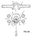
figures 6A à 6D sont des vues de face des différentes étapes de l'accrochage du cintre support sur la platine de fixation du dispositif conforme à l'invention.
- the
figure 1 is an exploded perspective view of the flat screen fixing device according to the invention, - the
figure 2 is an exploded sectional view of the mounting plate of the device according to the invention, - the
figure 3 is a sectional view of a detail of the mounting plate of the fastening device according to the invention, - the
figure 4 is a perspective view of the pawl forming the securing means of the support hanger on the mounting plate of the device according to the invention, - the
figure 5 is a top view of the fixing plate and the slide part in which is inserted the support hanger of the device according to the invention, - the
Figures 6A to 6D are front views of the various stages of attachment of the support hanger on the mounting plate of the device according to the invention.
On décrira ci-après, à titre d'exemple non limitatif, un dispositif de fixation d'un écran plat dit « slim » sur un mur ; toutefois, il est bien évident que le dispositif de fixation pourra être utilisé pour la fixation de tout type d'écran plat sur tout type de support vertical ou incliné sans pour autant sortir du cadre de l'invention.Hereinafter will be described by way of non-limiting example, a device for fixing a flat screen called "slim" on a wall; However, it is obvious that the fixing device can be used for fixing any type of flat screen on any type of vertical or inclined support without departing from the scope of the invention.
En référence à la
En référence aux
Par ailleurs, chaque rondelle excentrique 8 comporte une fente radiale 10 s'étendant sensiblement depuis le centre jusqu'à la collerette 9, ladite fente permettant le passage d'une vis de fixation non représentée sur les figures.Furthermore, each
Il va de soi que chaque rondelle excentrique 8 pourra comprendre plusieurs fentes radiales 10.It goes without saying that each
Accessoirement, la platine de fixation 1 comporte des capots obturateurs 11 circulaires venant coiffer les jours 6 et les rondelles excentriques 8. Lesdits capots obturateurs sont obtenus dans une matière plastique et sont maintenus en place par déformation élastique en prenant appui sur l'épaulement circulaire 7 et sur le bord périphérique de la collerette circulaire 9 de la rondelle excentrique 8.Incidentally, the mounting
Il est bien évident que la platine support 1 pourra présenter une forme quelconque et/ou être substituée par un cadre rectangulaire sans pour autant sortir du cadre de l'invention.It is obvious that the
Accessoirement, la platine support 1 comporte dans sa partie centrale un niveau à bulle 12 permettant de s'assurer de l'horizontalité lors de la fixation de la platine 1 sur le mur, un défaut d'horizontalité de la platine 1 entraînant ultérieurement un défaut d'horizontalité de l'écran.Incidentally, the
Ainsi, pour la fixation de la platine sur un mur, un utilisateur perce quatre trous dans le mur au moyen d'un gabarit, par exemple, non représenté sur les figures, et d'une perceuse, puis, après avoir introduit des chevilles appropriées dans lesdits trous, il place la platine 1 munie des rondelles excentriques 8 de telle manière que les jours circulaires 6 soient sensiblement au droit desdits trous. L'utilisateur fait ensuite tourner les rondelles excentriques 8 jusqu'à ce que, d'une part, les fentes 10 soient toutes au droit des trous et, d'autre part, que le niveau à bulle indique une parfaite horizontalité. L'utilisateur peut alors visser les vis à travers les fentes 10, puis il place les capots obturateurs 11 sur les rondelles excentriques 8 afin de les cacher.Thus, for fixing the plate on a wall, a user drills four holes in the wall by means of a template, for example, not shown in the figures, and a drill, then, after introducing appropriate dowels in said holes, he places the
Par ailleurs, en référence à la
Il va de soi que le dispositif pourra comporter d'autres tailles de cintre 3 en fonction des dimensions de l'écran à fixer.It goes without saying that the device may include other sizes of
L'un des bords de la fente 15 du cintre support 3 comporte une encoche 16, ladite encoche 16 étant positionnée à proximité de l'extrémité inférieure de la fente 15. Par ailleurs, chaque branche 13a,13b du cintre 3 comporte des trous 17 répartis le long de chaque branche 13a,13b à intervalles réguliers pour le passage de vis fixation de l'écran. De plus, le dispositif comporte des entretoises 18 destinées à être positionnées entre la face arrière de l'écran plat et les branches 13a,13b du cintre support 3. Accessoirement, le dispositif comporte des butées cylindriques, non représentées sur la
En référence aux
En référence aux
Il va de soi que le moyen de rappel 30 pourra consister dans tout moyen de rappel bien connu de l'Homme du Métier.It goes without saying that the return means 30 may consist in any recall means well known to those skilled in the art.
Enfin, le cliquet 25 comporte un cordon de commande 31 solidaire de la base du bras curviligne 28 afin de permettre le retrait du crochet 27 de l'encoche 16 de la fente 15 lorsqu'une traction sur le cordon 31 est exercée, l'autre extrémité du cordon 31 étant avantageusement solidaire d'un dévidoir 32.Finally, the
On expliquera maintenant le fonctionnement du dispositif de fixation conforme à l'invention à partir des
En référence à la
L'utilisateur descend alors l'écran de telle sorte que les bords de la fente 15 coulissent dans les glissières 21 jusqu'à ce que l'extrémité inférieure du bord de la fente 15 portant l'encoche 16 prenne appui sur le chemin de came 29 du crochet 27, en référence à la
En référence à la
Il va de soi que la platine support 1 pourra être utilisé indépendamment du cintre support 3 et des moyens de solidarisation 19 pour fixer un objet quelconque sur un support.It goes without saying that the
Enfin, il est bien évident que les exemples que l'on vient de donner ne sont que des illustrations particulières en aucun cas limitatives quant au domaine d'application de l'invention.Finally, it is obvious that the examples which have just been given are only particular illustrations in no way limiting as to the field of application of the invention.
Claims (15)
Applications Claiming Priority (2)
| Application Number | Priority Date | Filing Date | Title |
|---|---|---|---|
| FR1052241A FR2958005B1 (en) | 2010-03-26 | 2010-03-26 | FIXING DEVICE |
| FR1052240A FR2957993B1 (en) | 2010-03-26 | 2010-03-26 | FIXING DEVICE FOR FLAT SCREEN |
Publications (3)
| Publication Number | Publication Date |
|---|---|
| EP2369219A2 true EP2369219A2 (en) | 2011-09-28 |
| EP2369219A3 EP2369219A3 (en) | 2012-04-18 |
| EP2369219B1 EP2369219B1 (en) | 2013-08-28 |
Family
ID=44356170
Family Applications (1)
| Application Number | Title | Priority Date | Filing Date |
|---|---|---|---|
| EP11159894.2A Active EP2369219B1 (en) | 2010-03-26 | 2011-03-25 | Attachment device for a flat screen |
Country Status (1)
| Country | Link |
|---|---|
| EP (1) | EP2369219B1 (en) |
Cited By (5)
| Publication number | Priority date | Publication date | Assignee | Title |
|---|---|---|---|---|
| WO2013087406A1 (en) * | 2011-12-12 | 2013-06-20 | Barco N.V. | Support structure for an article, method of mounting the support structure, and support bracket |
| CN104455963A (en) * | 2014-10-30 | 2015-03-25 | 京东方科技集团股份有限公司 | Spliced screen stand |
| EP3220037A1 (en) | 2016-03-18 | 2017-09-20 | Erard | Support system for flat screen and method for operation |
| US11191178B2 (en) | 2019-01-24 | 2021-11-30 | Steelcase Inc. | Display support system and method for the use thereof |
| US11647834B2 (en) | 2020-07-23 | 2023-05-16 | Steelcase Inc. | Display support system and method for the use thereof |
Citations (3)
| Publication number | Priority date | Publication date | Assignee | Title |
|---|---|---|---|---|
| FR2872873A1 (en) | 2004-07-06 | 2006-01-13 | Erard Soc Par Actions Simplifi | Vertical indexing and inclining device for LCD and plasma type flat screen, has concave toothed sector that penetrates in tooth of convex semi circular toothed sector which is connected to metallic plate |
| US20070097619A1 (en) | 2005-10-31 | 2007-05-03 | David Quijano | Electronic device quick connect system |
| US20080192418A1 (en) | 2006-12-28 | 2008-08-14 | Bell'o International Corp. | Flat panel display mounting system |
Family Cites Families (4)
| Publication number | Priority date | Publication date | Assignee | Title |
|---|---|---|---|---|
| US6371424B1 (en) * | 1999-09-10 | 2002-04-16 | General Dynamics Canada Ltd. | Mounting an article upon a support |
| US6874744B2 (en) * | 2002-02-25 | 2005-04-05 | Wacom Co., Ltd. | Stand for supporting a display in multiple orientations and a display used in combination with said stand |
| EP1703195A1 (en) * | 2005-03-18 | 2006-09-20 | Market Link USA, Inc. | Video monitor mount |
| DE202005009471U1 (en) * | 2005-06-16 | 2005-10-13 | Hung, Chin-Jui, Wu-Chi Chen | Mounting arm for monitors comprises upright with clamp at bottom, inner arm being pivoted at top and linked to outer arm by toggle joint and outer arm carrying ball-and-socket joint, on to which connector for attaching monitor is fitted |
-
2011
- 2011-03-25 EP EP11159894.2A patent/EP2369219B1/en active Active
Patent Citations (3)
| Publication number | Priority date | Publication date | Assignee | Title |
|---|---|---|---|---|
| FR2872873A1 (en) | 2004-07-06 | 2006-01-13 | Erard Soc Par Actions Simplifi | Vertical indexing and inclining device for LCD and plasma type flat screen, has concave toothed sector that penetrates in tooth of convex semi circular toothed sector which is connected to metallic plate |
| US20070097619A1 (en) | 2005-10-31 | 2007-05-03 | David Quijano | Electronic device quick connect system |
| US20080192418A1 (en) | 2006-12-28 | 2008-08-14 | Bell'o International Corp. | Flat panel display mounting system |
Cited By (10)
| Publication number | Priority date | Publication date | Assignee | Title |
|---|---|---|---|---|
| WO2013087406A1 (en) * | 2011-12-12 | 2013-06-20 | Barco N.V. | Support structure for an article, method of mounting the support structure, and support bracket |
| CN104040241A (en) * | 2011-12-12 | 2014-09-10 | 巴科股份有限公司 | Support Structure For An Article, Method Of Mounting The Support Structure, And Support Bracket |
| US9133979B2 (en) | 2011-12-12 | 2015-09-15 | Barco N.V. | Support structure for an article, method of mounting the support structure, and support bracket |
| US9546757B2 (en) | 2011-12-12 | 2017-01-17 | Barco Nv | Support structure for an article, method of mounting the support structure, and support bracket |
| CN104040241B (en) * | 2011-12-12 | 2017-07-18 | 巴科股份有限公司 | The supporting structure of object, the installation method of supporting structure and frame support bracket |
| CN104455963A (en) * | 2014-10-30 | 2015-03-25 | 京东方科技集团股份有限公司 | Spliced screen stand |
| EP3220037A1 (en) | 2016-03-18 | 2017-09-20 | Erard | Support system for flat screen and method for operation |
| US11191178B2 (en) | 2019-01-24 | 2021-11-30 | Steelcase Inc. | Display support system and method for the use thereof |
| US11903158B2 (en) | 2019-01-24 | 2024-02-13 | Steelcase Inc. | Display support system and method for the use thereof |
| US11647834B2 (en) | 2020-07-23 | 2023-05-16 | Steelcase Inc. | Display support system and method for the use thereof |
Also Published As
| Publication number | Publication date |
|---|---|
| EP2369219B1 (en) | 2013-08-28 |
| EP2369219A3 (en) | 2012-04-18 |
Similar Documents
| Publication | Publication Date | Title |
|---|---|---|
| EP2369219B1 (en) | Attachment device for a flat screen | |
| CA2202205C (en) | Carriage for sliding door, window, etc | |
| EP3264945B1 (en) | Modular storage facility | |
| FR2965527A1 (en) | Holder for fastening portable electronic device, such as cell phone or electronic organizer, particularly in dashboard of motor vehicle, has fixed base for receiving electronic device, where fixed base has upper part and lower part | |
| EP0707681B1 (en) | Sliding panel and corner bracket for same | |
| CA1266698A (en) | Observation platform and support | |
| EP2669566B1 (en) | Screen support | |
| BE1007921A3 (en) | Device for ceiling formwork. | |
| FR2957993A1 (en) | Device for fixing plasma or LCD type flat slim screen of e.g. TV on wall, has curved arm supported on bottom edge of support arch when hook is withdrawn from notch to allow removal of arch from securing unit of support plate | |
| FR2510349A1 (en) | Flower box for mounting on wall - uses externally toothed L=shaped bar threaded through toothed opening in raised box flange | |
| EP3555975B1 (en) | System comprising a carrier rail and a plate configured to be attached to a support and to immobilise the rail arranged standing under the support | |
| FR2630311A1 (en) | QUICK LOCKING DEVICE FOR EXTENDABLE DRAWER SLIDES | |
| EP3558062B1 (en) | Metal tablet for equipping a stand display, such as a gondole | |
| FR2956257A1 (en) | Unit for pre-assembling frame of electrical appliance on lengthened electric chute, has mounting units arranged to hook and to slide along longitudinal axis of lengthened electric chute | |
| WO2007083005A1 (en) | Fixing system for hanging bar for kitchen utensils | |
| FR3080109A1 (en) | DECAPSULATOR DEVICE - RECAPSULATOR | |
| FR2958005A1 (en) | Device for fixing plasma or LCD type flat slim screen of e.g. TV on wall, has curved arm supported on bottom edge of support arch when hook is withdrawn from notch to allow removal of arch from securing unit of support plate | |
| EP1714596B1 (en) | Dispensing apparatus for powder material | |
| WO2013131714A1 (en) | Device for attaching a metal cross-member to a vehicle seat back | |
| FR2982134A1 (en) | TOUCH TABLET SUPPORT | |
| EP2362103B1 (en) | Clamp for positioning and locking supporting feet on the frame of a fishing seat-box | |
| EP3246280B1 (en) | Retaining device for a winder | |
| FR3073377A1 (en) | DEVICE FOR THE REMOVABLE FASTENING OF A SHELF | |
| EP3824153A1 (en) | Guardrail having an adjustable configuration, and construction elements of said guardrail | |
| FR3007055A1 (en) | DEVICE FOR TEMPORARILY CLOSING AN ELEMENT OPENING ON A SUPPORT ELEMENT |
Legal Events
| Date | Code | Title | Description |
|---|---|---|---|
| PUAI | Public reference made under article 153(3) epc to a published international application that has entered the european phase |
Free format text: ORIGINAL CODE: 0009012 |
|
| AK | Designated contracting states |
Kind code of ref document: A2 Designated state(s): AL AT BE BG CH CY CZ DE DK EE ES FI FR GB GR HR HU IE IS IT LI LT LU LV MC MK MT NL NO PL PT RO RS SE SI SK SM TR |
|
| AX | Request for extension of the european patent |
Extension state: BA ME |
|
| PUAL | Search report despatched |
Free format text: ORIGINAL CODE: 0009013 |
|
| AK | Designated contracting states |
Kind code of ref document: A3 Designated state(s): AL AT BE BG CH CY CZ DE DK EE ES FI FR GB GR HR HU IE IS IT LI LT LU LV MC MK MT NL NO PL PT RO RS SE SI SK SM TR |
|
| AX | Request for extension of the european patent |
Extension state: BA ME |
|
| RIC1 | Information provided on ipc code assigned before grant |
Ipc: F16M 11/04 20060101AFI20120309BHEP |
|
| 17P | Request for examination filed |
Effective date: 20120906 |
|
| GRAP | Despatch of communication of intention to grant a patent |
Free format text: ORIGINAL CODE: EPIDOSNIGR1 |
|
| GRAS | Grant fee paid |
Free format text: ORIGINAL CODE: EPIDOSNIGR3 |
|
| GRAP | Despatch of communication of intention to grant a patent |
Free format text: ORIGINAL CODE: EPIDOSNIGR1 |
|
| GRAA | (expected) grant |
Free format text: ORIGINAL CODE: 0009210 |
|
| INTG | Intention to grant announced |
Effective date: 20130701 |
|
| AK | Designated contracting states |
Kind code of ref document: B1 Designated state(s): AL AT BE BG CH CY CZ DE DK EE ES FI FR GB GR HR HU IE IS IT LI LT LU LV MC MK MT NL NO PL PT RO RS SE SI SK SM TR |
|
| REG | Reference to a national code |
Ref country code: GB Ref legal event code: FG4D Free format text: NOT ENGLISH |
|
| REG | Reference to a national code |
Ref country code: CH Ref legal event code: EP |
|
| REG | Reference to a national code |
Ref country code: AT Ref legal event code: REF Ref document number: 629561 Country of ref document: AT Kind code of ref document: T Effective date: 20130915 |
|
| REG | Reference to a national code |
Ref country code: IE Ref legal event code: FG4D Free format text: LANGUAGE OF EP DOCUMENT: FRENCH |
|
| REG | Reference to a national code |
Ref country code: DE Ref legal event code: R096 Ref document number: 602011002777 Country of ref document: DE Effective date: 20131024 |
|
| REG | Reference to a national code |
Ref country code: AT Ref legal event code: MK05 Ref document number: 629561 Country of ref document: AT Kind code of ref document: T Effective date: 20130828 |
|
| REG | Reference to a national code |
Ref country code: LT Ref legal event code: MG4D |
|
| REG | Reference to a national code |
Ref country code: NL Ref legal event code: VDEP Effective date: 20130828 |
|
| PG25 | Lapsed in a contracting state [announced via postgrant information from national office to epo] |
Ref country code: HR Free format text: LAPSE BECAUSE OF FAILURE TO SUBMIT A TRANSLATION OF THE DESCRIPTION OR TO PAY THE FEE WITHIN THE PRESCRIBED TIME-LIMIT Effective date: 20130828 Ref country code: SE Free format text: LAPSE BECAUSE OF FAILURE TO SUBMIT A TRANSLATION OF THE DESCRIPTION OR TO PAY THE FEE WITHIN THE PRESCRIBED TIME-LIMIT Effective date: 20130828 Ref country code: CY Free format text: LAPSE BECAUSE OF FAILURE TO SUBMIT A TRANSLATION OF THE DESCRIPTION OR TO PAY THE FEE WITHIN THE PRESCRIBED TIME-LIMIT Effective date: 20130619 Ref country code: AT Free format text: LAPSE BECAUSE OF FAILURE TO SUBMIT A TRANSLATION OF THE DESCRIPTION OR TO PAY THE FEE WITHIN THE PRESCRIBED TIME-LIMIT Effective date: 20130828 Ref country code: LT Free format text: LAPSE BECAUSE OF FAILURE TO SUBMIT A TRANSLATION OF THE DESCRIPTION OR TO PAY THE FEE WITHIN THE PRESCRIBED TIME-LIMIT Effective date: 20130828 Ref country code: NO Free format text: LAPSE BECAUSE OF FAILURE TO SUBMIT A TRANSLATION OF THE DESCRIPTION OR TO PAY THE FEE WITHIN THE PRESCRIBED TIME-LIMIT Effective date: 20131128 Ref country code: PT Free format text: LAPSE BECAUSE OF FAILURE TO SUBMIT A TRANSLATION OF THE DESCRIPTION OR TO PAY THE FEE WITHIN THE PRESCRIBED TIME-LIMIT Effective date: 20131230 Ref country code: IS Free format text: LAPSE BECAUSE OF FAILURE TO SUBMIT A TRANSLATION OF THE DESCRIPTION OR TO PAY THE FEE WITHIN THE PRESCRIBED TIME-LIMIT Effective date: 20131228 |
|
| REG | Reference to a national code |
Ref country code: NL Ref legal event code: VDEP Effective date: 20130828 |
|
| PG25 | Lapsed in a contracting state [announced via postgrant information from national office to epo] |
Ref country code: PL Free format text: LAPSE BECAUSE OF FAILURE TO SUBMIT A TRANSLATION OF THE DESCRIPTION OR TO PAY THE FEE WITHIN THE PRESCRIBED TIME-LIMIT Effective date: 20130828 Ref country code: GR Free format text: LAPSE BECAUSE OF FAILURE TO SUBMIT A TRANSLATION OF THE DESCRIPTION OR TO PAY THE FEE WITHIN THE PRESCRIBED TIME-LIMIT Effective date: 20131129 Ref country code: LV Free format text: LAPSE BECAUSE OF FAILURE TO SUBMIT A TRANSLATION OF THE DESCRIPTION OR TO PAY THE FEE WITHIN THE PRESCRIBED TIME-LIMIT Effective date: 20130828 Ref country code: SI Free format text: LAPSE BECAUSE OF FAILURE TO SUBMIT A TRANSLATION OF THE DESCRIPTION OR TO PAY THE FEE WITHIN THE PRESCRIBED TIME-LIMIT Effective date: 20130828 Ref country code: FI Free format text: LAPSE BECAUSE OF FAILURE TO SUBMIT A TRANSLATION OF THE DESCRIPTION OR TO PAY THE FEE WITHIN THE PRESCRIBED TIME-LIMIT Effective date: 20130828 |
|
| PG25 | Lapsed in a contracting state [announced via postgrant information from national office to epo] |
Ref country code: CY Free format text: LAPSE BECAUSE OF FAILURE TO SUBMIT A TRANSLATION OF THE DESCRIPTION OR TO PAY THE FEE WITHIN THE PRESCRIBED TIME-LIMIT Effective date: 20130828 |
|
| PG25 | Lapsed in a contracting state [announced via postgrant information from national office to epo] |
Ref country code: CZ Free format text: LAPSE BECAUSE OF FAILURE TO SUBMIT A TRANSLATION OF THE DESCRIPTION OR TO PAY THE FEE WITHIN THE PRESCRIBED TIME-LIMIT Effective date: 20130828 Ref country code: NL Free format text: LAPSE BECAUSE OF FAILURE TO SUBMIT A TRANSLATION OF THE DESCRIPTION OR TO PAY THE FEE WITHIN THE PRESCRIBED TIME-LIMIT Effective date: 20130828 Ref country code: EE Free format text: LAPSE BECAUSE OF FAILURE TO SUBMIT A TRANSLATION OF THE DESCRIPTION OR TO PAY THE FEE WITHIN THE PRESCRIBED TIME-LIMIT Effective date: 20130828 Ref country code: RO Free format text: LAPSE BECAUSE OF FAILURE TO SUBMIT A TRANSLATION OF THE DESCRIPTION OR TO PAY THE FEE WITHIN THE PRESCRIBED TIME-LIMIT Effective date: 20130828 Ref country code: DK Free format text: LAPSE BECAUSE OF FAILURE TO SUBMIT A TRANSLATION OF THE DESCRIPTION OR TO PAY THE FEE WITHIN THE PRESCRIBED TIME-LIMIT Effective date: 20130828 Ref country code: SK Free format text: LAPSE BECAUSE OF FAILURE TO SUBMIT A TRANSLATION OF THE DESCRIPTION OR TO PAY THE FEE WITHIN THE PRESCRIBED TIME-LIMIT Effective date: 20130828 |
|
| PG25 | Lapsed in a contracting state [announced via postgrant information from national office to epo] |
Ref country code: ES Free format text: LAPSE BECAUSE OF FAILURE TO SUBMIT A TRANSLATION OF THE DESCRIPTION OR TO PAY THE FEE WITHIN THE PRESCRIBED TIME-LIMIT Effective date: 20130828 |
|
| REG | Reference to a national code |
Ref country code: DE Ref legal event code: R097 Ref document number: 602011002777 Country of ref document: DE |
|
| PLBE | No opposition filed within time limit |
Free format text: ORIGINAL CODE: 0009261 |
|
| STAA | Information on the status of an ep patent application or granted ep patent |
Free format text: STATUS: NO OPPOSITION FILED WITHIN TIME LIMIT |
|
| 26N | No opposition filed |
Effective date: 20140530 |
|
| REG | Reference to a national code |
Ref country code: DE Ref legal event code: R097 Ref document number: 602011002777 Country of ref document: DE Effective date: 20140530 |
|
| PG25 | Lapsed in a contracting state [announced via postgrant information from national office to epo] |
Ref country code: LU Free format text: LAPSE BECAUSE OF FAILURE TO SUBMIT A TRANSLATION OF THE DESCRIPTION OR TO PAY THE FEE WITHIN THE PRESCRIBED TIME-LIMIT Effective date: 20140325 |
|
| REG | Reference to a national code |
Ref country code: IE Ref legal event code: MM4A |
|
| PG25 | Lapsed in a contracting state [announced via postgrant information from national office to epo] |
Ref country code: IE Free format text: LAPSE BECAUSE OF NON-PAYMENT OF DUE FEES Effective date: 20140325 |
|
| PG25 | Lapsed in a contracting state [announced via postgrant information from national office to epo] |
Ref country code: MT Free format text: LAPSE BECAUSE OF FAILURE TO SUBMIT A TRANSLATION OF THE DESCRIPTION OR TO PAY THE FEE WITHIN THE PRESCRIBED TIME-LIMIT Effective date: 20130828 |
|
| REG | Reference to a national code |
Ref country code: FR Ref legal event code: PLFP Year of fee payment: 6 |
|
| PG25 | Lapsed in a contracting state [announced via postgrant information from national office to epo] |
Ref country code: SM Free format text: LAPSE BECAUSE OF FAILURE TO SUBMIT A TRANSLATION OF THE DESCRIPTION OR TO PAY THE FEE WITHIN THE PRESCRIBED TIME-LIMIT Effective date: 20130828 |
|
| PG25 | Lapsed in a contracting state [announced via postgrant information from national office to epo] |
Ref country code: MC Free format text: LAPSE BECAUSE OF FAILURE TO SUBMIT A TRANSLATION OF THE DESCRIPTION OR TO PAY THE FEE WITHIN THE PRESCRIBED TIME-LIMIT Effective date: 20130828 |
|
| PG25 | Lapsed in a contracting state [announced via postgrant information from national office to epo] |
Ref country code: RS Free format text: LAPSE BECAUSE OF FAILURE TO SUBMIT A TRANSLATION OF THE DESCRIPTION OR TO PAY THE FEE WITHIN THE PRESCRIBED TIME-LIMIT Effective date: 20130828 Ref country code: BG Free format text: LAPSE BECAUSE OF FAILURE TO SUBMIT A TRANSLATION OF THE DESCRIPTION OR TO PAY THE FEE WITHIN THE PRESCRIBED TIME-LIMIT Effective date: 20130828 |
|
| PG25 | Lapsed in a contracting state [announced via postgrant information from national office to epo] |
Ref country code: HU Free format text: LAPSE BECAUSE OF FAILURE TO SUBMIT A TRANSLATION OF THE DESCRIPTION OR TO PAY THE FEE WITHIN THE PRESCRIBED TIME-LIMIT; INVALID AB INITIO Effective date: 20110325 Ref country code: TR Free format text: LAPSE BECAUSE OF FAILURE TO SUBMIT A TRANSLATION OF THE DESCRIPTION OR TO PAY THE FEE WITHIN THE PRESCRIBED TIME-LIMIT Effective date: 20130828 |
|
| REG | Reference to a national code |
Ref country code: FR Ref legal event code: PLFP Year of fee payment: 7 |
|
| REG | Reference to a national code |
Ref country code: FR Ref legal event code: PLFP Year of fee payment: 8 |
|
| PG25 | Lapsed in a contracting state [announced via postgrant information from national office to epo] |
Ref country code: MK Free format text: LAPSE BECAUSE OF FAILURE TO SUBMIT A TRANSLATION OF THE DESCRIPTION OR TO PAY THE FEE WITHIN THE PRESCRIBED TIME-LIMIT Effective date: 20130828 |
|
| PG25 | Lapsed in a contracting state [announced via postgrant information from national office to epo] |
Ref country code: AL Free format text: LAPSE BECAUSE OF FAILURE TO SUBMIT A TRANSLATION OF THE DESCRIPTION OR TO PAY THE FEE WITHIN THE PRESCRIBED TIME-LIMIT Effective date: 20130828 |
|
| PGFP | Annual fee paid to national office [announced via postgrant information from national office to epo] |
Ref country code: CH Payment date: 20210322 Year of fee payment: 11 |
|
| PGFP | Annual fee paid to national office [announced via postgrant information from national office to epo] |
Ref country code: GB Payment date: 20220316 Year of fee payment: 12 |
|
| PGFP | Annual fee paid to national office [announced via postgrant information from national office to epo] |
Ref country code: IT Payment date: 20220308 Year of fee payment: 12 Ref country code: BE Payment date: 20220316 Year of fee payment: 12 |
|
| REG | Reference to a national code |
Ref country code: CH Ref legal event code: PL |
|
| PG25 | Lapsed in a contracting state [announced via postgrant information from national office to epo] |
Ref country code: LI Free format text: LAPSE BECAUSE OF NON-PAYMENT OF DUE FEES Effective date: 20220331 Ref country code: CH Free format text: LAPSE BECAUSE OF NON-PAYMENT OF DUE FEES Effective date: 20220331 |
|
| PGFP | Annual fee paid to national office [announced via postgrant information from national office to epo] |
Ref country code: FR Payment date: 20230327 Year of fee payment: 13 |
|
| PGFP | Annual fee paid to national office [announced via postgrant information from national office to epo] |
Ref country code: DE Payment date: 20230307 Year of fee payment: 13 |
|
| P01 | Opt-out of the competence of the unified patent court (upc) registered |
Effective date: 20230527 |
|
| GBPC | Gb: european patent ceased through non-payment of renewal fee |
Effective date: 20230325 |
|
| REG | Reference to a national code |
Ref country code: BE Ref legal event code: MM Effective date: 20230331 |
|
| PG25 | Lapsed in a contracting state [announced via postgrant information from national office to epo] |
Ref country code: GB Free format text: LAPSE BECAUSE OF NON-PAYMENT OF DUE FEES Effective date: 20230325 |
|
| PG25 | Lapsed in a contracting state [announced via postgrant information from national office to epo] |
Ref country code: GB Free format text: LAPSE BECAUSE OF NON-PAYMENT OF DUE FEES Effective date: 20230325 |
|
| PG25 | Lapsed in a contracting state [announced via postgrant information from national office to epo] |
Ref country code: BE Free format text: LAPSE BECAUSE OF NON-PAYMENT OF DUE FEES Effective date: 20230331 |