EP2369078A2 - Isolationsmaterial - Google Patents
Isolationsmaterial Download PDFInfo
- Publication number
- EP2369078A2 EP2369078A2 EP11000896A EP11000896A EP2369078A2 EP 2369078 A2 EP2369078 A2 EP 2369078A2 EP 11000896 A EP11000896 A EP 11000896A EP 11000896 A EP11000896 A EP 11000896A EP 2369078 A2 EP2369078 A2 EP 2369078A2
- Authority
- EP
- European Patent Office
- Prior art keywords
- insulating material
- insulation
- insulation material
- zone
- fibers
- Prior art date
- Legal status (The legal status is an assumption and is not a legal conclusion. Google has not performed a legal analysis and makes no representation as to the accuracy of the status listed.)
- Granted
Links
Images


Classifications
-
- E—FIXED CONSTRUCTIONS
- E04—BUILDING
- E04B—GENERAL BUILDING CONSTRUCTIONS; WALLS, e.g. PARTITIONS; ROOFS; FLOORS; CEILINGS; INSULATION OR OTHER PROTECTION OF BUILDINGS
- E04B1/00—Constructions in general; Structures which are not restricted either to walls, e.g. partitions, or floors or ceilings or roofs
- E04B1/62—Insulation or other protection; Elements or use of specified material therefor
- E04B1/74—Heat, sound or noise insulation, absorption, or reflection; Other building methods affording favourable thermal or acoustical conditions, e.g. accumulating of heat within walls
- E04B1/76—Heat, sound or noise insulation, absorption, or reflection; Other building methods affording favourable thermal or acoustical conditions, e.g. accumulating of heat within walls specifically with respect to heat only
- E04B1/78—Heat insulating elements
- E04B1/80—Heat insulating elements slab-shaped
-
- B—PERFORMING OPERATIONS; TRANSPORTING
- B60—VEHICLES IN GENERAL
- B60P—VEHICLES ADAPTED FOR LOAD TRANSPORTATION OR TO TRANSPORT, TO CARRY, OR TO COMPRISE SPECIAL LOADS OR OBJECTS
- B60P3/00—Vehicles adapted to transport, to carry or to comprise special loads or objects
- B60P3/06—Vehicles adapted to transport, to carry or to comprise special loads or objects for carrying vehicles
- B60P3/07—Vehicles adapted to transport, to carry or to comprise special loads or objects for carrying vehicles for carrying road vehicles
- B60P3/073—Vehicle retainers
- B60P3/075—Vehicle retainers for wheels, hubs, or axle shafts
- B60P3/077—Wheel cradles, chocks, or wells
-
- E—FIXED CONSTRUCTIONS
- E04—BUILDING
- E04B—GENERAL BUILDING CONSTRUCTIONS; WALLS, e.g. PARTITIONS; ROOFS; FLOORS; CEILINGS; INSULATION OR OTHER PROTECTION OF BUILDINGS
- E04B1/00—Constructions in general; Structures which are not restricted either to walls, e.g. partitions, or floors or ceilings or roofs
- E04B1/62—Insulation or other protection; Elements or use of specified material therefor
- E04B1/74—Heat, sound or noise insulation, absorption, or reflection; Other building methods affording favourable thermal or acoustical conditions, e.g. accumulating of heat within walls
- E04B1/82—Heat, sound or noise insulation, absorption, or reflection; Other building methods affording favourable thermal or acoustical conditions, e.g. accumulating of heat within walls specifically with respect to sound only
- E04B1/84—Sound-absorbing elements
- E04B1/86—Sound-absorbing elements slab-shaped
-
- E—FIXED CONSTRUCTIONS
- E04—BUILDING
- E04B—GENERAL BUILDING CONSTRUCTIONS; WALLS, e.g. PARTITIONS; ROOFS; FLOORS; CEILINGS; INSULATION OR OTHER PROTECTION OF BUILDINGS
- E04B1/00—Constructions in general; Structures which are not restricted either to walls, e.g. partitions, or floors or ceilings or roofs
- E04B1/62—Insulation or other protection; Elements or use of specified material therefor
- E04B1/74—Heat, sound or noise insulation, absorption, or reflection; Other building methods affording favourable thermal or acoustical conditions, e.g. accumulating of heat within walls
- E04B1/88—Insulating elements for both heat and sound
- E04B1/90—Insulating elements for both heat and sound slab-shaped
-
- E—FIXED CONSTRUCTIONS
- E04—BUILDING
- E04D—ROOF COVERINGS; SKY-LIGHTS; GUTTERS; ROOF-WORKING TOOLS
- E04D13/00—Special arrangements or devices in connection with roof coverings; Protection against birds; Roof drainage ; Sky-lights
- E04D13/16—Insulating devices or arrangements in so far as the roof covering is concerned, e.g. characterised by the material or composition of the roof insulating material or its integration in the roof structure
- E04D13/1606—Insulation of the roof covering characterised by its integration in the roof structure
- E04D13/1612—Insulation of the roof covering characterised by its integration in the roof structure the roof structure comprising a supporting framework of roof purlins or rafters
-
- F—MECHANICAL ENGINEERING; LIGHTING; HEATING; WEAPONS; BLASTING
- F16—ENGINEERING ELEMENTS AND UNITS; GENERAL MEASURES FOR PRODUCING AND MAINTAINING EFFECTIVE FUNCTIONING OF MACHINES OR INSTALLATIONS; THERMAL INSULATION IN GENERAL
- F16L—PIPES; JOINTS OR FITTINGS FOR PIPES; SUPPORTS FOR PIPES, CABLES OR PROTECTIVE TUBING; MEANS FOR THERMAL INSULATION IN GENERAL
- F16L59/00—Thermal insulation in general
- F16L59/02—Shape or form of insulating materials, with or without coverings integral with the insulating materials
- F16L59/029—Shape or form of insulating materials, with or without coverings integral with the insulating materials layered
Definitions
- the invention relates to an insulating material which is used in the thermal and / or acoustic insulation of buildings but also in heating or cooling systems.
- a stiffness of the insulating materials used is required. This is needed to clamp, for example, insulating mats or rolls in the roof insulation between rafters.
- Insulation materials made of soft or rigid foams while easy to assemble, are too stiff to adapt to contours, especially in the area of roof insulation or in boiler construction. To adjust for bumps, material must be removed or cut out. This requires additional expenditure on manual work during installation or in preparation.
- insulating materials are, for example, from DE 19512787 or even the WO 2008/012680 known.
- the insulation materials have a good continuity and can therefore, because easy to clamp, just in the area of roof insulation / Eisensparrendämmung easy to install.
- a disadvantage of the above-described insulating materials is due to the homogeneous structure uniform stiffness of the material. If such materials are used, for example, in old building renovation, it often happens that the surface to be insulated unevenness. from the plane level has excellent locations or different thicknesses. If you now put the insulation on, arise due to the material stiffness between the insulating material and the surface to be insulated so-called fireplaces, in which air and therefore also circulates cold. The desired insulation effect is interrupted. The same applies to the insulation of boilers and pipes in heating or cooling systems. If you want to isolate a curved surface with the state of the art insulation, arise over the circumference at several places fold creases and thus again vacancies between the wall and insulation. In order to avoid this excess material is then removed or cut out, but this means increased manual effort during processing with the risk that improper work, i. To large erosion or cut, the chimneys are more pronounced.
- insulating materials are rigid materials in the x, y and z directions.
- this property is a hindrance.
- An inventively executed insulating material as in FIG. 1 shown in this case has an upper side (2) and a lower side (3). Seen above the thickness (4), the insulating material (1) has one of the upper side (2) facing High density zone (5) and one of the bottom (3) facing low density zone (6).
- the insulating material (1) is characterized by a pronounced two-sidedness with respect to the indentation hardness of the upper side (2) and the underside (3).
- the term "indentation hardness” refers to that force which opposes the insulating material of a pressure fin when this pressure fin penetrates into the insulating material by 20%.
- FIG. 4 shows a test setup suitable for determining the indentation hardness. This consists of a test plate (14) on which the specimen (15) is located. A load cell (12) with a measuring range of 0-100N and, in turn, a pressure fin (13) are attached to a movable crossmember (11)
- the pressure fin has a width of 50mm, a thickness of 10mm and a height of 35mm.
- the edge, which penetrates the insulation during the test, is rounded in a radius of 5mm.
- the indicator connected to the load cell is set to zero.
- the truss is then driven at a speed of 100mm / min in the direction of the insulating material, so that the pressure fin penetrates into the insulating material.
- the initial thickness D0 of the insulating material is determined.
- the pressure fin then continues to penetrate the insulating material until a distance of 0.4 * D0 has been traveled.
- the force applied to the load cell at this time is read off. This force is called indentation hardness in Newton (N) in the context of the present invention.
- the indentation hardness is expediently determined by means of universal testing machines from Zwick, Ulm, type 1425 on the upper side (2) and on the underside (3) of an insulating material determined.
- the value of 20% compression was determined based on conventional dimensions of battens or cable channels, as can be found again and again at the installation locations. Depending on the design of the insulating material according to the invention in terms of thickness, this represents an intrusion of Druckfinne between 4 and 60mm.
- FIGS. 2 and 3 should clarify this.
- a wall (8) is shown, from which protrudes a projection (9), for example a cable duct, a pipe, a batten or the like.
- FIG. 2 the wall (8) is covered with an insulating material (7), which corresponds to the prior art Due to the rigidity of the material and thus high Eindgurhärte a large part of the surface of the insulating material is deformed, so that the already mentioned cold bridges in the form of chimneys (10) can form left and right of the projection (9).
- FIG. 3 shows the same installation situation, wherein the insulation was carried out with an inventively designed insulating material (1).
- the underside (3) of the insulating material (1) according to the invention has a significantly lower indentation hardness compared to the upper side (2), so that the underside (3) of the insulating material (1) fits tightly around the projection (9) and therefore prevents chimney formation.
- FIG. 5 shows this again for a use case of strongly curved surfaces. Again, the rigidity of the prior art results in poor matching to the curved surface of the wall (8). There are fireplaces (9).
- An insulating material (1) according to the invention has an indentation hardness in the low-density zone (6) which is at most 0.5 times the indentation hardness of the high-density zone (5).
- starting materials for the production of an insulating material according to the invention all materials can be used by means of which a difference in Eind Weghärten can be displayed. Suitable examples are foams or nonwovens.
- Characteristic of insulating materials (1) according to the invention is the difference in the indentation hardness of the upper side (2) to the underside (3).
- melt fibers in the context of the present invention are fibers that melt by application of heat, in the molten state with the matrix fibers form a compound, so that the nonwoven after cooling is solidified.
- Commercially available, homogeneously or even bi-component melt fibers are suitable for this, the melting point of the fusible component preferably being at least 20 ° C. below that of the matrix fiber, if these are thermoplastic.
- Suitable matrix fibers are all fiber types available as staple fibers, that is to say natural fibers such as hemp or flax, but also synthetic fibers produced from natural or synthetic polymers such as, for example, polyethylene terephthalate or polylactides. Commercially available polyethylene terephthalate fibers are preferably used.
- the zone of high density (5) is equipped so that it occupies a maximum of 40% of the total thickness (4).
- the basis weight of the high-density zone (5) should be chosen so that it does not exceed 50% of the total surface weight.
- the proportion of melt fibers within the high density zone (5) is preferably 50% or higher.
- the melt fiber content in the low density zone (6) is preferably set at 30% or lower.
- fibers of a low titer ie less than 6.7 dtex, preferably less than 4.4 dtex.
- an insulating material according to the invention made of nonwoven fabric can be done for example by means of the carding process.
- the basic technique can be found in the book “ Nonwovens ", published by Wiley-Verlag, 2000 , are taken.
- the zones of high density (5) and low density zone (6) are formed by means of carding and subsequent nonwoven laying devices.
- the basis weight and thickness ranges to be selected for an inventive insulating material are based on the later fields of application.
- thicknesses (4) of between 80 and 300 mm are typical for basis weights of 1300 to 4000 g / m2.
- the zone of low density (6) occupies at least 60% of the thickness (4) of the insulating material (1) according to the invention. This means that at preferred thicknesses of 120 to 160mm, unevennesses of height up to 50mm are covered without problems, without causing chimney formation or unevenness on top (2), which is generally the show side.
- the unevenness to be covered are generally smaller, so that even at thicknesses of 20 to 80mm sufficient coverage is already given.
- the thickness is determined according to WSP 120.6 (05) at a preload of 0.02kPa, the basis weight according to WSP 130.1 (05).
- a first fiber blend consisting of 30 weight percent PET matrix fibers in the titer 1.7dtex, 20 weight percent PET matrix fibers in the titer 3.3dtex and 50 weight percent PET / co-PET bicomponent melt fiber of the Ker / shell type in the titer 4.4 dtex, produced.
- This first fiber mixture is processed by a first carding machine to a first batt, which is continuously fed to a first laying device.
- the first laying device for example a horizontal sleeper, now continuously screens individual layers on a collecting belt which is offset by 90 ° to the horizontal axis and moves continuously until the weight per unit area of the so-called formed, yet unconsolidated Faserflores 1500 g / sqm. These pile layers are to form the high-density zone (5) in the later insulating material.
- a second fiber blend consisting of 55 weight percent PET matrix fibers in 1.7 denier titer, 15 weight percent PET matrix fibers in titer 3.3 dtex, and 30 weight percent PET / co-PET bicomponent melt fibers of KerN jacket type in 4.4 ttex is prepared ,
- This second fiber mixture is processed by a second carding machine into a second fiber web, which is fed continuously to a second laying device.
- the second laying device now panels further pile layers, which form the subsequent zone of low density (6), on the collecting belt with the yarn pile thereon, produced by the first laying device and not yet consolidated, until a grammage of altogether 2900 g / m 2 results.
- the unbroken fibrous web thus produced is subsequently subjected to a heat treatment so that the fusible shell portion of the bicomponent melt fibers contained in the individual pile layers is activated and solidifies the nonwoven fabric.
- thermofusion This heat treatment, also called thermofusion, can be carried out by means of conventional flat belt dryers, as produced, for example, by Schott & Meissner and described in the book "Nonwovens".
- zones of high density (5) according to the invention are made up of the high melt fiber pile layers and the zones of low density (FIG. 6) form the pile layers with low melt fiber content.
- An insulating material (1) according to the invention produced in this way shows a significant difference in the indentation hardening of upper side (2) and lower side (3).
- FIGS. 7 and 8 illustrate this in comparison to the prior art again.
- An insulating material made according to the prior art has an indentation hardness due to the homogeneous structure, which has only a slight difference between top and bottom.
- FIG. 7 shows the force-compression curve, which was taken during the determination of Eindschreibhärte on a material according to the prior art.
- the curves for the Eindschreibhärte the top (16) and the bottom (17) run almost congruent to each other.
- an inventive insulating material (1) has a significant difference in Eindschreibhärten. Again FIG. 8 can be seen, there is a significant difference in Eindschreibhärte the top (16) to the bottom (17).
- the indentation hardness of the upper side (2) is 5.7 N and on the underside (3) 1.9 N, so it is 3 times higher.
- the indentation hardness on the upper side (2) is 2.5 times that of the underside (3).
- the indentation hardness of the underside (3) is therefore less than 5 N.
- the indentation hardness of the underside (3) is therefore less than 5 N.
- the bottom (3) of less than 3N proved suitable.
- the density of the insulating material is increased at the points of direct contact with a projection (9), such as a pipe or a rafter, and consequently also reduces the thermal conductivity.
- the insulating material due to the restoring force of the starting materials used, conforms to the contour of the projection (9).
- an insulating material (1) according to the invention thus fills up as much as possible and thus prevents chimney formation.
- an insulating material (1) according to the invention is additionally provided with a hydrophobic finish, it undergoes a significantly lower change in thermal conductivity when exposed to moisture than a hydrophilic insulating material (1) according to the invention.
- the material VP05019BA31 embodied according to the invention was additionally subjected to a hydrophobic finish, so that the material has hydrophobic properties seen on the top and bottom as well as over the entire thickness.
- Both insulators were irrigated with demineralized water for two hours. The samples were then stored for 24 h at a standard climate of 21 ° C / 65% relative humidity. Finally, the thermal conductivity was determined at different temperatures.
- the hydrophilic insulating material still contained up to 10% by weight of water, whereas the hydrophobically-finished insulating material had a water content of less than 0.1% by weight.
- a simple drop test is performed. A drop of demineralized water is applied to a surface of the insulating material. If the drop has not sunk into the structure after a period of at least 2 hours, the insulating material is said to be hydrophobic.
- the insulating material need not have hydrophobic properties over the entire thickness or on both sides (2) and (3), it is also possible to produce only the high-density zone (5) or the low-density zone (6) using hydrophobic starting materials , Also, only on one of the sides (2) or (3) located equipment prevents the ingress of moisture into the insulating material according to the invention (1).
- the choice of which side (2) or (3), or the high density zone (5) or the low density zone (6) should have hydrophobic properties depends on the particular end use, it must at least the side on which moisture penetration is most likely to be hydrophobic.
- the side (2) may also have a surface treatment, such as, for example, in a preferred embodiment, performed as thermal smoothing up to the complete skinning. This improves the mechanical stability, e.g. the accessibility and in addition an improvement of the water-repellent properties result.
- an insulating material (1) according to the invention flame-retardant agents such as expanded graphite and / or heat-storing additives such as carbon black may be added.
- flame-retardant agents such as expanded graphite and / or heat-storing additives such as carbon black
- heat-storing additives such as carbon black
- bactericidal / fungicidal substances is possible.
- These active ingredients can be mechanically embedded in the zones of high density (5) and low density (6), but it is also possible to embed the active ingredients directly in the starting materials, for example in the fibers.
- Insulating materials produced according to the invention can be produced both as plates and in the form of rolls, depending on the intended use. If the insulating material is assembled in the form of plates, grooves and springs can additionally be introduced on the outer sides of the plates, so that a positive, area-wide laying without interrupting the insulation effect is possible.
Landscapes
- Engineering & Computer Science (AREA)
- Physics & Mathematics (AREA)
- Architecture (AREA)
- Acoustics & Sound (AREA)
- Civil Engineering (AREA)
- Structural Engineering (AREA)
- Electromagnetism (AREA)
- General Engineering & Computer Science (AREA)
- Mechanical Engineering (AREA)
- Health & Medical Sciences (AREA)
- Public Health (AREA)
- Transportation (AREA)
- Building Environments (AREA)
- Thermal Insulation (AREA)
- Insulating Bodies (AREA)
Abstract
Description
- Die Erfindung betrifft ein Isolationsmaterial, welches in der thermischen und/oder akustischen Isolierung von Gebäuden aber auch in Heiz- bzw Kühlsystemen Verwendung findet.
- Bei der thermischen und / oder akustischen Isolierung ist, um die Verbaubarkeit zu gewährleisten, eine Steifigkeit der eingesetzten Isoliermaterialien gefordert. Diese wird benötigt um beispielsweise Isoliermatten oder -rollen im Bereich der Dachisolierung zwischen Sparren klemmen zu können.
- Aus dem Stand der Technik sind verschiedene Dämmsysteme bekannt.
- Dämmstoffe aus Weich- oder Hartschäumen, lassen sich zwar einfach konfektionieren, sind aber zu steif um sich Konturen, speziell im Bereich der Dachisolierung oder im Kesselbau anzupassen. Für die Anpassung an Unebenheiten muss Material abgetragen oder ausgeschnitten werden. Dies bedingt einen Mehraufwand an handwerklichen Tätigkeiten beim Einbau bzw in der Vorbereitung.
- Handelsüblich wird ein Großteil der Dämmungen aus Mineral- oder auch Glasfasern hergestellt. Diese sind als Platten oder Rollenware erhältlich. Aufgrund der Staubentwicklung beim Verbauen / Konfektionieren und der bekannten Hautirritationsproblematik sind sie nur bedingt einsetzbar.
- Aus Vliesstoffen hergestellte Isoliermaterialien, sind beispielsweise aus der
DE 19512787 oder auch derWO 2008/012680 bekannt. Die Isolationsmaterialien haben eine gute Stetigkeit und lassen sich daher, weil gut klemmbar, gerade im Bereich Dachisolierung / Zwischensparrendämmung einfach verbauen. - Nachteilig bei den vorbeschriebenen Isoliermaterialien ist die durch den homogenen Aufbau bedingte gleichmäßige Steifigkeit des Materials. Werden derartige Materialien beispielsweise in der Altbausanierung eingesetzt, kommt es häufig vor, dass die zu dämmende Fläche Unebenheiten d.h. aus der planen Ebene hervorragende Stellen oder unterschiedliche Dicken aufweist. Legt man nun das Isoliermaterial auf, ergeben sich aufgrund der Materialsteife zwischen dem Dämmmaterial und der zu dämmenden Fläche sogenannte Kamine, in welchen Luft und daher auch Kälte zirkuliert. Der gewünschte Dämmeffekt wird unterbrochen. Ähnliches gilt auch für die Isolierung von Kesseln und Rohren in Heiz- oder Kühlanlagen. Will man mit dem Stand der Technik entsprechenden Isoliermaterialien eine gekrümmte Oberfläche isolieren, ergeben sich über den Umfang an mehreren Stellen Knickfalten und dadurch wieder offene Stellen zwischen Wandung und Dämmung. Um dies zu vermeiden wird dann überschüssiges Material abgetragen oder ausgeschnitten, dies bedeutet aber erhöhten manuellen Aufwand bei der Verarbeitung mit der Gefahr, dass durch unsauberes Arbeiten, d.h. zu großem Abtrag oder Ausschnitt, die Kältekamine stärker ausgeprägt sind.
- Ausgehend vom Stand der Technik war es die Aufgabe der vorliegenden Erfindung, die beschriebenen Nachteile des Standes der Technik zu vermeiden.
- Die Aufgabe wird gemäß den Merkmalen der Ansprüche 1 bis 22 gelöst.
- Gemäß dem Stand der Technik sind bekannte Isoliermaterialien in x-, y- und auch in z-Richtung steife Materialien. Jedoch gerade in z-Richtung, d.h. über die Dicke eines Isoliermaterials, ist diese Eigenschaft hinderlich.
- Hier setzt die Erfindung an. Ein erfindungsgemäß ausgeführtes Isoliermaterial wie in
Figur 1 dargestellt, weist dabei eine Oberseite (2) und eine Unterseite (3) auf. Ober die Dicke (4) gesehen hat das Isoliermaterial (1) eine der Oberseite (2) zugewandte Zone hoher Dichte (5) und eine der Unterseite (3) zugewandte Zone geringer Dichte (6). - Das Isoliermaterial (1) zeichnet sich durch eine ausgeprägte Zweiseitigkeit in Bezug auf die Eindrückhärte der Oberseite (2) und der Unterseite (3) aus.
- Als Eindrückharte im Sinne der Erfindung wird diejenige Kraft bezeichnet, die das Isoliermaterial einer Druckfinne entgegensetzt, wenn diese Druckfinne um 20% in das Isoliermaterial eindringt.
-
Figur 4 zeigt einen zur Ermittlung der Eindrückhärte geeigneten Prüfaufbau. Dieser besteht aus einer Prüfplatte (14) auf welchem der Prüfling (15) liegt. An einer verfahrbaren Traverse (11) ist eine Kraftmessdose (12) mit einem Messbereich von 0-100N und an dieser wiederum eine Druckfinne (13) angebracht - Die Druckfinne hat eine Breite von 50mm, eine Dicke von 10mm und eine Höhe von 35mm. Die Kante, die beim Test in das Isoliermaterial eindringt, ist in einem Radius von 5mm abgerundet.
- Vor Beginn des Tests wird die mit der Kraftmessdose verbundene Anzeige auf null gesetzt. Die Traverse wird dann mit einer Geschwindigkeit von 100mm/min in Richtung des Isoliermaterials gefahren, sodass die Druckfinne in das Isoliermaterial eindringt.
- Sobald an der Kraftmessdose eine Kraft von 0,2N anliegt, wird die Ausgangsdicke D0 des Isoliermaterials bestimmt.
- Die Druckfinne dringt dann weiter in das Isoliermaterial ein, bis ein Weg von 0,4*D0 zurückgelegt wurde. Bei Erreichen eines Eindrückweges von 0,2*D0 wird die zu diesem Zeitpunkt an der Kraftmessdose anliegende Kraft abgelesen. Diese Kraft wird als Eindrückhärte in Newton (N) im Sinne der vorliegenden Erfindung bezeichnet.
- Zweckmäßig wird die Eindrückhärte mittels Universalprüfmaschinen der Fa. Zwick, Ulm, Typ 1425 an der Oberseite (2) und an der Unterseite (3) eines Isoliermaterials ermittelt. Der Wert von 20% Stauchung wurde aufgrund üblicher Maße von Lattungen oder Kabelkänale, ermittelt, wie sich immer wieder an den Einbauorten finden. Je nach Ausführung des erfindungsgemäßen Isoliermaterials bezüglich der Dicke stellt ein dies ein Eindringen der Druckfinne zwischen 4 und 60mm dar.
- Durch den erfindungsgemäßen Unterschied der Eindrückhärte von Oberseite (2) und Unterseite (3) ist es im Vergleich zum Stand der Technik möglich, beim Einbau aus ebenen Flächen herausragende Teile abzudichten und/oder durch die gute Zusammendrückbarkeit ein Abtragen von Material bei unterschiedlich tiefen Einbauorten zu vermeiden.
- Die
Figuren 2 und 3 sollen dies verdeutlichen. In beiden Figuren wird eine Wandung (8) gezeigt, aus welcher ein Vorsprung (9), beispielsweise ein Kabelkanal, eine Rohrleitung, eine Lattung oder ähnliches hervorragt. - In
Figur 2 wird die Wandung (8) mit einem Isolationsmaterial (7) abgedeckt, welches dem Stand der Technik entspricht Bedingt durch die Steifigkeit des Materials und dadurch hoher Eindrückhärte wird ein Großteil der Oberfläche des Isoliermaterials mit verformt, sodass sich die bereits erwähnten Kältebrücken in Form von Kaminen (10) links und rechts des Vorsprungs (9) bilden können. - Die
Figur 3 zeigt die gleiche Einbausituation, wobei die Isolierung mit einem erfindungsgemäß ausgeführten Isoliermaterial (1) durchgeführt wurde. - Die Unterseite (3) des erfindungsgemäßen Isoliermaterials (1) hat eine im Vergleich zur Oberseite (2) deutlich geringere Eindrückhärte, sodass sich die Unterseite (3) des Isoliermaterials (1) eng um den Vorsprung (9) legt und daher einer Kaminbildung vorbeugt.
- Die
Figur 5 zeigt dies nochmals für einen Anwendungsfall an stark gekrümmten Flächen. Auch hier ergibt sich beim Stand der Technik durch die Steifigkeit eine schlechte Anpassung an die gekrümmte Oberfläche der Wandung (8). Es entstehen Kamine (9). - Bei Verwendung eines erfindungsgemäßen Isoliermaterials (1) wie in
Figur 6 lassen sich diese vermeiden. - Ein erfindungsgemäß ausgeführtes Isoliermaterial (1) weist in der Zone geringer Dichte (6) eine Eindrückhärte auf, die maximal das 0,5-fache der Eindrückhärte der Zone hoher Dichte (5) beträgt.
- Als Ausgangsmaterialien für Herstellung eines erfindungsgemäßen Isoliermaterials können alle Materialien eingesetzt werden, mittels denen ein Unterschied in den Eindrückhärten darstellbar ist. Geeignet sind beispielsweise Schaumstoffe oder auch Vliesstoffe.
- Die nachstehenden Ausführungen beziehen sich auf aus Vliesstoffen aufgebaute, erfindungsgemäß ausgeführte isoliermaterialien ohne jedoch die Erfindung darauf zu beschränken.
- Kennzeichnend für erfindungsgemäße Isoliermaterialien (1) ist der Unterschied der Eindrückhärte der Oberseite (2) zur Unterseite (3).
- Bei der Verwendung von Stapelfaservliesen als Grundmaterialien gibt es verschiedene Möglichkeiten, diese Eigenschaft zu erreichen.
- Erreicht wird dies durch den Einsatz unterschiedlicher Fasermischungen, beispielsweise der Anteile an Schmelzfasern in den Zonen (5) und (6). In der Zone hoher Dichte (5) sind entsprechend höhere Anteile an Schmelzfasern im Vergleich zur Zone geringer Dichte (6) zu verwenden. Als günstig haben sich 30-80 Gewichtsprozent Schmelzfasern in der Zone hoher Dichte (5) und 10-50 Gewichtsprozent Schmeizfasern in der Zone geringer Dichte (6) erwiesen. Die jeweils auf 100 Gewichtsprozent fehlende Fasermenge wird mit Matrixfasern, d.h. handelsüblichen Stapelfasern auf synthetischer und/ oder natürlicher Basis, ergänzt.
- Schmelzfasern im Sinne der vorliegenden Erfindung sind Fasern die durch Beaufschlagung mit Hitze schmelzen, im schmelzflüssigen Zustand mit den Matrixfasern eine Verbindung eingehen, sodass das Vlies nach dem Abkühlen verfestigt ist. Geeignet sind dafür handelsübliche, homogen oder auch bikomponent aufgebaute Schmelzfasern, wobei der Schmelzpunkt der schmelzbaren Komponente bevorzugt mindestens 20°C unterhalb dessen der Matrixfaser, sofern diese thermoplastisch sind, zu wählen ist. Bevorzugt eingesetzt werden Polyester / CoPolyester Bikomponentenfasem als Schmelzfasern.
- Als Matrixfasern sind alle als Stapelfaser erhältlichen Fasertypen, das heißt Naturfasern wie Hanf oder Flachs, aber auch aus natürlichen oder synthetischen Polymeren wie beispielsweise Polyethylenterephthalat oder Polylactiden hergestellte Synthesefasern, einsetzbar. Bevorzugt kommen handelsübliche Polyethylenterephthalat-Fasern zum Einsatz.
- In einer besonders bevorzugten Ausführungsform wird innerhalb des Isoliermaterials (1) die Zone hoher Dichte (5) so ausgestattet, dass sie maximal 40% der Gesamtdicke (4) einnimmt. Das Flächengewicht der Zone hoher Dichte (5) ist dabei so zu wählen, dass es maximal 50% des Gesamtflächengewichts ausmacht. Auch ist der Anteil an Schmelzfasern innerhalb der Zone hoher Dichte (5) bevorzugt bei 50% oder höher zu wählen. Im Gegensatz dazu ist der Schmelzfaseranteil in der Zone geringer Dichte (6) bevorzugt bei 30% oder geringer angesetzt.
- Zum Erreichen einer geringen Wärmeleitfähigkeit hat es sich als des Weiteren als zwecksmäßig erwiesen, Fasern eines geringen Titers, also kleiner 6,7dtex, bevorzugt kleiner 4.4dtex, einzusetzen.
- Die Herstellung eines erfindungsgemäßen Isoliermaterials aus Vliesstoff kann beispielsweise mittels des Kardierverfahrens geschehen. Die prinzipielle Technik dazu kann dem Buch "Vliesstoffe", erschienen im Wiley-Verlag, 2000, entnommen werden.
- Dazu werden mittels Krempeln und daran anschießenden Vlieslegeeinrichtungen die Zone hoher Dichte (5) und Zone geringer Dichte (6) gebildet.
- Die für ein erfindungsgemäßes Isoliermaterial zu wählenden Flächengewichts- und Dickenbereiche richten sich dabei nach den späteren Einsatzgebieten.
- So sind beispielsweise im Bereich der Dachisolierung Dicken (4) zwischen 80 und 300mm bei Flächengewichten von 1300 bis 4000 g/qm üblich.
- Erfindungsgemäß nimmt die Zone geringer Dichte (6) mindestens 60% der Dicke (4) des erfindungsgemäßen Isoliermaterials (1) ein. Dies bedeutet, dass bei bevorzugten Dicken von 120 bis 160mm Unebenheiten einer Höhe bis zu 50mm ohne Probleme abgedeckt werden, ohne das es zur Kaminbildung oder zur Abzeichnung der Unebenheiten auf der Oberseite (2), die im Allgemeinen die Schauseite ist, kommt.
- Bei Verwendung des erfindungsgemäßen Isoliermaterials (1) im Bereich der Isolierung von Heiz- oder Kühlsystem sind die abzudeckenden Unebenheiten im Allgemeinen kleiner, sodass hier auch bei Dicken von 20 bis 80mm bereits ausreichende Abdeckung gegeben ist.
- Die Dicke wird dabei nach WSP 120.6 (05) bei einer Vorlast von 0,02kPa ermittelt, das Flächengewicht gemäß WSP 130.1 (05).
- Zur Herstellung eines erfindungsgemäßen Produkts, in Tabelle 1 bezeichnet als VP05019BA31-phil, mit einer Dicke von ca 140mm und einem Flächengewicht von 2900 g/m2 sind beispielsweise folgende Verfahrensschritte notwendig:
- Zunächst wird eine erste Fasermischung, bestehend aus 30 Gewichtsprozent PET-Matrixfasern im Titer 1,7dtex, 20 Gewichtsprozent PET-Matrixfasern im Titer 3.3dtex und 50 Gewichtsprozent PET/Co-PET Bikomponenten-Schmelzfaser des Ker/Mantel-Typs im Titer 4.4 dtex , hergestellt.
- Diese erste Fasermischung wird von einer ersten Krempel zu einem ersten Faserflor verarbeitet, der kontinuierlich einer ersten Legeeinrichtung zugeführt wird.
- Die erste Legeeinrichtung, beispielsweise ein Horizontalleger, täfelt nun kontinuierlich einzelne Floriagen auf einem um 90° zum Horizontalleger versetzten, sich kontinuierlich bewegenden Sammelband ab, bis das Flächengewicht des so gebildeten, noch unverfestigten Faserflores 1500 g/qm beträgt. Diese Florlagen sollen im späteren Isoliermaterial die Zone hoher Dichte (5) bilden.
- Parallel dazu wird eine zweite Fasermischung, bestehend aus 55 Gewichtsprozent PET-Matrixfasern im Titer 1,7dtex, 15 Gewichtsprozent PET-Matrixfasern im Titer 3.3dtex und 30 Gewichtsprozent PET/Co-PET Bikomponenten-Schmelzfasern des KerNMantel-Typs im Titer 4.4 dtex , hergestellt.
- Diese zweite Fasermischung wird von einer zweiten Krempel zu einem zweiten Faserflor verarbeitet, der kontinuierlich einer zweiten Legeeinrichtung zugeführt wird.
- Die zweite Legeeinrichtung, täfelt nun weitere Florlagen, welche die spätere Zone geringer Dichte (6) bilden, auf das Sammelband mit dem sich darauf befindenden, von der ersten Legeeinrichtung erzeugten und noch unverfestigten Faserflor so lange ab, bis sich ein Flächengewicht von insgesamt 2900 g/m2 ergibt.
- Der so hergestellte, noch unverfestigte Faserflor wird anschließend einer Wärmebehandlung unterzogen, sodass der schmelzbare Mantelanteil der in den einzelnen Florlagen enthaltenen bikomponenten Schmelzfasern aktiviert wird und den Vliesstoff verfestigt.
- Diese Wärmebehandlung, auch Thermofusion genannt, kann mittels üblicher Flachbandtrockner, wie beispielsweise von Schott&Meissner hergestellt und im Buch "Vliesstoffe" beschrieben, durchgeführt werden.
- Bedingt durch die unterschiedlichen Anteile von Schmelzfasern in den von der ersten und von der zweiten Legeeinrichtung erzeugten Florlagen kommt es zu einer unterschiedlichen Verfestigung dieser Lagen, sodass sich die erfindungsgemäßen Zonen hoher Dichte (5) aus den Florlagen mit hohem Schmelzfaseranteil und die Zonen geringer Dichte (6) aus den Florlagen mit geringem Schmelzfaseranteil bilden.
- Ein so hergestelltes, erfindungsgemäßes Isoliermaterial (1) zeigt einen signifikanten Unterschied der Eindrückhärten von Oberseite (2) und Unterseite (3).
- Beigefügte Tabelle 1 und auch die
Figuren 7 und 8 verdeutlichen dies im Vergleich zum Stand der Technik nochmals. - Ein gemäß dem Stand der Technik ausgeführtes Isoliermaterial hat aufgrund des homogenen Aufbaus eine Eindrückhärte, die einen nur geringen Unterschied zwischen Ober- und Unterseite aufweist.
- Die
Figur 7 zeigt die Kraft-Stauchungskurve, die während der Ermittlung der Eindrückhärte an einem Material nach dem Stand der Technik aufgenommen wurde. Die Kurven für die Eindrückhärte der Oberseite (16) und der Unterseite (17) laufen fast deckungsgleich aufeinander. - Demgegenüber hat ein erfindungsgemäßes Isoliermaterial (1) einen deutlichen Unterschied der Eindrückhärten. Wie der
Figur 8 zu entnehmen ist, zeigt sich ein deutlicher Unterschied der Eindrückhärte der Oberseite (16) zur Unterseite (17). - So beträgt beispielsweise beim erfindungsgemäß ausgeführten Isoliermaterial mit der Bezeichnung VP05019BA31-PHIL die Eindrückhärte der Oberseite (2) 5,7 N und auf der Unterseite (3) bei 1,9 N. Sie liegt also um das 3-fache höher.
- Auch beim erfindungsgemäßen Isolationsmaterial mit der Bezeichnung VP05019BA31-PHOB liegt die Eindrückhärte auf der Oberseite (2) um das 2,5-fache über der der Unterseite (3).
- Je ausgeprägter dieser Unterschied ist, umso besser ist das Verhalten eines erfindungsgemäß ausgeführten Materials in Bezug auf die Abdeckung und Isolierung.
- Allerdings ist darauf zu achten, dass die Eindrückhärte der Unterseite (3) nicht zu groß gewählt wird, da ansonsten die Unterseite zu steif wird und daher die erfindungsgemäße Anpassung an Unebenheiten nicht mehr gegeben ist. Es können wieder Kamine (10) entstehen.
- In einer bevorzugten Ausführungsform der Erfindung liegt die Eindrückhärte der Unterseite (3) daher kleiner 5 N. Für den Ausgleich und / oder die Abdeckung stark unregelmäßig geformter oder flächiger Vorsprünge (9) haben sich in einer besonders bevorzugten Ausführungsform, wie beispielsweise VP05019BA31-phil, Eindrückhärten der Unterseite (3) von kleiner 3N als geeignet erwiesen.
- Durch die Fähigkeit des erfindungsgemäßen Isoliermaterials, sich wie in
Figur (3 ) dargestellt an abstehende Konturen anzupassen, wird in dem Bereich, in dem das Isoliermaterial direkt in Z-Richtung belastet wird, die Dicke (4) des Isolationsmaterials (1) partiell verringert. - Durch diese Komprimierung in diesem Bereich wird an den Stellen mit direktem Kontakt zu einem Vorsprung (9), beispielsweise einer Rohrleitung oder einem Sparren, die Dichte des Isoliermaterials erhöht und damit einhergehend auch die Wärmeleitfähigkeit verringert.
- In den benachbarten Bereichen, die keinen direkten Kontakt mit dem Vorsprung haben, schmiegt sich das Isoliermaterial, bedingt durch die Rückstellkraft der eingesetzten Ausgangsmaterialien, an die Kontur des Vorsprungs (9) an..
- Dadurch wird die Dichte des Isoliermaterials in diesen Bereichen verringert und die Wärmeleitfähigkeit steigt geringfügig an jedoch ohne dass die Wärmedämmung vollständig verloren geht. Bei Materialien nach dem Stand der Technik findet keine Anpassung an entstehende Kamine(10) statt, die Wärmedämmung geht durch die auftretende Kaminbildung komplett verloren.
- Im Gegensatz zum Stand der Technik füllt also ein erfindungsgemäßes ausgeführtes Isoliermaterial (1) entstehende Hohlräume weitestgehend auf und beugt damit einer Kaminbildung vor.
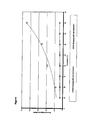
- Bei der Ermittlung der Wärmeleitfähigkeiten gemäß DIN 12667 und in der Einheit mW/(m*K) dargestellt, wurde überraschenderweise gefunden, dass sich eine hydrophobe Ausrüstung des erfindungsgemäßen Isoliermaterials günstig auf die Änderung der Wärmeleitfähigkeit bei erhöhten Umgebungsfeuchten und höheren Umgebungstemperaturen auswirkt.
- Dieses Verhalten wird in
Figur 9 nochmals verdeutlicht. - Bei höheren Umgebungsfeuchten dringt Feuchtigkeit in das Isoliermaterial ein und erhöht die Wärmeleitfähigkeit innerhalb des Isoliermaterials. Dies bedeutet eine Verringerung der Dämmeigenschaften, sowohl thermisch als auch akustisch.
- Wird ein erfindungsgemäß ausgeführtes Isoliermaterial (1) zusätzlich mit einer hydrophoben Ausrüstung versehen, erfährt es bei Beaufschlagung mit Feuchtigkeit eine deutlich geringere Änderung der Wärmeleitfähigkeit als ein hydrophiles erfindungsgemäßes Isoliermaterial (1).
- Dieses Verhalten ist in
Figur 9 verdeutlicht. - Das erfindungsgemäß ausgeführte Material VP05019BA31 wurde zusätzlich einer Hydrophob-Ausrüstung unterzogen, sodass das Material an Ober- und Unterseite sowie über die gesamte Dicke gesehen hydrophobe Eigenschaften aufweist.
- Beide Isoliermaterialien wurden zwei Stunden mit demineralisiertem Wasser beregnet. Die Muster wurden dann über 24h bei Normklima von 21 °C/65%rel Luftfeuchte gelagert. Abschließend wurde die Wärmeleitfähigkeit bei verschiedenen Temperaturen ermittelt.
- Es zeigte sich, dass nach Lagerung von 24h das hydrophile Isoliermaterial immer noch bis zu 10% Gewichtsprozent Wasser enthielt, wohingegen das hydrophob ausgerüstete Isoliermaterial eine Wasseranteil von kleiner 0,1 Gewichtsprozent aufwies.
- Wie man der
Figur 9 entnehmen kann, bleibt die Wärmeleitfähigkeit eines hydrophob ausgerüsteten Isoliermaterials (1) aufgrund der geringen Feuchte über einen weiten Temperaturbereich konstant, wohingegen das hydrophile, Restwasser enthaltende Isoliermaterial eine deutliche Änderung erfährt. - Zur Bestimmung der Hydrophobie wird ein einfacher Tropfentest durchgeführt. Ein Tropfen demineratisiertes Wasser wird auf eine Fläche des Isoliermaterials aufgebracht. Ist der Tropfen nach einer Zeitspanne von mindestens 2 Stunden nicht in die Struktur eingesunken, wird das Isoliermaterial als hydrophob bezeichnet.
- Das Isoliermaterial muss dabei nicht über die gesamte Dicke oder auf beiden Seiten (2) und (3) hydrophobe Eigenschaften aufweisen, es ist auch möglich nur die Zone hoher Dichte (5) oder die Zone geringer Dichte (6) unter Verwendung von hydrophoben Ausgangsmaterialien herzustellen. Auch eine nur auf einer der Seiten (2) oder (3) befindliche Ausrüstung verhindert das Eindringen von Feuchte in das erfindungsgemäße Isoliermaterial (1). Die Wahl, welche der Seite (2) oder (3), beziehungsweise die Zone hoher Dichte (5) oder die Zone geringer Dichte (6) hydrophobe Eigenschaften aufweisen soll, hängt von der jeweiligen Endanwendung ab, es muss zumindest die Seite, auf welcher das Eindringen von Feuchte am wahrscheinlichsten ist, hydrophobiert sein.
- Gemäß einer weiteren Ausführungsform kann die Seite (2) auch eine Oberflächenbehandlung, wie beispielsweise in einer bevorzugten Ausführungsform als thermische Glättung bis hin zur vollständigen Verhautung ausgeführt, aufweisen. Dies verbessert die mechanische Stabilität, z.B. die Begehbarkeit und hat zusätzlich eine Verbesserung der wasserabweisenden Eigenschaften zur Folge.
- Auch ist es möglich, Folien oder Drucke aufzubringen, welche dann Hinweise für die Anwendung oder Verarbeitungshilfen im Sinne von Skalen aufweisen.
- In einer weiteren Ausführungsform ist es auch möglich, den die Isoliermaterialien bildenden Ausgangsmaterialien wie Schaumstoff oder Vlies weitere Wirkstoffe zuzusetzen, um dem erfindungsgemäßen Isoliermaterial weitere Eigenschaften zu verleihen.
- Beispielsweise können einem erfindungsgemäßen Isoliermaterial (1) flammhemmende Wirkstoffe wie beispielsweise Blähgraphit und / oder wärmespeichernde Zusätze wie z.B. Ruß zugesetzt werden. Auch der Einsatz von bakterizid / fungizid wirkenden Substanzen ist möglich. Dabei können diese Wirkstoffe in die Zonen hoher Dichte (5) und geringer Dichte (6) mechanisch eingebettet werden, es ist aber auch möglich, die Wirkstoffe direkt in die Ausgangsstoffe, z.B. in die Fasern einzubetten.
- Erfindungsgemäß hergestellte Isoliermaterialien können je nach Anwendungszweck sowohl als Platten als auch in Form von Rollen hergestellt werden. Wird das Isoliermaterial in Form von Platten konfektioniert, können zusätzlich an den Außenseiten der Platten Nuten und Federn eingebracht werden, sodass eine formschlüssige, flächendeckende Verlegung ohne Unterbrechung der Isolationswirkung möglich ist.
Tabelle 1: Parameter Handelsübliches Isoliermaterial nach dem Stand der Technik Erfindungsgemäßes Isoliermaterial Erfindungsgemäßes Isoliermaterial Bezeichnung/Aufbau VP080198A31/Homogen VP05019BA31 - PHIL/Zweilagig VP05019BA31-PHOB/Zweilagig Faserzusammensetzung Homogener Aufbau aus Zone hoher Dichte (5) Zone hoher Dichte (5) 50% PET/CoPET-Schmelzfaser 4.4 dtex, 50% PET/CoPET-Sehmelzfaser 4.4 dtex, 50% PET/CoPET-Schmelzfaser 4.4 dtex. 25% PET-Matrixfaser 1,7 dtex, 30% PET-Matrixfaser 1.7 dtex, 30% PET-Matrixfaser 1,7 dtex, 25% PET-Matrixfaser 3.3 dtex 20%PEr-Matrixfaser 3.3 dtex 20% PET -Matrixfaser 3.3 dtex Zone geringer Dichte (6) Zone geringer Dichte (6) 30% PET/CoPET-Schmeizfaser 4.4 dtex, 30% PET/CePET-Schmelzfaser 4.4 dtex, 55% PET-Matrixfaser 1,7 dtex, 55% PET-Matrixfaser 1.7 dtex, 15% PET-Matrixfaser 3.3 dtex 15% PF-T-Matrixfaser 3.3 dtex Charackteristik Hydrophil Hydrophil Hydrophob Flachengewicht (in g/m2, gemäß WSP 2400 Gesamt: 2900 Gesamt: 2900 130.1(05) Zone hoher Dichte (5): 1400 Zone hoher Dichte (5) 1300 Zone geringer Dichte (6):1500 Zone geringer Dichte (6): 1600 Dicke (in mm, gemäß WSP 120.6 (05) bei 105 Gesamt: 140 Gesamt: 121 0,02kPa) Zone hoher Dichte (5): 50 Zone hoher Dichte (5): 43 Zone geringer Dichte (6):90 Zone geringer Dichte (6):78 Dichte (in kg/m2) 22,8 Gesamt: 20,7 Gesamt- 20.7 Zone hoher Dichte (5); 28.0 Zone hoher Dichte (5): 30,2 Zone geringer Dichte (6):16,6 Zone geringer Dichte (6):20,5 Eindrückhärte Unterseite (in N) 5,2 1,9 2,9 Eindrückhärte Oberseite (in N) 5,3 5,7 7,3 Verhältnis Eindrückhärte Oberseite (2) zu Unterseite (3) 1,0 3,0 2,5 Wärmeleitfähigkeit im trockenen Zustand, gemessen bei 10°C (in W/(m·K), gemäß DIN 12667) 0,0351 0,0338 0,0338 wärmaleitfähigkeit nach Beregnungstest und 24h Klimatisierung. gemessen bei 10°C (in W/(m·K), gemäß DIN 12667) 0.0382 0,0360 0,0343 -
- 1
- Erfindungsgemäßes Isolationsmaterial
- 2
- Oberseite
- 3
- Unterseite
- 4
- Dicke
- 5
- Zone hoher Dichte
- 6
- Zone geringer Dichte
- 7
- Isolationsmaterial nach dem Stand der Technik
- 8
- Wandung
- 9
- Vorsprung
- 10
- Kamin
- 11
- Halterung
- 12
- Kraftaufnehmer
- 13
- Druckfinne
- 14
- Prüftisch
- 15
- Prüfling
- 16
- Eindrückhärte Oberseite
- 17
- Eindrückhärte Unterseite
Claims (22)
- Isolationsmaterial (1) für die thermische und/oder akustische Isolierung, aufweisend eine Oberseite (2), eine Unterseite (3) und eine Dicke (4)
dadurch gekennzeichnet, dass
dass das Isolationsmaterial mindestens eine Zone hoher Dichte (5) und eine Zone geringer Dichte (6) enthält und dass
die Zone hoher Dichte (5) des Isoliermaterials (1) eine Eindrückhärte aufweist, die mindestens das Zweifache der Eindrückhärte der Zone geringer Dichte (6) beträgt. - Isolationsmaterial (1) nach Anspruch 1
dadurch gekennzeichnet, dass
die Zone geringer Dichte (6) mindestens 60% der Dicke (4) des Isolationsmaterials einnimmt. - Isolationsmaterial (1) nach Anspruch 1 oder 2
dadurch gekennzeichnet, dass
das Flächengewicht der Zone hoher Dichte (5) maximal 50% des Gesamtflächengewichts einnimmt. - Isolationsmaterial (1) nach Anspruch 1 bis 3
dadurch gekennzeichnet, dass
das Isolationsmaterial aus einem Vliesstoff gebildet wird. - Isolationsmaterial (1) nach Anspruch 1 bis 3
dadurch gekennzeichnet, dass
das Isolationsmaterial aus einem Schaumstoff gebildet wird - Isolationsmaterial (1) nach Anspruch 1 bis 4
dadurch gekennzeichnet, dass
der Vliesstoff aus Matrix-Stapelfasern und thermoplastischen Schmelzfasern gebildet wird. - Isolationsmaterial (1) nach Anspruch 5
dadurch gekennzeichnet, dass
die Matrix-Stapelfasern aus Naturfasern und/oder Synthesefasern oder aus Mischungen der beiden bestehen. - Isolationsmaterial (1) nach einem der vorhergehenden Ansprüche
dadurch gekennzeichnet, dass
der Anteil an thermoplastischen Schmelzfasern in den Zonen hoher Dichte (5) mindestens 30% beträgt. - Isolationsmaterial (1) nach einem der vorhergehenden Ansprüche
dadurch gekennzeichnet, dass
der Anteil an thermoplastischen Schmelzfasern in den Zonen geringer Dichte (6) maximal 50% beträgt. - Isolationsmaterial (1) nach einem der vorhergehenden Ansprüche
dadurch gekennzeichnet, dass
die Dicke des Isoliermaterials zwischen 20 und 300mm liegt - Isolationsmaterial (1) nach einem der vorhergehenden Ansprüche
dadurch gekennzeichnet, dass
das Flächengewicht des Isoliermaterials zwischen 300 und 4000 g/qm liegt - Isolationsmaterial (1) nach einem der vorhergehenden Ansprüche
dadurch gekennzeichnet, dass
mindestens eine Seite des Isoliermaterials hydrophobe Eigenschaften aufweist. - Isolationsmaterial (1) nach einem der vorhergehenden Ansprüche
dadurch gekennzeichnet, dass
mindestens eine Seite des Isoliermaterials eine Oberflächenbehandlung aufsweist. - Isolabonsmaterial (1) nach einem der vorhergehenden Ansprüche
dadurch gekennzeichnet, dass
das Isoliermaterial brandhemmende Wirkstoffe enthält - Isolationsmaterial (1) nach einem der vorhergehenden Ansprüche
dadurch gekennzeichnet, dass
das isoliermaterial wärmespeichernde Wirkstoffe enthält. - Isolationsmaterial (1) nach einem der vorhergehenden Ansprüche
dadurch gekennzeichnet, dass
das Isoliermaterial biozide und/oder fungizide Wirkstoffe enthält. - Isolationsmaterial (1) nach einem der vorhergehenden Ansprüche
dadurch gekennzeichnet, dass
das Isoliermaterial in Form von Platten vorliegt - Isolationsmaterial (1) nach einem der vorhergehenden Ansprüche
dadurch gekennzeichnet, dass
das Isoliermaterial in Form von Rollen vorliegt - Isolationsmaterial (1) nach Anspruch 18
dadurch gekennzeichnet, dass
das Isoliermaterial in an den Kanten eine Nut- und Feder Struktur aufweist - Verwendung eines Isolationsmaterial (1) nach einem der Ansprüche 1 bis 19 als Dach- oder Gebäudeisolierung
- Verwendung eines Isolationsmaterial (1) nach einem der Ansprüche 1 bis 19 als Isoliermaterial für Heiz- oder Kühlanlagen
- Verwendung eines Isolationsmaterial (1) nach einem der Ansprüche 1 bis 19 als Isoliermaterial für Rohrleitungssysteme
Applications Claiming Priority (1)
| Application Number | Priority Date | Filing Date | Title |
|---|---|---|---|
| DE102010011386A DE102010011386A1 (de) | 2010-03-12 | 2010-03-12 | Isolationsmaterial |
Publications (3)
| Publication Number | Publication Date |
|---|---|
| EP2369078A2 true EP2369078A2 (de) | 2011-09-28 |
| EP2369078A3 EP2369078A3 (de) | 2014-07-09 |
| EP2369078B1 EP2369078B1 (de) | 2016-06-29 |
Family
ID=44144753
Family Applications (1)
| Application Number | Title | Priority Date | Filing Date |
|---|---|---|---|
| EP11000896.8A Active EP2369078B1 (de) | 2010-03-12 | 2011-02-04 | Isolationsmaterial |
Country Status (3)
| Country | Link |
|---|---|
| EP (1) | EP2369078B1 (de) |
| DE (2) | DE102010011386A1 (de) |
| PL (1) | PL2369078T3 (de) |
Cited By (1)
| Publication number | Priority date | Publication date | Assignee | Title |
|---|---|---|---|---|
| EP2910672A1 (de) * | 2014-02-12 | 2015-08-26 | Sandler AG | Unterdeckplatte |
Citations (2)
| Publication number | Priority date | Publication date | Assignee | Title |
|---|---|---|---|---|
| DE19512767A1 (de) | 1995-04-05 | 1996-10-10 | Hoechst Trevira Gmbh & Co Kg | Rollbare Wärmedämmung auf Basis vollsynthetischer Fasern |
| WO2008012680A2 (en) | 2006-04-27 | 2008-01-31 | Dow Global Technologies, Inc. | Polymeric fiber insulation batts for residential and commercial construction applications |
Family Cites Families (4)
| Publication number | Priority date | Publication date | Assignee | Title |
|---|---|---|---|---|
| DE3701592A1 (de) * | 1987-01-21 | 1988-08-04 | Rockwool Mineralwolle | Verfahren zur kontinuierlichen herstellung einer faserdaemmstoffbahn und vorrichtung zur durchfuehrung des verfahrens |
| DE19922592A1 (de) * | 1999-05-17 | 2000-11-23 | Gruenzweig & Hartmann | Dämmstoffelement aus Mineralwolle sowie Verfahren zu seiner Herstellung und Verwendung desselben |
| DE10248326C5 (de) * | 2002-07-19 | 2014-06-12 | Deutsche Rockwool Mineralwoll Gmbh & Co. Ohg | Dämmschicht aus Mineralfasern |
| DK1559844T3 (da) * | 2004-01-31 | 2007-10-29 | Rockwool Mineralwolle | Isoleringselement og kombineret varmeisoleringssystem |
-
2010
- 2010-03-12 DE DE102010011386A patent/DE102010011386A1/de not_active Withdrawn
- 2010-03-12 DE DE202010017608U patent/DE202010017608U1/de not_active Expired - Lifetime
-
2011
- 2011-02-04 EP EP11000896.8A patent/EP2369078B1/de active Active
- 2011-02-04 PL PL11000896.8T patent/PL2369078T3/pl unknown
Patent Citations (2)
| Publication number | Priority date | Publication date | Assignee | Title |
|---|---|---|---|---|
| DE19512767A1 (de) | 1995-04-05 | 1996-10-10 | Hoechst Trevira Gmbh & Co Kg | Rollbare Wärmedämmung auf Basis vollsynthetischer Fasern |
| WO2008012680A2 (en) | 2006-04-27 | 2008-01-31 | Dow Global Technologies, Inc. | Polymeric fiber insulation batts for residential and commercial construction applications |
Non-Patent Citations (1)
| Title |
|---|
| "Vliesstoffe", 2000, WILEY-VERLAG |
Cited By (1)
| Publication number | Priority date | Publication date | Assignee | Title |
|---|---|---|---|---|
| EP2910672A1 (de) * | 2014-02-12 | 2015-08-26 | Sandler AG | Unterdeckplatte |
Also Published As
| Publication number | Publication date |
|---|---|
| PL2369078T3 (pl) | 2016-12-30 |
| DE102010011386A1 (de) | 2011-09-15 |
| EP2369078A3 (de) | 2014-07-09 |
| DE202010017608U1 (de) | 2012-04-05 |
| EP2369078B1 (de) | 2016-06-29 |
Similar Documents
| Publication | Publication Date | Title |
|---|---|---|
| EP0435001B1 (de) | Schichtstoff | |
| EP0868556B1 (de) | Fasergebilde-aerogel-verbundmaterial enthaltend mindestens ein thermoplastisches fasermaterial, verfahren zu seiner herstellung, sowie seine verwendung | |
| EP3245343B1 (de) | Kapillaraktive elemente umfassender wärmedämmformkörper | |
| EP1678386A1 (de) | D mmstoffelement aus minearalfaserfilz f r den klemmenden einbau zwischen balken und dgl. | |
| DE3145266C2 (de) | Dach- und Abdichtungsbahn | |
| EP0578107A1 (de) | Vliesstoff aus natürlichen Fasern und Verwendungen dafür | |
| EP1182177B2 (de) | Dämmstoffelement sowie Verfahren und Vorrichtung zur Herstellung eines Dämmstoffelements, insbesondere einer roll- und/oder wickelbaren Dämmstoffbahn aus Mineralfasern | |
| EP2369078B1 (de) | Isolationsmaterial | |
| EP0805752B1 (de) | Flächenartiges verbundisoliermaterialsystem und verfahren zu dessen herstellung | |
| DE2914173C2 (de) | Imprägnierte Zylinderkopfdichtung und ihr Herstellungsverfahren | |
| EP2910672B1 (de) | Unterdeckplatte | |
| EP0591658B1 (de) | Wärmedämmelement und Verfahren zu dessen Herstellung | |
| DE102004030393A1 (de) | Verfahren zur Herstellung eines dreidimensional geformten Vliesstoffes, Vorrichtung zur Benutzung in dem Verfahren, danach erhaltener dreidimensional geformter Vliesstoff und seine Verwendung | |
| DE10129858A1 (de) | Oberflächenbeschichtung von akustisch wirksamen Schaumstoffmaterialien | |
| EP3249084A1 (de) | Verfahren zur herstellung eines garnes, verfahren zur herstellung eines vlieses und vlies | |
| DE60222691T2 (de) | Mineralfaservliese | |
| DE19743033C2 (de) | Belag aus textilem Material für temperaturbeanspruchte Transportrollen und Verfahren zur Herstellung des Belages | |
| DE9319699U1 (de) | Wärmedämmelement | |
| EP2360304B1 (de) | Vorkonfektionierte Trägereinlage und beschichtete Dachbahnen | |
| DE10007556A1 (de) | Trägerkomponente für Formteile | |
| DE19749615C2 (de) | Isolationsschlauch | |
| DE19952432A1 (de) | Schichtstoff | |
| DE9422018U1 (de) | Dämmstoff, insbesondere zur Schall- und Wärmedämmung | |
| EP2711478A2 (de) | Dämmstoff | |
| DE29719855U1 (de) | Isolationsschlauch |
Legal Events
| Date | Code | Title | Description |
|---|---|---|---|
| PUAI | Public reference made under article 153(3) epc to a published international application that has entered the european phase |
Free format text: ORIGINAL CODE: 0009012 |
|
| 17P | Request for examination filed |
Effective date: 20110217 |
|
| AK | Designated contracting states |
Kind code of ref document: A2 Designated state(s): AL AT BE BG CH CY CZ DE DK EE ES FI FR GB GR HR HU IE IS IT LI LT LU LV MC MK MT NL NO PL PT RO RS SE SI SK SM TR |
|
| AX | Request for extension of the european patent |
Extension state: BA ME |
|
| PUAL | Search report despatched |
Free format text: ORIGINAL CODE: 0009013 |
|
| AK | Designated contracting states |
Kind code of ref document: A3 Designated state(s): AL AT BE BG CH CY CZ DE DK EE ES FI FR GB GR HR HU IE IS IT LI LT LU LV MC MK MT NL NO PL PT RO RS SE SI SK SM TR |
|
| AX | Request for extension of the european patent |
Extension state: BA ME |
|
| RIC1 | Information provided on ipc code assigned before grant |
Ipc: E04B 1/80 20060101AFI20140602BHEP Ipc: E04B 1/86 20060101ALI20140602BHEP |
|
| GRAP | Despatch of communication of intention to grant a patent |
Free format text: ORIGINAL CODE: EPIDOSNIGR1 |
|
| INTG | Intention to grant announced |
Effective date: 20160216 |
|
| GRAS | Grant fee paid |
Free format text: ORIGINAL CODE: EPIDOSNIGR3 |
|
| GRAA | (expected) grant |
Free format text: ORIGINAL CODE: 0009210 |
|
| RBV | Designated contracting states (corrected) |
Designated state(s): AT BE CZ DE FR GB LU NL PL SE |
|
| AK | Designated contracting states |
Kind code of ref document: B1 Designated state(s): AT BE CZ DE FR GB LU NL PL SE |
|
| REG | Reference to a national code |
Ref country code: GB Ref legal event code: FG4D Free format text: NOT ENGLISH |
|
| REG | Reference to a national code |
Ref country code: AT Ref legal event code: REF Ref document number: 809231 Country of ref document: AT Kind code of ref document: T Effective date: 20160715 |
|
| REG | Reference to a national code |
Ref country code: DE Ref legal event code: R096 Ref document number: 502011010016 Country of ref document: DE |
|
| REG | Reference to a national code |
Ref country code: NL Ref legal event code: FP |
|
| REG | Reference to a national code |
Ref country code: SE Ref legal event code: TRGR |
|
| REG | Reference to a national code |
Ref country code: FR Ref legal event code: PLFP Year of fee payment: 7 |
|
| REG | Reference to a national code |
Ref country code: DE Ref legal event code: R097 Ref document number: 502011010016 Country of ref document: DE |
|
| PLBE | No opposition filed within time limit |
Free format text: ORIGINAL CODE: 0009261 |
|
| STAA | Information on the status of an ep patent application or granted ep patent |
Free format text: STATUS: NO OPPOSITION FILED WITHIN TIME LIMIT |
|
| 26N | No opposition filed |
Effective date: 20170330 |
|
| REG | Reference to a national code |
Ref country code: FR Ref legal event code: PLFP Year of fee payment: 8 |
|
| PGFP | Annual fee paid to national office [announced via postgrant information from national office to epo] |
Ref country code: NL Payment date: 20230222 Year of fee payment: 13 |
|
| PGFP | Annual fee paid to national office [announced via postgrant information from national office to epo] |
Ref country code: LU Payment date: 20230217 Year of fee payment: 13 Ref country code: FR Payment date: 20230222 Year of fee payment: 13 Ref country code: CZ Payment date: 20230127 Year of fee payment: 13 Ref country code: AT Payment date: 20230223 Year of fee payment: 13 |
|
| PGFP | Annual fee paid to national office [announced via postgrant information from national office to epo] |
Ref country code: SE Payment date: 20230220 Year of fee payment: 13 Ref country code: PL Payment date: 20230130 Year of fee payment: 13 Ref country code: GB Payment date: 20230220 Year of fee payment: 13 Ref country code: BE Payment date: 20230220 Year of fee payment: 13 |
|
| REG | Reference to a national code |
Ref country code: SE Ref legal event code: EUG |
|
| REG | Reference to a national code |
Ref country code: NL Ref legal event code: MM Effective date: 20240301 |
|
| PG25 | Lapsed in a contracting state [announced via postgrant information from national office to epo] |
Ref country code: LU Free format text: LAPSE BECAUSE OF NON-PAYMENT OF DUE FEES Effective date: 20240204 |
|
| REG | Reference to a national code |
Ref country code: AT Ref legal event code: MM01 Ref document number: 809231 Country of ref document: AT Kind code of ref document: T Effective date: 20240204 |
|
| GBPC | Gb: european patent ceased through non-payment of renewal fee |
Effective date: 20240204 |
|
| PG25 | Lapsed in a contracting state [announced via postgrant information from national office to epo] |
Ref country code: CZ Free format text: LAPSE BECAUSE OF NON-PAYMENT OF DUE FEES Effective date: 20240204 |
|
| PG25 | Lapsed in a contracting state [announced via postgrant information from national office to epo] |
Ref country code: AT Free format text: LAPSE BECAUSE OF NON-PAYMENT OF DUE FEES Effective date: 20240204 |
|
| PG25 | Lapsed in a contracting state [announced via postgrant information from national office to epo] |
Ref country code: LU Free format text: LAPSE BECAUSE OF NON-PAYMENT OF DUE FEES Effective date: 20240204 Ref country code: CZ Free format text: LAPSE BECAUSE OF NON-PAYMENT OF DUE FEES Effective date: 20240204 Ref country code: AT Free format text: LAPSE BECAUSE OF NON-PAYMENT OF DUE FEES Effective date: 20240204 |
|
| PG25 | Lapsed in a contracting state [announced via postgrant information from national office to epo] |
Ref country code: NL Free format text: LAPSE BECAUSE OF NON-PAYMENT OF DUE FEES Effective date: 20240301 |
|
| PG25 | Lapsed in a contracting state [announced via postgrant information from national office to epo] |
Ref country code: NL Free format text: LAPSE BECAUSE OF NON-PAYMENT OF DUE FEES Effective date: 20240301 |
|
| REG | Reference to a national code |
Ref country code: BE Ref legal event code: MM Effective date: 20240229 |
|
| PG25 | Lapsed in a contracting state [announced via postgrant information from national office to epo] |
Ref country code: BE Free format text: LAPSE BECAUSE OF NON-PAYMENT OF DUE FEES Effective date: 20240229 |
|
| PG25 | Lapsed in a contracting state [announced via postgrant information from national office to epo] |
Ref country code: GB Free format text: LAPSE BECAUSE OF NON-PAYMENT OF DUE FEES Effective date: 20240204 |
|
| PG25 | Lapsed in a contracting state [announced via postgrant information from national office to epo] |
Ref country code: FR Free format text: LAPSE BECAUSE OF NON-PAYMENT OF DUE FEES Effective date: 20240229 |
|
| PG25 | Lapsed in a contracting state [announced via postgrant information from national office to epo] |
Ref country code: GB Free format text: LAPSE BECAUSE OF NON-PAYMENT OF DUE FEES Effective date: 20240204 Ref country code: FR Free format text: LAPSE BECAUSE OF NON-PAYMENT OF DUE FEES Effective date: 20240229 Ref country code: BE Free format text: LAPSE BECAUSE OF NON-PAYMENT OF DUE FEES Effective date: 20240229 |
|
| PG25 | Lapsed in a contracting state [announced via postgrant information from national office to epo] |
Ref country code: PL Free format text: LAPSE BECAUSE OF NON-PAYMENT OF DUE FEES Effective date: 20240204 |
|
| PG25 | Lapsed in a contracting state [announced via postgrant information from national office to epo] |
Ref country code: SE Free format text: LAPSE BECAUSE OF NON-PAYMENT OF DUE FEES Effective date: 20240205 |
|
| PGFP | Annual fee paid to national office [announced via postgrant information from national office to epo] |
Ref country code: DE Payment date: 20260225 Year of fee payment: 16 |