EP2369063A1 - Outil de forage et de malaxage comportant un tambour à dents déportées - Google Patents
Outil de forage et de malaxage comportant un tambour à dents déportées Download PDFInfo
- Publication number
- EP2369063A1 EP2369063A1 EP11159712A EP11159712A EP2369063A1 EP 2369063 A1 EP2369063 A1 EP 2369063A1 EP 11159712 A EP11159712 A EP 11159712A EP 11159712 A EP11159712 A EP 11159712A EP 2369063 A1 EP2369063 A1 EP 2369063A1
- Authority
- EP
- European Patent Office
- Prior art keywords
- teeth
- drilling
- soil
- tool according
- support
- Prior art date
- Legal status (The legal status is an assumption and is not a legal conclusion. Google has not performed a legal analysis and makes no representation as to the accuracy of the status listed.)
- Granted
Links
Images


Classifications
-
- E—FIXED CONSTRUCTIONS
- E02—HYDRAULIC ENGINEERING; FOUNDATIONS; SOIL SHIFTING
- E02F—DREDGING; SOIL-SHIFTING
- E02F3/00—Dredgers; Soil-shifting machines
- E02F3/04—Dredgers; Soil-shifting machines mechanically-driven
- E02F3/18—Dredgers; Soil-shifting machines mechanically-driven with digging wheels turning round an axis, e.g. bucket-type wheels
- E02F3/22—Component parts
- E02F3/24—Digging wheels; Digging elements of wheels; Drives for wheels
- E02F3/241—Digging wheels; Digging elements of wheels; Drives for wheels digging wheels
-
- E—FIXED CONSTRUCTIONS
- E02—HYDRAULIC ENGINEERING; FOUNDATIONS; SOIL SHIFTING
- E02D—FOUNDATIONS; EXCAVATIONS; EMBANKMENTS; UNDERGROUND OR UNDERWATER STRUCTURES
- E02D17/00—Excavations; Bordering of excavations; Making embankments
- E02D17/13—Foundation slots or slits; Implements for making these slots or slits
-
- E—FIXED CONSTRUCTIONS
- E02—HYDRAULIC ENGINEERING; FOUNDATIONS; SOIL SHIFTING
- E02D—FOUNDATIONS; EXCAVATIONS; EMBANKMENTS; UNDERGROUND OR UNDERWATER STRUCTURES
- E02D3/00—Improving or preserving soil or rock, e.g. preserving permafrost soil
- E02D3/12—Consolidating by placing solidifying or pore-filling substances in the soil
-
- E—FIXED CONSTRUCTIONS
- E02—HYDRAULIC ENGINEERING; FOUNDATIONS; SOIL SHIFTING
- E02F—DREDGING; SOIL-SHIFTING
- E02F3/00—Dredgers; Soil-shifting machines
- E02F3/04—Dredgers; Soil-shifting machines mechanically-driven
- E02F3/18—Dredgers; Soil-shifting machines mechanically-driven with digging wheels turning round an axis, e.g. bucket-type wheels
- E02F3/20—Dredgers; Soil-shifting machines mechanically-driven with digging wheels turning round an axis, e.g. bucket-type wheels with tools that only loosen the material, i.e. mill-type wheels
- E02F3/205—Dredgers; Soil-shifting machines mechanically-driven with digging wheels turning round an axis, e.g. bucket-type wheels with tools that only loosen the material, i.e. mill-type wheels with a pair of digging wheels, e.g. slotting machines
Definitions
- the present invention relates to the technical field of drilling machines, particularly but not exclusively for producing walls in the soil resulting from the mixing of soil with an additional binder.
- the present invention does not relate to the field of milling cutter type tools for excavating a trench while discharging the cutting debris out of the trench.
- the techniques of mixing soil and a binder are nowadays commonly used to improve the floors of foundations.
- the tools used, of the Cutter Soil Mixing (CSM) type are capable of drilling in a multitude of terrains, especially in order to mix in situ cement grout injected at the bottom end of the tool with the ground, thanks to which the quantity of cuttings produced by the excavation of diaphragm walls is substantially reduced.
- the machines are equipped with two pairs of parallel axis drums mounted on a supporting structure.
- An example of such a machine is described in the document FR 2 899 608 .
- On the periphery of these drums are fixed cutting teeth mounted on supports attached to the drums.
- the drums are rotated by hydraulic motors located therein.
- This engine system housed in the drums limits the risk of jamming drums inside the trench. However, even if the jamming is reduced, it is still present, especially when the drums have a long axial length.
- a first object of the invention relates to a rotary drum for a drilling and kneading tool of the aforementioned type, said drum having an axis of rotation, an outer face and an inner face orthogonal to the axis of rotation, and a surface device extending axially between the inner face and the outer face, said drum being provided with a plurality of cutting teeth mounted at the end of supports extending radially from the peripheral surface.
- the thickness of the bore corresponds substantially to the axial size of the pairs of drums.
- An object of the invention is to provide a drilling tool and soil mixing for making trenches of great thickness while being substantially less subject to jamming.
- the drum comprises at least one tooth, the first tooth, which is mounted on a first support inclined at an angle of at least 10 ° so that the first tooth is axially widely offset relative to the outer face of the drum .
- the drum of the tool according to the invention is able to drill and mix a volume of soil that is substantially axially thicker than the axial length of the peripheral surface of said drum.
- the body of the drum that carries the cutting teeth has an axial length substantially less than that of the prior art, whereby the drum according to the invention has less risks of vertical jamming than the previous drums.
- the drum facilitates the vertical movement of the tool.
- the outer face of the drum is that which is intended to be opposite one of the walls of the trench, while the inner face is the one which is intended to be opposite an element of the mixing tool for supporting the drums, or another drum of the tool.
- a support can carry a tooth, two teeth or more.
- the supports form mixing blades, while the teeth scratch and destructure the soil.
- the supports have an axial thickness small relative to their radial length and their angular extent so that they have the general shape of a shark fin.
- Such a form is particularly well suited for mixing in clay soil.
- the first support is inclined with respect to a plane in which the outer face extends.
- this plane is orthogonal to the axis of rotation of the drum.
- the support When the first support is fixed to the edge of the peripheral surface, the support may for example be inclined at an angle between 10 ° and 40 ° relative to said plane.
- the drum comprises at least one second support provided with a second cutting tooth, said second support being disposed axially between the first support and the inner face.
- the second support is preferably inclined with respect to a plane orthogonal to the axis of rotation.
- the first tooth and the second tooth have substantially the same radial height.
- the drum according to the invention comprises at least a third support provided with a third cutting tooth, said third support being disposed axially between the second support and the inner face.
- the third tooth advantageously has the same radial height as the first and second teeth.
- the drum according to the invention comprises a first group of teeth consisting of first teeth mounted on first supports, a second group of teeth constituted by second teeth mounted on second supports and a third group of teeth. constituted by third teeth mounted on third supports, and, moreover, two angularly adjacent teeth of one of the groups of teeth are spaced at an angle substantially equal to 90 °.
- the peripheral surface has successively a first tooth, a second tooth and a third tooth.
- two successive teeth are spaced at an angle substantially equal to 30 °.
- the first and third teeth that are adjacent to this second tooth are spaced from the latter by an angle substantially equal to 30 °, so as to ensure continuous drilling / mixing.
- some of the teeth are advantageously inclined relative to their supports.
- two angularly adjacent teeth belonging to one of the groups of teeth do not have the same inclination with respect to their supports.
- the latter will be inclined relative to each other so as to form a "Y".
- the drill and soil mixing tool is particularly advantageous insofar as it has a small footprint compared to the thickness of the trench, so as to promote the vertical movement of the mixing assembly , mainly when the trench is filled with a binder-cement mixture which is generally dense and thick, and thus conducive to jamming the mixing assembly.
- the drum further comprises at least one inclined scraper which is fixed to the support and which extends to the peripheral surface of each drum.
- the scraper advantageously comprises an opening allowing the teeth of the second group of teeth to pass during the rotation of the drums.
- the axial width of the opening is substantially equal to or slightly greater than the axial thickness of the second supports.
- the motor means are preferably housed in the drums.
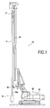
- the drilling and soil kneading tool 12 comprises a guide beam 14 of constant profile and preferably rectangular section. Furthermore, a motorized mixing unit 16 is fixed to the lower end 14a of the beam 14.
- the guide beam 14 makes it possible to transmit the thrust and traction forces to the mixing assembly 16. It also makes it possible to protect the supply lines of the tool by binding, as well as the supply lines of the motors with hydraulic energy of the motors.
- the beam 14 is connected to a vertical mast 20 by means of guiding and driving means 17,18.
- the mast is supported by a track carrier 22 on which is installed a hydraulic power generation system 24.
- the mixing assembly is moved vertically in the ground to make a trench panel by drilling the soil and mixing the cuttings with the binder.
- the guide beam 14 at the lower end of which is fixed the entire kneading 16.
- the entire kneading 16 consists of a support member 26 and two pairs rotary drums 28 according to the invention.
- the beam 14 also called “Kelly” has transverse dimensions small compared to the width of the mixing assembly 16.
- Motor means preferably hydraulic, dedicated to the rotational drive of the drums 28, are preferably housed inside said drums. This type of engines being well known elsewhere, it will not be described in more detail.
- a nozzle 30 connected to a feed pipe extending in the beam 14.
- the rotary drum 28 has an axis of rotation A and an outer face 32 and an inner face 34 which are orthogonal to the axis of rotation A.
- the adjectives "axial”, “radial” and “angular” are considered with respect to this axis A.
- the drum 28 further has a peripheral surface 36 which extends axially between the inner face 34 and the outer face 32.
- the axial length L of the peripheral surface of the drum is of the order of 250 mm, while the diameter D1 of its peripheral surface 36 is of the order of 800 mm.
- each of the drums 28 is provided with a plurality of cutting teeth 40 which are mounted on supports 42. These supports 42 form mixing blades, preferably in the form of shark fins. , allowing to mix the cuttings with the binder.
- the radial height of each of the cutting teeth is of the order of 700 mm.
- the outside diameter D2 of the drum is of the order of 1 400 mm.
- At least one of the drums 28 has a first group of teeth 40 ' mounted on supports 42'.
- the teeth 40 ' of the first group of teeth are those which are mounted on those of the supports which are fixed closest to the outer face 32.
- each of the first supports 42 ' is arranged so that the outer face 32 is arranged axially between the first tooth 40' associated and the inner face 34.
- the first tooth 40 ' is arranged axially at beyond the outer face 32.
- each of the supports 42 ' is widely inclined with respect to a plane P in which the outer face 32 extends .
- the angle of inclination ⁇ is greater than or equal to 10 ° and may for example be chosen between 10 ° and 40 °.
- the axial distance between the first teeth 40 ' and the inner face 34 is about 50% larger than the axial length L of the peripheral surface 36.
- the axial distance between the first teeth 40' and the inner face 34 is of the order of 400 mm.
- the first supports 42 ' forming blades can advantageously knead a volume of soil substantially greater than that which is kneaded by the tools of the prior art.
- the volume of additional kneaded soil referenced Z has substantially the geometric shape of a thick disk having for radius the radial height of the first teeth 40 ' considered from the axis A, and for axial thickness, the axial distance between the first teeth 40 'and the outer face 32.
- the volume kneaded by a MSC standard tool is limited to the annular volume located between the peripheral surface 36 and the tips of the teeth.
- the soil boring and kneading tool according to the invention can drill and mix a volume of soil that is substantially thicker than the axial length of the peripheral surface 36 of the drum.
- the drum 28 according to the invention also comprises a second set of teeth consisting of second teeth 40 "mounted on the second supports 42" attached to the peripheral surface, and a third set of teeth constituted by third teeth 40 "' mounted on third supports 42"' also attached to the peripheral surface.
- the second supports 42 " are arranged axially between the first and third supports 42 ', 42'''.
- the second supports 42 " are also inclined with respect to a plane orthogonal to the axis of rotation A, so that, in this example, the second supports 42" are substantially parallel to the first supports 42 '.
- the axial distance between the first teeth 40 ' and the second teeth 40 " is substantially equal to the axial distance between the second teeth 40" and the third teeth 40 "'.
- the direction of rotation of the drum 28 is symbolized by the arrow F on the figure 4 . It can then be seen that, seen in this direction of rotation F, the peripheral surface 36 successively has a first tooth 40 ', a second tooth 40 " and a third tooth 40"'.
- the developed length LD of the peripheral surface 36 is substantially equal to 2500 mm, since the diameter of the peripheral surface of the drum 28 is substantially equal to 800 mm.
- some of the teeth are inclined at an angle ⁇ relative to their supports.
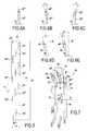
- the Figures 6A to 6E illustrate, in a nonlimiting manner, different configurations of the teeth of the drum 28.
- the support 42 ''' is not inclined with respect to the peripheral surface 36, and the tooth 40 "' is not inclined relative to its support 42"'.
- the support 42 ''' is not inclined, while the tooth 40 "' is inclined, towards the outer face 32, by an angle ⁇ relative to its support 42"'.
- the value of the angle ⁇ is between 0 ° and 30 °.
- Figures 6D and 6E correspond to first supports, or possibly to second supports, which are inclined as described above.
- the support 42 ' is inclined at an angle ⁇ , towards the outer face, with respect to a plane Q orthogonal to the axis of rotation A.
- the tooth 40' is however not inclined with respect to its support 42 ' .
- figure 6E is different from that of the Figure 6D in that the tooth 40 ' is inclined, towards the inner face, by an angle ⁇ with respect to its support. It is specified that the inclination of the tooth can also be directed towards the outer face.
- two angularly adjacent teeth belonging to one of three groups of teeth do not have the same inclination with respect to their sockets. This is particularly noticeable when referring to the third teeth of the drum of the figure 3 .
- the teeth 40 ', 40 ", 40"' of the first, second and third groups of teeth have the same radial height.
- the kneading tool 12 further comprises one or more scrapers 50 attached to the support member 26 and extending to the peripheral surface 36 of the drum 28 without touching it.
- the scraper 50 is provided with two arms 50a, 50b which delimit an opening 52.
- This opening is inclined with respect to a plane orthogonal to the axis of rotation A, preferably at an angle substantially equal to the angle of inclination second supports, to allow the passage of the latter through the opening during the rotation of the drum.
- the opening has an axial width substantially equal to the axial thickness of the second supports, whereby the arms 50a and 50b can effectively clean the second supports as they pass through the opening.
- the arms 50a and 50b are shaped such that their edges spaced from the opening 52 come into contact with the first and third tooth supports 42 ', 42 ", so that the arms 50a and 50b make it possible to in addition to cleaning the first and third supports by scraping the sludge liable to stick to it during the kneading operation
- the radial ends of the arms 50a, 50b make it possible for them to clean the peripheral surface 36.
- the scraper 50 advantageously allows the drum 28 to be cleaned during its rotation.
Landscapes
- Engineering & Computer Science (AREA)
- Structural Engineering (AREA)
- Mining & Mineral Resources (AREA)
- Civil Engineering (AREA)
- General Engineering & Computer Science (AREA)
- Life Sciences & Earth Sciences (AREA)
- Mechanical Engineering (AREA)
- General Life Sciences & Earth Sciences (AREA)
- Paleontology (AREA)
- Agronomy & Crop Science (AREA)
- Environmental & Geological Engineering (AREA)
- Soil Sciences (AREA)
- Earth Drilling (AREA)
Abstract
Description
- La présente invention concerne le domaine technique des machines de forage, notamment mais non exclusivement pour la réalisation de parois dans le sol résultant du mélange de sol avec un liant additionnel. La présente invention ne concerne cependant pas le domaine des outils du type fraise destiné à excaver une tranchée tout évacuant les débris de coupe hors de la tranchée.
- Les techniques de mélange de sol et d'un liant (en anglais « Soil Mixing ») sont aujourd'hui d'utilisation courante pour améliorer notamment les sols des fondations. Les outils utilisés, du type Cutter Soil Mixing (CSM), sont capables de forer dans une multitude de terrains, notamment afin de mélanger in situ le coulis de ciment injecté à l'extrémité inférieure de l'outil avec le terrain, grâce à quoi on diminue sensiblement la quantité de déblais produits par l'excavation de parois moulées.
- Actuellement, les machines sont équipées de deux paires de tambours à axes parallèles montées sur une structure porteuse. Un exemple d'une telle machine est décrit dans le document
FR 2 899 608 - Un premier objet de l'invention porte sur un tambour rotatif pour un outil de forage et de malaxage du type précité, ledit tambour présentant un axe de rotation, une face extérieure et une face intérieure orthogonales à l'axe de rotation, et une surface périphérique s'étendant axialement entre la face intérieure et la face extérieure, ledit tambour étant muni d'une pluralité de dents de coupe montées à l'extrémité de supports s'étendant radialement depuis la surface périphérique.
- Traditionnellement, lorsque l'on souhaite augmenter l'épaisseur du forage, il est nécessaire d'augmenter la longueur axiale des tambours. En effet, l'épaisseur du forage correspond sensiblement à l'encombrement axial des paires de tambours.
- Cependant, il a été constaté que cette augmentation de la longueur axiale des tambours accroit le risque de coincement vertical de l'outil dans la tranchée, ou, à tout le moins, gêne considérablement la remontée de l'outil. On comprend en effet que plus l'envergure axiale des tambours est importante, plus ils opposent une résistance aux mouvements verticaux de l'outil. Cet aspect est particulièrement important dans la mesure où, contrairement à un outil d'excavation de type fraise, un outil de malaxage de type CSM est amené à se déplacer plusieurs fois verticalement dans la tranchée. On comprend donc qu'un blocage ou un coincement perturbe fortement l'avancement des travaux.
- Un but de l'invention est de proposer un outil de forage et de malaxage de sol permettant de réaliser des tranchées de grande épaisseur tout en étant sensiblement moins sujet au coincement.
- Ce but est atteint par l'outil de forage et de malaxage de sol selon la revendication 1.
- Ainsi, le tambour comporte au moins une dent, la première dent, qui est montée sur un premier support incliné d'un angle au moins égal à 10° de sorte que la première dent soit axialement largement déportée par rapport à la face extérieure du tambour. Par suite, le tambour de l'outil selon l'invention est apte à forer et mélanger un volume de sol qui est sensiblement axialement plus épais que la longueur axiale de la surface périphérique dudit tambour. En d'autres termes, pour une épaisseur de tranchée donnée, le corps du tambour qui porte les dents de coupe présente une longueur axiale sensiblement inférieure à celui de l'art antérieur, grâce à quoi, le tambour selon l'invention présente moins de risques de coincements verticaux que les tambours antérieurs. Autrement dit, on comprend que le tambour facilite le déplacement vertical de l'outil.
- Par ailleurs, au sens de la présente invention, la face extérieure du tambour est celle qui est destinée à être en regard de l'une des parois de la tranchée, tandis que la face intérieure est celle qui est destinée à être en regard d'un élément de l'outil de malaxage destiné à supporter les tambours, ou d'un autre tambour de l'outil.
- On précise également qu'un support peut porter une dent, deux dents ou bien davantage.
- En l'espèce, les supports forment des pales de malaxage, tandis que les dents viennent gratter et déstructurer le sol.
- De préférence, les supports présentent une épaisseur axiale petite par rapport à leur longueur radiale et leur étendue angulaire de telle manière qu'elles présentent la forme générale d'un aileron de requin. Une telle forme est particulièrement bien adaptée pour le malaxage dans des terrains argileux.
- Selon l'invention, le premier support est incliné par rapport à un plan dans lequel s'étend la face extérieure. De préférence, ce plan est orthogonal à l'axe de rotation du tambour.
- Lorsque le premier support est fixé au bord de la surface périphérique, le support pourra par exemple être incliné d'un angle compris entre 10° et 40° par rapport audit plan.
- De manière préférentielle, le tambour comporte au moins un deuxième support muni d'une deuxième dent de coupe, ledit deuxième support étant disposé axialement entre le premier support et la face intérieure. Le deuxième support est préférentiellement incliné par rapport à un plan orthogonal à l'axe de rotation. Par ailleurs et de manière avantageuse, la première dent et la deuxième dent présentent sensiblement la même hauteur radiale.
- Afin d'améliorer encore le malaxage, le tambour selon l'invention comporte au moins un troisième support muni d'une troisième dent de coupe, ledit troisième support étant disposé axialement entre le deuxième support et la face intérieure. En outre, la troisième dent présente avantageusement la même hauteur radiale que les première et deuxième dents.
- Selon un mode de réalisation préférentiel, le tambour selon l'invention comporte un premier groupe de dents constitué de premières dents montées sur des premiers supports, un deuxième groupe de dents constitué par des deuxièmes dents montées sur des deuxièmes supports et un troisième groupe de dents constitué par des troisièmes dents montées sur des troisièmes supports, et, par ailleurs, deux dents angulairement adjacentes de l'un des groupes de dents sont distantes d'un angle sensiblement égal à 90°.
- Autrement dit, il est préférentiellement prévu quatre supports de dents par groupe de dents, de manière à offrir une capacité de forage et un malaxage efficaces tout en laissant le maximum de place pour les écoulements fluides autour des supports.
- De préférence, vue selon le sens de rotation du tambour, la surface périphérique présente successivement une première dent, une deuxième dent, puis une troisième dent.
- De préférence, deux dents successives sont distantes d'un angle sensiblement égal à 30°. Ainsi, pour une deuxième dent donnée, les première et troisième dents qui sont adjacentes à cette deuxième dent sont distantes de cette dernière d'un angle sensiblement égal à 30°, de manière à assurer un forage/malaxage continu.
- Pour améliorer le forage, certaines des dents sont avantageusement inclinées par rapport à leurs supports. De préférence, deux dents angulairement adjacentes appartenant à l'un des groupes de dents ne présentent pas la même inclinaison par rapport à leurs supports. Alternativement, lorsqu'un support porte deux dents, ces dernières seront inclinées l'une par rapport à l'autre de manière à former un « Y ».
- L'outil de forage et de mélange de sol, de type CSM, est particulièrement avantageux dans la mesure où il présente un encombrement faible par rapport à l'épaisseur de la tranchée, de manière à favoriser le déplacement vertical de l'ensemble de malaxage, principalement lorsque la tranchée est remplie d'un mélange de liant-ciment qui est généralement dense et épais, et donc propice à coincer l'ensemble de malaxage.
- De manière particulièrement avantageuse, le tambour comporte en outre au moins un racleur incliné qui est fixé au support et qui s'étend jusqu'à la surface périphérique de chaque tambour.
- Lorsque les tambours de l'outil de forage et de malaxage de sol selon l'invention sont munis de premières, deuxièmes et troisièmes dents, le racleur comporte avantageusement une ouverture permettant le passage des dents du deuxième groupe de dents lors de la rotation des tambours.
- De préférence, la largeur axiale de l'ouverture est sensiblement égale ou légèrement supérieure à l'épaisseur axiale des deuxièmes supports.
- On précise enfin que les moyens moteurs sont préférentiellement logés dans les tambours.
- L'invention sera mieux comprise à la lecture de la description faite ci-après, à titre indicatif mais non limitatif, en référence aux dessins annexés, sur lesquels :
- la
figure 1 représente une machine de malaxage comportant un outil de malaxage de sol conforme à la présente invention ; - la
figure 2 est une vue en perspective de l'outil de malaxage avec sa poutre de guidage ; - la
figure 3 est une vue latérale du tambour qui équipe l'outil de lafigure 2 ; - la
figure 3A est une vue de détail d'un support de dent incliné du tambour de lafigure 2 ; - la
figure 4 est une vue de face du tambour de lafigure 3 ; - la
figure 5 est une vue développée de la surface périphérique du tambour de lafigure 4 ; - les
figures 6A à 6E illustrent différentes configurations des dents de coupe du tambour; et - la
figure 7 illustre la position du racleur par rapport au tambour de lafigure 3 . - Sur la
figure 1 , on a représenté une machine de forage 10 muni d'un outil de forage et de malaxage de sol 12 conforme à l'invention. L'outil de forage et de malaxage de sol 12 comporte une poutre de guidage 14 de profil constant et de préférence à section rectangulaire. Par ailleurs, un ensemble de malaxage 16 motorisé est fixé à l'extrémité inférieure 14a de la poutre 14. La poutre de guidage 14 permet de transmettre les efforts de poussée et de traction sur l'ensemble de malaxage 16. Elle permet également de protéger les conduites d'alimentation de l'outil en liant, ainsi que les conduites d'alimentation des moteurs en énergie hydraulique des moteurs. La poutre 14 est reliée à un mât vertical 20 par le biais de moyens de guidage et d'entrainement 17,18. Le mât est supporté par un porteur à chenilles 22 sur lequel est installé un système de génération de puissance hydraulique 24. - On comprend qu'en commandant les déplacements de la poutre de guidage 14 en montée et en descente, on déplace verticalement l'ensemble de malaxage dans le sol pour réaliser un panneau de tranchée par forage du sol et malaxage des déblais de forage avec le liant.
- Sur la
figure 2 , on a représenté la poutre de guidage 14 à l'extrémité inférieure de laquelle est fixé l'ensemble de malaxage 16. Comme on peut le constater, l'ensemble de malaxage 16 est constitué d'un organe de support 26 et de deux paires de tambours rotatifs 28 conformes à l'invention. On constate également sur cette figure que la poutre 14 également appelée « Kelly » présente des dimensions transversales petites par rapport à l'envergue de l'ensemble de malaxage 16. - Des moyens moteurs, de préférence hydrauliques, dédiés à l'entrainement en rotation des tambours 28, sont préférentiellement logés à l'intérieur desdits tambours. Ce type de moteurs étant bien connu par ailleurs, il ne sera pas décrit plus en détail.
- Pour permettre l'injection de fluide, de préférence un liant, entre les paires de tambours, il est prévu une buse 30 reliée à une conduite d'amenée s'étendant dans la poutre 14.
- A l'aide des
figures 3 et4 , on va maintenant décrire plus en détail la structure de chacun des tambours 28. Selon l'invention, le tambour rotatif 28 présente un axe de rotation A, ainsi qu'une face extérieure 32 et une face intérieure 34 qui sont orthogonales à l'axe de rotation A. Dans la suite de la description, les adjectifs « axial », « radial » et « angulaire » sont considérés par rapport à cet axe A. Le tambour 28 présente en outre une surface périphérique 36 qui s'étend axialement entre la face intérieure 34 et la face extérieure 32. Dans cet exemple, la longueur axiale L de la surface périphérique du tambour est de l'ordre de 250 mm, tandis que le diamètre D1 de sa surface périphérique 36 est de l'ordre de 800 mm. - Comme on le voit sur ces deux figures, chacun des tambours 28 est muni d'une pluralité de dents de coupe 40 qui sont montées sur des supports 42. Ces supports 42 forment des pales de malaxage, de préférence en forme d'ailerons de requin, permettant de mélanger les déblais avec le liant. En l'espèce, la hauteur radiale de chacun des dents de coupe, considérée depuis l'axe A, est de l'ordre de 700 mm. Autrement dit, le diamètre D2 extérieur du tambour (muni des dents) est de l'ordre de 1 400 mm.
- Selon l'invention, au moins l'un des tambours 28 présente un premier groupe de dents 40' montées sur des supports 42'. En se référant à la
figure 3 , on comprend que les dents 40' du premier groupe de dents sont celles qui sont montées sur ceux des supports qui sont fixés au plus près de la face extérieure 32. - Conformément à l'invention, chacun des premiers supports 42' est arrangé de telle sorte que la face extérieure 32 soit disposée axialement entre la première dent 40' associée et la face intérieure 34. Autrement dit, la première dent 40' est disposée axialement au-delà de la face extérieure 32. Pour ce faire, en l'espèce, chacun des supports 42' est largement incliné par rapport à un plan P dans lequel s'étend la face extérieure 32. L'angle d'inclinaison θ, mieux visible sur la
figure 3A , est supérieur ou égal à 10° et pourra par exemple être choisi entre 10° et 40°. - En l'espèce, la distance axiale entre les premières dents 40' et la face intérieure 34 est environ 50 % plus grande que la longueur axiale L de la surface périphérique 36. Dans cet exemple, la distance axiale entre les premières dents 40' et la face intérieure 34 est de l'ordre de 400 mm.
- On comprend que les premiers supports 42' formant pales peuvent avantageusement malaxer un volume de sol sensiblement supérieur à celui qui est malaxé par les outils de l'art antérieur. Comme on le comprend à l'aide de la
figure 3 , le volume de sol malaxé additionnel référencé Z présente substantiellement la forme géométrique d'un disque épais ayant pour rayon la hauteur radiale des premières dents 40' considérée depuis l'axe A, et pour épaisseur axiale, la distance axiale entre les premières dents 40' et la face extérieure 32. Pour mémoire, le volume malaxé par un outil CSM standard est circonscrit au volume annulaire situé entre la surface périphérique 36 et l'extrémité des dents. - Par suite, l'outil de forage et de malaxage de sol selon l'invention peut forer et mélanger un volume de sol qui est sensiblement plus épais que la longueur axiale de la surface périphérique 36 du tambour.
- Grâce à l'invention, il est donc avantageusement possible d'augmenter sensiblement le volume malaxé, ou bien, à volume malaxé constant, de diminuer l'encombrement du tambour.
- En se référant à nouveau à la
figure 3 , on remarque que le tambour 28 selon l'invention comprend également un deuxième groupe de dents constitué par des deuxièmes dents 40" montées sur des deuxièmes supports 42" fixés à la surface périphérique, ainsi qu'un troisième groupe de dents constitué par des troisièmes dents 40"' montées sur des troisièmes supports 42"' également fixés à la surface périphérique. - Plus précisément, les deuxièmes supports 42" sont disposés axialement entre les premiers et troisièmes supports 42',42'''.
- Selon l'invention, les deuxièmes supports 42" sont également inclinés par rapport à un plan orthogonal à l'axe de rotation A, de sorte que, dans cet exemple, les deuxièmes supports 42" sont sensiblement parallèles aux premiers supports 42'. Préférentiellement la distance axiale entre les premières dents 40' et les deuxièmes dents 40" est sensiblement égale à la distance axiale entre les deuxièmes dents 40" et les troisièmes dents 40"'.
- En se référant à la
figure 4 , on constate que deux dents successives sont distantes d'un angle α sensiblement égal à 30°. Par ailleurs, deux dents d'un même groupe de dents sont distantes d'un angle sensiblement égal à 90°. Il s'ensuit que le tambour 28 présente quatre dents par groupe, soit douze dents en tout. - Le sens de rotation du tambour 28 est symbolisé par la flèche F sur la
figure 4 . On constate alors que, vue selon ce sens de rotation F, la surface périphérique 36 présente successivement une première dent 40', une deuxième dent 40" et une troisième dent 40"'. - La répartition des dents sur le tambour 28 sera mieux comprise en se référant à la
figure 5 qui représente un développé de la surface périphérique 36, dans lequel les rectangles correspondent aux bases des supports. - Dans cet exemple, la longueur développée LD de la surface périphérique 36 est sensiblement égale à 2 500 mm, dès lors que le diamètre de la surface périphérique du tambour 28 est sensiblement égal à 800 mm.
- Par ailleurs, deux supports angulairement adjacents ne se chevauchent pas angulairement, comme cela a été représenté sur la
figure 5 . - Selon un autre aspect de l'invention, certaines des dents sont inclinées d'un angle β par rapport à leurs supports. Les
figures 6A à 6E illustrent, de manière non limitative, différentes configurations des dents du tambour 28. - Sur la
figure 6A , le support 42''' n'est pas incliné par rapport à la surface périphérique 36, et la dent 40"' n'est pas inclinée par rapport à son support 42"'. Sur l'exemple de lafigure 6B, le support 42''' n'est pas non plus incliné, tandis que la dent 40"' est inclinée, vers la face extérieure 32, d'un angle β par rapport à son support 42"'. En l'espèce, la valeur de l'angle β est comprise entre 0° et 30°. - L'exemple de la
figure 6C se distingue de celui de lafigure 6B par le fait que la dent 40"' est cette fois-ci inclinée vers la face intérieure 34. - Les exemples des
figures 6D et 6E correspondent à des premiers supports, ou éventuellement à des deuxièmes supports, qui sont inclinés comme on l'a décrit ci-dessus. - Dans l'exemple de la
figure 6D , le support 42' est incliné d'un angle θ, vers la face extérieure, par rapport à un plan Q orthogonal à l'axe de rotation A. La dent 40' n'est cependant pas inclinée par rapport à son support 42'. - L'exemple de la
figure 6E se distingue de celui de lafigure 6D par le fait que la dent 40' est inclinée, vers la face intérieure, d'un angle β par rapport à son support. On précise que l'inclinaison de la dent peut aussi être dirigée vers la face extérieure. - Comme on le voit notamment sur la
figure 3 , de préférence, deux dents angulairement adjacentes appartenant à l'un des trois groupes de dents ne présentent pas la même inclinaison par rapport à leurs supports. Ceci est particulièrement visible lorsque l'on se réfère aux troisièmes dents du tambour de lafigure 3 . - On précise que, de préférence, les dents 40',40",40"' des premier, deuxième et troisième groupes de dents présentent la même hauteur radiale.
- Selon un autre aspect de l'invention illustré sur la
figure 7 , l'outil de malaxage 12 comporte en outre un ou plusieurs racleurs 50 fixés à l'organe de support 26 et s'étendant jusqu'à la surface périphérique 36 du tambour 28 sans toutefois la toucher. - Le racleur 50 est muni de deux bras 50a, 50b qui délimitent une ouverture 52. Cette ouverture est inclinée par rapport à un plan orthogonal à l'axe de rotation A, de préférence d'un angle sensiblement égal à l'angle d'inclinaison des deuxièmes supports, afin de permettre le passage de ces derniers au travers de l'ouverture lors de la rotation du tambour. De plus, l'ouverture présente une largeur axiale sensiblement égale à l'épaisseur axiale des deuxièmes supports, grâce à quoi les bras 50a et 50b peuvent efficacement nettoyer les deuxièmes supports lors de leur passage au travers de l'ouverture.
- Par ailleurs, les bras 50a et 50b sont conformés de telle manière que leurs bords distants de l'ouverture 52 viennent quasiment au contact des premiers et troisièmes supports de dents 42', 42". On comprend ainsi que les bras 50a et 50b permettent en outre de nettoyer les premiers et troisièmes supports en raclant la boue susceptible de s'y accrocher lors de l'opération de malaxage. Enfin, les extrémités radiales des bras 50a, 50b permettent quant à eux de nettoyer la surface périphérique 36.
- Autrement dit, le racleur 50 permet avantageusement de nettoyer le tambour 28 lors de sa rotation.
Claims (17)
- Outil de forage et de malaxage de sol (12) comportant :- un ensemble de malaxage (16) constitué d'un organe de support (26) et de deux paires de tambours (28) rotatifs coaxiaux, dans lequel les tambours de chacune des paires de tambours sont disposés de part et d'autre dudit organe de support ; au moins l'un des tambours présentant un axe de rotation (A), une face extérieure (32) et une face intérieure (34) orthogonales à l'axe de rotation, et une surface périphérique (36) s'étendant axialement entre la face intérieure et la face extérieure, ledit tambour étant muni d'une pluralité de dents de coupe (40, 40', 40", 40"') montées à l'extrémité de supports (42, 42', 42", 42"') s'étendant radialement depuis la surface périphérique ;- une poutre (14) ayant des dimensions transversales petites par rapport à l'envergure de l'ensemble de malaxage, ladite poutre étant fixée à l'organe de support afin de porter l'ensemble de malaxage ;- des moyens moteurs, pour entrainer lesdits tambours en rotation ; caractérisé en ce que l'outil comporte en outre une buse (30) pour injecter un fluide entre les paires de tambours, et en ce que ledit tambour comporte au moins un premier support (42') muni d'une première dent de coupe (40'), ledit premier support étant incliné d'au moins 10° par rapport à un plan (P) dans lequel s'étend la face extérieure, de telle sorte que la face extérieure soit disposée axialement entre la première dent et la face intérieure, grâce à quoi la première dent est disposée axialement au-delà de la face extérieure, de telle sorte que l'outil de forage et de malaxage de sol puisse forer et mélanger un volume de sol qui est sensiblement axialement plus épais que la longueur axiale (L) de la surface périphérique du tambour.
- Outil de forage et de malaxage de sol selon la revendication 1, caractérisé en ce que ledit tambour comporte au moins un deuxième support (42") muni d'une deuxième dent de coupe (40"), ledit deuxième support étant disposé axialement entre le premier support et la face intérieure.
- Outil de forage et de malaxage de sol selon la revendication 2, caractérisé en ce que le deuxième support (42") est incliné par rapport à un plan orthogonal à l'axe de rotation.
- Outil de forage et de malaxage de sol selon la revendication 2 ou 3, caractérisé en ce que ledit tambour comporte au moins un troisième support (42"') muni d'une troisième dent de coupe (40"'), ledit troisième support étant disposé axialement entre le deuxième support et la face intérieure.
- Outil de forage et de malaxage de sol selon la revendication 4, caractérisé en ce que ledit tambour comporte un premier groupe de dents constitué de premières dents (40') montées sur des premiers supports (42'), un deuxième groupe de dents constitué par des deuxièmes dents (40") montées sur des deuxièmes supports (42") et un troisième groupe de dents constitué par des troisièmes dents (40"') montées sur des troisièmes supports (42"'), et en ce que deux dents angulairement adjacentes de l'un des groupes de dents sont distantes d'un angle sensiblement égal à 90°.
- Outil de forage et de malaxage de sol selon la revendication 5, caractérisée en ce que les dents des premier, deuxième et troisième groupes de dents présentent la même hauteur radiale.
- Outil de forage et de malaxage de sol selon la revendication 5 ou 6, caractérisé en ce que, vue selon le sens (F) de rotation du tambour, la surface périphérique (36) présente successivement une première dent, une deuxième dent, puis une troisième dent.
- Outil de forage et de malaxage de sol selon la revendication 7, caractérisé en ce que deux dents successives sont distantes d'un angle α sensiblement égal à 30°.
- Outil de forage et de malaxage de sol selon l'une quelconque des revendications 1 à 8, caractérisé en ce que certaines des dents (40', 40", 40"') sont inclinées par rapport à leurs supports.
- Outil de forage et de malaxage de sol selon la revendication 9, caractérisé en ce que lesdites dents sont inclinés d'un angle compris entre 0° et 30° par rapport à leurs supports.
- Outil de forage et de malaxage de sol selon la revendication 5 et la revendication 9 ou 10, caractérisé en ce que deux dents (40', 40", 40"') angulairement adjacentes appartenant à l'un des groupes ne présentent pas la même inclinaison par rapport à leurs supports.
- Outil de forage et de malaxage de sol selon la revendication 11, caractérisé en ce qu'il comporte en outre au moins un racleur (50) fixé au support et s'étendant jusqu'à la surface périphérique.
- Outil de forage et de malaxage de sol selon la revendication 5, caractérisé en ce que le racleur comporte une ouverture (52) permettant le passage des dents du deuxième groupe de dents.
- Outil de forage et de malaxage de sol selon la revendication 13, caractérisé en ce que la largeur axiale de l'ouverture (52) est sensiblement égale ou légèrement supérieure à l'épaisseur axiale des deuxièmes supports.
- Outil de forage et de malaxage de sol selon l'une quelconque des revendications 1 à 14, caractérisé en ce que la distance entre les premières dents (40') et la face intérieure (34) est environ 50 % plus grande que la longueur axiale (L) de la surface périphérique (36).
- Outil de forage et de malaxage de sol selon l'une quelconque des revendications 1 à 15, caractérisé en ce que les moyens moteurs sont logés à l'intérieur des tambours.
- Outil de forage et de malaxage de sol selon l'une quelconque des revendications 1 à 16, caractérisé en ce que premiers supports (42') forment des pales de malaxage.
Applications Claiming Priority (1)
| Application Number | Priority Date | Filing Date | Title |
|---|---|---|---|
| FR1052215A FR2957948B1 (fr) | 2010-03-26 | 2010-03-26 | Tambour pour outil de malaxage. |
Publications (2)
| Publication Number | Publication Date |
|---|---|
| EP2369063A1 true EP2369063A1 (fr) | 2011-09-28 |
| EP2369063B1 EP2369063B1 (fr) | 2020-01-08 |
Family
ID=43034582
Family Applications (1)
| Application Number | Title | Priority Date | Filing Date |
|---|---|---|---|
| EP11159712.6A Active EP2369063B1 (fr) | 2010-03-26 | 2011-03-25 | Outil de forage et de malaxage comportant un tambour à dents déportées |
Country Status (2)
| Country | Link |
|---|---|
| EP (1) | EP2369063B1 (fr) |
| FR (1) | FR2957948B1 (fr) |
Cited By (2)
| Publication number | Priority date | Publication date | Assignee | Title |
|---|---|---|---|---|
| CN108894264A (zh) * | 2018-06-27 | 2018-11-27 | 安徽佳明环保科技股份有限公司 | 一种用于河面清污船的绞吸装置 |
| US20240035252A1 (en) * | 2022-07-28 | 2024-02-01 | Bauer Maschinen Gmbh | Trench cutter and method for forming a cut trench in the ground |
Citations (6)
| Publication number | Priority date | Publication date | Assignee | Title |
|---|---|---|---|---|
| DE4117686A1 (de) * | 1991-05-29 | 1992-12-03 | Wehrle Andreas | Fuer grabarbeiten geeignete fraese |
| US5924222A (en) * | 1996-12-18 | 1999-07-20 | Bauer Spezialtiefbau Gmbh | Trench wall cutter |
| FR2805551A1 (fr) * | 2000-02-29 | 2001-08-31 | Spie Fond S | Outil pour creuser des tranchees dans le sol et engin tel qu'une excavatrice a fraise(s) comprenant un tel outil |
| EP1703023A1 (fr) * | 2005-03-18 | 2006-09-20 | BAUER Maschinen GmbH | Benne de forage pour creuser des tranchées dans le sol avec commande de direction |
| FR2899608A1 (fr) | 2006-04-06 | 2007-10-12 | Cie Du Sol Soc Civ Ile | Outillage de forage |
| US7604301B1 (en) * | 2006-12-07 | 2009-10-20 | Lang William J | Dual axis grinder blender |
Family Cites Families (1)
| Publication number | Priority date | Publication date | Assignee | Title |
|---|---|---|---|---|
| ES420924A1 (es) * | 1972-12-14 | 1976-04-01 | Hydrosol | Dispositivo de perforacion. |
-
2010
- 2010-03-26 FR FR1052215A patent/FR2957948B1/fr not_active Expired - Fee Related
-
2011
- 2011-03-25 EP EP11159712.6A patent/EP2369063B1/fr active Active
Patent Citations (6)
| Publication number | Priority date | Publication date | Assignee | Title |
|---|---|---|---|---|
| DE4117686A1 (de) * | 1991-05-29 | 1992-12-03 | Wehrle Andreas | Fuer grabarbeiten geeignete fraese |
| US5924222A (en) * | 1996-12-18 | 1999-07-20 | Bauer Spezialtiefbau Gmbh | Trench wall cutter |
| FR2805551A1 (fr) * | 2000-02-29 | 2001-08-31 | Spie Fond S | Outil pour creuser des tranchees dans le sol et engin tel qu'une excavatrice a fraise(s) comprenant un tel outil |
| EP1703023A1 (fr) * | 2005-03-18 | 2006-09-20 | BAUER Maschinen GmbH | Benne de forage pour creuser des tranchées dans le sol avec commande de direction |
| FR2899608A1 (fr) | 2006-04-06 | 2007-10-12 | Cie Du Sol Soc Civ Ile | Outillage de forage |
| US7604301B1 (en) * | 2006-12-07 | 2009-10-20 | Lang William J | Dual axis grinder blender |
Cited By (3)
| Publication number | Priority date | Publication date | Assignee | Title |
|---|---|---|---|---|
| CN108894264A (zh) * | 2018-06-27 | 2018-11-27 | 安徽佳明环保科技股份有限公司 | 一种用于河面清污船的绞吸装置 |
| US20240035252A1 (en) * | 2022-07-28 | 2024-02-01 | Bauer Maschinen Gmbh | Trench cutter and method for forming a cut trench in the ground |
| US12606983B2 (en) * | 2022-07-28 | 2026-04-21 | Bauer Maschinen Gmbh | Trench cutter and method for forming a cut trench in the ground |
Also Published As
| Publication number | Publication date |
|---|---|
| FR2957948A1 (fr) | 2011-09-30 |
| EP2369063B1 (fr) | 2020-01-08 |
| FR2957948B1 (fr) | 2013-07-05 |
Similar Documents
| Publication | Publication Date | Title |
|---|---|---|
| EP2002061B1 (fr) | Outillage de forage | |
| EP3555374B1 (fr) | Machine de forage munie de quatre organes de forage | |
| EP1486620B1 (fr) | Outil de fraisage pour la réalisation de tranchées, permettant un changement rapide de la tête de coupe | |
| EP0663475B1 (fr) | Dispositif perfectionné pour la réalisation en place de colonnes de sol stabilisé et compacté | |
| EP2754484A1 (fr) | Mélangeur à cuve conique tournante | |
| EP3332069B1 (fr) | Système d'excavation à outils interchangeables | |
| EP1975323B1 (fr) | Tête de coupe pour une machine de découpe du sol à fraises rotatives | |
| EP2369063B1 (fr) | Outil de forage et de malaxage comportant un tambour à dents déportées | |
| EP2295648B1 (fr) | Machine d'excavation comportant au moins un tambour couvert par un déflecteur | |
| EP1626129B1 (fr) | Machine pour creuser une tranchée et réaliser une paroi dans ladite tranchée | |
| FR2953249A1 (fr) | Composants de garniture de forage et train de composants | |
| WO2013057442A1 (fr) | Dispositif de forage de grand diametre | |
| FR2888859A1 (fr) | Installation de realisation de paroi enterree par melange du sol avec un liant et procede de correction de trajectoire de la tete de forage d'une telle installation | |
| EP2390419B1 (fr) | Machine et procédé pour la réalisation de colonnes dans le sol | |
| EP2204500B1 (fr) | Machine d'excavation à kelly pivotable | |
| FR3132723A1 (fr) | Tête de dragage de sédiments pour robot subaquatique | |
| WO2014091120A2 (fr) | Outil melangeur pour le traitement d'une portion de sol | |
| EP2393990B1 (fr) | Dispositif vibreur a motorisation hydraulique pour machine de vibrocompactage | |
| FR2526855A1 (fr) | Appareil pour creuser des tunnels horizontaux | |
| FR3071535B1 (fr) | Machine de forage pour la realisation d'une tranchee non rectiligne | |
| EP2417304B1 (fr) | Machine d'excavation de sol du type fraise munie d'un chariot mobile | |
| EP2206876A1 (fr) | Tête de forage pour machine de forage | |
| WO2025153479A1 (fr) | Tête de coupe pour machine d'excavation, et machine d'excavation correspondante | |
| EP2204499B1 (fr) | Machine d'excavation ayant un kelly muni de cavités débouchant sur deux faces | |
| WO2007036670A1 (fr) | Machine de realisation d'une paroi continue dans le sol |
Legal Events
| Date | Code | Title | Description |
|---|---|---|---|
| PUAI | Public reference made under article 153(3) epc to a published international application that has entered the european phase |
Free format text: ORIGINAL CODE: 0009012 |
|
| AK | Designated contracting states |
Kind code of ref document: A1 Designated state(s): AL AT BE BG CH CY CZ DE DK EE ES FI FR GB GR HR HU IE IS IT LI LT LU LV MC MK MT NL NO PL PT RO RS SE SI SK SM TR |
|
| AX | Request for extension of the european patent |
Extension state: BA ME |
|
| 17P | Request for examination filed |
Effective date: 20120328 |
|
| STAA | Information on the status of an ep patent application or granted ep patent |
Free format text: STATUS: EXAMINATION IS IN PROGRESS |
|
| 17Q | First examination report despatched |
Effective date: 20171012 |
|
| REG | Reference to a national code |
Ref country code: DE Ref legal event code: R079 Ref document number: 602011064448 Country of ref document: DE Free format text: PREVIOUS MAIN CLASS: E02F0003200000 Ipc: E02D0003120000 |
|
| GRAP | Despatch of communication of intention to grant a patent |
Free format text: ORIGINAL CODE: EPIDOSNIGR1 |
|
| STAA | Information on the status of an ep patent application or granted ep patent |
Free format text: STATUS: GRANT OF PATENT IS INTENDED |
|
| RIC1 | Information provided on ipc code assigned before grant |
Ipc: E02D 17/13 20060101ALI20190627BHEP Ipc: E02D 3/12 20060101AFI20190627BHEP Ipc: E02F 3/20 20060101ALI20190627BHEP Ipc: E02F 3/24 20060101ALI20190627BHEP |
|
| INTG | Intention to grant announced |
Effective date: 20190723 |
|
| RIN1 | Information on inventor provided before grant (corrected) |
Inventor name: BOULADE, PASCAL Inventor name: COUDRY, MICHEL |
|
| GRAS | Grant fee paid |
Free format text: ORIGINAL CODE: EPIDOSNIGR3 |
|
| GRAA | (expected) grant |
Free format text: ORIGINAL CODE: 0009210 |
|
| STAA | Information on the status of an ep patent application or granted ep patent |
Free format text: STATUS: THE PATENT HAS BEEN GRANTED |
|
| AK | Designated contracting states |
Kind code of ref document: B1 Designated state(s): AL AT BE BG CH CY CZ DE DK EE ES FI FR GB GR HR HU IE IS IT LI LT LU LV MC MK MT NL NO PL PT RO RS SE SI SK SM TR |
|
| REG | Reference to a national code |
Ref country code: GB Ref legal event code: FG4D Free format text: NOT ENGLISH |
|
| REG | Reference to a national code |
Ref country code: CH Ref legal event code: EP |
|
| REG | Reference to a national code |
Ref country code: DE Ref legal event code: R096 Ref document number: 602011064448 Country of ref document: DE |
|
| REG | Reference to a national code |
Ref country code: IE Ref legal event code: FG4D Free format text: LANGUAGE OF EP DOCUMENT: FRENCH |
|
| REG | Reference to a national code |
Ref country code: AT Ref legal event code: REF Ref document number: 1222864 Country of ref document: AT Kind code of ref document: T Effective date: 20200215 |
|
| REG | Reference to a national code |
Ref country code: NL Ref legal event code: MP Effective date: 20200108 |
|
| REG | Reference to a national code |
Ref country code: LT Ref legal event code: MG4D |
|
| PG25 | Lapsed in a contracting state [announced via postgrant information from national office to epo] |
Ref country code: NO Free format text: LAPSE BECAUSE OF FAILURE TO SUBMIT A TRANSLATION OF THE DESCRIPTION OR TO PAY THE FEE WITHIN THE PRESCRIBED TIME-LIMIT Effective date: 20200408 Ref country code: PT Free format text: LAPSE BECAUSE OF FAILURE TO SUBMIT A TRANSLATION OF THE DESCRIPTION OR TO PAY THE FEE WITHIN THE PRESCRIBED TIME-LIMIT Effective date: 20200531 Ref country code: FI Free format text: LAPSE BECAUSE OF FAILURE TO SUBMIT A TRANSLATION OF THE DESCRIPTION OR TO PAY THE FEE WITHIN THE PRESCRIBED TIME-LIMIT Effective date: 20200108 Ref country code: NL Free format text: LAPSE BECAUSE OF FAILURE TO SUBMIT A TRANSLATION OF THE DESCRIPTION OR TO PAY THE FEE WITHIN THE PRESCRIBED TIME-LIMIT Effective date: 20200108 Ref country code: RS Free format text: LAPSE BECAUSE OF FAILURE TO SUBMIT A TRANSLATION OF THE DESCRIPTION OR TO PAY THE FEE WITHIN THE PRESCRIBED TIME-LIMIT Effective date: 20200108 Ref country code: LT Free format text: LAPSE BECAUSE OF FAILURE TO SUBMIT A TRANSLATION OF THE DESCRIPTION OR TO PAY THE FEE WITHIN THE PRESCRIBED TIME-LIMIT Effective date: 20200108 |
|
| PG25 | Lapsed in a contracting state [announced via postgrant information from national office to epo] |
Ref country code: BG Free format text: LAPSE BECAUSE OF FAILURE TO SUBMIT A TRANSLATION OF THE DESCRIPTION OR TO PAY THE FEE WITHIN THE PRESCRIBED TIME-LIMIT Effective date: 20200408 Ref country code: IS Free format text: LAPSE BECAUSE OF FAILURE TO SUBMIT A TRANSLATION OF THE DESCRIPTION OR TO PAY THE FEE WITHIN THE PRESCRIBED TIME-LIMIT Effective date: 20200508 Ref country code: GR Free format text: LAPSE BECAUSE OF FAILURE TO SUBMIT A TRANSLATION OF THE DESCRIPTION OR TO PAY THE FEE WITHIN THE PRESCRIBED TIME-LIMIT Effective date: 20200409 Ref country code: LV Free format text: LAPSE BECAUSE OF FAILURE TO SUBMIT A TRANSLATION OF THE DESCRIPTION OR TO PAY THE FEE WITHIN THE PRESCRIBED TIME-LIMIT Effective date: 20200108 Ref country code: SE Free format text: LAPSE BECAUSE OF FAILURE TO SUBMIT A TRANSLATION OF THE DESCRIPTION OR TO PAY THE FEE WITHIN THE PRESCRIBED TIME-LIMIT Effective date: 20200108 Ref country code: HR Free format text: LAPSE BECAUSE OF FAILURE TO SUBMIT A TRANSLATION OF THE DESCRIPTION OR TO PAY THE FEE WITHIN THE PRESCRIBED TIME-LIMIT Effective date: 20200108 |
|
| REG | Reference to a national code |
Ref country code: DE Ref legal event code: R097 Ref document number: 602011064448 Country of ref document: DE |
|
| REG | Reference to a national code |
Ref country code: AT Ref legal event code: UEP Ref document number: 1222864 Country of ref document: AT Kind code of ref document: T Effective date: 20200108 |
|
| PG25 | Lapsed in a contracting state [announced via postgrant information from national office to epo] |
Ref country code: MC Free format text: LAPSE BECAUSE OF FAILURE TO SUBMIT A TRANSLATION OF THE DESCRIPTION OR TO PAY THE FEE WITHIN THE PRESCRIBED TIME-LIMIT Effective date: 20200108 Ref country code: DK Free format text: LAPSE BECAUSE OF FAILURE TO SUBMIT A TRANSLATION OF THE DESCRIPTION OR TO PAY THE FEE WITHIN THE PRESCRIBED TIME-LIMIT Effective date: 20200108 Ref country code: ES Free format text: LAPSE BECAUSE OF FAILURE TO SUBMIT A TRANSLATION OF THE DESCRIPTION OR TO PAY THE FEE WITHIN THE PRESCRIBED TIME-LIMIT Effective date: 20200108 Ref country code: SK Free format text: LAPSE BECAUSE OF FAILURE TO SUBMIT A TRANSLATION OF THE DESCRIPTION OR TO PAY THE FEE WITHIN THE PRESCRIBED TIME-LIMIT Effective date: 20200108 Ref country code: RO Free format text: LAPSE BECAUSE OF FAILURE TO SUBMIT A TRANSLATION OF THE DESCRIPTION OR TO PAY THE FEE WITHIN THE PRESCRIBED TIME-LIMIT Effective date: 20200108 Ref country code: EE Free format text: LAPSE BECAUSE OF FAILURE TO SUBMIT A TRANSLATION OF THE DESCRIPTION OR TO PAY THE FEE WITHIN THE PRESCRIBED TIME-LIMIT Effective date: 20200108 Ref country code: CZ Free format text: LAPSE BECAUSE OF FAILURE TO SUBMIT A TRANSLATION OF THE DESCRIPTION OR TO PAY THE FEE WITHIN THE PRESCRIBED TIME-LIMIT Effective date: 20200108 Ref country code: SM Free format text: LAPSE BECAUSE OF FAILURE TO SUBMIT A TRANSLATION OF THE DESCRIPTION OR TO PAY THE FEE WITHIN THE PRESCRIBED TIME-LIMIT Effective date: 20200108 |
|
| REG | Reference to a national code |
Ref country code: CH Ref legal event code: PL |
|
| PLBE | No opposition filed within time limit |
Free format text: ORIGINAL CODE: 0009261 |
|
| STAA | Information on the status of an ep patent application or granted ep patent |
Free format text: STATUS: NO OPPOSITION FILED WITHIN TIME LIMIT |
|
| 26N | No opposition filed |
Effective date: 20201009 |
|
| PG25 | Lapsed in a contracting state [announced via postgrant information from national office to epo] |
Ref country code: LU Free format text: LAPSE BECAUSE OF NON-PAYMENT OF DUE FEES Effective date: 20200325 |
|
| PG25 | Lapsed in a contracting state [announced via postgrant information from national office to epo] |
Ref country code: IE Free format text: LAPSE BECAUSE OF NON-PAYMENT OF DUE FEES Effective date: 20200325 Ref country code: LI Free format text: LAPSE BECAUSE OF NON-PAYMENT OF DUE FEES Effective date: 20200331 Ref country code: CH Free format text: LAPSE BECAUSE OF NON-PAYMENT OF DUE FEES Effective date: 20200331 |
|
| PG25 | Lapsed in a contracting state [announced via postgrant information from national office to epo] |
Ref country code: PL Free format text: LAPSE BECAUSE OF FAILURE TO SUBMIT A TRANSLATION OF THE DESCRIPTION OR TO PAY THE FEE WITHIN THE PRESCRIBED TIME-LIMIT Effective date: 20200108 Ref country code: SI Free format text: LAPSE BECAUSE OF FAILURE TO SUBMIT A TRANSLATION OF THE DESCRIPTION OR TO PAY THE FEE WITHIN THE PRESCRIBED TIME-LIMIT Effective date: 20200108 |
|
| GBPC | Gb: european patent ceased through non-payment of renewal fee |
Effective date: 20200408 |
|
| PG25 | Lapsed in a contracting state [announced via postgrant information from national office to epo] |
Ref country code: GB Free format text: LAPSE BECAUSE OF NON-PAYMENT OF DUE FEES Effective date: 20200408 |
|
| PG25 | Lapsed in a contracting state [announced via postgrant information from national office to epo] |
Ref country code: TR Free format text: LAPSE BECAUSE OF FAILURE TO SUBMIT A TRANSLATION OF THE DESCRIPTION OR TO PAY THE FEE WITHIN THE PRESCRIBED TIME-LIMIT Effective date: 20200108 Ref country code: MT Free format text: LAPSE BECAUSE OF FAILURE TO SUBMIT A TRANSLATION OF THE DESCRIPTION OR TO PAY THE FEE WITHIN THE PRESCRIBED TIME-LIMIT Effective date: 20200108 Ref country code: CY Free format text: LAPSE BECAUSE OF FAILURE TO SUBMIT A TRANSLATION OF THE DESCRIPTION OR TO PAY THE FEE WITHIN THE PRESCRIBED TIME-LIMIT Effective date: 20200108 |
|
| PG25 | Lapsed in a contracting state [announced via postgrant information from national office to epo] |
Ref country code: MK Free format text: LAPSE BECAUSE OF FAILURE TO SUBMIT A TRANSLATION OF THE DESCRIPTION OR TO PAY THE FEE WITHIN THE PRESCRIBED TIME-LIMIT Effective date: 20200108 Ref country code: AL Free format text: LAPSE BECAUSE OF FAILURE TO SUBMIT A TRANSLATION OF THE DESCRIPTION OR TO PAY THE FEE WITHIN THE PRESCRIBED TIME-LIMIT Effective date: 20200108 |
|
| REG | Reference to a national code |
Ref country code: DE Ref legal event code: R082 Ref document number: 602011064448 Country of ref document: DE Representative=s name: CBDL PATENTANWAELTE GBR, DE Ref country code: DE Ref legal event code: R082 Ref document number: 602011064448 Country of ref document: DE Representative=s name: CBDL PATENTANWAELTE EGBR, DE |
|
| P01 | Opt-out of the competence of the unified patent court (upc) registered |
Effective date: 20230528 |
|
| PGFP | Annual fee paid to national office [announced via postgrant information from national office to epo] |
Ref country code: DE Payment date: 20260219 Year of fee payment: 16 |
|
| PGFP | Annual fee paid to national office [announced via postgrant information from national office to epo] |
Ref country code: AT Payment date: 20260223 Year of fee payment: 16 |
|
| PGFP | Annual fee paid to national office [announced via postgrant information from national office to epo] |
Ref country code: BE Payment date: 20260219 Year of fee payment: 16 Ref country code: IT Payment date: 20260219 Year of fee payment: 16 |
|
| PGFP | Annual fee paid to national office [announced via postgrant information from national office to epo] |
Ref country code: FR Payment date: 20260219 Year of fee payment: 16 |