EP2368754A2 - Kopfstütze für Fahrzeugsitze - Google Patents
Kopfstütze für Fahrzeugsitze Download PDFInfo
- Publication number
- EP2368754A2 EP2368754A2 EP11000262A EP11000262A EP2368754A2 EP 2368754 A2 EP2368754 A2 EP 2368754A2 EP 11000262 A EP11000262 A EP 11000262A EP 11000262 A EP11000262 A EP 11000262A EP 2368754 A2 EP2368754 A2 EP 2368754A2
- Authority
- EP
- European Patent Office
- Prior art keywords
- link
- locking
- base part
- headrest
- locking device
- Prior art date
- Legal status (The legal status is an assumption and is not a legal conclusion. Google has not performed a legal analysis and makes no representation as to the accuracy of the status listed.)
- Granted
Links
Images


Classifications
-
- B—PERFORMING OPERATIONS; TRANSPORTING
- B60—VEHICLES IN GENERAL
- B60N—SEATS SPECIALLY ADAPTED FOR VEHICLES; VEHICLE PASSENGER ACCOMMODATION NOT OTHERWISE PROVIDED FOR
- B60N2/00—Seats specially adapted for vehicles; Arrangement or mounting of seats in vehicles
- B60N2/80—Head-rests
- B60N2/806—Head-rests movable or adjustable
- B60N2/865—Head-rests movable or adjustable providing a fore-and-aft movement with respect to the occupant's head
-
- B—PERFORMING OPERATIONS; TRANSPORTING
- B60—VEHICLES IN GENERAL
- B60N—SEATS SPECIALLY ADAPTED FOR VEHICLES; VEHICLE PASSENGER ACCOMMODATION NOT OTHERWISE PROVIDED FOR
- B60N2/00—Seats specially adapted for vehicles; Arrangement or mounting of seats in vehicles
- B60N2/80—Head-rests
- B60N2/806—Head-rests movable or adjustable
- B60N2/838—Tiltable
- B60N2/862—Tiltable with means for maintaining a desired position when the seat-back is adjusted, e.g. parallelogram mechanisms
-
- B—PERFORMING OPERATIONS; TRANSPORTING
- B60—VEHICLES IN GENERAL
- B60N—SEATS SPECIALLY ADAPTED FOR VEHICLES; VEHICLE PASSENGER ACCOMMODATION NOT OTHERWISE PROVIDED FOR
- B60N2/00—Seats specially adapted for vehicles; Arrangement or mounting of seats in vehicles
- B60N2/80—Head-rests
- B60N2/888—Head-rests with arrangements for protecting against abnormal g-forces, e.g. by displacement of the head-rest
Definitions
- the invention relates to a headrest according to the preamble of claim 1.
- a cushion part with at least two spaced-apart pivot levers between a rest position and a force position is displaced and lockable in the effective position.
- the locking takes place by means of a holding member fixed to a base part pivoting part.
- the pivoting part is equipped with an extension which is in contact with the cushioning part and prevents a return movement of the cushioning part.
- the pivoting part can be locked with a locking device in different positions, wherein the positions of the pivoting part are assigned to different positions of the headrest part.
- a headrest which comprises a base part and a hinged to the base baffle element.
- the baffle element is movable relative to the base and fixable by means of locking means in the set position.
- the locking means are formed according to the invention of a wrap, by means of which the baffle element is durable by frictional engagement in the set position.
- a headrest having a handlebar fixed held base and a head rest portion which is mounted with a lever system to the base.
- the headrest part comprises a slot in which a pin is guided, which is associated with a lower lever of the lever system. In this way, different movement sequences between baffle element and base are possible.
- a headrest wherein a headrest part is movably mounted with upper and lower links on a base part.
- the headrest part can extend from a basic position to the front into a crash position that is locked to the rear by means of a crash lock.
- a locking mechanism also allows the adjustment of the headrest part in different comfort positions. From the respectively set position, the headrest part can be moved by overcoming the holding force of a detent spring in another position.
- a headrest having the features of claim 1.
- the headrest has a support rod-fixed base part and a headrest surface formed on a cushion support.
- the cushion support is movably mounted relative to the base part on the base part.
- the cushion support is associated with at least a first connecting element of a linkage.
- the first connection element may be formed, for example, by the cushion support.
- the first connecting element forms pivot joints with at least one first link and at least one second link.
- the first link and the second link are pivotally attached to the base. Both the pivot joint formed between the first link and the base part, as well as the pivot joint formed between the second link and the base part are fixed relative to the base part. In addition, both the pivot joint formed between the first link and the first connecting element and the pivot joint formed between the second link and the first connecting element are fixed relative to the first connecting element.
- the first connecting element, the first link, the second link and the base part form a coupling mechanism in the form of a four-bar link, wherein the base part is arranged carrying rod fixed.
- the headrest may include one or more first links and one or more second links.
- Each first link is relative to the base part, e.g. pivotable about the same geometric first pivot axis.
- Each second link is relative to the base part e.g. pivotable about the same geometric second pivot axis.
- the at least one first link is inventively connected by at least one second connecting element with the at least one second link.
- the second connecting element forms a pivot joint with both the first link and the second link.
- two first links may be present, which each form a pivot joint with a second connecting element.
- Each second connection element can also form a pivot link with a second link.
- the first link, the second link and the second connecting element thus a second four-bar linkage is formed.
- a load forces can be transmitted via the second connecting element between the first link and the second link.
- a deformation of parts of the linkage can be prevented if at a heavy load of the head bearing surface large leverage forces occur.
- large leverage forces are by means of the first link both via the formed between the base part and the first link pivot joint, as well as a locking the first link in a certain position locking device forces on the base part transferable. From the second link forces are transmitted via the common pivot joint on the base part. Due to the second connecting element of the headrest according to the invention, a force balance of the second lever on the first lever can take place, which prevents deformation of the cushion support and overloading of the elements of the linkage.
- the second connecting element By means of the second connecting element, it is possible to initiate the load applied by the seat occupant on the cushion support force from the second link in the first link such that a counter-torque to the force introduced directly from the first link in the first link force. As a result, e.g. the forces acting on the locking device are reduced. In the headrest with the features of the invention, a balance of forces between the parts of the linkage is possible, which prevents the overload of individual parts.
- superimposed four-bar linkage is e.g. the formation of the first link and the second link as a plastic part possible.
- a division of forces is possible if several second connecting elements are present.
- the headrest has two first links and a second link
- part of the the forces introduced into the second link with the first connecting element are introduced into both first links by means of a plurality of second connecting elements, with an allocation of forces taking place.
- the second connection element may e.g. be formed by a strut, by means of which compressive forces and tensile forces between the first link and the second link can be transferred.
- a movement of the first connecting element in the respectively set position by means of a locking device can be prevented.
- the locking device is movable between a locking position and a release position. In the blocking position, movement of the first connecting element in at least one direction of movement of the first connecting element is prevented. In the release position, the first connecting element between the basic position and the end position is movable.
- the locking device is formed by a form-directional locking mechanism.
- a form-directional locking mechanism In this way it is e.g. possible to move the first link in a first direction of movement from the respective set position, whereas the movement in an opposite direction of movement is prevented by the form-directional locking when the locking device is in the locked position.
- the first connecting element can be moved in the direction of the end position, while a movement in the direction of the basic position is prevented by the blocking device.
- the blocking device comprises first blocking means associated with the base part, which are detachably movable in engagement with second blocking means.
- the locking device can, for example, upon engagement of the first and the second locking means the movement of the prevent first connecting element in at least one direction.
- the second blocking means are associated, for example, with a part of the linkage which is movable relative to the base part, for example the first link.
- the first blocking means are for example movably mounted on the base part.
- the first and / or the second blocking means can be movable between the blocking position and the release position, for example.
- the first blocking means and the second blocking means can be frictionally and / or positively engageable, for example.
- the first blocking means and / or the second blocking means are formed by a pivotable lever.
- the lever may e.g. be stored on a base part fixed pivot axis. By a slight movement, the first locking means and the second locking means can be moved into or out of engagement in the manner.
- a design of the locking device is possible, which requires a small footprint.
- the locking device is movable by means of an actuating device between the locking position and the release position.
- the locking device can be reset in the locked position.
- the actuator e.g. the locking device are moved from the locking position to the release position.
- the actuating device has a transmission device, by means of which a movement of the cushion support associated control element on the first or the second locking means is transferable.
- the transfer can take place by means of the transfer device in any position of the cushion support.
- the transfer device has e.g. a pivotable lever which is connected via an actuating element, such as e.g. a button is pivotable.
- the actuator is e.g. attached to the cushion support.
- a lever arm of the lever is e.g. in each position of the cushion carrier of the linkage with a mounted on the base part blocking means in contact movable. In this way, it is possible to transmit the movement of the attached to the cushion support actuator in any position of the cushion support on the locking device.
- the base part is firmly connected to two support rod ends.
- the base part is e.g. is substantially planar and extends e.g. plate-shaped between the support rods.
- the base part has at least one cutout, which can be accessed by at least one subregion of the first link and / or the second link.
- the recess of other parts of the linkage can be tangible.
- the recess may e.g. be tangible by the second connection element.
- the headrest can be formed with a small space.
- the recesses in the base part allow a substantially planar design of the base part. In this way, it is possible to move a rear wall of the cushion support in the end position of the cushion support close to the support rod ends.
- the cushion support can therefore be formed with small dimensions.
- the base part is made of metal, for example made of sheet metal, it can absorb large forces.
- the features of the invention also make a complex design of the base unnecessary.
- the base part is formed as a metal part, in particular as a stamped and bent part.
- the base part is then able to absorb high forces and can be advantageously manufactured.
- the base part in this embodiment has e.g. low weight compared to a plastic part.
- the first link and / or the second link are formed approximately circular sector-shaped.
- a circle radius blocking means of a locking device can be formed according to this embodiment, which allow in each position of the link locking the handlebar in at least one direction of movement.
- the blocking means may e.g. be formed in the manner of a spur gear teeth on the first and / or the second link.
- a headrest as a whole is denoted by the reference numeral 10 in the drawings.
- Like reference numerals in the various figures indicate corresponding parts even with the addition or omission of small letters.
- the headrest 10 comprises a cushion body 11 formed by a pad P and a cushion support 37, which is mounted on support rods 12a and 12b.
- the support rods 12a and 12b are each mounted vertically adjustable in a backrest-fixed, not shown bearing and can be locked in different height positions by means of a locking device.
- the support bar 12b has a plurality of notches 31 (in Fig. 4 shown), which are part of the locking device.
- the notches 31 cooperate in a manner not shown with a locking means of the backrest-side bearing to lock the headrest 10 in the set height position.
- the lock can be achieved in a known manner by actuating a handle to make a height adjustment of the headrest 10 can.
- the cushion body 11 is between an in Fig. 2 represented basic position and one in Fig. 3 adjustable end position shown.
- the cushion body 10 can be adjusted in positions not shown, which lie between the basic position and the end position.
- a head abutment surface F of the cushion body 11 is moved closer to the vehicle occupant with respect to the home position in the horizontal direction x1.
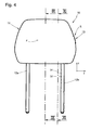
- the head abutment surface F is moved upward in the vertical direction z with respect to the home position (the direction z is in FIG Fig. 4 ).
- the adjustability of the cushion body 11 has the purpose to adjust the position of the cushion body 11 to the seating position of the seat occupant and in this way both to provide greater comfort, and to reduce the risk of injury.
- the locking device S prevents the cushion body 11 moves unintentionally from the set position.
- the locking device S is formed in the present embodiment as a locking device in the form of a form-Richtgesperres and can be moved between a locking position and a release position. A forward movement of the cushion body 11 in the direction of the end position is possible in the blocking position of the locking device S. For this purpose, a certain minimum force required for movement must be exceeded, which is necessary to overcome the spring force, which holds locking elements of the locking device in engagement.
- the cushion body 11 can be moved back from the set position only in the basic position in the direction x2 when a button 13 is actuated to adjust the locking device S in the release position. Once the button 13 is released again, the locking device S moves automatically in the locked position. A movement of the cushion body 11 in the direction x2 of the home position is not possible in the locked position of the locking device S.
- the locking device could be designed such that in the locking position neither a movement in the direction x1, nor a movement in the direction x2 is possible.
- the cushion body 11 is loaded by a restoring force in a manner not shown in the basic position. As soon as the locking device S is moved to the release position, the cushion body 11 is therefore moved by the restoring force in the basic position when no restoring force is exerted on the cushion body 11, which corresponds to the restoring force or greater.
- a base member 14 is fixed to end portions 15 of the support rods 12a and 12b.
- the base part 14 is plate-shaped and forms between the end portions 15 of the support rods 12a and 12b spanned plane.
- the base part 14 is formed as a sheet metal part, which by a punching-bending process was formed.
- the end portions 15 of the support rods 12a and 12b are fixedly connected to welded joints 32 to the base portion 14.
- links 16a and links 16b are mounted about a substantially horizontally disposed pivot axis a1 in the direction v1, v2 pivotally mounted on a fixed to the base member 14 axle member 33.
- the link 16a forms with the axle 33 a pivot joint G1a
- the link 16b forms with the axle 33 a pivot joint G1b.
- Each link 16a and 16b is formed approximately circular sector.
- the link 16a is provided on a radially remote from the pivot axis a1 end portion 20 with a toothing 21a
- the link 16b is provided on the radially remote from the pivot axis a1 end portion 20 with a toothing 21 b.
- the trained in the manner of a spur toothing teeth 21 a and 21 b are part of the locking device S and serve the already mentioned above Rastarretmaschine the cushion body 11 in different positions, which will be explained in more detail below.
- a front side 42 of the base part 14 is shown.
- the base part 14 is provided with recesses 38a and 38b. It can be seen that the handlebar 16 a, the recess 38 a and the handlebar 16 b, the recess 38 b of the base member 14 passes through.
- the recesses 38a and 38b allow a simple design of the base part 14 and thus also the construction of a cushion body 11, which has small dimensions. Due to the recesses 38a and 38b, the substantially planar formation of the base part is possible, which allows a rear wall 44 of the cushion support 37 to move close to the support rod ends 15. It is therefore possible to make the cushion body 11 narrow with respect to its dimensions parallel to the direction of movement x1, x2.
- Each link 16a and 16b includes a bearing seat 18 (see, eg Fig. 5 ), which is approximately circular cylindrical and is provided for the pivotable mounting of an axle region 41 of the cushion support 37.
- the axle area 41 is in Fig. 5 only hinted at.
- the bearing seat 18 is provided for mounting the axle portion 41 of the cushion body 11 with an opening 19.
- the links 16a and 16b pivot during movement of the cushion body 11 between the home position and the end position synchronously, so that longitudinal axes of both bearing seats 18 of the links 16a and 16b are aligned and form a pivot axis a3.
- the link 16a is for attaching a strut 23a (see, eg Fig. 8 ) provided with a bearing seat 22a.
- the link 16a forms with the strut 23a a pivot joint G5a with the pivot axis a5.
- the handlebar 16b For attachment of a strut 23b, the handlebar 16b on a bearing seat 22b.
- the link 16b forms with the strut 23b a pivot joint G5b with the pivot axis a5.
- the struts 23a and 23b can be pivoted by means of the pivot joints G5a and G5b relative to the links 16a and 16b in the direction o1, o2.
- an axle element 24 is fastened to the base part 14.
- a link 17 is pivotably mounted about a substantially horizontally arranged pivot axis a2 in pivot directions u1, u2.
- a formed on a bearing arm 26 of the lower arm 17 bearing seat 25 is penetrated by the axle 24.
- the link 17 forms with the axle 24 a pivot joint G2 with the pivot axis a2.
- the lower arm 17 is provided with two axle sections 27a and 27b, whose longitudinal axes are aligned with each other and form a pivot axis a4.
- the axle sections 27a and 27b form a bearing seat for supporting the cushion body 11.
- bearing receivers 40a and 40b form a bearing seat for the axle sections 27a and 27b.
- pad body 11 is pivotable in this manner relative to the handlebar 17 about the pivot axis a4 in pivot directions n1, n2.
- a fastening extension 28a for pivotally mounting the strut 23a and a fastening extension 28b for pivotally mounting the strut 23b is formed on the lower link 17.
- the attachment extension 28a forms with the strut 23a a pivot joint G6a with a pivot axis a6
- the attachment extension 28b forms with the strut 23b a pivot joint G6b with the same pivot axis a6.
- the struts 23a and 23b can be pivoted by means of the pivot joints G6a and G6b relative to the link 17 in the direction of q1, q2.
- the bearing arm 26 is disposed at an obtuse angle to the end portion 34 of the link 17.
- the link 17 extends from the axle 24 on a back 43 of the base member 14 and engages around a lower end portion 39 of the base member 14th
- the above-mentioned locking device S has a pivot lock 29 (see, eg Fig. 8 ), which is mounted on the shaft member 24 about the pivot axis a2 in the pivot directions u1 and u2 pivotally mounted on the base part 14.
- the pivoting catch 29 is loaded in a manner not shown by a restoring force in the pivoting direction u1 in the locked position.
- the button 13 which is part of an actuating device of the locking device S, the pivot lock 29 can be pivoted from the illustrated blocking position by a movement in the direction u2 in the release position, not shown.
- the actuation of the pivoting catch 29 by the button 13 is effected indirectly via a lever bridge 35.
- the lever bridge 35 is pivotally mounted in the pivoting directions w1 and w2 on the cushion body 11 and formed as a one-armed lever.
- a free end portion 36 of the lever bridge 35 is in any position of the cushion body 11 in contact with the pivot catch 29.
- the lever bridge 35 is loaded back from the pivot latch 29 and is pivoted upon actuation by the key 13 in the pivot direction w2, wherein the pivot lock 29 against her Resetting load in the direction of u2 in the Release position moves.
- the button 13 is released, the swivel catch 29, caused by the restoring force, can move back in the direction u1 into the blocking position and thereby moves the lever bridge 35 in the swivel direction w1.
- the swivel catch 29 has, as in Fig. 5 to see a toothing 30a, which cooperates with the toothing 21a of the link 16a, and a toothing 30b, which cooperates with the toothing 21b of the link 16b.
- the toothing 30a In the locking position, the toothing 30a is in engagement with the toothing 21a and the toothing 30b in engagement with the toothing 21b. In the release position of the swivel catch 29, the teeth 30a and 30b are disengaged from the teeth 21a and 21b.
- the toothings 30a and 30b of the swivel catch 29 form with the teeth 21a and 21b of the upper link 16a and 16b a form-directional locking.
- FIGS. 11 and 13 is attached to the cushion support 37 axle portion 41 in the bearing seat 18 of the handlebar 16b and in the corresponding, in the FIGS. 11 and 13 not shown in the Bearing seat 18 of the handlebar 16 a pivotally mounted.
- the axle region 41 forms with the handlebar 16a a pivot joint G3a with the pivot axis a3 and with the link 16b a pivot joint G3b with the same pivot axis a3.
- the axle portion 41 connects the links 16a and 16b.
- the cushion body 11 is pivotable in this manner relative to the links 16a, 16b about the pivot axis a4 in pivoting directions m1, m2.
- the axle sections 27a and 27b of the lower link 17 (in the Fig. 11 and 12 If only the axle section 27a is shown), this forms a bearing seat for the complementarily designed bearing receivers 40a and 40b formed on the cushion support 37.
- the axle portion 27a forms with the bearing receptacle 40a a pivot joint G4a (only hinted at Fig. 7 shown), the axle portion 27b forms with the bearing receptacle 40b a pivot joint G4b.
- the pivot joints G4a and G4b have the same pivot axis a4.
- the opening 19 has a height H which is smaller than the diameter D of the bearing seat 18 and the outer diameter of the axle portion 41, which corresponds approximately to the diameter D.
- the axle region 41 is provided with mutually parallel side flattenings formed on both sides, the outer surfaces of which have a spacing which corresponds approximately to the height H or is somewhat smaller.
- the links 16a and 16b may be used to mount the cushion body 11 with respect to the in Fig. 11 be moved position shown in a pivoted about 90 ° position.
- the axle region 41 can then be easily assembled through the openings 19 in the bearing seats 18 of the links 16a and 16b.
- a bolt prevents movement of the handlebars 16a and 16b in the assembled position in the fully assembled headrest.
- the axle sections 27a and 27b are mounted in the bearing receivers 40a and 40b.
- the pivot axes a1, a2, a3, a4, a5 and a6 are parallel to each other and parallel to an in Fig. 4 arranged y-axis arranged.
- the pivot axes a1 and a2 are in the z direction spaced apart.
- the links 16a and 16b, the handlebar 17, the base 14 and the cushion support 37 form a coupling mechanism.
- Each link 16a and 16b forms with the link 17, the base part 14 and the cushion support 37 is a four-bar linkage, which is part of the linkage.
- the link 16b is pivotally connected to the lower link 17 by means of the strut 23b.
- the handlebar 16a (in the Fig. 11 and 12 not shown - see eg Fig. 8 ) is pivotally connected by means of the strut 23 a with the lower arm 17.
- the link 16a, the strut 23a, the base part 14 and the link 17 form a four-bar linkage, which is part of the linkage.
- the link 16b, the strut 23b, the base member 14 and the handlebar 17 also form a four-bar linkage, which is also part of the linkage.
- Each pivotal position of the links 16a and 16b and of the link 17 relative to the base part 14 is associated with a specific position of the cushion body 11.
- Fig. 9 and 11a is the cushion body 11, which forms part of the linkage arranged in the basic position.
- the Fig. 10 and 12 show the cushion body 11 in the end position in which the links 16a, 16b are pivoted in direction v1 about the pivot axis a1 and the link 17 in the direction u1 about the pivot axis a2 by a certain angle with respect to the basic position of the cushion body 11.
- a movement of the locking device S in the release position of the cushion body 11 can be moved back from the end position to the home position or in intermediate positions, wherein in the home position the handlebars 16a, 16b in the direction v2 and the handlebar 17 in the direction u2 with respect to the end position of the cushion body 11 are pivoted.
- a force acting on the cushion support 37 causes in the links 16a and 16b a first moment about the pivot axis a1 in the direction v2 and in the link 17 a moment about the pivot axis a2 in the direction u2.
- Forces acting on the links 16a, 16b can be transmitted to the base part 14 via the G1a and G1b as well as via the teeth 21a and 21b when the locking device S is in the locked position.
- a force acting on the handlebar 17 may be e.g. be transmitted in half over the strut 23a on the handlebar 16a and half over the strut 23b on the handlebar 16b.
- the force transmitted by the link 17 to the links 16a and 16b by means of the struts 23a and 23b causes in the links 16a and 16b a second moment about the pivot axis a1 in the direction v1, which counteracts the first moment.
Landscapes
- Engineering & Computer Science (AREA)
- Aviation & Aerospace Engineering (AREA)
- Transportation (AREA)
- Mechanical Engineering (AREA)
- Seats For Vehicles (AREA)
- Chair Legs, Seat Parts, And Backrests (AREA)
Abstract
Description
- Die Erfindung betrifft eine Kopfstütze gemäß dem Oberbegriff des Anspruchs 1.
- Eine solche Kopfstütze ist beschrieben in der
DE 199 51 966 B4 . Bei der Kopfstütze ist ein Polsterteil mit wenigstens zwei im Abstand voneinander angeordneten Schwenkhebeln zwischen einer Ruhelage und einer Wirklage verlagerbar und in der Wirklage arretierbar. Die Arretierung erfolgt mittels eines an einem tragstangenfesten Grundteil gehaltenen Schwenkteils. Das Schwenkteil ist mit einem Fortsatz ausgestattet, welcher in Kontakt mit dem Polsterteil steht und eine Rückbewegung des Polsterteils verhindert. Das Schwenkteil kann mit einer Rastvorrichtung in unterschiedlichen Positionen arretiert werden, wobei die Positionen des Schwenkteils unterschiedlichen Positionen des Kopfanlageteils zugeordnet sind. - In der
DE 102 02 598 B4 ist eine Kopfstütze beschrieben, die ein Grundteil sowie ein gelenkig an dem Grundteil gelagertes Prallelement umfasst. Das Prallelement ist relativ zu dem Grundteil bewegbar und mittels Sperrmitteln in der eingestellten Stellung festsetzbar. Die Sperrmittel sind erfindungsgemäß von einer Schlingfeder gebildet, mittels welcher das Prallelement durch Reibschluss in der eingestellten Stellung haltbar ist. - In der
DE 103 48 939 B3 ist eine Kopfstütze offenbart, die ein tragstangenfest gehaltenes Grundteil sowie ein Kopfanlageteil aufweist, welches mit einem Hebelsystem an dem Grundteil gelagert ist. Das Kopfanlageteil umfasst ein Langloch, in welchem ein Zapfen geführt ist, der einem unteren Hebel des Hebelsystems zugeordnet ist. Auf diese Weise sind unterschiedliche Bewegungsabläufe zwischen Prallelement und Grundteil möglich. - In der
DE 203 21 462 U1 ist eine Kopfstütze beschrieben, wobei ein Kopfanlageteil mit oberen und unteren Lenkern an einem Basisteil bewegbar gelagert ist. Im Crashfall kann das Kopfanlageteil aus einer Grundposition nach vorne in eine durch eine Crashsperre nach hinten gesperrte Crashstellung ausfahren. Ein Rastmechanismus erlaubt darüber hinaus das Einstellen des Kopfanlageteils in unterschiedliche Komfortstellungen. Aus der jeweils eingestellten Position kann das Kopfanlageteil durch Überwindung der Haltekraft einer Rastfeder in eine andere Position bewegt werden. - Ausgehend von dem letztgenannten Stand der Technik ist es Aufgabe der Erfindung, eine Kopfstütze zu schaffen, die dem Sitzinsassen das Einstellen des Kopfanlageteils in unterschiedliche Positionen ermöglicht. Des Weiteren ist es Aufgabe der Erfindung, die Kopfstütze so auszubilden, dass das Kopfanlageteil auch bei hohen Belastungen der von dem Insassen auf die Kopfanlagefläche aufgebrachten Kraft standhält. Zudem ist es Aufgabe der Erfindung, eine Kopfstütze zu schaffen, die in Bezug auf die Herstellbarkeit vorteilhaft ist. Des Weiteren ist es Aufgabe der Erfindung, eine Kopfstütze zu schaffen, die einen geringen Platzbedarf sowie ein geringes Gewicht aufweist.
- Die Aufgabe wird gemäß einem ersten Aspekt der Erfindung gelöst durch eine Kopfstütze mit den Merkmalen des Anspruchs 1.
- Erfindungsgemäß weist die Kopfstütze ein tragstangenfestes Basisteil sowie eine an einem Polsterträger ausgebildete Kopfanlagefläche auf. Der Polsterträger ist relativ zu dem Basisteil bewegbar an dem Basisteil gelagert. Der Polsterträger ist mindestens einem ersten Verbindungselement eines Koppelgetriebes zugeordnet. Das erste Verbindungselement kann z.B. von dem Polsterträger gebildet sein. Das erste Verbindungselement bildet mit wenigstens einem ersten Lenker und wenigstens einem zweiten Lenker Schwenkgelenke.
- Der erste Lenker und der zweite Lenker sind schwenkbar an dem Basisteil befestigt. Sowohl das zwischen dem ersten Lenker und dem Basisteil ausgebildete Schwenkgelenk, als auch das zwischen dem zweiten Lenker und dem Basisteil ausgebildete Schwenkgelenk sind relativ zu dem Basisteil fest angeordnet. Außerdem sind sowohl das zwischen dem ersten Lenker und dem ersten Verbindungselement ausgebildete Schwenkgelenk als auch das zwischen dem zweiten Lenker und dem ersten Verbindungselement ausgebildete Schwenkgelenk bezüglich dem ersten Verbindungselement fest angeordnet. Das erste Verbindungselement, der erste Lenker, der zweite Lenker und das Basisteil bilden ein Koppelgetriebe in Form eines Viergelenks, wobei das Basisteil tragstangenfest angeordnet ist.
- Die Kopfstütze kann einen oder mehrere erste Lenker sowie einen oder mehrere zweite Lenker aufweisen. Jeder erste Lenker ist bezüglich des Basisteils z.B. um dieselbe geometrische erste Schwenkachse schwenkbar. Jeder zweite Lenker ist bezüglich des Basisteils z.B. um dieselbe geometrische zweite Schwenkachse schwenkbar.
- Der wenigstens eine erste Lenker ist erfindungsgemäß durch mindestens ein zweites Verbindungselement mit dem mindestens einen zweiten Lenker verbunden. Das zweite Verbindungselement bildet sowohl mit dem ersten Lenker als auch mit dem zweiten Lenker ein Schwenkgelenk. Z. B. können zwei erste Lenker vorhanden sein, die jeweils mit einem zweiten Verbindungselement ein Schwenkgelenk bilden. Jedes zweite Verbindungselement kann außerdem mit einem zweiten Lenker ein Schwenkgelenk bilden. Von dem Basisteil, dem ersten Lenker, dem zweiten Lenker und dem zweiten Verbindungselement wird somit ein zweites Viergelenk gebildet.
- Bei einer Belastung können Kräfte über das zweite Verbindungselement zwischen dem ersten Lenker und dem zweiten Lenker übertragen werden. Insbesondere kann eine Verformung von Teilen des Koppelgetriebes verhindert werden, wenn bei einer starken Belastung der Kopfanlagefläche große Hebelkräfte auftreten. Z.B. sind mittels des ersten Lenkers sowohl über das zwischen dem Basisteil und dem ersten Lenker ausgebildete Schwenkgelenk, als auch über eine den ersten Lenker in einer bestimmten Position arretierende Sperrvorrichtung Kräfte auf das Basisteil übertragbar. Von dem zweiten Lenker sind Kräfte über das gemeinsame Schwenkgelenk auf das Basisteil übertragbar. Aufgrund des zweiten Verbindungselements der erfindungsgemäßen Kopfstütze kann ein Kräfteausgleich von dem zweiten Hebel auf den ersten Hebel stattfinden, welcher einer Verformung des Polsterträgers und eine Überlastung der Elemente des Koppelgetriebes verhindert.
- Mittels des zweiten Verbindungselements ist es möglich die bei einer Belastung durch den Sitzinsassen auf den Polsterträger aufgebrachte Kraft von dem zweiten Lenker derart in den ersten Lenker einzuleiten, dass ein Gegenmoment zu der unmittelbar von dem ersten Verbindungselement in den ersten Lenker eingeleiteten Kraft entsteht. Hierdurch können z.B. die auf die Sperrvorrichtung wirkenden Kräfte gemindert werden. Bei der Kopfstütze mit den erfindungsgemäßen Merkmalen ist ein Kräfteausgleich zwischen den Teilen des Koppelgetriebes möglich, welcher die Überlastung einzelner Teile verhindert. Mittels des zweiten, überlagerten Viergelenks ist z.B. die Ausbildung des ersten Lenkers und des zweiten Lenkers als Kunststoffteil möglich.
- Außerdem ist z.B. eine Kräfteaufteilung möglich, wenn mehrere zweite Verbindungselemente vorhanden sind. Weist die Kopfstütze z.B. zwei erste Lenker und einen zweiten Lenker auf, kann ein Teil der von dem ersten Verbindungselement in den zweiten Lenker eingeleiteten Kräfte mittels mehrerer zweiter Verbindungselemente in beide erste Lenker eingeleitet werden, wobei eine Kräfteaufteilung stattfindet.
- Das zweite Verbindungselement kann z.B. von einer Strebe gebildet sein, mittels welcher Druckkräfte sowie Zugkräfte zwischen dem ersten Lenker und dem zweiten Lenker übertragbar sind.
- Gemäß einer Ausführungsform der Erfindung ist eine Bewegung des ersten Verbindungselements in der jeweils eingestellten Position mittels einer Sperrvorrichtung verhinderbar. Die Sperrvorrichtung ist zwischen einer Sperrposition und eine Löseposition bewegbar. In der Sperrposition wird eine Bewegung des ersten Verbindungselements in wenigstens eine Bewegungsrichtung des ersten Verbindungselements verhindert. In der Löseposition ist das erste Verbindungselement zwischen der Grundposition und der Endposition bewegbar.
- Gemäß einer weiteren Ausführungsform ist die Sperrvorrichtung von einem Form-Richtgesperre gebildet. Auf diese Weise ist es z.B. möglich, das erste Verbindungselement in eine erste Bewegungsrichtung aus der jeweils eingestellten Position zu bewegen, wohingegen die Bewegung in eine entgegen gesetzte Bewegungsrichtung von dem Form-Richtgesperre verhindert wird, wenn sich die Sperrvorrichtung in der Sperrposition befindet. Z.B. kann das erste Verbindungselement in der Sperrposition der Sperrvorrichtung in Richtung Endposition bewegbar sein, während eine Bewegung in Richtung Grundposition von der Sperrvorrichtung verhindert wird.
- Einer weiteren Ausführungsform gemäß umfasst die Sperrvorrichtung dem Basisteil zugeordnete erste Sperrmittel, welche lösbar mit zweiten Sperrmitteln in Eingriff bewegbar sind. Die Sperrvorrichtung kann z.B. bei einem Eingriff der ersten und der zweiten Sperrmittel die Bewegung des ersten Verbindungselements in wenigstens eine Richtung verhindern. Die zweiten Sperrmittel sind z.B. einem relativ zu dem Basisteil bewegbaren Teil des Koppelgetriebes, z.B. dem ersten Lenker, zugeordnet. Die ersten Sperrmittel sind z.B. bewegbar an dem Basisteil gelagert. Die ersten und/oder die zweiten Sperrmittel können z.B. zwischen der Sperrposition und der Löseposition bewegbar sein. Die ersten Sperrmittel und die zweiten Sperrmittel können z.B. kraftschlüssig und/oder formschlüssig in Eingriff bringbar sein.
- Gemäß einer weiteren Ausführungsform sind die ersten Sperrmittel und/oder die zweiten Sperrmittel von einem schwenkbaren Hebel gebildet. Der Hebel kann z.B. auf einer basisteilfesten Schwenkachse gelagert sein. Durch eine geringe Bewegung können die ersten Sperrmittel und die zweiten Sperrmittel auf die Weise in Eingriff oder außer Eingriff bewegt werden. Mittels dieser Ausführungsform ist eine Ausbildung der Sperrvorrichtung möglich, die einen geringen Platzbedarf erfordert.
- Gemäß einer weiteren Ausführungsform ist die Sperrvorrichtung mittels einer Betätigungsvorrichtung zwischen der Sperrposition und der Löseposition bewegbar. Z.B. kann die Sperrvorrichtung in die Sperrposition rückstellbelastet sein. Mittels der Betätigungsvorrichtung kann z.B. die Sperrvorrichtung aus der Sperrposition in die Löseposition bewegt werden.
- Einer weiteren Ausgestaltung der Erfindung gemäß weist die Betätigungsvorrichtung eine Übertragungsvorrichtung auf, mittels welcher eine Bewegung eines dem Polsterträger zugeordneten Bedienelements auf das erste oder das zweite Sperrmittel übertragbar ist. Die Übertragung kann mittels der Übertragungsvorrichtung in jeder Position des Polsterträgers erfolgen.
- Die Übertragungsvorrichtung weist z.B. einen schwenkbaren Hebel auf, der über einen Betätigungselement, wie z.B. eine Taste, verschwenkbar ist. Das Betätigungselement ist z.B. an dem Polsterträger befestigt. Ein Hebelarm des Hebels ist z.B. in jeder Position des Polsterträgers des Koppelgetriebes mit einem an dem Basisteil gelagerten Sperrmittel in Kontakt bewegbar. Auf diese Weise ist es möglich, die Bewegung des an dem Polsterträger befestigten Betätigungselements in jeder Position des Polsterträgers auf die Sperrvorrichtung zu übertragen.
- Die oben genannte Aufgabe wird gemäß einem zweiten Aspekt der Erfindung gelöst durch eine Kopfstütze mit den Merkmalen des Anspruches 8.
- Hinsichtlich der Merkmale des Oberbegriffs des Anspruchs 8 wird Bezug genommen auf die Ausführungen zu dem ersten Aspekt der Erfindung.
- Das Basisteil ist fest mit zwei Tragstangenenden verbunden. Das Basisteil ist z.B. im Wesentlichen eben ausgebildet und erstreckt sich z.B. plattenförmig zwischen den Tragstangen. Erfindungsgemäß weist das Basisteil wenigstens eine Aussparung auf, welche wenigstens von einem Teilbereich des ersten Lenkers und / oder des zweiten Lenkers durchgreifbar ist. Darüber hinaus kann die Aussparung von anderen Teilen des Koppelgetriebes durchgreifbar sein. Z.B. kann an dem ersten Lenker und dem zweiten Lenker ein zweites Verbindungselement schwenkbar gehalten sein, durch welches ein zweites Viergelenk ausgebildet ist. Die Aussparung kann z.B. von dem zweiten Verbindungselement durchgreifbar sein.
- Mit den erfindungsgemäßen Merkmalen kann die Kopfstütze mit einem geringen Bauraum ausgebildet werden. Die Aussparungen in dem Basisteil erlauben eine im Wesentlichen ebene Ausbildung des Basisteils. Auf diese Weise ist es möglich, eine hintere Wand des Polsterträgers in der Endposition des Polsterträgers nahe an die Tragstangenenden heranzubewegen. Der Polsterträger kann daher mit geringen Abmessungen ausgebildet sein. Insbesondere, wenn das Basisteil aus Metall, z.B. aus Blech gebildet ist, kann es große Kräfte aufnehmen. Die erfindungsgemäßen Merkmale machen zudem eine aufwändige Formgebung des Basisteils überflüssig.
- Gemäß einer Ausführungsform ist das Basisteil als Metallteil, insbesondere als Stanzbiegeteil, ausgebildet. Das Basisteil ist dann in der Lage, hohe Kräfte aufzunehmen und lässt sich vorteilhaft fertigen. Bei gleicher Festigkeit weist das Basisteil bei dieser Ausführungsform z.B. verglichen mit einem Kunststoffteil ein geringes Gewicht auf.
- Einer weiteren Ausführungsform gemäß sind der erste Lenker und /oder der zweite Lenker etwa kreissektorförmig ausgebildet. Entlang einer von der Schwenkachse beabstandeten Kreisbahn mit der Schwenkachse als Kreisradius können gemäß dieser Ausführungsform Sperrmittel einer Sperrvorrichtung ausgebildet sein, die in jeder Position des Lenkers eine Arretierung des Lenkers in wenigstens einer Bewegungsrichtung ermöglichen. Indem die zweiten Sperrmittel von der Schwenkachse beabstandet sind, wirkt die Sperrvorrichtung mit einem großen Hebelarm auf den Lenker. Die Sperrmittel können z.B. nach Art einer Stirnverzahnung an dem ersten und / oder dem zweiten Lenker ausgebildet sein.
- Weitere Vorteile ergeben sich anhand eines in den Figuren dargestellten Ausführungsbeispiels. Es zeigen:
- Fig.1
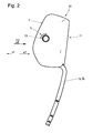
- eine schematische perspektivische Darstellung der erfindungsgemäßem Kopfstütze,
- Fig. 2
- eine schematische Seitenansicht der Kopfstütze, wobei ein Polsterkörper in einer Grundposition angeordnet ist,
- Fig. 3
- die Kopfstütze in Anlehnung an
Fig. 2 , wobei der Polsterkörper in einer Endposition angeordnet ist, - Fig. 4
- eine schematische Frontansicht der Kopfstütze gemäß Ansichtspfeil IV in
Fig. 2 , - Fig. 5
- eine schematische perspektivische Darstellung der Kopfstütze in der Grundposition, wobei ein Polsterkörper nicht dargestellt ist,
- Fig. 6
- eine schematische perspektivische rückwärtige Ansicht der Kopfstütze in der Grundposition gemäß
Fig. 5 , - Fig. 7
- die Kopfstütze in Anlehnung an
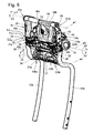
Fig. 5 in der Endposition, - Fig. 8
- die Kopfstütze in Anlehnung an
Fig. 6 in der Endposition, - Fig. 9
- eine Schnittdarstellung gemäß Schnittlinie IX-IX in
Fig. 4 , - Fig. 10
- die Kopfstütze in Anlehnung an
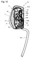
Fig. 9 , wobei der Polsterkörper in der Endposition angeordnet ist, - Fig. 11
- eine Schnittdarstellung gemäß Schnittlinie XI-XI in
Fig. 4 , - Fig. 12
- die Kopfstütze in Anlehnung an
Fig. 11 , wobei die Kopfanlagefläche in der Endposition angeordnet ist und - Fig. 13
- eine Ausschnittdarstellung gemäß Ausschnittlinie XIII in
Fig. 11 . - Eine Kopfstütze insgesamt wird in den Zeichnungen mit dem Bezugszeichen 10 bezeichnet. Gleiche Bezugszeichen in den unterschiedlichen Figuren bezeichnen auch bei Hinzufügung oder Weglassen von kleinen Buchstaben entsprechende Teile.
- Gemäß
Fig. 1 umfasst die Kopfstütze 10 einen von einem Polster P sowie einem Polsterträger 37 gebildeten Polsterkörper 11, der auf Tragstangen 12a und 12b gelagert ist. Die Tragstangen 12a und 12b sind jeweils in einem rückenlehnenfesten, nicht dargestellten Lager höhenverstellbar gelagert und können in unterschiedlichen Höhenpositionen mittels einer Arretiervorrichtung arretiert werden. Die Tragstange 12b weist mehrere Kerben 31 (inFig. 4 dargestellt) auf, die Teil der Arretiervorrichtung sind. Die Kerben 31 wirken in nicht dargestellter Weise mit einem Rastmittel des rückenlehnenseitigen Lagers zusammen, um die Kopfstütze 10 in der eingestellten Höhenposition zu arretieren. Die Arretierung kann in bekannter Weise durch Betätigung einer Handhabe gelöst werden, um eine Höhenverstellung der Kopfstütze 10 vornehmen zu können. - Der Polsterkörper 11 ist zwischen einer in
Fig. 2 dargestellten Grundposition und einer inFig. 3 dargestellten Endposition verstellbar. Darüber hinaus kann der Polsterkörper 10 in nicht dargestellte Positionen verstellt werden, die zwischen der Grundposition und der Endposition liegen. In der Endposition ist eine Kopfanlagefläche F des Polsterkörpers 11 bezüglich der Grundposition näher in horizontaler Richtung x1 zu dem Fahrzeuginsassen hin bewegt. Außerdem ist die Kopfanlagefläche F in der Endposition bezüglich der Grundposition nach oben in die vertikale Richtung z bewegt (die Richtung z ist inFig. 4 ). Die Verstellbarkeit des Polsterkörpers 11 hat den Zweck, die Position des Polsterkörpers 11 an die Sitzposition des Sitzinsassen anzupassen und auf diese Weise sowohl einen größeren Komfort zu bieten, als auch die Verletzungsgefahr zu mindern. - Mit einer Sperrvorrichtung S wird verhindert, dass der Polsterkörper 11 sich ungewollt aus der eingestellten Position bewegt. Die Sperrvorrichtung S ist in dem vorliegenden Ausführungsbeispiel als Rastvorrichtung in Form eines Form- Richtgesperres ausgebildet und kann zwischen einer Sperrposition und einer Löseposition bewegt werden. Eine Vorwärtsbewegung des Polsterkörpers 11 in Richtung der Endposition ist in der Sperrposition der Sperrvorrichtung S möglich. Hierzu muss eine bestimmte zur Bewegung erforderliche Mindestkraft überschritten werden, die zur Überwindung der Federkraft nötig ist, welche Rastelemente der Rastvorrichtung in Eingriff hält.
- Der Polsterkörper 11 kann aus der eingestellten Position erst dann in die Grundposition in Richtung x2 zurückbewegt werden, wenn eine Taste 13 betätigt wird, um die Sperrvorrichtung S in die Löseposition zu verstellen. Sobald die Taste 13 wieder gelöst ist, bewegt sich die Sperrvorrichtung S automatisch in die Sperrposition. Eine Bewegung des Polsterkörpers 11 in Richtung x2 der Grundposition ist in der Sperrposition der Sperrvorrichtung S nicht möglich.
- Gemäß einer alternativen, nicht dargestellten Ausführung könnte die Sperrvorrichtung derart ausgebildet sein, dass in der Sperrposition weder eine Bewegung in Richtung x1, noch eine Bewegung in Richtung x2 möglich ist.
- Der Polsterkörper 11 ist durch eine Rückstellkraft in nicht dargestellter Weise in die Grundposition belastet. Sobald die Sperrvorrichtung S in die Löseposition verstellt ist, wird der Polsterkörper 11 daher von der Rückstellkraft in die Grundposition bewegt, wenn keine der Rückstellkraft entgegen gerichtete Kraft auf den Polsterkörper 11 ausgeübt wird, welche der Rückstellkraft entspricht oder größer ist.
- In den
Fig. 5 bis 8 ist die Kopfstütze 10 ohne Polsterkörper 11 dargestellt. Ein Basisteil 14 ist an Endbereichen 15 der Tragstangen 12a und 12b befestigt. Das Basisteil 14 ist plattenförmig ausgebildet und bildet eine zwischen den Endbereichen 15 der Tragstangen 12a und 12b aufgespannte Ebene. Im vorliegenden Fall ist das Basisteil 14 als Blechformteil ausgebildet, welches durch einen Stanz-Biegevorgang geformt wurde. Die Endbereiche 15 der Tragstangen 12a und 12b sind mit Schweißverbindungen 32 mit dem Basisteil 14 fest verbunden. - Zur Lagerung des Polsterkörpers 11 vorgesehene Lenker 16a und Lenker 16b sind um eine im Wesentlichen horizontal angeordnete Schwenkachse a1 in Richtung v1, v2 schwenkbar auf einem fest mit dem Basisteil 14 verbundenen Achselement 33 gelagert. Der Lenker 16a bildet mit dem Achselement 33 ein Schwenkgelenk G1a, der Lenker 16b bildet mit dem Achselement 33 ein Schwenkgelenk G1b.
- Jeder Lenker 16a und 16b ist etwa kreissektorförmig ausgebildet. Der Lenker 16a ist an einem radial von der Schwenkachse a1 abgewandten Endbereich 20 mit einer Verzahnung 21a, der Lenker 16b ist an dem radial von der Schwenkachse a1 abgewandten Endbereich 20 mit einer Verzahnung 21 b versehen. Die nach Art einer Stirnverzahnung ausgebildeten Verzahnungen 21 a und 21 b sind Teil der Sperrvorrichtung S und dienen der bereits oben erwähnten Rastarretierung des Polsterkörpers 11 in unterschiedlichen Positionen, was weiter unten noch näher erläutert wird.
- In
Fig. 5 ist eine Vorderseite 42 des Basisteils 14 dargestellt. Das Basisteil 14 ist mit Aussparungen 38a und 38b versehen. Es ist erkennbar, dass der Lenker 16a die Aussparung 38a und der Lenker 16b die Aussparung 38b des Basisteils 14 durchgreift. Die Aussparungen 38a und 38b erlauben eine einfache Gestaltung des Basisteils 14 und somit auch die Konstruktion eines Polsterkörpers 11, der geringe Abmessungen aufweist. Aufgrund der Aussparungen 38a und 38b ist die im Wesentlichen ebene Ausbildung des Basisteils möglich, welche es erlaubt, eine hintere Wand 44 des Polsterträgers 37 nahe an die Tragstangenenden 15 heranzubewegen. Es ist daher möglich, den Polsterkörper 11 bezüglich seiner Ausmaße parallel zu der Bewegungsrichtung x1, x2 schmal auszubilden. - Jeder Lenker 16a und 16b umfasst einen Lagersitz 18 (siehe z.B.
Fig. 5 ), der etwa kreiszylindrisch ausgebildet und zur schwenkbaren Lagerung eines Achsbereichs 41 des Polsterträgers 37 vorgesehen ist. Der Achsbereich 41 ist inFig. 5 lediglich andeutungsweise dargestellt. Der Lagersitz 18 ist zur Montage des Achsbereichs 41 des Polsterkörpers 11 mit einer Öffnung 19 versehen. - Die Lenker 16a und 16b schwenken während einer Bewegung des Polsterkörpers 11 zwischen der Grundposition und der Endposition synchron, so dass Längsachsen beider Lagersitze 18 der Lenker 16a und 16b fluchten und eine Schwenkachse a3 ausbilden.
- Der Lenker 16a ist zur Befestigung einer Strebe 23a (siehe z.B.
Fig. 8 ) mit einem Lagersitz 22a versehen. Der Lenker 16a bildet mit der Strebe 23a ein Schwenkgelenk G5a mit der Schwenkachse a5. Zur Befestigung einer Strebe 23b weist der Lenker 16b einen Lagersitz 22b auf. Der Lenker 16b bildet mit der Strebe 23b ein Schwenkgelenk G5b mit der Schwenkachse a5. Die Streben 23a und 23b können mittels der Schwenkgelenke G5a und G5b relativ zu den Lenkern 16a und 16b in Richtung o1, o2 geschwenkt werden. - Z.B. in
Fig. 8 ist erkennbar, dass an dem Basisteil 14 ein Achselement 24 befestigt ist. An dem Achselement 24 ist ein Lenker 17 um eine im Wesentlichen horizontal angeordnete Schwenkachse a2 in Schwenkrichtungen u1, u2 schwenkbar gelagert. Ein an einem Lagerarm 26 des unteren Lenkers 17 ausgebildeter Lagersitz 25 wird von dem Achselement 24 durchgriffen. Der Lenker 17 bildet mit dem Achselement 24 ein Schwenkgelenk G2 mit der Schwenkachse a2. - An einem radial von der Schwenkachse a2 entfernten Endbereich 34 (siehe z.B.
Fig. 7 ) ist der untere Lenker 17 mit zwei Achsabschnitten 27a und 27b versehen, deren Längsachsen miteinander fluchten und eine Schwenkachse a4 bilden. Die Achsabschnitte 27a und 27b bilden einen Lagersitz zur Lagerung des Polsterkörpers 11. InFig. 7 durch eine Strichlinie lediglich andeutungsweise dargestellte Lageraufnahmen 40a und 40b bilden einen Lagersitz für die Achsabschnitte 27a und 27b. Der inFig. 7 nicht dargestellte Polsterkörper 11 ist auf diese Weise relativ zu dem Lenker 17 um die Schwenkachse a4 in Schwenkrichtungen n1,n2 schwenkbar. - An dem unteren Lenker 17 ist ein Befestigungsfortsatz 28a zur schwenkbaren Befestigung der Strebe 23a sowie ein Befestigungsfortsatz 28b zur schwenkbaren Befestigung der Strebe 23b ausgebildet. Der Befestigungsfortsatz 28a bildet mit der Strebe 23a ein Schwenkgelenk G6a mit einer Schwenkachse a6, der Befestigungsfortsatz 28b bildet mit der Strebe 23b ein Schwenkgelenk G6b mit der gleichen Schwenkachse a6. Die Streben 23a und 23b können mittels der Schwenkgelenke G6a und G6b relativ zu dem Lenker 17 in Richtung q1, q2 geschwenkt werden. Der Lagerarm 26 ist in einem stumpfen Winkel zu dem Endbereich 34 des Lenkers 17 angeordnet. Der Lenker 17 erstreckt sich von dem Achselement 24 auf einer Rückseite 43 des Basisteils 14 und umgreift einen unteren Endbereich 39 des Basisteils 14.
- Zur Rastarretierung des Polsterkörpers 11 in unterschiedlichen Positionen weist die oben erwähnte Sperrvorrichtung S eine Schwenkraste 29 auf (siehe z.B.
Fig. 8 ), welche auf dem Achselement 24 um die Schwenkachse a2 in die Schwenkrichtungen u1 und u2 schwenkbar an dem Basisteil 14 gelagert ist. Die Schwenkraste 29 ist in nicht dargestellter Weise von einer Rückstellkraft in Schwenkrichtung u1 in die Sperrposition belastet. Durch Betätigung der Taste 13, die Bestandteil einer Betätigungsvorrichtung der Sperrvorrichtung S ist, kann die Schwenkraste 29 aus der dargestellten Sperrposition durch eine Bewegung in Richtung u2 in die nicht dargestellte Löseposition geschwenkt werden. - Die Betätigung der Schwenkraste 29 durch die Taste 13 erfolgt mittelbar über eine Hebelbrücke 35. Die Hebelbrücke 35 ist in die Schwenkrichtungen w1 und w2 schwenkbar an dem Polsterkörper 11 gelagert und als einarmiger Hebel ausgebildet. Ein freier Endbereich 36 der Hebelbrücke 35 steht in jeder Position des Polsterkörpers 11 in Kontakt mit der Schwenkraste 29. Die Hebelbrücke 35 ist von der Schwenkraste 29 rückstellbelastet und wird bei Betätigung durch die Taste 13 in Schwenkrichtung w2 verschwenkt, wobei sie die Schwenkraste 29 entgegen ihrer Rückstellbelastung in Richtung u2 in die Löseposition bewegt. Bei gelöster Taste 13 kann sich die Schwenkraste 29, von der Rückstellkraft veranlasst, in Richtung u1 in die Sperrposition zurückbewegen und bewegt dabei die Hebelbrücke 35 in Schwenkrichtung w1.
- Die Schwenkraste 29 weist, wie z.B. in
Fig. 5 zu sehen, eine Verzahnung 30a auf, die mit der Verzahnung 21a des Lenkers 16a zusammenwirkt, sowie eine Verzahnung 30b, die mit der Verzahnung 21 b des Lenkers 16b zusammenwirkt. - In der Sperrposition befindet sich die Verzahnung 30a in Eingriff mit der Verzahnung 21a und die Verzahnung 30b in Eingriff mit der Verzahnung 21 b. In der Löseposition der Schwenkraste 29 befinden sich die Verzahnungen 30a und 30b mit den Verzahnungen 21a und 21b außer Eingriff.
- Die Verzahnungen 30a und 30b der Schwenkraste 29 bilden mit den Verzahnungen 21a und 21b der oberen Lenker 16a und 16b ein Form- Richtgesperre. In der in
Fig. 11 dargestellten Sperrposition der Sperrvorrichtung S sind die Lenker 16a und 16b und damit das gesamte Koppelgetriebe aus der Grundposition nach vorne in Richtung v1 schwenkbar. Ein Zurückbewegen der Lenker 16a und 16b z.B. aus der inFig. 12 dargestellten Endposition in Richtung v2 wird jedoch von der Sperrvorrichtung S verhindert, wenn sie sich in der Sperrposition befindet. - Durch Betätigen der Taste 13 wird die Schwenkraste 29 entgegen ihrer Federbelastung aus dem Eingriff mit der Verzahnung 21 bewegt. Im Anschluss kann der Polsterkörper 11 in Richtung x2 der Grundposition zurückbewegt werden. Sobald die Taste 13 wieder freigegeben wird, bewegt sich die Schwenkraste 29 in den Eingriff mit den oberen Lenkern 16.
- Gemäß der
Fig. 11 und 13 ist der an dem Polsterträger 37 befestigte Achsbereich 41 in dem Lagersitz 18 des Lenkers 16b und in entsprechender, in denFig. 11 und 13 nicht dargestellter Weise in dem Lagersitz 18 des Lenkers 16a schwenkbar gelagert. Der Achsbereich 41 bildet mit dem Lenker 16a ein Schwenkgelenk G3a mit der Schwenkachse a3 und mit dem Lenker 16b ein Schwenkgelenk G3b mit der gleichen Schwenkachse a3. Der Achsbereich 41 verbindet die Lenker 16a und 16b. Der Polsterkörper 11 ist auf diese Weise relativ zu den Lenkern 16a, 16b um die Schwenkachse a4 in Schwenkrichtungen m1 ,m2 schwenkbar. - Die Achsabschnitte 27a und 27b des unteren Lenkers 17 (in den
Fig. 11 und12 ist lediglich der Achsabschnitt 27a dargestellt) bilden einen Lagersitz für die komplementär ausgebildeten an dem Polsterträger 37 ausgebildeten Lageraufnahmen 40a und 40b. Der Achsabschnitt 27a bildet mit der Lageraufnahme 40a ein Schwenkgelenk G4a (lediglich andeutungsweise inFig. 7 dargestellt), der Achsabschnitt 27b bildet mit der Lageraufnahme 40b ein Schwenkgelenk G4b. Die Schwenkgelenke G4a und G4b weisen dieselbe Schwenkachse a4 auf. - Gemäß
Fig. 13 weist die Öffnung 19 eine Höhe H auf, die geringer ist, als der Durchmesser D des Lagersitzes 18 und dem Außendurchmesser des Achsbereichs 41, der etwa dem Durchmesser D entspricht. Der Achsbereich 41 ist mit beidseitig ausgebildeten zueinander parallelen seitlichen Abflachungen versehen, deren Außenflächen einen Abstand aufweisen, der etwa der Höhe H entspricht oder etwas geringer ist. Die Lenker 16a und 16b können zur Montage des Polsterkörpers 11 bezüglich der inFig. 11 dargestellten Position in eine um etwa 90° verschwenkte Position bewegt werden. Der Achsbereich 41 ist dann durch die Öffnungen 19 in den Lagersitzen 18 der Lenker 16a und 16b auf einfache Weise montierbar. Ein Riegel verhindert bei der fertig montierten Kopfstütze eine Bewegung der Lenker 16a und 16b in die Montageposition. In entsprechender Weise werden die Achsabschnitte 27a und 27b in den Lageraufnahmen 40a und 40b montiert. - Die Schwenkachsen a1, a2, a3, a4, a5 und a6 sind parallel zueinander und parallel zu einer in
Fig. 4 dargestellten y-Achse angeordnet. Die Schwenkachsen a1 und a2 sind in z-Richtung voneinander beabstandet. Die Lenker 16a und 16b, der Lenker 17, das Basisteil 14 und der Polsterträger 37 bilden ein Koppelgetriebe. Jeder Lenker 16a und 16b bildet mit dem Lenker 17, dem Basisteil 14 und dem Polsterträger 37 ein Viergelenk, welches Teil des Koppelgetriebes ist. - Der Lenker 16b ist mittels der Strebe 23b mit dem unteren Lenker 17 schwenkbar verbunden. Analog dazu ist der Lenker 16a (in den
Fig. 11 und12 nicht dargestellt - siehe z.B.Fig. 8 ) mittels der Strebe 23a mit dem unteren Lenker 17 schwenkbar verbunden. - Der Lenker 16a, die Strebe 23a, das Basisteil 14 und der Lenker 17 bilden ein Viergelenk, welches Teil des Koppelgetriebes ist. Der Lenker 16b, die Strebe 23b, das Basisteil 14 und der Lenker 17 bilden darüber hinaus ein Viergelenk, welches ebenfalls Teil des Koppelgetriebes ist. Jeder Schwenkposition der Lenker 16a und 16b sowie des Lenkers 17 relativ zu dem Basisteil 14 ist eine bestimmte Position des Polsterkörpers 11 zugeordnet.
- Gemäß der
Fig. 9 und 11a ist der Polsterkörper 11, der einen Teil des Koppelgetriebes bildet, in der Grundposition angeordnet. DieFig. 10 und12 zeigen den Polsterkörper 11 in der Endposition, in welcher die Lenker 16a, 16b in Richtung v1 um die Schwenkachse a1 und der Lenker 17 in Richtung u1 um die Schwenkachse a2 um einen bestimmten Winkel bezüglich der Grundposition des Polsterkörpers 11 geschwenkt sind. Durch eine Bewegung der Sperrvorrichtung S in die Löseposition kann der Polsterkörper 11 aus der Endposition in die Grundposition oder in Zwischenpositionen zurückbewegt werden, wobei in der Grundposition die Lenker 16a, 16 b in Richtung v2 und der Lenker 17 in Richtung u2 bezüglich der Endposition des Polsterkörpers 11 geschwenkt sind. - Kräfte, die beim Auftreffen des Kopfes auf die Kopfanlagefläche F auf den Polsterkörper 11 aufgebracht werden, können über das Koppelgetriebe auf das Basisteil 14 übertragen werden. Von dem Polsterträger 37 werden Kräfte sowohl auf die Lenker 16a und 16b, als auch auf den Lenker 17 übertragen. Während von den Lenkern 16a und 16b sowohl über das Gelenk G1, als auch an dem Endbereich 20 über die Schwenkraste 29 der Sperrvorrichtung S Kräfte auf den Basisteil 14 übertragen werden können, ist bei dem Lenker 17 eine Kraftübertragung über eine Sperrvorrichtung nicht möglich. Von dem Lenker 17 kann eine Kraft über das Schwenkgelenk G2 in das Basisteil 14 eingeleitet werden. Mittels der erfindungsgemäßen Streben 23a, 23b können zusätzlich Kräfte zwischen dem unteren Lenker 17 und den oberen Lenkern 16a und 16b übertragen werden. Ferner ermöglichen die Streben 23a und 23b z.B. eine Aufteilung der Belastung von dem Lenker 17 auf die beiden Lenker 16a und 16b.
- Eine auf den Polsterträger 37 wirkende Kraft verursacht in den Lenkern 16a und 16b ein erstes Moment um die Schwenkachse a1 in Richtung v2 und in dem Lenker 17 ein Moment um die Schwenkachse a2 in Richtung u2. Auf die Lenker 16a, 16b wirkende Kräfte können sowohl über die G1a und G1b, als auch über die Verzahnungen 21a und 21b auf das Basisteil 14 übertragen werden, wenn sich die Sperrvorrichtung S in der Sperrposition befindet. Eine auf den Lenker 17 wirkende Kraft kann z.B. hälftig über die Strebe 23a auf den Lenker 16a und hälftig über die Strebe 23b auf den Lenker 16b übertragen werden. Die von dem Lenker 17 mittels der Streben 23a und 23b auf die Lenker 16a und 16b übertragene Kraft verursacht in den Lenkern 16a und 16b ein zweites Moment um die Schwenkachse a1 in Richtung v1, welches dem ersten Moment entgegen wirkt.
- Aufgrund der Möglichkeit der Übertragung von Kräften mittels der Streben 23a und 23b kann somit eine Überlastung von Teilen des Koppelgetriebes sowie eine Überlastung der Sperrvorrichtung S verhindert werden.
Claims (10)
- Kopfstütze für Fahrzeugsitze mit einem eine Kopfanlagefläche (F) aufweisenden Polsterträger (37), welcher relativ zu einem Basisteil (14) zwischen einer Grundposition und einer Endposition bewegbar ausgebildet ist, wobei der Polsterträger (37) einem ersten Verbindungselement (37) eines Koppelgetriebes zugeordnet ist, wobei das erste Verbindungselement (37) mit wenigstens einem um eine erste Schwenkachse (a1) schwenkbaren ersten Lenker (16a, 16b) und wenigstens einem um eine zweite Schwenkachse (a2) schwenkbaren zweiten Lenker (17) ein erstes Viergelenk ausbildend an dem Basisteil (14) gelagert ist, dadurch gekennzeichnet, dass das Koppelgetriebe mindestens ein zweites Verbindungselement (23a, 23b) umfasst welches mit dem ersten Lenker (16a, 16b) und mit dem zweiten Lenker (17) ein zweites Viergelenk bildend schwenkbar verbunden ist.
- Kopfstütze nach Anspruch 1, dadurch gekennzeichnet, dass eine Bewegung des ersten Verbindungselements (37) aus der eingestellten Position mittels einer zwischen einer Sperrposition und einer Löseposition bewegbaren Sperrvorrichtung (S) in wenigstens eine Bewegungsrichtung (x2) verhinderbar ist.
- Kopfstütze nach Anspruch 2, dadurch gekennzeichnet, dass die Sperrvorrichtung (S) von einem Form- Richtgesperre gebildet ist.
- Kopfstütze nach einem der Ansprüche 2 oder 3, dadurch gekennzeichnet, dass die Sperrvorrichtung (S) dem Basisteil (14) zugeordnete erste Sperrmittel (30) umfasst, welche lösbar in Eingriff mit zweiten Sperrmitteln (21a, 21b) bewegbar sind, die einem relativ zu dem Basisteil (14) bewegbaren Teil (16a, 16b) des Koppelgetriebes zugeordnet sind.
- Kopfstütze nach Anspruch 4, dadurch gekennzeichnet, dass die zweiten Sperrmittel (21a, 21b) dem ersten Lenker (16a, 16b) zugeordnet sind.
- Kopfstütze nach einem der vorangehenden Ansprüche, dadurch gekennzeichnet, dass die Sperrvorrichtung (S, 21a, 21b, 29, 30a, 30b) eine Betätigungsvorrichtung (13, 35) umfasst, mittels welcher die Sperrvorrichtung (S) zwischen der Sperrposition und der Löseposition bewegbar ist.
- Kopfstütze nach Anspruch 6, dadurch gekennzeichnet, dass die Betätigungsvorrichtung (13, 35) eine Übertragungsvorrichtung (35) aufweist, mittels welcher eine Bewegung eines dem Polsterträger (37) zugeordneten Bedienelements (13) auf die ersten Sperrmittel oder die zweiten Sperrmittel (29) in jeder Position des Polsterträgers (37) übertragbar ist, um die Sperrvorrichtung (S) zwischen der Sperrposition und der Löseposition zu verstellen.
- Kopfstütze nach dem Oberbegriff des Anspruchs 1, dadurch gekennzeichnet, dass das Basisteil (14) wenigstens eine Aussparung (38a, 38b) aufweist, welche von wenigstens einem Teilbereich des ersten Lenkers (16a, 16b) und / oder des zweiten Lenkers (17) durchgreifbar ist.
- Kopfstütze nach Anspruch 8, dadurch gekennzeichnet, dass das Basisteil (14) als Metallteil, insbesondere als Stanz- Biegeteil ausgebildet ist.
- Kopfstütze nach einem der vorangehenden Ansprüche, dadurch gekennzeichnet, dass der erste Lenker (16a, 16b) und / oder der zweite Lenker etwa kreissektorförmig ausgebildet sind.
Applications Claiming Priority (1)
| Application Number | Priority Date | Filing Date | Title |
|---|---|---|---|
| DE102010007942A DE102010007942B4 (de) | 2010-02-12 | 2010-02-12 | Kopfstütze für Fahrzeugsitze |
Publications (3)
| Publication Number | Publication Date |
|---|---|
| EP2368754A2 true EP2368754A2 (de) | 2011-09-28 |
| EP2368754A3 EP2368754A3 (de) | 2014-04-16 |
| EP2368754B1 EP2368754B1 (de) | 2019-03-06 |
Family
ID=44247944
Family Applications (1)
| Application Number | Title | Priority Date | Filing Date |
|---|---|---|---|
| EP11000262.3A Active EP2368754B1 (de) | 2010-02-12 | 2011-01-14 | Kopfstütze für Fahrzeugsitze |
Country Status (4)
| Country | Link |
|---|---|
| US (1) | US8662592B2 (de) |
| EP (1) | EP2368754B1 (de) |
| CN (1) | CN102161323B (de) |
| DE (1) | DE102010007942B4 (de) |
Families Citing this family (14)
| Publication number | Priority date | Publication date | Assignee | Title |
|---|---|---|---|---|
| DE102010010537B4 (de) * | 2010-03-05 | 2012-10-25 | Johnson Controls Gmbh | Kopfstütze, insbesondere für ein Kraftfahrzeug |
| US20130285431A1 (en) * | 2012-04-26 | 2013-10-31 | Martur Sunger Ve Koltuk Tesisleri Ticaret Ve Sanayi Anonim Sirketi | Rear headrest mechanism used in the passenger seats of motor vehicles |
| US8950815B2 (en) * | 2012-11-29 | 2015-02-10 | Daimay North America Automotive, Inc. | Four-way adjustable headrest |
| US9132756B1 (en) * | 2013-03-14 | 2015-09-15 | Gill Industries, Inc. | Head restraint assemblies |
| DE102013014979A1 (de) | 2013-09-10 | 2014-04-24 | Daimler Ag | Kopfstütze für einen Fahrzeugsitz |
| CN109693591B (zh) * | 2017-10-23 | 2022-07-19 | 北京安道拓汽车部件有限公司 | 汽车座椅四向头枕调节机构和汽车座椅 |
| DE102018106698A1 (de) | 2018-03-21 | 2019-09-26 | Grammer Ag | Kopfstütze |
| EP3552875A1 (de) | 2018-04-10 | 2019-10-16 | Grammer Ag | Kopfstütze |
| DE102018005316A1 (de) * | 2018-07-05 | 2020-01-09 | Grammer Aktiengesellschaft | Kopfstütze |
| DE102018222808B4 (de) * | 2018-09-21 | 2023-05-17 | Adient Us Llc | Träger für eine Kopfstütze und Kopfstütze |
| US20200207246A1 (en) * | 2018-12-28 | 2020-07-02 | Windsor Machine and Stamping (2009) Ltd. | Head restraint with active deployment |
| DE102019208054A1 (de) * | 2019-06-03 | 2020-12-03 | Audi Ag | Kopfstütze für ein Fahrzeug |
| CN111231794B (zh) * | 2020-01-20 | 2021-09-14 | 吉利汽车研究院(宁波)有限公司 | 一种可调节的汽车座椅头枕及汽车座椅 |
| DE102022122310A1 (de) | 2022-09-02 | 2024-03-07 | Grammer Aktiengesellschaft | Kopfstütze |
Citations (4)
| Publication number | Priority date | Publication date | Assignee | Title |
|---|---|---|---|---|
| DE10348939B3 (de) | 2003-10-18 | 2005-01-27 | Daimlerchrysler Ag | Kopfstütze für einen Fahrzeusitz |
| DE10202598B4 (de) | 2002-01-24 | 2005-03-10 | Keiper Gmbh & Co Kg | Kopfstütze für einen Fahrzeugsitz |
| DE19951966B4 (de) | 1999-10-28 | 2006-11-02 | Bayerische Motoren Werke Ag | Fahrzeugsitz mit einer an der Rückenlehne oder am Fahrzeugaufbau vorgesehenen Kopfstütze |
| DE20321462U1 (de) | 1987-12-21 | 2007-06-14 | Keiper Gmbh & Co.Kg | Crashaktive Kopfstütze |
Family Cites Families (11)
| Publication number | Priority date | Publication date | Assignee | Title |
|---|---|---|---|---|
| US5020855A (en) * | 1990-02-09 | 1991-06-04 | Prince Corporation | Adjustable headrest |
| DE10047406A1 (de) * | 2000-09-26 | 2002-04-11 | Daimler Chrysler Ag | Kopfstütze |
| CN2602966Y (zh) * | 2003-03-07 | 2004-02-11 | 陈五岳 | 汽车座椅头枕 |
| JP3915730B2 (ja) * | 2003-04-07 | 2007-05-16 | 日産自動車株式会社 | 車両用ヘッドレスト装置 |
| KR100510152B1 (ko) * | 2003-04-14 | 2005-08-26 | 주식회사 우보테크 | 자동차용 헤드레스트 |
| JP2005013604A (ja) * | 2003-06-27 | 2005-01-20 | Aisin Seiki Co Ltd | アクティブヘッドレスト |
| DE10355773B3 (de) * | 2003-11-26 | 2005-01-20 | Grammer Ag | Kopfstütze für Kraftfahrzeugsitze |
| DE102004059237B3 (de) * | 2004-12-08 | 2006-02-23 | Grammer Ag | Kopfstütze für Fahrzeugsitze |
| FR2891506B1 (fr) * | 2005-10-05 | 2007-12-07 | Faurecia Sieges Automobile | Appui-tete pour siege de vehicule et siege comportant un tel appui-tete |
| DE102009019439B3 (de) * | 2008-11-10 | 2010-06-24 | Grammer Ag | Kopfstütze für Fahrzeugsitze |
| US8382206B2 (en) * | 2010-01-21 | 2013-02-26 | Bae Industries, Inc. | Forward incrementally adjustable ratchet headrest |
-
2010
- 2010-02-12 DE DE102010007942A patent/DE102010007942B4/de not_active Expired - Fee Related
-
2011
- 2011-01-14 EP EP11000262.3A patent/EP2368754B1/de active Active
- 2011-02-11 CN CN201110035899.7A patent/CN102161323B/zh active Active
- 2011-02-11 US US13/025,188 patent/US8662592B2/en active Active
Patent Citations (4)
| Publication number | Priority date | Publication date | Assignee | Title |
|---|---|---|---|---|
| DE20321462U1 (de) | 1987-12-21 | 2007-06-14 | Keiper Gmbh & Co.Kg | Crashaktive Kopfstütze |
| DE19951966B4 (de) | 1999-10-28 | 2006-11-02 | Bayerische Motoren Werke Ag | Fahrzeugsitz mit einer an der Rückenlehne oder am Fahrzeugaufbau vorgesehenen Kopfstütze |
| DE10202598B4 (de) | 2002-01-24 | 2005-03-10 | Keiper Gmbh & Co Kg | Kopfstütze für einen Fahrzeugsitz |
| DE10348939B3 (de) | 2003-10-18 | 2005-01-27 | Daimlerchrysler Ag | Kopfstütze für einen Fahrzeusitz |
Also Published As
| Publication number | Publication date |
|---|---|
| EP2368754B1 (de) | 2019-03-06 |
| DE102010007942A1 (de) | 2011-08-18 |
| EP2368754A3 (de) | 2014-04-16 |
| CN102161323A (zh) | 2011-08-24 |
| US8662592B2 (en) | 2014-03-04 |
| CN102161323B (zh) | 2015-12-16 |
| DE102010007942B4 (de) | 2012-08-09 |
| US20110198908A1 (en) | 2011-08-18 |
Similar Documents
| Publication | Publication Date | Title |
|---|---|---|
| EP2368754B1 (de) | Kopfstütze für Fahrzeugsitze | |
| EP2057032B1 (de) | Fahrzeugsitz, insbesondere nutzfahrzeugsitz | |
| DE102008003183B4 (de) | Aktive Kopfstützensysteme für Fahrzeugsitze | |
| DE102008003649B4 (de) | Haltemechanismus für eine klappbare Kopfstütze | |
| EP2054260B1 (de) | Fahrzeugsitz, insbesondere nutzfahrzeugsitz | |
| WO2016120143A1 (de) | Fahrzeugsitz | |
| WO2005035304A1 (de) | Kopfstütze für einen fahrzeugsitz | |
| DE1904687A1 (de) | Fahrzeugsitz | |
| DE102014107816A1 (de) | Nutzfahrzeugsitz mit arretierbarem Schlittenteil | |
| EP2864153B1 (de) | Fahrzeugsitz mit bodenstellung | |
| DE102019122535B4 (de) | Fahrzeugsitz | |
| EP1270315A2 (de) | Fahrzeugsitz mit Bodenstellung | |
| EP2694324B1 (de) | Fahrzeugsitz | |
| EP2022663B1 (de) | Kindersitz zum Einbau in ein Fahrzeug entgegen dessen Fahrtrichtung | |
| EP2552742B1 (de) | Fahrzeugsitz | |
| DE102014219166A1 (de) | Vorrichtung zum Verstellen einer Kopfstütze eines Fahrzeugsitzes | |
| EP1427601B2 (de) | Kraftfahrzeugsitz | |
| DE3404612A1 (de) | Kopfstuetze eines fahrzeugsitzes mit zwei an der sitzlehne befestigbaren tragholmen | |
| EP3345508B1 (de) | Stuhl mit einteiliger sitzschale | |
| DE102011082070A1 (de) | Fahrzeugsitz | |
| DE202008002339U1 (de) | Fahrzeugsitz, insbesondere Nutzfahrzeugsitz | |
| EP3590760B1 (de) | Kopfstütze | |
| DE102014107814B4 (de) | Nutzfahrzeugsitz | |
| EP3501889B1 (de) | Fahrzeugsitz und längshorizontalfederung | |
| WO2006079300A2 (de) | Rückenlehneneinheit eines kraftfahrzeugsitzes |
Legal Events
| Date | Code | Title | Description |
|---|---|---|---|
| PUAI | Public reference made under article 153(3) epc to a published international application that has entered the european phase |
Free format text: ORIGINAL CODE: 0009012 |
|
| AK | Designated contracting states |
Kind code of ref document: A2 Designated state(s): AL AT BE BG CH CY CZ DE DK EE ES FI FR GB GR HR HU IE IS IT LI LT LU LV MC MK MT NL NO PL PT RO RS SE SI SK SM TR |
|
| AX | Request for extension of the european patent |
Extension state: BA ME |
|
| RIC1 | Information provided on ipc code assigned before grant |
Ipc: B60N 2/48 20060101AFI20131125BHEP |
|
| PUAL | Search report despatched |
Free format text: ORIGINAL CODE: 0009013 |
|
| AK | Designated contracting states |
Kind code of ref document: A3 Designated state(s): AL AT BE BG CH CY CZ DE DK EE ES FI FR GB GR HR HU IE IS IT LI LT LU LV MC MK MT NL NO PL PT RO RS SE SI SK SM TR |
|
| AX | Request for extension of the european patent |
Extension state: BA ME |
|
| RIC1 | Information provided on ipc code assigned before grant |
Ipc: B60N 2/48 20060101AFI20140311BHEP |
|
| 17P | Request for examination filed |
Effective date: 20141016 |
|
| RBV | Designated contracting states (corrected) |
Designated state(s): AL AT BE BG CH CY CZ DE DK EE ES FI FR GB GR HR HU IE IS IT LI LT LU LV MC MK MT NL NO PL PT RO RS SE SI SK SM TR |
|
| STAA | Information on the status of an ep patent application or granted ep patent |
Free format text: STATUS: EXAMINATION IS IN PROGRESS |
|
| 17Q | First examination report despatched |
Effective date: 20161130 |
|
| REG | Reference to a national code |
Ref country code: DE Ref legal event code: R079 Ref document number: 502011015428 Country of ref document: DE Free format text: PREVIOUS MAIN CLASS: B60N0002480000 Ipc: B60N0002888000 |
|
| RIC1 | Information provided on ipc code assigned before grant |
Ipc: B60N 2/888 20180101AFI20180620BHEP Ipc: B60N 2/865 20180101ALI20180620BHEP Ipc: B60N 2/862 20180101ALI20180620BHEP |
|
| GRAP | Despatch of communication of intention to grant a patent |
Free format text: ORIGINAL CODE: EPIDOSNIGR1 |
|
| STAA | Information on the status of an ep patent application or granted ep patent |
Free format text: STATUS: GRANT OF PATENT IS INTENDED |
|
| INTG | Intention to grant announced |
Effective date: 20181004 |
|
| GRAS | Grant fee paid |
Free format text: ORIGINAL CODE: EPIDOSNIGR3 |
|
| GRAA | (expected) grant |
Free format text: ORIGINAL CODE: 0009210 |
|
| STAA | Information on the status of an ep patent application or granted ep patent |
Free format text: STATUS: THE PATENT HAS BEEN GRANTED |
|
| AK | Designated contracting states |
Kind code of ref document: B1 Designated state(s): AL AT BE BG CH CY CZ DE DK EE ES FI FR GB GR HR HU IE IS IT LI LT LU LV MC MK MT NL NO PL PT RO RS SE SI SK SM TR |
|
| REG | Reference to a national code |
Ref country code: GB Ref legal event code: FG4D Free format text: NOT ENGLISH |
|
| REG | Reference to a national code |
Ref country code: CH Ref legal event code: EP Ref country code: AT Ref legal event code: REF Ref document number: 1104088 Country of ref document: AT Kind code of ref document: T Effective date: 20190315 |
|
| REG | Reference to a national code |
Ref country code: DE Ref legal event code: R096 Ref document number: 502011015428 Country of ref document: DE |
|
| REG | Reference to a national code |
Ref country code: IE Ref legal event code: FG4D Free format text: LANGUAGE OF EP DOCUMENT: GERMAN |
|
| REG | Reference to a national code |
Ref country code: NL Ref legal event code: MP Effective date: 20190306 |
|
| REG | Reference to a national code |
Ref country code: LT Ref legal event code: MG4D |
|
| PG25 | Lapsed in a contracting state [announced via postgrant information from national office to epo] |
Ref country code: SE Free format text: LAPSE BECAUSE OF FAILURE TO SUBMIT A TRANSLATION OF THE DESCRIPTION OR TO PAY THE FEE WITHIN THE PRESCRIBED TIME-LIMIT Effective date: 20190306 Ref country code: LT Free format text: LAPSE BECAUSE OF FAILURE TO SUBMIT A TRANSLATION OF THE DESCRIPTION OR TO PAY THE FEE WITHIN THE PRESCRIBED TIME-LIMIT Effective date: 20190306 Ref country code: FI Free format text: LAPSE BECAUSE OF FAILURE TO SUBMIT A TRANSLATION OF THE DESCRIPTION OR TO PAY THE FEE WITHIN THE PRESCRIBED TIME-LIMIT Effective date: 20190306 Ref country code: NO Free format text: LAPSE BECAUSE OF FAILURE TO SUBMIT A TRANSLATION OF THE DESCRIPTION OR TO PAY THE FEE WITHIN THE PRESCRIBED TIME-LIMIT Effective date: 20190606 |
|
| PG25 | Lapsed in a contracting state [announced via postgrant information from national office to epo] |
Ref country code: BG Free format text: LAPSE BECAUSE OF FAILURE TO SUBMIT A TRANSLATION OF THE DESCRIPTION OR TO PAY THE FEE WITHIN THE PRESCRIBED TIME-LIMIT Effective date: 20190606 Ref country code: LV Free format text: LAPSE BECAUSE OF FAILURE TO SUBMIT A TRANSLATION OF THE DESCRIPTION OR TO PAY THE FEE WITHIN THE PRESCRIBED TIME-LIMIT Effective date: 20190306 Ref country code: RS Free format text: LAPSE BECAUSE OF FAILURE TO SUBMIT A TRANSLATION OF THE DESCRIPTION OR TO PAY THE FEE WITHIN THE PRESCRIBED TIME-LIMIT Effective date: 20190306 Ref country code: NL Free format text: LAPSE BECAUSE OF FAILURE TO SUBMIT A TRANSLATION OF THE DESCRIPTION OR TO PAY THE FEE WITHIN THE PRESCRIBED TIME-LIMIT Effective date: 20190306 Ref country code: HR Free format text: LAPSE BECAUSE OF FAILURE TO SUBMIT A TRANSLATION OF THE DESCRIPTION OR TO PAY THE FEE WITHIN THE PRESCRIBED TIME-LIMIT Effective date: 20190306 Ref country code: GR Free format text: LAPSE BECAUSE OF FAILURE TO SUBMIT A TRANSLATION OF THE DESCRIPTION OR TO PAY THE FEE WITHIN THE PRESCRIBED TIME-LIMIT Effective date: 20190607 |
|
| PG25 | Lapsed in a contracting state [announced via postgrant information from national office to epo] |
Ref country code: PT Free format text: LAPSE BECAUSE OF FAILURE TO SUBMIT A TRANSLATION OF THE DESCRIPTION OR TO PAY THE FEE WITHIN THE PRESCRIBED TIME-LIMIT Effective date: 20190706 Ref country code: SK Free format text: LAPSE BECAUSE OF FAILURE TO SUBMIT A TRANSLATION OF THE DESCRIPTION OR TO PAY THE FEE WITHIN THE PRESCRIBED TIME-LIMIT Effective date: 20190306 Ref country code: AL Free format text: LAPSE BECAUSE OF FAILURE TO SUBMIT A TRANSLATION OF THE DESCRIPTION OR TO PAY THE FEE WITHIN THE PRESCRIBED TIME-LIMIT Effective date: 20190306 Ref country code: EE Free format text: LAPSE BECAUSE OF FAILURE TO SUBMIT A TRANSLATION OF THE DESCRIPTION OR TO PAY THE FEE WITHIN THE PRESCRIBED TIME-LIMIT Effective date: 20190306 Ref country code: ES Free format text: LAPSE BECAUSE OF FAILURE TO SUBMIT A TRANSLATION OF THE DESCRIPTION OR TO PAY THE FEE WITHIN THE PRESCRIBED TIME-LIMIT Effective date: 20190306 Ref country code: RO Free format text: LAPSE BECAUSE OF FAILURE TO SUBMIT A TRANSLATION OF THE DESCRIPTION OR TO PAY THE FEE WITHIN THE PRESCRIBED TIME-LIMIT Effective date: 20190306 Ref country code: CZ Free format text: LAPSE BECAUSE OF FAILURE TO SUBMIT A TRANSLATION OF THE DESCRIPTION OR TO PAY THE FEE WITHIN THE PRESCRIBED TIME-LIMIT Effective date: 20190306 |
|
| PG25 | Lapsed in a contracting state [announced via postgrant information from national office to epo] |
Ref country code: SM Free format text: LAPSE BECAUSE OF FAILURE TO SUBMIT A TRANSLATION OF THE DESCRIPTION OR TO PAY THE FEE WITHIN THE PRESCRIBED TIME-LIMIT Effective date: 20190306 Ref country code: PL Free format text: LAPSE BECAUSE OF FAILURE TO SUBMIT A TRANSLATION OF THE DESCRIPTION OR TO PAY THE FEE WITHIN THE PRESCRIBED TIME-LIMIT Effective date: 20190306 |
|
| REG | Reference to a national code |
Ref country code: DE Ref legal event code: R097 Ref document number: 502011015428 Country of ref document: DE |
|
| PG25 | Lapsed in a contracting state [announced via postgrant information from national office to epo] |
Ref country code: IS Free format text: LAPSE BECAUSE OF FAILURE TO SUBMIT A TRANSLATION OF THE DESCRIPTION OR TO PAY THE FEE WITHIN THE PRESCRIBED TIME-LIMIT Effective date: 20190706 |
|
| PLBE | No opposition filed within time limit |
Free format text: ORIGINAL CODE: 0009261 |
|
| STAA | Information on the status of an ep patent application or granted ep patent |
Free format text: STATUS: NO OPPOSITION FILED WITHIN TIME LIMIT |
|
| PG25 | Lapsed in a contracting state [announced via postgrant information from national office to epo] |
Ref country code: DK Free format text: LAPSE BECAUSE OF FAILURE TO SUBMIT A TRANSLATION OF THE DESCRIPTION OR TO PAY THE FEE WITHIN THE PRESCRIBED TIME-LIMIT Effective date: 20190306 |
|
| 26N | No opposition filed |
Effective date: 20191209 |
|
| PG25 | Lapsed in a contracting state [announced via postgrant information from national office to epo] |
Ref country code: SI Free format text: LAPSE BECAUSE OF FAILURE TO SUBMIT A TRANSLATION OF THE DESCRIPTION OR TO PAY THE FEE WITHIN THE PRESCRIBED TIME-LIMIT Effective date: 20190306 |
|
| PG25 | Lapsed in a contracting state [announced via postgrant information from national office to epo] |
Ref country code: TR Free format text: LAPSE BECAUSE OF FAILURE TO SUBMIT A TRANSLATION OF THE DESCRIPTION OR TO PAY THE FEE WITHIN THE PRESCRIBED TIME-LIMIT Effective date: 20190306 |
|
| PG25 | Lapsed in a contracting state [announced via postgrant information from national office to epo] |
Ref country code: MC Free format text: LAPSE BECAUSE OF FAILURE TO SUBMIT A TRANSLATION OF THE DESCRIPTION OR TO PAY THE FEE WITHIN THE PRESCRIBED TIME-LIMIT Effective date: 20190306 |
|
| REG | Reference to a national code |
Ref country code: CH Ref legal event code: PL |
|
| GBPC | Gb: european patent ceased through non-payment of renewal fee |
Effective date: 20200114 |
|
| REG | Reference to a national code |
Ref country code: BE Ref legal event code: MM Effective date: 20200131 |
|
| PG25 | Lapsed in a contracting state [announced via postgrant information from national office to epo] |
Ref country code: GB Free format text: LAPSE BECAUSE OF NON-PAYMENT OF DUE FEES Effective date: 20200114 Ref country code: LU Free format text: LAPSE BECAUSE OF NON-PAYMENT OF DUE FEES Effective date: 20200114 |
|
| PG25 | Lapsed in a contracting state [announced via postgrant information from national office to epo] |
Ref country code: CH Free format text: LAPSE BECAUSE OF NON-PAYMENT OF DUE FEES Effective date: 20200131 Ref country code: LI Free format text: LAPSE BECAUSE OF NON-PAYMENT OF DUE FEES Effective date: 20200131 Ref country code: BE Free format text: LAPSE BECAUSE OF NON-PAYMENT OF DUE FEES Effective date: 20200131 |
|
| REG | Reference to a national code |
Ref country code: DE Ref legal event code: R082 Ref document number: 502011015428 Country of ref document: DE Representative=s name: PATENTANWAELTE ROCHE, VON WESTERNHAGEN & EHRES, DE Ref country code: DE Ref legal event code: R081 Ref document number: 502011015428 Country of ref document: DE Owner name: GRAMMER AKTIENGESELLSCHAFT, DE Free format text: FORMER OWNER: GRAMMER AG, 92224 AMBERG, DE |
|
| PG25 | Lapsed in a contracting state [announced via postgrant information from national office to epo] |
Ref country code: IE Free format text: LAPSE BECAUSE OF NON-PAYMENT OF DUE FEES Effective date: 20200114 |
|
| REG | Reference to a national code |
Ref country code: AT Ref legal event code: MM01 Ref document number: 1104088 Country of ref document: AT Kind code of ref document: T Effective date: 20200114 |
|
| PG25 | Lapsed in a contracting state [announced via postgrant information from national office to epo] |
Ref country code: AT Free format text: LAPSE BECAUSE OF NON-PAYMENT OF DUE FEES Effective date: 20200114 |
|
| PG25 | Lapsed in a contracting state [announced via postgrant information from national office to epo] |
Ref country code: MT Free format text: LAPSE BECAUSE OF FAILURE TO SUBMIT A TRANSLATION OF THE DESCRIPTION OR TO PAY THE FEE WITHIN THE PRESCRIBED TIME-LIMIT Effective date: 20190306 Ref country code: CY Free format text: LAPSE BECAUSE OF FAILURE TO SUBMIT A TRANSLATION OF THE DESCRIPTION OR TO PAY THE FEE WITHIN THE PRESCRIBED TIME-LIMIT Effective date: 20190306 |
|
| PG25 | Lapsed in a contracting state [announced via postgrant information from national office to epo] |
Ref country code: MK Free format text: LAPSE BECAUSE OF FAILURE TO SUBMIT A TRANSLATION OF THE DESCRIPTION OR TO PAY THE FEE WITHIN THE PRESCRIBED TIME-LIMIT Effective date: 20190306 |
|
| PGFP | Annual fee paid to national office [announced via postgrant information from national office to epo] |
Ref country code: IT Payment date: 20240131 Year of fee payment: 14 Ref country code: FR Payment date: 20240124 Year of fee payment: 14 |
|
| PG25 | Lapsed in a contracting state [announced via postgrant information from national office to epo] |
Ref country code: FR Free format text: LAPSE BECAUSE OF NON-PAYMENT OF DUE FEES Effective date: 20250131 |
|
| PG25 | Lapsed in a contracting state [announced via postgrant information from national office to epo] |
Ref country code: IT Free format text: LAPSE BECAUSE OF NON-PAYMENT OF DUE FEES Effective date: 20250114 |
|
| PGFP | Annual fee paid to national office [announced via postgrant information from national office to epo] |
Ref country code: DE Payment date: 20260120 Year of fee payment: 16 |