EP2368083B1 - Verfahren zur erzeugung eines stroms aus unterkühltem verflüssigtem erdgas unter verwendung eines erdgaszufuhrstroms und zugehörige einrichtung - Google Patents
Verfahren zur erzeugung eines stroms aus unterkühltem verflüssigtem erdgas unter verwendung eines erdgaszufuhrstroms und zugehörige einrichtung Download PDFInfo
- Publication number
- EP2368083B1 EP2368083B1 EP09795481.2A EP09795481A EP2368083B1 EP 2368083 B1 EP2368083 B1 EP 2368083B1 EP 09795481 A EP09795481 A EP 09795481A EP 2368083 B1 EP2368083 B1 EP 2368083B1
- Authority
- EP
- European Patent Office
- Prior art keywords
- stream
- heat exchanger
- refrigerant
- expansion turbine
- natural gas
- Prior art date
- Legal status (The legal status is an assumption and is not a legal conclusion. Google has not performed a legal analysis and makes no representation as to the accuracy of the status listed.)
- Active
Links
Images


Classifications
-
- F—MECHANICAL ENGINEERING; LIGHTING; HEATING; WEAPONS; BLASTING
- F25—REFRIGERATION OR COOLING; COMBINED HEATING AND REFRIGERATION SYSTEMS; HEAT PUMP SYSTEMS; MANUFACTURE OR STORAGE OF ICE; LIQUEFACTION SOLIDIFICATION OF GASES
- F25J—LIQUEFACTION, SOLIDIFICATION OR SEPARATION OF GASES OR GASEOUS OR LIQUEFIED GASEOUS MIXTURES BY PRESSURE AND COLD TREATMENT OR BY BRINGING THEM INTO THE SUPERCRITICAL STATE
- F25J1/00—Processes or apparatus for liquefying or solidifying gases or gaseous mixtures
- F25J1/006—Processes or apparatus for liquefying or solidifying gases or gaseous mixtures characterised by the refrigerant fluid used
- F25J1/008—Hydrocarbons
- F25J1/0092—Mixtures of hydrocarbons comprising possibly also minor amounts of nitrogen
-
- B—PERFORMING OPERATIONS; TRANSPORTING
- B60—VEHICLES IN GENERAL
- B60H—ARRANGEMENTS OF HEATING, COOLING, VENTILATING OR OTHER AIR-TREATING DEVICES SPECIALLY ADAPTED FOR PASSENGER OR GOODS SPACES OF VEHICLES
- B60H1/00—Heating, cooling or ventilating devices
- B60H1/32—Cooling devices
- B60H1/3204—Cooling devices using compression
- B60H1/3228—Cooling devices using compression characterised by refrigerant circuit configurations
- B60H1/32281—Cooling devices using compression characterised by refrigerant circuit configurations comprising a single secondary circuit, e.g. at evaporator or condenser side
-
- F—MECHANICAL ENGINEERING; LIGHTING; HEATING; WEAPONS; BLASTING
- F25—REFRIGERATION OR COOLING; COMBINED HEATING AND REFRIGERATION SYSTEMS; HEAT PUMP SYSTEMS; MANUFACTURE OR STORAGE OF ICE; LIQUEFACTION SOLIDIFICATION OF GASES
- F25J—LIQUEFACTION, SOLIDIFICATION OR SEPARATION OF GASES OR GASEOUS OR LIQUEFIED GASEOUS MIXTURES BY PRESSURE AND COLD TREATMENT OR BY BRINGING THEM INTO THE SUPERCRITICAL STATE
- F25J1/00—Processes or apparatus for liquefying or solidifying gases or gaseous mixtures
- F25J1/0002—Processes or apparatus for liquefying or solidifying gases or gaseous mixtures characterised by the fluid to be liquefied
- F25J1/0022—Hydrocarbons, e.g. natural gas
-
- F—MECHANICAL ENGINEERING; LIGHTING; HEATING; WEAPONS; BLASTING
- F25—REFRIGERATION OR COOLING; COMBINED HEATING AND REFRIGERATION SYSTEMS; HEAT PUMP SYSTEMS; MANUFACTURE OR STORAGE OF ICE; LIQUEFACTION SOLIDIFICATION OF GASES
- F25J—LIQUEFACTION, SOLIDIFICATION OR SEPARATION OF GASES OR GASEOUS OR LIQUEFIED GASEOUS MIXTURES BY PRESSURE AND COLD TREATMENT OR BY BRINGING THEM INTO THE SUPERCRITICAL STATE
- F25J1/00—Processes or apparatus for liquefying or solidifying gases or gaseous mixtures
- F25J1/003—Processes or apparatus for liquefying or solidifying gases or gaseous mixtures characterised by the kind of cold generation within the liquefaction unit for compensating heat leaks and liquid production
- F25J1/0032—Processes or apparatus for liquefying or solidifying gases or gaseous mixtures characterised by the kind of cold generation within the liquefaction unit for compensating heat leaks and liquid production using the feed stream itself or separated fractions from it, i.e. "internal refrigeration"
- F25J1/0035—Processes or apparatus for liquefying or solidifying gases or gaseous mixtures characterised by the kind of cold generation within the liquefaction unit for compensating heat leaks and liquid production using the feed stream itself or separated fractions from it, i.e. "internal refrigeration" by gas expansion with extraction of work
-
- F—MECHANICAL ENGINEERING; LIGHTING; HEATING; WEAPONS; BLASTING
- F25—REFRIGERATION OR COOLING; COMBINED HEATING AND REFRIGERATION SYSTEMS; HEAT PUMP SYSTEMS; MANUFACTURE OR STORAGE OF ICE; LIQUEFACTION SOLIDIFICATION OF GASES
- F25J—LIQUEFACTION, SOLIDIFICATION OR SEPARATION OF GASES OR GASEOUS OR LIQUEFIED GASEOUS MIXTURES BY PRESSURE AND COLD TREATMENT OR BY BRINGING THEM INTO THE SUPERCRITICAL STATE
- F25J1/00—Processes or apparatus for liquefying or solidifying gases or gaseous mixtures
- F25J1/003—Processes or apparatus for liquefying or solidifying gases or gaseous mixtures characterised by the kind of cold generation within the liquefaction unit for compensating heat leaks and liquid production
- F25J1/0047—Processes or apparatus for liquefying or solidifying gases or gaseous mixtures characterised by the kind of cold generation within the liquefaction unit for compensating heat leaks and liquid production using an "external" refrigerant stream in a closed vapor compression cycle
- F25J1/005—Processes or apparatus for liquefying or solidifying gases or gaseous mixtures characterised by the kind of cold generation within the liquefaction unit for compensating heat leaks and liquid production using an "external" refrigerant stream in a closed vapor compression cycle by expansion of a gaseous refrigerant stream with extraction of work
-
- F—MECHANICAL ENGINEERING; LIGHTING; HEATING; WEAPONS; BLASTING
- F25—REFRIGERATION OR COOLING; COMBINED HEATING AND REFRIGERATION SYSTEMS; HEAT PUMP SYSTEMS; MANUFACTURE OR STORAGE OF ICE; LIQUEFACTION SOLIDIFICATION OF GASES
- F25J—LIQUEFACTION, SOLIDIFICATION OR SEPARATION OF GASES OR GASEOUS OR LIQUEFIED GASEOUS MIXTURES BY PRESSURE AND COLD TREATMENT OR BY BRINGING THEM INTO THE SUPERCRITICAL STATE
- F25J1/00—Processes or apparatus for liquefying or solidifying gases or gaseous mixtures
- F25J1/003—Processes or apparatus for liquefying or solidifying gases or gaseous mixtures characterised by the kind of cold generation within the liquefaction unit for compensating heat leaks and liquid production
- F25J1/0047—Processes or apparatus for liquefying or solidifying gases or gaseous mixtures characterised by the kind of cold generation within the liquefaction unit for compensating heat leaks and liquid production using an "external" refrigerant stream in a closed vapor compression cycle
- F25J1/0052—Processes or apparatus for liquefying or solidifying gases or gaseous mixtures characterised by the kind of cold generation within the liquefaction unit for compensating heat leaks and liquid production using an "external" refrigerant stream in a closed vapor compression cycle by vaporising a liquid refrigerant stream
- F25J1/0057—Processes or apparatus for liquefying or solidifying gases or gaseous mixtures characterised by the kind of cold generation within the liquefaction unit for compensating heat leaks and liquid production using an "external" refrigerant stream in a closed vapor compression cycle by vaporising a liquid refrigerant stream after expansion of the liquid refrigerant stream with extraction of work
-
- F—MECHANICAL ENGINEERING; LIGHTING; HEATING; WEAPONS; BLASTING
- F25—REFRIGERATION OR COOLING; COMBINED HEATING AND REFRIGERATION SYSTEMS; HEAT PUMP SYSTEMS; MANUFACTURE OR STORAGE OF ICE; LIQUEFACTION SOLIDIFICATION OF GASES
- F25J—LIQUEFACTION, SOLIDIFICATION OR SEPARATION OF GASES OR GASEOUS OR LIQUEFIED GASEOUS MIXTURES BY PRESSURE AND COLD TREATMENT OR BY BRINGING THEM INTO THE SUPERCRITICAL STATE
- F25J1/00—Processes or apparatus for liquefying or solidifying gases or gaseous mixtures
- F25J1/006—Processes or apparatus for liquefying or solidifying gases or gaseous mixtures characterised by the refrigerant fluid used
- F25J1/007—Primary atmospheric gases, mixtures thereof
- F25J1/0072—Nitrogen
-
- F—MECHANICAL ENGINEERING; LIGHTING; HEATING; WEAPONS; BLASTING
- F25—REFRIGERATION OR COOLING; COMBINED HEATING AND REFRIGERATION SYSTEMS; HEAT PUMP SYSTEMS; MANUFACTURE OR STORAGE OF ICE; LIQUEFACTION SOLIDIFICATION OF GASES
- F25J—LIQUEFACTION, SOLIDIFICATION OR SEPARATION OF GASES OR GASEOUS OR LIQUEFIED GASEOUS MIXTURES BY PRESSURE AND COLD TREATMENT OR BY BRINGING THEM INTO THE SUPERCRITICAL STATE
- F25J1/00—Processes or apparatus for liquefying or solidifying gases or gaseous mixtures
- F25J1/006—Processes or apparatus for liquefying or solidifying gases or gaseous mixtures characterised by the refrigerant fluid used
- F25J1/008—Hydrocarbons
- F25J1/0082—Methane
-
- F—MECHANICAL ENGINEERING; LIGHTING; HEATING; WEAPONS; BLASTING
- F25—REFRIGERATION OR COOLING; COMBINED HEATING AND REFRIGERATION SYSTEMS; HEAT PUMP SYSTEMS; MANUFACTURE OR STORAGE OF ICE; LIQUEFACTION SOLIDIFICATION OF GASES
- F25J—LIQUEFACTION, SOLIDIFICATION OR SEPARATION OF GASES OR GASEOUS OR LIQUEFIED GASEOUS MIXTURES BY PRESSURE AND COLD TREATMENT OR BY BRINGING THEM INTO THE SUPERCRITICAL STATE
- F25J1/00—Processes or apparatus for liquefying or solidifying gases or gaseous mixtures
- F25J1/006—Processes or apparatus for liquefying or solidifying gases or gaseous mixtures characterised by the refrigerant fluid used
- F25J1/0097—Others, e.g. F-, Cl-, HF-, HClF-, HCl-hydrocarbons etc. or mixtures thereof
-
- F—MECHANICAL ENGINEERING; LIGHTING; HEATING; WEAPONS; BLASTING
- F25—REFRIGERATION OR COOLING; COMBINED HEATING AND REFRIGERATION SYSTEMS; HEAT PUMP SYSTEMS; MANUFACTURE OR STORAGE OF ICE; LIQUEFACTION SOLIDIFICATION OF GASES
- F25J—LIQUEFACTION, SOLIDIFICATION OR SEPARATION OF GASES OR GASEOUS OR LIQUEFIED GASEOUS MIXTURES BY PRESSURE AND COLD TREATMENT OR BY BRINGING THEM INTO THE SUPERCRITICAL STATE
- F25J1/00—Processes or apparatus for liquefying or solidifying gases or gaseous mixtures
- F25J1/02—Processes or apparatus for liquefying or solidifying gases or gaseous mixtures requiring the use of refrigeration, e.g. of helium or hydrogen ; Details and kind of the refrigeration system used; Integration with other units or processes; Controlling aspects of the process
- F25J1/0203—Processes or apparatus for liquefying or solidifying gases or gaseous mixtures requiring the use of refrigeration, e.g. of helium or hydrogen ; Details and kind of the refrigeration system used; Integration with other units or processes; Controlling aspects of the process using a single-component refrigerant [SCR] fluid in a closed vapor compression cycle
- F25J1/0204—Processes or apparatus for liquefying or solidifying gases or gaseous mixtures requiring the use of refrigeration, e.g. of helium or hydrogen ; Details and kind of the refrigeration system used; Integration with other units or processes; Controlling aspects of the process using a single-component refrigerant [SCR] fluid in a closed vapor compression cycle as a single flow SCR cycle
-
- F—MECHANICAL ENGINEERING; LIGHTING; HEATING; WEAPONS; BLASTING
- F25—REFRIGERATION OR COOLING; COMBINED HEATING AND REFRIGERATION SYSTEMS; HEAT PUMP SYSTEMS; MANUFACTURE OR STORAGE OF ICE; LIQUEFACTION SOLIDIFICATION OF GASES
- F25J—LIQUEFACTION, SOLIDIFICATION OR SEPARATION OF GASES OR GASEOUS OR LIQUEFIED GASEOUS MIXTURES BY PRESSURE AND COLD TREATMENT OR BY BRINGING THEM INTO THE SUPERCRITICAL STATE
- F25J1/00—Processes or apparatus for liquefying or solidifying gases or gaseous mixtures
- F25J1/02—Processes or apparatus for liquefying or solidifying gases or gaseous mixtures requiring the use of refrigeration, e.g. of helium or hydrogen ; Details and kind of the refrigeration system used; Integration with other units or processes; Controlling aspects of the process
- F25J1/0203—Processes or apparatus for liquefying or solidifying gases or gaseous mixtures requiring the use of refrigeration, e.g. of helium or hydrogen ; Details and kind of the refrigeration system used; Integration with other units or processes; Controlling aspects of the process using a single-component refrigerant [SCR] fluid in a closed vapor compression cycle
- F25J1/0207—Processes or apparatus for liquefying or solidifying gases or gaseous mixtures requiring the use of refrigeration, e.g. of helium or hydrogen ; Details and kind of the refrigeration system used; Integration with other units or processes; Controlling aspects of the process using a single-component refrigerant [SCR] fluid in a closed vapor compression cycle as at least a three level SCR refrigeration cascade
-
- F—MECHANICAL ENGINEERING; LIGHTING; HEATING; WEAPONS; BLASTING
- F25—REFRIGERATION OR COOLING; COMBINED HEATING AND REFRIGERATION SYSTEMS; HEAT PUMP SYSTEMS; MANUFACTURE OR STORAGE OF ICE; LIQUEFACTION SOLIDIFICATION OF GASES
- F25J—LIQUEFACTION, SOLIDIFICATION OR SEPARATION OF GASES OR GASEOUS OR LIQUEFIED GASEOUS MIXTURES BY PRESSURE AND COLD TREATMENT OR BY BRINGING THEM INTO THE SUPERCRITICAL STATE
- F25J1/00—Processes or apparatus for liquefying or solidifying gases or gaseous mixtures
- F25J1/02—Processes or apparatus for liquefying or solidifying gases or gaseous mixtures requiring the use of refrigeration, e.g. of helium or hydrogen ; Details and kind of the refrigeration system used; Integration with other units or processes; Controlling aspects of the process
- F25J1/0211—Processes or apparatus for liquefying or solidifying gases or gaseous mixtures requiring the use of refrigeration, e.g. of helium or hydrogen ; Details and kind of the refrigeration system used; Integration with other units or processes; Controlling aspects of the process using a multi-component refrigerant [MCR] fluid in a closed vapor compression cycle
- F25J1/0214—Processes or apparatus for liquefying or solidifying gases or gaseous mixtures requiring the use of refrigeration, e.g. of helium or hydrogen ; Details and kind of the refrigeration system used; Integration with other units or processes; Controlling aspects of the process using a multi-component refrigerant [MCR] fluid in a closed vapor compression cycle as a dual level refrigeration cascade with at least one MCR cycle
- F25J1/0215—Processes or apparatus for liquefying or solidifying gases or gaseous mixtures requiring the use of refrigeration, e.g. of helium or hydrogen ; Details and kind of the refrigeration system used; Integration with other units or processes; Controlling aspects of the process using a multi-component refrigerant [MCR] fluid in a closed vapor compression cycle as a dual level refrigeration cascade with at least one MCR cycle with one SCR cycle
-
- F—MECHANICAL ENGINEERING; LIGHTING; HEATING; WEAPONS; BLASTING
- F25—REFRIGERATION OR COOLING; COMBINED HEATING AND REFRIGERATION SYSTEMS; HEAT PUMP SYSTEMS; MANUFACTURE OR STORAGE OF ICE; LIQUEFACTION SOLIDIFICATION OF GASES
- F25J—LIQUEFACTION, SOLIDIFICATION OR SEPARATION OF GASES OR GASEOUS OR LIQUEFIED GASEOUS MIXTURES BY PRESSURE AND COLD TREATMENT OR BY BRINGING THEM INTO THE SUPERCRITICAL STATE
- F25J1/00—Processes or apparatus for liquefying or solidifying gases or gaseous mixtures
- F25J1/02—Processes or apparatus for liquefying or solidifying gases or gaseous mixtures requiring the use of refrigeration, e.g. of helium or hydrogen ; Details and kind of the refrigeration system used; Integration with other units or processes; Controlling aspects of the process
- F25J1/0211—Processes or apparatus for liquefying or solidifying gases or gaseous mixtures requiring the use of refrigeration, e.g. of helium or hydrogen ; Details and kind of the refrigeration system used; Integration with other units or processes; Controlling aspects of the process using a multi-component refrigerant [MCR] fluid in a closed vapor compression cycle
- F25J1/0217—Processes or apparatus for liquefying or solidifying gases or gaseous mixtures requiring the use of refrigeration, e.g. of helium or hydrogen ; Details and kind of the refrigeration system used; Integration with other units or processes; Controlling aspects of the process using a multi-component refrigerant [MCR] fluid in a closed vapor compression cycle as at least a three level refrigeration cascade with at least one MCR cycle
- F25J1/0218—Processes or apparatus for liquefying or solidifying gases or gaseous mixtures requiring the use of refrigeration, e.g. of helium or hydrogen ; Details and kind of the refrigeration system used; Integration with other units or processes; Controlling aspects of the process using a multi-component refrigerant [MCR] fluid in a closed vapor compression cycle as at least a three level refrigeration cascade with at least one MCR cycle with one or more SCR cycles, e.g. with a C3 pre-cooling cycle
-
- F—MECHANICAL ENGINEERING; LIGHTING; HEATING; WEAPONS; BLASTING
- F25—REFRIGERATION OR COOLING; COMBINED HEATING AND REFRIGERATION SYSTEMS; HEAT PUMP SYSTEMS; MANUFACTURE OR STORAGE OF ICE; LIQUEFACTION SOLIDIFICATION OF GASES
- F25J—LIQUEFACTION, SOLIDIFICATION OR SEPARATION OF GASES OR GASEOUS OR LIQUEFIED GASEOUS MIXTURES BY PRESSURE AND COLD TREATMENT OR BY BRINGING THEM INTO THE SUPERCRITICAL STATE
- F25J1/00—Processes or apparatus for liquefying or solidifying gases or gaseous mixtures
- F25J1/02—Processes or apparatus for liquefying or solidifying gases or gaseous mixtures requiring the use of refrigeration, e.g. of helium or hydrogen ; Details and kind of the refrigeration system used; Integration with other units or processes; Controlling aspects of the process
- F25J1/0243—Start-up or control of the process; Details of the apparatus used; Details of the refrigerant compression system used
- F25J1/0244—Operation; Control and regulation; Instrumentation
- F25J1/0245—Different modes, i.e. 'runs', of operation; Process control
- F25J1/0249—Controlling refrigerant inventory, i.e. composition or quantity
- F25J1/025—Details related to the refrigerant production or treatment, e.g. make-up supply from feed gas itself
-
- F—MECHANICAL ENGINEERING; LIGHTING; HEATING; WEAPONS; BLASTING
- F25—REFRIGERATION OR COOLING; COMBINED HEATING AND REFRIGERATION SYSTEMS; HEAT PUMP SYSTEMS; MANUFACTURE OR STORAGE OF ICE; LIQUEFACTION SOLIDIFICATION OF GASES
- F25J—LIQUEFACTION, SOLIDIFICATION OR SEPARATION OF GASES OR GASEOUS OR LIQUEFIED GASEOUS MIXTURES BY PRESSURE AND COLD TREATMENT OR BY BRINGING THEM INTO THE SUPERCRITICAL STATE
- F25J1/00—Processes or apparatus for liquefying or solidifying gases or gaseous mixtures
- F25J1/02—Processes or apparatus for liquefying or solidifying gases or gaseous mixtures requiring the use of refrigeration, e.g. of helium or hydrogen ; Details and kind of the refrigeration system used; Integration with other units or processes; Controlling aspects of the process
- F25J1/0243—Start-up or control of the process; Details of the apparatus used; Details of the refrigerant compression system used
- F25J1/0257—Construction and layout of liquefaction equipments, e.g. valves, machines
- F25J1/0262—Details of the cold heat exchange system
- F25J1/0263—Details of the cold heat exchange system using different types of heat exchangers
-
- F—MECHANICAL ENGINEERING; LIGHTING; HEATING; WEAPONS; BLASTING
- F25—REFRIGERATION OR COOLING; COMBINED HEATING AND REFRIGERATION SYSTEMS; HEAT PUMP SYSTEMS; MANUFACTURE OR STORAGE OF ICE; LIQUEFACTION SOLIDIFICATION OF GASES
- F25J—LIQUEFACTION, SOLIDIFICATION OR SEPARATION OF GASES OR GASEOUS OR LIQUEFIED GASEOUS MIXTURES BY PRESSURE AND COLD TREATMENT OR BY BRINGING THEM INTO THE SUPERCRITICAL STATE
- F25J1/00—Processes or apparatus for liquefying or solidifying gases or gaseous mixtures
- F25J1/02—Processes or apparatus for liquefying or solidifying gases or gaseous mixtures requiring the use of refrigeration, e.g. of helium or hydrogen ; Details and kind of the refrigeration system used; Integration with other units or processes; Controlling aspects of the process
- F25J1/0243—Start-up or control of the process; Details of the apparatus used; Details of the refrigerant compression system used
- F25J1/0257—Construction and layout of liquefaction equipments, e.g. valves, machines
- F25J1/0262—Details of the cold heat exchange system
- F25J1/0264—Arrangement of heat exchanger cores in parallel with different functions, e.g. different cooling streams
- F25J1/0265—Arrangement of heat exchanger cores in parallel with different functions, e.g. different cooling streams comprising cores associated exclusively with the cooling of a refrigerant stream, e.g. for auto-refrigeration or economizer
-
- F—MECHANICAL ENGINEERING; LIGHTING; HEATING; WEAPONS; BLASTING
- F25—REFRIGERATION OR COOLING; COMBINED HEATING AND REFRIGERATION SYSTEMS; HEAT PUMP SYSTEMS; MANUFACTURE OR STORAGE OF ICE; LIQUEFACTION SOLIDIFICATION OF GASES
- F25J—LIQUEFACTION, SOLIDIFICATION OR SEPARATION OF GASES OR GASEOUS OR LIQUEFIED GASEOUS MIXTURES BY PRESSURE AND COLD TREATMENT OR BY BRINGING THEM INTO THE SUPERCRITICAL STATE
- F25J1/00—Processes or apparatus for liquefying or solidifying gases or gaseous mixtures
- F25J1/02—Processes or apparatus for liquefying or solidifying gases or gaseous mixtures requiring the use of refrigeration, e.g. of helium or hydrogen ; Details and kind of the refrigeration system used; Integration with other units or processes; Controlling aspects of the process
- F25J1/0243—Start-up or control of the process; Details of the apparatus used; Details of the refrigerant compression system used
- F25J1/0257—Construction and layout of liquefaction equipments, e.g. valves, machines
- F25J1/0275—Construction and layout of liquefaction equipments, e.g. valves, machines adapted for special use of the liquefaction unit, e.g. portable or transportable devices
- F25J1/0277—Offshore use, e.g. during shipping
- F25J1/0278—Unit being stationary, e.g. on floating barge or fixed platform
-
- F—MECHANICAL ENGINEERING; LIGHTING; HEATING; WEAPONS; BLASTING
- F25—REFRIGERATION OR COOLING; COMBINED HEATING AND REFRIGERATION SYSTEMS; HEAT PUMP SYSTEMS; MANUFACTURE OR STORAGE OF ICE; LIQUEFACTION SOLIDIFICATION OF GASES
- F25J—LIQUEFACTION, SOLIDIFICATION OR SEPARATION OF GASES OR GASEOUS OR LIQUEFIED GASEOUS MIXTURES BY PRESSURE AND COLD TREATMENT OR BY BRINGING THEM INTO THE SUPERCRITICAL STATE
- F25J1/00—Processes or apparatus for liquefying or solidifying gases or gaseous mixtures
- F25J1/02—Processes or apparatus for liquefying or solidifying gases or gaseous mixtures requiring the use of refrigeration, e.g. of helium or hydrogen ; Details and kind of the refrigeration system used; Integration with other units or processes; Controlling aspects of the process
- F25J1/0243—Start-up or control of the process; Details of the apparatus used; Details of the refrigerant compression system used
- F25J1/0279—Compression of refrigerant or internal recycle fluid, e.g. kind of compressor, accumulator, suction drum etc.
- F25J1/0285—Combination of different types of drivers mechanically coupled to the same refrigerant compressor, possibly split on multiple compressor casings
- F25J1/0288—Combination of different types of drivers mechanically coupled to the same refrigerant compressor, possibly split on multiple compressor casings using work extraction by mechanical coupling of compression and expansion of the refrigerant, so-called companders
-
- F—MECHANICAL ENGINEERING; LIGHTING; HEATING; WEAPONS; BLASTING
- F25—REFRIGERATION OR COOLING; COMBINED HEATING AND REFRIGERATION SYSTEMS; HEAT PUMP SYSTEMS; MANUFACTURE OR STORAGE OF ICE; LIQUEFACTION SOLIDIFICATION OF GASES
- F25J—LIQUEFACTION, SOLIDIFICATION OR SEPARATION OF GASES OR GASEOUS OR LIQUEFIED GASEOUS MIXTURES BY PRESSURE AND COLD TREATMENT OR BY BRINGING THEM INTO THE SUPERCRITICAL STATE
- F25J1/00—Processes or apparatus for liquefying or solidifying gases or gaseous mixtures
- F25J1/02—Processes or apparatus for liquefying or solidifying gases or gaseous mixtures requiring the use of refrigeration, e.g. of helium or hydrogen ; Details and kind of the refrigeration system used; Integration with other units or processes; Controlling aspects of the process
- F25J1/0243—Start-up or control of the process; Details of the apparatus used; Details of the refrigerant compression system used
- F25J1/0279—Compression of refrigerant or internal recycle fluid, e.g. kind of compressor, accumulator, suction drum etc.
- F25J1/0294—Multiple compressor casings/strings in parallel, e.g. split arrangement
-
- F—MECHANICAL ENGINEERING; LIGHTING; HEATING; WEAPONS; BLASTING
- F25—REFRIGERATION OR COOLING; COMBINED HEATING AND REFRIGERATION SYSTEMS; HEAT PUMP SYSTEMS; MANUFACTURE OR STORAGE OF ICE; LIQUEFACTION SOLIDIFICATION OF GASES
- F25J—LIQUEFACTION, SOLIDIFICATION OR SEPARATION OF GASES OR GASEOUS OR LIQUEFIED GASEOUS MIXTURES BY PRESSURE AND COLD TREATMENT OR BY BRINGING THEM INTO THE SUPERCRITICAL STATE
- F25J2210/00—Processes characterised by the type or other details of the feed stream
- F25J2210/06—Splitting of the feed stream, e.g. for treating or cooling in different ways
-
- F—MECHANICAL ENGINEERING; LIGHTING; HEATING; WEAPONS; BLASTING
- F25—REFRIGERATION OR COOLING; COMBINED HEATING AND REFRIGERATION SYSTEMS; HEAT PUMP SYSTEMS; MANUFACTURE OR STORAGE OF ICE; LIQUEFACTION SOLIDIFICATION OF GASES
- F25J—LIQUEFACTION, SOLIDIFICATION OR SEPARATION OF GASES OR GASEOUS OR LIQUEFIED GASEOUS MIXTURES BY PRESSURE AND COLD TREATMENT OR BY BRINGING THEM INTO THE SUPERCRITICAL STATE
- F25J2240/00—Processes or apparatus involving steps for expanding of process streams
- F25J2240/40—Expansion without extracting work, i.e. isenthalpic throttling, e.g. JT valve, regulating valve or venturi, or isentropic nozzle, e.g. Laval
-
- F—MECHANICAL ENGINEERING; LIGHTING; HEATING; WEAPONS; BLASTING
- F25—REFRIGERATION OR COOLING; COMBINED HEATING AND REFRIGERATION SYSTEMS; HEAT PUMP SYSTEMS; MANUFACTURE OR STORAGE OF ICE; LIQUEFACTION SOLIDIFICATION OF GASES
- F25J—LIQUEFACTION, SOLIDIFICATION OR SEPARATION OF GASES OR GASEOUS OR LIQUEFIED GASEOUS MIXTURES BY PRESSURE AND COLD TREATMENT OR BY BRINGING THEM INTO THE SUPERCRITICAL STATE
- F25J2240/00—Processes or apparatus involving steps for expanding of process streams
- F25J2240/70—Steam turbine, e.g. used in a Rankine cycle
-
- F—MECHANICAL ENGINEERING; LIGHTING; HEATING; WEAPONS; BLASTING
- F25—REFRIGERATION OR COOLING; COMBINED HEATING AND REFRIGERATION SYSTEMS; HEAT PUMP SYSTEMS; MANUFACTURE OR STORAGE OF ICE; LIQUEFACTION SOLIDIFICATION OF GASES
- F25J—LIQUEFACTION, SOLIDIFICATION OR SEPARATION OF GASES OR GASEOUS OR LIQUEFIED GASEOUS MIXTURES BY PRESSURE AND COLD TREATMENT OR BY BRINGING THEM INTO THE SUPERCRITICAL STATE
- F25J2270/00—Refrigeration techniques used
- F25J2270/14—External refrigeration with work-producing gas expansion loop
- F25J2270/16—External refrigeration with work-producing gas expansion loop with mutliple gas expansion loops of the same refrigerant
-
- F—MECHANICAL ENGINEERING; LIGHTING; HEATING; WEAPONS; BLASTING
- F25—REFRIGERATION OR COOLING; COMBINED HEATING AND REFRIGERATION SYSTEMS; HEAT PUMP SYSTEMS; MANUFACTURE OR STORAGE OF ICE; LIQUEFACTION SOLIDIFICATION OF GASES
- F25J—LIQUEFACTION, SOLIDIFICATION OR SEPARATION OF GASES OR GASEOUS OR LIQUEFIED GASEOUS MIXTURES BY PRESSURE AND COLD TREATMENT OR BY BRINGING THEM INTO THE SUPERCRITICAL STATE
- F25J2290/00—Other details not covered by groups F25J2200/00 - F25J2280/00
- F25J2290/44—Particular materials used, e.g. copper, steel or alloys thereof or surface treatments used, e.g. enhanced surface
Definitions
- the present invention relates to a method and an associated plant for producing a sub-cooled liquefied natural gas stream from a natural gas feed stream, which process is intended to form sub-liquefied natural gas (LNG) cooled to below -120 ° C.
- LNG sub-liquefied natural gas
- Such a process is intended to be implemented particularly in the vicinity of the natural gas production sites, in order to transform a large volume of natural gas feed into a liquefied natural gas of reduced volume.
- LNG can be loaded into LNG carriers to be transported by sea to households for consumption.
- This process is intended to be implemented either in new liquefaction units of natural gas, or in existing units.
- C3 / MR uses two refrigeration cycles, with a first propane cycle and a second cycle using a mixture of refrigerants composed of nitrogen, methane, ethane and propane.
- Refrigerants circulating in these cycles are at least partially liquefied after compression in gaseous form, for example by undergoing a static expansion in an expansion valve.
- the liquid thus obtained is placed in heat exchange relation with the charge at different temperature levels.
- the liquid refrigerant evaporates by heat exchange with the feed, thereby providing frigories for cooling, liquefying, and subcooling the feedstock. These refrigerant cycles can be thermo-dynamically adapted to the load to obtain very high yields.
- the refrigerant is essentially formed by nitrogen which remains gaseous throughout its circulation in the cycle.
- Such a method thus makes it possible to overcome in part the difficulties associated with the transport, storage and use of liquid and dangerous refrigerant fluids formed by C 2 + hydrocarbons. It is also insensitive to the movements of the unit in which it is implemented, especially when this unit is embedded on a floating assembly.
- An object of the invention is therefore to pre-cool, liquefy, and subcool a load of natural gas safely, in a limited space and potentially floating on a body of water, while being very economical.
- the subject of the invention is a method according to claim 1.
- the method according to the invention may comprise one or more of the features of claims 2 to 15.
- the invention also relates to an installation according to claim 16.
- the plant according to the invention may comprise one or more of the features of claims 17 to 20.
- the Figure 1 illustrates a first plant 10 according to the invention, for liquefying and subcooling a stream 12 of a natural gas feed obtained in gaseous form to form a stream 14 of liquefied natural gas (LNG) subcooled.
- This installation 10 comprises a first heat exchanger 16 for pre-cooling the charging current 12 to form a pre-cooled charge stream 18, a second heat exchanger 20 for liquefying the pre-cooled charge current 18 to form a stream 22 of liquefied natural gas and a third heat exchanger 24 for subcooling the liquefied natural gas stream and forming the subcooled LNG stream 14.
- the installation 10 further comprises a first refrigeration cycle 26 intended to supply the first heat exchanger 16, a second refrigeration cycle 28 intended to feed the second heat exchanger 20 and a third refrigeration cycle 30 intended to supply the third heat exchanger. 24.
- the refrigeration cycles 26, 28, 30 are "reverse Brayton" type cycles each operating with a substantially gaseous refrigerant fluid which undergoes dynamic expansion.
- the first refrigeration cycle 26 comprises a first compression device 32, and a first dynamic expansion turbine 34.
- the first compression apparatus 32 comprises, in this example, several compression stages, each stage comprising a compressor 36A, 36B, 36C and a refrigerant 38A, 38B, 38C connected in series at the output of a compressor 36A, 36B, 36C .
- the last compressor 36C of the first apparatus 32 is rotatably coupled with the first turbine 34 to be rotated, preferably primarily by this turbine 34.
- the compressors 36A, 36B are preferably rotated by a common motor.
- the second refrigeration cycle 28 comprises a second compression apparatus 40, and a second dynamic expansion turbine 42 separate from the first turbine 34. It further comprises a second cycle exchanger 44.
- the second compression apparatus 40 comprises a structure similar to that of the first compression apparatus 32. It thus has, in this example, several compression stages, each stage comprising a compressor 46A, 46B, 46C and a refrigerant 48A, 48B, 48C connected in series at the output of a compressor 46A, 46B, 46C.
- the last compressor 46C of the second apparatus 40 is rotatably coupled with the second turbine 42 to be rotated preferably primarily by this turbine 42.
- the compressors 46A, 46B are preferably rotated by a common motor.
- the third refrigeration cycle 30 comprises a third compression apparatus 50, a third expansion turbine 52 and a third cycle exchanger 54.
- the third compression apparatus 50 has a structure similar to that of the first compression apparatus 32. It thus has, in this example, several compression stages, each stage comprising a compressor 56A, 56B, 56C and a refrigerant 58A, 58B, 58C serially mounted at the output of a compressor 56A, 56B, 56C.
- the last compressor 56C of the third apparatus 50 is rotatably coupled with the third turbine 52 to be rotated, preferably primarily by This turbine 52.
- the compressors 56A, 56B are preferably rotated by a common motor.
- the three refrigeration cycles 26, 28, 30 are totally disjoint. They each operate respectively with a first refrigerant, with a second refrigerant, and with a third refrigerant, without mixing or heat exchange between these fluids.
- the respective compressors of the first compression apparatus 26, the second compression apparatus 28 and the third compression apparatus 30 are all distinct.
- the charging current 12 is, in this example, a natural gas stream comprising in mole 4.00% of nitrogen, 87.50% of methane, 5.50% of ethane, 2.10% of propane, , 30% hydrocarbon at 4 ° C , 0.50% nC 4 hydrocarbon, and 0.10% C 5 hydrocarbon.
- this stream 12 comprises a hydrocarbon molar content greater than 80% and a molar nitrogen content of between 0% and 20%.
- This charging current has a temperature below 50 ° C and for example between 50 ° C and 0 ° C, in this example equal to 35 ° C. It has a pressure greater than 30 bar and in particular between 30 bar and 90 bar, preferably equal to 66.5 bar.
- This charging current 12 is, in this example, exclusively gaseous. It has a liquid fraction less than 0.1% by weight.
- the molar feed rate to be treated is greater than 20 kmol / h and is advantageously equal to 40,000 kmol / h.
- the charging current 12 is introduced into the first heat exchanger 16, where it pre-cools to a temperature below -20 ° C, in particular equal to -40 ° C, by heat exchange with a first coolant stream 60 formed of the first refrigerant circulating in the first refrigeration cycle 26.
- This stream 12 forms, at the outlet of the first heat exchanger 16, the pre-cooled charge stream 18.
- This charging stream 18 is essentially gaseous, so that it has a liquid volume fraction of less than 5%.
- the pre-cooled charge stream 18 is introduced into the second heat exchanger 20, where it is condensed against a current of a second stream 62 of gaseous refrigerant formed by the second refrigerant fluid circulating in the second refrigeration cycle 28.
- the stream 18 forms, at the outlet of the second heat exchanger 20, the LNG stream 22, which has a temperature below -80 ° C, and in particular substantially equal to -90 ° C.
- the LNG stream 22 is introduced into the third heat exchanger 24, where it is placed in a countercurrent heat exchange relationship with a third stream 64 of gaseous refrigerant formed by the third refrigerant circulating in the third cycle 30.
- the stream 22 forms, at the outlet of the third heat exchanger 24, the subcooled LNG stream 14, which is produced at a temperature below -120 ° C, and especially equal to -148.1 ° C.
- the sub-cooled LNG stream 14 also has a pressure slightly lower than the pressure of the charging current 12, for example less than 10% of the pressure of the charging current 12 and in this example equal to 62 bar.
- the first refrigeration cycle 26 is an inverted Brayton type closed cycle.
- the first stream 66 of heated refrigerant from the first heat exchanger 16 forms all of a first stream 68 of low pressure refrigerant, which is injected at an inlet of the first compressor 36A of the compression apparatus 32 .
- the first heated refrigerant stream 66 is conveyed to the first compression apparatus 32 without passing through the second heat exchanger 20 or the third heat exchanger 24. It is not put in heat exchange relation with the gas charge natural between the output of the first exchanger 16 and the inlet of the first compression device 32.
- the first low-pressure current 68 is successively compressed in each compressor 36A, 36B, 36C, by being cooled at the outlet of each compressor 36A, 36B, 36C by a refrigerant 38A, 38B, 38C.
- the refrigerant is based on water or air available in the installation 10. It thus has a temperature of, for example, between 0 ° C. and 40 ° C.
- the stream 68 forms a first stream 70 of compressed refrigerant which has a pressure greater than 60 bars and in particular substantially equal to 75 bars.
- Current 70 has a temperature substantially equal to that of refrigerants 38A, 38B, 38C, ie about 36 ° C in this example.
- the current 70 is injected into the first dynamic expansion turbine 34, where it undergoes a dynamic expansion to a pressure of less than 25 bar, and in particular equal to about 17 bar.
- the stream 70 forms, at the outlet of the expansion turbine 34, a first expanded refrigeration stream 72 which constitutes in its entirety the first refrigerant stream 60.
- This stream 60 has a temperature below -22 ° C. and in particular substantially equal to -60 ° C.
- the flow rate of the first refrigerant stream is in this example substantially equal to 59960 kmol / h.
- the first refrigerant circulating in the first refrigeration cycle 26 is exclusively gaseous. It thus comprises a liquid content of less than 1% by volume.
- this fluid is composed of more than 90 mol% nitrogen, preferably 100 mol% nitrogen.
- this fluid is composed of natural gas advantageously comprising more than 70% of methane, and in particular more than 85% of methane and more than 5% of C 2 + hydrocarbon.
- This refrigerant is advantageously formed by charge gas 12.
- the first refrigerant fluid comprises about 20% carbon dioxide.
- the second stream 62 forms a second heated refrigerant stream 76 which is introduced into the second cycle heat exchanger 44 to form a second stream 78 of low pressure refrigerant intended to be introduced into the second apparatus. compression 28.
- the second stream of heated refrigerant 76 is conveyed to the first compression apparatus 32 without passing through the first heat exchanger 16 or the third heat exchanger 24. It is not put in heat exchange relation with the gas charge natural between the output of the second heat exchanger 20 and the inlet of the second compression apparatus 40.
- the second low-pressure current 78 then passes successively in each compressor 46A, 46B, 46C and in each refrigerant 48A, 48B, 48C, to be compressed to a pressure greater than 40 bars, for example equal to about 50 bars, after its passing through the compressor 46B, then up to a pressure preferably greater than 60 bars and for example substantially equal to 75 bars after passing through the compressor 46C preferably coupled to the second expansion turbine 42.
- a second stream 80 of compressed refrigerant is formed.
- This stream 80 is cooled in the second cycle exchanger 44 against the current of the second heated refrigerant stream 76, to form a second compressed stream 81 cooled to a temperature below -20 ° C and in particular equal to about -37 ° C .
- the stream 81 is introduced into the second expansion turbine 42 to form a second stream 82 of expanded refrigerant which constitutes in its entirety the second refrigerant stream 62 introduced into the second exchanger 20.
- the pressure of the second refrigerant stream 62 at the inlet of the exchanger 20 is less than 32 bars and is in particular equal to about 27 bars.
- the temperature of the second refrigerant stream 62 at the inlet of the exchanger 20 is less than -80 ° C. and is in particular equal to -92 ° C.
- the flow rate of the second refrigerant stream 62 is in this example substantially equal to 164 850 kmol / h.
- the second refrigerant flowing in the second refrigeration cycle 28 is also exclusively gaseous. It thus comprises a liquid content of less than 1% by volume.
- the second refrigerant fluid flowing in the second cycle 28 is formed of more than 90% nitrogen, preferably about 100% nitrogen.
- this second refrigerant is formed of natural gas containing more than 70% of methane, and less than 10% of nitrogen.
- the third refrigerant stream 64 After passing through the third heat exchanger 24, the third refrigerant stream 64 forms a third heated refrigerant stream 86 which is introduced into the third cycle heat exchanger 54 to form a third low pressure heated refrigerant stream 88 at a temperature of the ambient and in particular substantially equal to 34 ° C.
- the third stream of heated refrigerant 86 is conveyed to the third compression apparatus 50 without passing through the first heat exchanger 16 or the second heat exchanger 20. It is not put in heat exchange relationship with the natural gas charge between the outlet of the third exchanger 24 and the inlet of the third compression apparatus 50.
- the third low-pressure current 88 is successively introduced into each compressor 56A, 56B, 56C, and into each refrigerant 58A, 58B, 58C to form, at the outlet of the third compression apparatus 30, a third high-pressure refrigerant stream 90 .
- the pressure of the current 90 at the output of the compressor 56B is preferably greater than 40 bar. After passing through the compressor 56C preferably coupled to the third expansion turbine 52, this pressure is preferably greater than 50 bar, and especially 70 bar.
- the third high-pressure stream 90 is then introduced into the third cycle exchanger 54 to be countercurrently cooled by the third heated refrigeration stream 86 and form a third compressed stream 91 cooled to a temperature below -60 ° C. and in particular equal to at about -75 ° C.
- This stream 91 is then introduced into the third expansion turbine 42, to form a third expanded refrigeration stream 92 which constitutes in its entirety the third refrigerant stream 64 introduced into the third exchanger 24.
- the pressure of the third refrigerant stream 64 at the inlet of the exchanger 24 is less than 20 bars and is in particular equal to approximately 13 bars.
- the temperature of the third refrigerant stream 64 at the inlet of the exchanger 24 is less than -120 ° C. and is in particular equal to -150 ° C.
- the flow rate of the third refrigerant stream 64 is in this example substantially equal to 79,818 kmol / h.
- the third refrigerant fluid circulating in the third cycle 30 is substantially gaseous, that is to say it comprises less than 1% by volume of liquid.
- the molar nitrogen content of the third refrigerant is greater than 90%, and is preferably 100%.
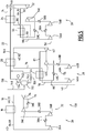
- a second installation 100 according to the invention is represented on the Figure 2 .
- This second installation 100 is intended for the implementation of a second production method according to the invention.
- the second method according to the invention differs from the first method in that the first expanded refrigeration stream 72 from the first dynamic expansion turbine 34 is separated into the first refrigerant stream 60 intended to be conveyed to the first exchanger 16 and in a first auxiliary cooling stream 102 of the second refrigeration cycle 28.
- the first auxiliary refrigeration stream 102 has a molar flow rate of between 0% and 30% of the molar flow rate of the first expanded refrigeration stream 72.
- the first auxiliary refrigeration stream 102 is introduced into the second cycle exchanger 44 of the second refrigeration cycle 28 to countercurrently cool the second high-pressure refrigerant stream 80 before it passes through the second expansion turbine 42.
- the stream 102 is mixed with the first heated refrigerant stream 66 to form the first low pressure heated stream 68.
- the first refrigerant and the second refrigerant remain totally separate, and are not mixed with each other, especially in the second cycle exchanger 44.
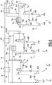
- a third installation 110 according to the invention is represented on the Figure 3 .
- This third installation 110 is intended for the implementation of a third production method according to the invention.
- the third method according to the invention differs from the first method described in FIG. 1 in that the second expanded refrigerant stream 82 is separated into the second refrigeration stream 62 intended to be introduced into the second heat exchanger 20 and into a second stream auxiliary refrigeration 112 for supplying refrigerants to the third refrigeration cycle 30.
- the molar flow rate of the second auxiliary refrigeration stream 112 is less than 25% of the molar flow rate of the second expanded refrigeration stream 82 from the second expansion turbine 42.
- This second auxiliary refrigeration stream 112 is introduced into the third cycle exchanger 54 for countercurrently cooling the third high pressure refrigeration stream 90, before its introduction into the third expansion turbine 52.
- the stream 112 after passing through the third exchanger 54, is mixed with the second heated refrigerant stream 76, before being introduced into the second cycle exchanger 44 to form at the outlet of this exchanger 44 the second low refrigerant stream pressure 78.
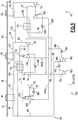
- a fourth installation 120 according to the invention is represented on the Figure 4 .
- the second expanded refrigeration stream 82 is divided into the second refrigeration stream 62 and the second auxiliary refrigeration stream 112 of the third cycle 30, as in the embodiment of FIG. Figure 3 .
- the energy consumption of this process is about 8.5 MW lower compared to the process of the Figure 1 .
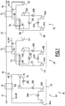
- a fifth installation 130 according to the invention is represented on the Figure 5 .
- the fifth installation 130 differs from the first installation 10 in that it comprises a separation tank 132 of a part of the pre-cooled charge stream 18, a gas expansion turbine 134, connected to a part upper balloon 132 and a static expansion valve 136, connected to a lower part of the balloon 132.
- the fifth method according to the invention differs from the first method according to the invention in that the pre-cooled charge current 18 is separated at the output of the first heat exchanger 16, into a pre-cooled charge main stream 138 and into a pre-cooled charge stream.
- auxiliary current 140 pre-cooled load.
- the pre-cooled main charge stream 138 is sent to the second heat exchanger 20 to form a high pressure LNG stream 22 and then, after passing through the third exchanger 24, a sub-cooled high pressure LNG stream 14 at a higher pressure. at 30 bars and in particular approximately equal to 62 bars.
- the pre-cooled charge auxiliary stream 140 is introduced into the separator tank 132.
- the vapor fraction 142 from the separator tank 132 is introduced into the expansion gas turbine 134 to be expanded to a pressure of at least 5 bars lower than starting pressure, and in particular substantially equal to 40 bars.
- the liquid fraction 144 is introduced into the static expansion valve 136 to be expanded to a pressure substantially identical to that of the output of the expansion turbine and in particular substantially equal to 40 bars.
- the fractions 144, 142, after their respective detents, are joined together and then introduced into the second heat exchanger 20. They form, at the outlet of the second exchanger 20, a low pressure auxiliary LNG stream 146 which is cooled in the second stage. third heat exchanger 24 to form a sub-cooled auxiliary stream 148 of LNG.
- the temperature of the auxiliary current 148 is substantially equal to that of the main current 14.
- the method thus delivers two undercooled LNG streams 14, 148 at different pressures different from at least 5 bars.
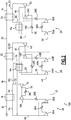
- a sixth installation 150 according to the invention is represented on the Figure 6 .
- This sixth installation is intended for the implementation of a sixth method according to the invention.
- the sixth facility 150 differs from the second facility 100 in that the third refrigeration cycle 30 is an "indirect inverted Brayton" type cycle that includes a liquid expansion turbine 152.
- the sixth method according to the invention differs from the second method according to the invention in that the third compressed refrigerant stream 90 is separated, before it passes through the third cycle exchanger 54, into a stream 154 for forming the third refrigerant stream. 66 and a gaseous stream 156 for cooling the formation stream 154.
- the forming stream 154 forms a mole fraction of less than 50% of the compressed refrigerant stream 90.
- the stream 154 is introduced into the third cycle heat exchanger 54 and then into the third heat exchanger 24 in order to liquefy substantially completely to produce a liquid stream 158 of high pressure refrigerant.
- the volume fraction of liquid in the liquid stream 158 is greater than 99%.
- This stream 158 is introduced into the liquid expansion turbine 152 at a pressure greater than 50 bars substantially equal to 73 bars and at a temperature substantially equal to the temperature of the LNG under cooling.
- the stream 158 forms, after passing through the liquid expansion turbine 152, the third refrigerant stream whose vaporized fraction does not exceed 10% by mass.
- This stream 64 is placed in heat exchange relation with the LNG stream 22 and with the stream 154 from the third cycle exchanger 54 in the third heat exchanger 24.
- the third mainly liquid refrigerant stream 64 vaporizes substantially completely in the third heat exchanger 24, so that its volume volume fraction of the liquid at the outlet of the third heat exchanger 24 is less than 1% to form the third stream of heated gaseous refrigerant 86 .
- the gaseous stream 156 is introduced into the third cycle heat exchanger 54 to form the cooled third cooled stream 91, and is then dynamically expanded in the third dynamic expansion turbine 52 to form a cooled expanded coolant gas stream 92.
- the temperature of the stream 92 is preferably below -100 ° C and is in particular equal to -118 ° C. Its pressure is preferably less than 20 bar, and is in particular equal to about 14 bar.
- the streams 66, 92 are mixed together before being introduced into the exchanger 54 to countercurrently cool the forming stream 154 to be liquefied and the refrigerating stream 156.
- This mixture 161 forms, at the outlet of the third cycle exchanger 54, the third low-pressure refrigerant stream 88.
- the formation stream 154, and consequently the third refrigerant stream 64 are obtained at least in part from the expanded gas stream 92 from the dynamic expansion in the third expansion turbine 52.
- the frigories necessary for the liquefaction of the formation stream 154 are mainly supplied by the expanded gas stream 92.
- An inverted Brayton refrigeration cycle with a gaseous refrigerant is formed between the turbine 52, the stream 92, the stream 161, the current 88, the third compression apparatus 50, the current 90, the current 156 and the current 91.
- the energy consumption of this process is 226 MW.
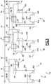
- a seventh installation according to the invention 170 is represented on the Figure 7 .
- This installation 170 is intended for the implementation of a seventh method according to the invention.
- the installation 170 differs from the third installation 110 shown on the Figure 3 in that the compressors 36C, 46C respectively connected to the first dynamic expansion turbine 34 and to the second dynamic expansion turbine 42 are each formed by two compression stages of the same power, the stages being separated by an intermediate coolant 172 cooling the gas at a temperature advantageously less than 40 ° C and for example substantially equal to 36 ° C.
- the seventh method according to the invention differs from the third method according to the invention in that the second auxiliary refrigeration stream 112, after passing through the third cycle exchanger 54, is mixed with the second heated refrigerant stream 76, after the passage of this stream 76 in the second cycle exchanger 44.
- the second auxiliary refrigeration stream 112 does not pass through the second cycle exchanger 44.
- case 7-4 when carbon dioxide is available in the plant 10, for example by being produced in the plant by decarbonation of the raw natural gas, it is advantageous to introduce at least 10% , advantageously at least 18%, in the first refrigerant fluid.
- the first refrigerant fluid comprises about 20% of carbon dioxide.
- the CO2 content must be limited to less than 50 mol% to avoid the crystallization of CO2 in the expansion turbine.
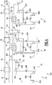
- FIG. 8 An eighth installation according to the invention 180 is represented on the Figure 8 . This eighth installation is intended for the implementation of an eighth method according to the invention.
- This installation 180 differs from the third installation 110 in that at least one first compressor 182 is common to the first compression apparatus 32 and the second compression apparatus 40 for simultaneously compressing the first refrigerant circulating in the first refrigeration cycle 26, and the second refrigerant circulating in the second refrigeration cycle 28, these fluids being mixed before they pass into the first common compressor 182.
- the installation 180 further comprises a common refrigerant 184 placed at the outlet of the common compressor 182.
- the first compression device 32 thus comprises the compressor 182 common to the two devices 32, 40 and the compressor 36C coupled to the first expansion turbine 34.
- the second compression apparatus 40 comprises, upstream of the common compressor 182, a compressor 46A, and downstream of the common compressor 182, the compressor 46C preferably coupled to the second expansion turbine 42.
- the second low pressure current 78 from the second cycle exchanger 44 is introduced into the first compressor 46A of the second compression apparatus 40.
- this stream 78 is mixed with the first low-pressure stream 68 to form an intermediate pressure mixing stream 186 greater than 20 bar and less than 30 bar.
- the intermediate pressure mixing stream 186 is then introduced into the common compressor 182 to form a medium pressure mixing stream 188 after passing through the common refrigerant 184.
- This stream 188 has a pressure greater than 35 bar and less than 50 bar.
- the stream 188 is then divided into a first intermediate stream 189A of refrigerant which is conveyed in the compressor 36C preferably coupled to the first expansion turbine 34, to form the first compressed refrigerant stream 70, and a second intermediate stream 189B of refrigerant which is introduced into the compressor 46C of the second compression apparatus 40 preferably coupled to the second expansion turbine 42, to form the second compressed refrigerant stream 82.
- This method and the corresponding installation 180 are particularly compact.
- a ninth installation 190 according to the invention is illustrated on the Figure 9 .
- the installation 190 is intended for the implementation of a ninth method according to the invention.
- the first common compressor 182 to the first compression apparatus 32 and the second compression apparatus 40 is also common to the third compression apparatus 50.
- the low pressure compressor 192 of the second compression apparatus 40 is common to the third compression apparatus 50.
- the low pressure refrigerant 194 at the outlet of the compressor 192 is also common to the second compression apparatus 40 and the third compression apparatus 50.
- the third compression apparatus 50 successively comprises the low-pressure compressor 192, common to the second compression apparatus 40 and the third compression apparatus 50, the compressor 182 common to the three compressors 32, 40, 50, and the compressor 56C preferably coupled to the third expansion turbine 52.
- the second low-pressure refrigerant stream 78 and the third low-pressure refrigerant stream 88, respectively from the second cycle heat exchanger 44 and the third cycle heat exchanger 54, are mixed with each other. other for forming a low pressure mixing stream 196.
- the low pressure mixing stream 196 is introduced into the compressor 192 common to the second apparatus 40 and the third apparatus 50 and then to the common refrigerant 194.
- the medium pressure mixing stream 188 from the common refrigerant 184 is then divided into the first intermediate stream 189A, the second intermediate stream 189B and a third intermediate stream 198 which is introduced into the compressor 56C preferably coupled to the third turbine. detent 52 to form the third compressed refrigerant stream 90.
- the arrangement described in the fifth installation 130 according to which the pre-cooled charge current 18 is separated in order to be introduced in part into a balloon 132 can be arranged in any of the installations 10, 100, 110, 120 , 150, 170, 180, 190 previously described.
- the installations according to the invention, described above, are arranged on the ground, or advantageously on a floating structure or on a structure fixed on the surface of a body of water, such as a platform or a floating recovery unit, storage and processing of hydrocarbons designated by the acronym "FPSO”.
- FPSO floating recovery unit
- the heat exchangers 16, 20, 22 in which the charging current 12, the pre-cooled charge current 18, the liquefied natural gas stream 22 and the subcooled LNG stream 14 flow in the installations 10, 100 , 110, 120, 130, 150, 170, 180 and 190, are preferably tubes and calender having sections of straight tube (conventional type) or helically wound (wound type). These exchangers are traversed by natural gas streams which may contain impurities likely to affect the proper functioning or the mechanical integrity of the exchangers.
- the tube and shell exchangers are more robust than plate heat exchangers and increase the reliability of the installation and its safety in making these exchangers.
- austenitic stainless steel for example ASTM 304, is preferred to aluminum-based alloys.
- these exchangers are tubes and calender of the standard type, made of austenitic stainless steel of the ASTM 304 type, manufactured according to standards published by the Thermal Exchanger Manufacturing Association or "TEMA".
Landscapes
- Engineering & Computer Science (AREA)
- Physics & Mathematics (AREA)
- Mechanical Engineering (AREA)
- Thermal Sciences (AREA)
- General Engineering & Computer Science (AREA)
- Ocean & Marine Engineering (AREA)
- Chemical & Material Sciences (AREA)
- Chemical Kinetics & Catalysis (AREA)
- General Chemical & Material Sciences (AREA)
- Oil, Petroleum & Natural Gas (AREA)
- Separation By Low-Temperature Treatments (AREA)
Claims (20)
- Verfahren zur Herstellung eines Stroms (14) von unterkühltem, verflüssigtem Erdgas ausgehend von einem Betriebs-Strom (12) von Erdgas, des Typs aufweisend die folgenden Schritte:- Vor-Kühlen des Betriebs-Stroms (12) von Erdgas durch Passieren durch einen ersten Wärmetauscher (16) zum Erlangen eines vor-gekühlten Betriebs-Stroms (18) mit einer Temperatur unter -20°C,- Verflüssigen des vor-gekühlten Betriebs-Stroms (18) durch Passieren durch einen zweiten Wärmetauscher (20) zum Erlangen wenigstens eines Stroms (22) von verflüssigtem Erdgas mit einer Temperatur unter -80°C,- Unter-Kühlen des Stroms von verflüssigtem Erdgas (22) durch Passieren durch einen dritten Wärmetauscher (24) zum Erlangen eines Stroms (14) von verflüssigtem, unterkühltem Erdgas mit einer Temperatur unter -120°C,- Wärmetauschen des Betriebs-Stroms (12) in dem ersten Wärmetauscher (16) mit einem ersten Strom (60) von Kältemittel,- Wärmetauschen des vor-gekühlten Betriebs-Stroms (18) in dem zweiten Wärmetauscher (20) mit einem zweiten Strom (62) von gasförmigem Kältemittel, der in einem zweiten Kühlungs-Kreis (28) zirkuliert, wobei der zweite Strom von gasförmigem Kältemittel (62) erstellt ist ausgehend von einem zweiten, gasförmigen Strom (82) von expandiertem Fluid, der von einer zweiten Turbine (42) dynamischer Expansion stammt,- Wärmetauschen des Stroms von verflüssigtem Erdgas (22) in dem dritten Wärmetauscher (24) mit einem dritten Strom (64) von Kältemittel, der in einem dritten Kühlungs-Kreis (30) zirkuliert, wobei der dritte Strom von Kältemittel (64) erstellt ist wenigstens teilweise ausgehend von einem dritten gasförmigen Strom (92) von expandiertem Fluid, der von einer dritten Turbine (52) dynamischer Expansion stammt, die von der zweiten Turbine dynamischer Expansion (42) verschieden ist,- Fördern des ersten Stroms (66) von erwärmtem Kältemittel, der am Ausgang des ersten Wärmetauschers (16) erlangt ist, zu einer ersten Verdichter-Vorrichtung (26) ohne Passieren durch den zweiten Wärmetauscher (20) und ohne Passieren durch den dritten Wärmetauscher (24),- Fördern des zweiten Stroms (76) von erwärmtem Kältemittel, der von dem zweiten Wärmetauscher (20) stammt, zu einer zweiten Verdichter-Vorrichtung (40) ohne Passieren durch den ersten Wärmetauscher (16) und ohne Passieren durch den dritten Wärmetauscher (24),- Fördern des dritten Stroms (86) von erwärmtem Kältemittel, der von dem dritten Wärmetauscher (24) stammt, zu einer dritten Verdichter-Vorrichtung (30) ohne Passieren durch den ersten Wärmetauscher (16) und ohne Passieren durch den zweiten Wärmetauscher (24),dadurch gekennzeichnet, dass der erste Strom von Kältemittel ein im Wesentlichen gasförmiger Strom ist, wobei dieser Strom in einem ersten Kühlungs-Kreis (26) erstellt ist ausgehend von einem ersten gasförmigen Strom (72) von expandiertem Kältemittelfluid, der von einer ersten Turbine (34) dynamischer Expansion stammt, wobei die zweite Turbine dynamischer Expansion von der ersten Turbine dynamischer Expansion (34) verschieden ist, wobei die dritte Turbine (52) dynamischer Expansion von der ersten Turbine dynamischer Expansion (34) verschieden ist,
und dass der erste Wärmetauscher nur zweite Fluide umfasst. - Verfahren gemäß Anspruch 1, dadurch gekennzeichnet, dass es die folgenden Schritte aufweist:- Trennen des ersten gasförmigen Stroms von expandiertem Kältemittelfluid (72) in den ersten Strom von gasförmigem Kältemittel (60) und in einen ersten Hilfs-Kühlungs-Strom (102),- Wärmetauschen des ersten Hilfs-Kühlungs-Stroms (102) in einem zweiten Kreis-Tauscher (44) mit einem zweiten Strom von verdichtetem Kältemittel (80), der von der zweiten Verdichter-Vorrichtung (40) stammt, zum Bilden eines zweiten Stroms von gekühltem, verdichtetem Kältemittel (81),- Fördern des zweiten Stroms von gekühltem, verdichtetem Kältemittel (81) zu der zweiten Expansions-Turbine (42) zum Bilden des zweiten, gasförmigen Stroms von expandiertem Kältemittelfluid (82).
- Verfahren gemäß einem der Ansprüche 1 oder 2, dadurch gekennzeichnet, dass es die folgenden Schritte aufweist:- Trennen des zweiten, gasförmigen Stroms von expandiertem Kältemittelfluid (82) in den zweiten Strom von gasförmigem Kältemittel (62) und in einen zweiten Hilfs-Kühlungs-Strom (112), und- Wärmetauschen des zweiten Hilfs-Kühlungs-Stroms (112) in einem dritten Kreis-Tauscher mit einem dritten Strom (90) von verdichtetem Kältemittel, der von der dritten Verdichter-Vorrichtung (50) stammt, zum Bilden eines dritten Stroms von gekühltem, verdichtetem Kältemittel (91),- Fördern des dritten Stroms von gekühltem, verdichtetem Kältemittel (91) zu der dritten Expansions-Turbine (52) zum Bilden des dritten, gasförmigen Stroms von expandiertem Kältemittelfluid (92).
- Verfahren gemäß irgendeinem der vorhergehenden Ansprüche, dadurch gekennzeichnet, dass die Kältemittelfluide, die respektive in dem ersten Kühlungs-Kreis (26), in dem zweiten Kühlungs-Kreis (28) und in dem dritten Kühlungs-Kreis (30) zirkulieren, völlig getrennt sind,
wobei der erste Strom von erwärmtem Kältemittel (66), der von dem ersten Wärmetauscher (16) stammt, der zweite Strom von erwärmtem Kältemittel (76), der von dem zweiten Wärmetauscher (20) stammt, und der dritte Strom von erwärmtem Kältemittel (86), der von dem dritten Wärmetauscher (24) stammt, respektive gefördert werden zu den verschiedenen Verdichtern respektive der ersten Verdichter-Vorrichtung (32), der zweiten Verdichter-Vorrichtung (40) und der dritten Verdichter-Vorrichtung (50), um getrennt voneinander verdichtet zu werden. - Verfahren gemäß irgendeinem der Ansprüche 1 bis 3, dadurch gekennzeichnet, dass es die folgenden Schritte aufweist:- Bilden wenigstens eines Misch-Stroms (186; 196) ausgehend von wenigstens zweien unter dem ersten Strom von erwärmtem Kältemittel (66), dem zweiten Strom von erwärmtem Kältemittel (76) und dem dritten Strom von erwärmtem Kältemittel (86),- Verdichten des oder jedes Misch-Stroms (186; 196) in einem gemeinsamen Verdichter (182; 192) aus wenigstens zweien von der ersten Verdichter-Vorrichtung (32), der zweiten Verdichter-Vorrichtung (40) und der dritten Verdichter-Vorrichtung (50) .
- Verfahren gemäß irgendeinem der vorhergehenden Ansprüche, dadurch gekennzeichnet, dass der dritte Strom von Kältemittel (64) im Wesentlichen gasförmig ist vor seiner Einbringung in den dritten Wärmetauscher (24).
- Verfahren gemäß irgendeinem der Ansprüche 1 bis 5, dadurch gekennzeichnet, dass es die folgenden Schritte aufweist:- Trennen des Stroms von verdichtetem Kältemittel (90), der von der dritten Verdichter-Vorrichtung (50) stammt, in einen Strom (154) zur Bildung des dritten Stroms von Kältemittel (64) und in einen gasförmigen Strom (156) zur Kühlung des Stroms zur Bildung (154),- Fördern des gasförmigen Stroms zur Kühlung (156) zu der dritten Expansions-Turbine (52), und Wärmetauschen des gasförmigen, expandierten Stroms zur Kühlung (92), der von der dritten Expansions-Turbine (52) stammt, mit dem Strom zur Bildung (154) zum Verflüssigen des Stroms zur Bildung (154),- Fördern des verflüssigten Stroms zur Bildung (154) zu einer hydraulischen Expansions-Turbine (152) zum Bilden des dritten Stroms von Kältemittel (64) in im Wesentlichen flüssiger Form,- Wärmetauschen des dritten Stroms von Kältemittel (64) in im Wesentlichen flüssiger Form mit dem Strom von verflüssigtem Erdgas (22) in dem dritten Wärmetauscher (24).
- Verfahren gemäß irgendeinem der vorhergehenden Ansprüche, dadurch gekennzeichnet, dass es die folgenden Schritte aufweist:- Teilen des vor-gekühlten Betriebs-Stroms (18), der von dem ersten Wärmetauscher (16) stammt, in einen vor-gekühlten Haupt-Betriebs-Strom (138) und in einen Expansions-Hilfs-Strom (140),- Expandieren des Expansions-Hilfs-Stroms (140) bis auf einen niedrigen Druck, der um wenigstens 5 bar kleiner ist als der Druck des Haupt-Stroms (138), und- sukzessive Passieren eines Stroms, der von dem Expansions-Strom (140) stammt, durch den zweiten Wärmetauscher (20) und durch den dritten Wärmetauscher (24) zum Liefern eines Stroms (148) von verflüssigtem, unterkühltem Erdgas niedrigen Drucks.
- Verfahren gemäß irgendeinem der vorhergehenden Ansprüche, dadurch gekennzeichnet, dass der Molgehalt an Stickstoff jedes von dem ersten Strom von Kältemittel (60), des zweiten Stroms von Kältemittel (62) und des dritten Stroms von Kältemittel (64) größer als 90% ist.
- Verfahren gemäß irgendeinem der Ansprüche 1 bis 8, dadurch gekennzeichnet, dass der erste Strom von Kältemittel (60) auf Basis von Erdgas gebildet ist, das einen Molgehalt an Methan von größer als 70% hat.
- Verfahren gemäß Anspruch 10, dadurch gekennzeichnet, dass der zweite Strom von Kältemittel (62) einen Molgehalt an Methan von größer als 90% hat.
- Verfahren gemäß irgendeinem der Ansprüche 10 oder 11, dadurch gekennzeichnet, dass der erste Strom von Kältemittel (60) einen Molgehalt an Kohlenstoffdioxid von größer als 5% hat.
- Verfahren gemäß irgendeinem der vorhergehenden Ansprüche, dadurch gekennzeichnet, dass der Druck am Ausgang der ersten Verdichter-Vorrichtung (32) größer ist als 50 bar, vorteilhafterweise größer ist als 70 bar, und dass der Druck am Eingang der ersten Verdichter-Vorrichtung (32) größer ist als 10 bar, vorteilhafterweise größer ist als 15 bar.
- Verfahren gemäß irgendeinem der vorhergehenden Ansprüche, dadurch gekennzeichnet, dass jeder von dem zweiten Wärmetauscher und von dem dritten Wärmetauscher nur zwei Fluide umfasst.
- Verfahren gemäß irgendeinem der vorhergehenden Ansprüche, dadurch gekennzeichnet, dass ein zweiter Strom von verdichtetem Kältemittel am Ausgang der zweiten Verdichter-Vorrichtung gebildet ist, wobei der zweite Strom von verdichtetem Kältemittel nach der Kühlung in die zweite Expansions-Turbine eingebracht wird ohne Passieren durch den ersten Wärmetauscher und durch den dritten Wärmetauscher.
- Einrichtung (10; 100; 110; 120; 130; 150; 170; 180; 190) zur Herstellung eines Stroms (14) von verflüssigtem, unterkühltem Erdgas ausgehend von einem Betriebs-Strom (12) von Erdgas, des Typs aufweisend:- Mittel zum Vor-Kühlen des Betriebs-Stroms (12) von Erdgas, mit einem ersten Wärmetauscher (16) zum Erlangen eines vor-gekühlten Betriebs-Stroms (18) mit einer Temperatur unter -20°C,- Mittel zum Verflüssigen des vor-gekühlten Betriebs-Stroms, mit einem zweiten Wärmetauscher (20) zum Erlangen wenigstens eines Stroms (22) von verflüssigtem Erdgas mit einer Temperatur unter -80°C,- Mittel zum Unter-Kühlen des Stroms von verflüssigtem Erdgas, mit einem dritten Wärmetauscher (24) zum Erlangen eines Stroms (14) von verflüssigtem, unterkühltem Erdgas mit einer Temperatur unter -120°C,- einen ersten Kühlungs-Kreis (26), wobei der Betriebs-Stroms (12) in dem ersten Wärmetauscher (16) mit einem ersten Strom (60) von Kältemittel wärmegetauscht wird,- einen zweiten Kühlungs-Kreis (28), mit einer zweiten Turbine dynamischer Expansion (42) und einer zweiten Verdichter-Vorrichtung (42), wobei der vor-gekühlte Betriebs-Strom (18) in dem zweiten Wärmetauscher (20) mit einem zweiten Strom (62) von gasförmigem Kältemittel wärmegetauscht wird, das erstellt wird ausgehend von einem zweiten, gasförmigen Strom (76) von expandiertem Kältemittelfluid, der von der zweiten Turbine dynamischer Expansion (42) stammt,- einen dritten Kühlungs-Kreis (30) mit einer dritten Turbine dynamischer Expansion (52), die von der zweiten Turbine dynamischer Expansion (42) verschieden ist, und einer dritten Verdichter-Vorrichtung (50), wobei der Strom von verflüssigtem Erdgas (22) in dem dritten Wärmetauscher (24) wärmegetauscht wird mit einem dritten Strom (64) von Kältemittel, der in dem drittem Kühlungs-Kreis (30) zirkuliert, wobei der dritte Strom von Kältemittel (64) erstellt ist zumindest teilweise ausgehend von einem dritten, gasförmigen Strom (92) von expandiertem Fluid, der von der dritten Turbine dynamischer Expansion (52) stammt,wobei der erste Kühlungs-Kreis (26) aufweist Mittel (66, 68) zum Fördern des ersten Stroms von erwärmtem Kältemittel (66), der erlangt wird am Ausgang des ersten Wärmetauschers (16), zu der ersten Verdichter-Vorrichtung (32) ohne durch den zweiten Wärmetauscher (20) zu passieren und ohne durch den dritten Wärmetauscher (24) zu passieren,
wobei der zweite Kühlungs-Kreis (28) aufweist Mittel (76, 78) zum Fördern des zweiten Stroms von erwärmtem Kältemittel (76), der erlangt wird am Ausgang des zweiten Wärmetauschers (20), zu der zweiten Verdichter-Vorrichtung (40) ohne durch den ersten Wärmetauscher (16) zu passieren und ohne durch den dritten Wärmetauscher (24) zu passieren,
wobei der dritte Kühlungs-Kreis (30) aufweist Mittel (86, 88) zum Fördern des dritten Stroms erwärmten Kältemittels (86), der von dem dritten Wärmetauscher stammt (24), zu der dritten Verdichter-Vorrichtung (50) ohne durch den ersten Wärmetauscher (16) zu passieren und ohne durch den zweiten Wärmetauscher (20) zu passieren,
dadurch gekennzeichnet, dass
der erste Kühlungskreis aufweist eine erste Turbine dynamischer Expansion (34) und eine erste Verdichter-Vorrichtung (32), wobei der Betriebs-Strom (12) in dem ersten Wärmetauscher (16) wärmegetauscht wird mit einem ersten Strom (60) von im Wesentlichen gasförmigem Kältemittel, das in dem ersten Kühlungs-Kreis (26) erstellt wird ausgehend von einem ersten gasförmigen Strom (72) von expandiertem Kältemittelfluid, der von der ersten Turbine dynamischer Expansion (34) stammt, und dass die zweite Turbine dynamischer Expansion (42) von der ersten Turbine dynamischer Expansion (34) verschieden ist, wobei die dritte Turbine dynamischer Expansion (52) verschieden ist von der ersten Turbine dynamischer Expansion (34),
und dass der erste Wärmetauscher nur zwei Fluide umfasst. - Einrichtung (10, 100, 110, 120, 130; 150; 170; 180; 190) gemäß Anspruch 16, dadurch gekennzeichnet, dass der erste Wärmetauscher (16), der zweite Wärmetauscher (20) und der dritte Wärmetauscher (24) aus Rohren und Kühlergrill klassischen Typs oder gewickelt sind.
- Einrichtung (10, 100, 110, 120, 130; 150; 170; 180; 190) gemäß Anspruch 17, dadurch gekennzeichnet, dass der erste Wärmetauscher (16), der zweite Wärmetauscher (20) und der dritte Wärmetauscher (24) aus rostfreiem austenitischem Stahl sind.
- Einrichtung (10; 100; 110; 120; 170; 180; 190) gemäß einem der Ansprüche 17 oder 18, dadurch gekennzeichnet, dass der erste Wärmetauscher (16), der zweite Wärmetauscher (20) und der dritte Wärmetauscher (24) aus Rohren und Kühlergrill klassischen Typs sind.
- Einrichtung (10; 100; 110; 120; 170; 180; 190) gemäß irgendeinem der Ansprüche 16 bis 19, dadurch gekennzeichnet, dass der zweite Wärmetauscher und der dritte Wärmetauscher nur zwei Fluide umfassen.
Applications Claiming Priority (2)
| Application Number | Priority Date | Filing Date | Title |
|---|---|---|---|
| FR0857996A FR2938903B1 (fr) | 2008-11-25 | 2008-11-25 | Procede de production d'un courant de gaz naturel liquefie sous-refroidi a partir d'un courant de charge de gaz naturel et installation associee |
| PCT/FR2009/052239 WO2010061102A2 (fr) | 2008-11-25 | 2009-11-20 | Procédé de production d'un courant de gaz naturel liquéfié sous-refroidi à partir d'un courant de charge de gaz naturel et installation associée. |
Publications (2)
| Publication Number | Publication Date |
|---|---|
| EP2368083A2 EP2368083A2 (de) | 2011-09-28 |
| EP2368083B1 true EP2368083B1 (de) | 2019-07-24 |
Family
ID=40902590
Family Applications (1)
| Application Number | Title | Priority Date | Filing Date |
|---|---|---|---|
| EP09795481.2A Active EP2368083B1 (de) | 2008-11-25 | 2009-11-20 | Verfahren zur erzeugung eines stroms aus unterkühltem verflüssigtem erdgas unter verwendung eines erdgaszufuhrstroms und zugehörige einrichtung |
Country Status (13)
| Country | Link |
|---|---|
| US (1) | US9506690B2 (de) |
| EP (1) | EP2368083B1 (de) |
| JP (1) | JP5642697B2 (de) |
| KR (1) | KR101677306B1 (de) |
| CN (1) | CN102405390B (de) |
| AU (1) | AU2009321449B2 (de) |
| BR (1) | BRPI0921562B1 (de) |
| CA (1) | CA2744450C (de) |
| ES (1) | ES2749230T3 (de) |
| FR (1) | FR2938903B1 (de) |
| MX (1) | MX2011005475A (de) |
| PT (1) | PT2368083T (de) |
| WO (1) | WO2010061102A2 (de) |
Families Citing this family (31)
| Publication number | Priority date | Publication date | Assignee | Title |
|---|---|---|---|---|
| KR101259238B1 (ko) * | 2007-12-07 | 2013-04-29 | 드렛서-랜드 캄파니 | 가스 액화 시스템을 위한 압축기 시스템 및 그 방법 |
| JP5660845B2 (ja) * | 2010-10-13 | 2015-01-28 | 三菱重工業株式会社 | 液化方法、液化装置およびこれを備える浮体式液化ガス製造設備 |
| CA2827247A1 (en) * | 2011-02-16 | 2012-08-23 | Conocophillips Company | Integrated waste heat recovery in liquefied natural gas facility |
| CN102425899B (zh) * | 2011-11-03 | 2014-01-01 | 苏州市兴鲁空分设备科技发展有限公司 | 低温装置中低温冷冻机的使用方法 |
| CN102504901A (zh) * | 2011-11-03 | 2012-06-20 | 苏州市兴鲁空分设备科技发展有限公司 | 天然气液化方法 |
| CN102538390B (zh) * | 2011-12-22 | 2014-08-06 | 西安交通大学 | 一种天然气液化系统及其方法 |
| US9863696B2 (en) * | 2012-06-06 | 2018-01-09 | Keppel Offshore & Marine Technology Centre Pte Ltd | System and process for natural gas liquefaction |
| FR2993643B1 (fr) * | 2012-07-17 | 2014-08-22 | Saipem Sa | Procede de liquefaction de gaz naturel avec changement de phase |
| CN104266454A (zh) * | 2014-09-05 | 2015-01-07 | 西安交通大学 | 燃气-超临界二氧化碳联合动力的液化天然气生产系统 |
| CN104405599B (zh) * | 2014-09-24 | 2017-02-01 | 西安交通大学 | 一种利用太阳能的燃气‑超临界二氧化碳联合动力发电系统 |
| JP6415989B2 (ja) * | 2015-01-05 | 2018-10-31 | 三菱重工サーマルシステムズ株式会社 | 液化ガス用冷却装置 |
| CN204705105U (zh) * | 2015-04-16 | 2015-10-14 | 中国海洋石油总公司 | 一种橇装的天然气液化装置 |
| US20170167786A1 (en) * | 2015-12-14 | 2017-06-15 | Fritz Pierre, JR. | Pre-Cooling of Natural Gas by High Pressure Compression and Expansion |
| US20230266059A1 (en) * | 2017-05-12 | 2023-08-24 | Samsung Heavy Ind. Co., Ltd | Natural gas liquefaction apparatus |
| EP3688391A1 (de) * | 2017-09-29 | 2020-08-05 | ExxonMobil Upstream Research Company | Erdgasverflüssigung durch ein hochdruckexpansionsverfahren |
| JP2019095079A (ja) * | 2017-11-17 | 2019-06-20 | 大陽日酸株式会社 | 高温超電導電力機器用冷却システム及びその運転方法 |
| CN108167086B (zh) * | 2017-11-21 | 2022-06-07 | 上海齐耀动力技术有限公司 | 一种高压富氧燃烧斯特林发电系统及其控制方法 |
| JP6556891B2 (ja) * | 2018-03-09 | 2019-08-07 | 三菱重工サーマルシステムズ株式会社 | 液化ガス用冷却装置およびそのメンテナンス方法 |
| WO2019236246A1 (en) | 2018-06-07 | 2019-12-12 | Exxonmobil Upstream Research Company | Pretreatment and pre-cooling of natural gas by high pressure compression and expansion |
| JP7179155B2 (ja) | 2018-08-22 | 2022-11-28 | エクソンモービル アップストリーム リサーチ カンパニー | 高圧エキスパンダプロセスのための一次ループ始動方法 |
| US11555651B2 (en) | 2018-08-22 | 2023-01-17 | Exxonmobil Upstream Research Company | Managing make-up gas composition variation for a high pressure expander process |
| SG11202101058QA (en) | 2018-08-22 | 2021-03-30 | Exxonmobil Upstream Res Co | Heat exchanger configuration for a high pressure expander process and a method of natural gas liquefaction using the same |
| WO2020245510A1 (fr) | 2019-06-04 | 2020-12-10 | Total Se | Installation pour produire du gnl à partir de gaz naturel, support flottant intégrant une telle installation, et procédé correspondant |
| FR3113116B1 (fr) * | 2020-07-30 | 2022-10-14 | Air Liquide | Installation et procédé de réfrigération d’un fluide |
| US12123646B2 (en) | 2021-04-16 | 2024-10-22 | Praxair Technology, Inc. | System and method to produce liquefied natural gas using a three pinion integral gear machine |
| US20230114229A1 (en) * | 2021-10-13 | 2023-04-13 | Henry Edward Howard | System and method to produce liquefied natural gas |
| US20230113326A1 (en) * | 2021-10-13 | 2023-04-13 | Henry Edward Howard | System and method to produce liquefied natural gas |
| US20230115492A1 (en) * | 2021-10-13 | 2023-04-13 | Henry Edward Howard | System and method to produce liquefied natural gas |
| US20230129424A1 (en) * | 2021-10-21 | 2023-04-27 | Henry Edward Howard | System and method to produce liquefied natural gas |
| US12025370B2 (en) * | 2022-10-14 | 2024-07-02 | Air Products And Chemicals, Inc. | Reverse Brayton LNG production process |
| WO2024172687A1 (ru) * | 2023-02-17 | 2024-08-22 | Публичное акционерное общество "НОВАТЭК" | Способ сжижения природного газа |
Family Cites Families (18)
| Publication number | Priority date | Publication date | Assignee | Title |
|---|---|---|---|---|
| US3581510A (en) * | 1968-07-08 | 1971-06-01 | Phillips Petroleum Co | Gas liquefaction by refrigeration with parallel expansion of the refrigerant |
| US3964891A (en) * | 1972-09-01 | 1976-06-22 | Heinrich Krieger | Process and arrangement for cooling fluids |
| IT1176290B (it) * | 1984-06-12 | 1987-08-18 | Snam Progetti | Processo per raffreddamento e liquefazione di gas a basso punto di ebollizione |
| SE465373B (sv) * | 1990-01-15 | 1991-09-02 | Avesta Ab | Austenitiskt rostfritt staal |
| AUPM485694A0 (en) | 1994-04-05 | 1994-04-28 | Bhp Petroleum Pty. Ltd. | Liquefaction process |
| US5931021A (en) * | 1997-06-24 | 1999-08-03 | Shnaid; Isaac | Straightforward method and once-through apparatus for gas liquefaction |
| US6308531B1 (en) * | 1999-10-12 | 2001-10-30 | Air Products And Chemicals, Inc. | Hybrid cycle for the production of liquefied natural gas |
| GB0006265D0 (en) * | 2000-03-15 | 2000-05-03 | Statoil | Natural gas liquefaction process |
| US6412302B1 (en) * | 2001-03-06 | 2002-07-02 | Abb Lummus Global, Inc. - Randall Division | LNG production using dual independent expander refrigeration cycles |
| FR2823995B1 (fr) * | 2001-04-25 | 2008-06-06 | Alfa Laval Vicarb | Dispositif perfectionne d'echange et/ou de reaction entre fluides |
| US6494054B1 (en) * | 2001-08-16 | 2002-12-17 | Praxair Technology, Inc. | Multicomponent refrigeration fluid refrigeration system with auxiliary ammonia cascade circuit |
| US6601407B1 (en) * | 2002-11-22 | 2003-08-05 | Praxair Technology, Inc. | Cryogenic air separation with two phase feed air turboexpansion |
| US6742357B1 (en) | 2003-03-18 | 2004-06-01 | Air Products And Chemicals, Inc. | Integrated multiple-loop refrigeration process for gas liquefaction |
| DE10355935A1 (de) * | 2003-11-29 | 2005-06-30 | Linde Ag | Verfahren zum Verflüssigen eines Kohlenwasserstoff-reichen Stromes |
| FR2884303B1 (fr) * | 2005-04-11 | 2009-12-04 | Technip France | Procede de sous-refroidissement d'un courant de gnl par refroidissement au moyen d'un premier cycle de refrigeration et installation associee. |
| US20070157663A1 (en) * | 2005-07-07 | 2007-07-12 | Fluor Technologies Corporation | Configurations and methods of integrated NGL recovery and LNG liquefaction |
| WO2007021351A1 (en) * | 2005-08-09 | 2007-02-22 | Exxonmobil Upstream Research Company | Natural gas liquefaction process for lng |
| US20080141711A1 (en) * | 2006-12-18 | 2008-06-19 | Mark Julian Roberts | Hybrid cycle liquefaction of natural gas with propane pre-cooling |
-
2008
- 2008-11-25 FR FR0857996A patent/FR2938903B1/fr not_active Expired - Fee Related
-
2009
- 2009-11-20 ES ES09795481T patent/ES2749230T3/es active Active
- 2009-11-20 PT PT97954812T patent/PT2368083T/pt unknown
- 2009-11-20 CN CN2009801539755A patent/CN102405390B/zh active Active
- 2009-11-20 AU AU2009321449A patent/AU2009321449B2/en active Active
- 2009-11-20 BR BRPI0921562A patent/BRPI0921562B1/pt active IP Right Grant
- 2009-11-20 JP JP2011538024A patent/JP5642697B2/ja active Active
- 2009-11-20 CA CA2744450A patent/CA2744450C/fr active Active
- 2009-11-20 EP EP09795481.2A patent/EP2368083B1/de active Active
- 2009-11-20 KR KR1020117011876A patent/KR101677306B1/ko active Active
- 2009-11-20 WO PCT/FR2009/052239 patent/WO2010061102A2/fr not_active Ceased
- 2009-11-20 MX MX2011005475A patent/MX2011005475A/es active IP Right Grant
- 2009-11-24 US US12/624,587 patent/US9506690B2/en active Active
Non-Patent Citations (1)
| Title |
|---|
| None * |
Also Published As
| Publication number | Publication date |
|---|---|
| US9506690B2 (en) | 2016-11-29 |
| JP5642697B2 (ja) | 2014-12-17 |
| CA2744450A1 (fr) | 2010-06-03 |
| FR2938903A1 (fr) | 2010-05-28 |
| BRPI0921562A2 (pt) | 2019-05-07 |
| CN102405390A (zh) | 2012-04-04 |
| US20100126214A1 (en) | 2010-05-27 |
| CN102405390B (zh) | 2013-11-06 |
| KR20110094012A (ko) | 2011-08-19 |
| AU2009321449B2 (en) | 2016-01-07 |
| MX2011005475A (es) | 2011-06-16 |
| ES2749230T3 (es) | 2020-03-19 |
| KR101677306B1 (ko) | 2016-11-29 |
| EP2368083A2 (de) | 2011-09-28 |
| WO2010061102A2 (fr) | 2010-06-03 |
| JP2012513005A (ja) | 2012-06-07 |
| FR2938903B1 (fr) | 2013-02-08 |
| BRPI0921562B1 (pt) | 2020-06-09 |
| AU2009321449A1 (en) | 2010-06-03 |
| CA2744450C (fr) | 2017-01-24 |
| WO2010061102A3 (fr) | 2012-03-22 |
| PT2368083T (pt) | 2019-10-29 |
Similar Documents
| Publication | Publication Date | Title |
|---|---|---|
| EP2368083B1 (de) | Verfahren zur erzeugung eines stroms aus unterkühltem verflüssigtem erdgas unter verwendung eines erdgaszufuhrstroms und zugehörige einrichtung | |
| JP6772268B2 (ja) | 液体窒素によって強化された膨張器ベースのlng生産工程 | |
| US8650906B2 (en) | System and method for recovering and liquefying boil-off gas | |
| FR3053771B1 (fr) | Procede de liquefaction de gaz naturel et de recuperation d'eventuels liquides du gaz naturel comprenant deux cycles refrigerant semi-ouverts au gaz naturel et un cycle refrigerant ferme au gaz refrigerant | |
| EP2344821B1 (de) | Verfahren zur erzeugung von flüssigen und gasförmigen stickstoffströmen, heliumreicher, gasförmiger strom und stickstoffabgereicherter kohlenwasserstoffstrom und zugehörige anlage | |
| EP2724100B1 (de) | Verfahren zur verflüssigung von erdgas mit einem geschlossenen dreifach-kühlgaskreislauf | |
| EP2724099B1 (de) | Verfahren zur verflüssigung von erdgas mit einer kühlgasmischung | |
| US20180231303A1 (en) | Pre-Cooling of Natural Gas by High Pressure Compression and Expansion | |
| US20140083132A1 (en) | Process for liquefaction of natural gas | |
| FR2675888A1 (fr) | Procede a l'utilisation du gaz naturel liquefie (gnl) associe a un expanseur a froid pour produire de l'azote liquide. | |
| FR2778232A1 (fr) | Procede et dispositif de liquefaction d'un gaz naturel sans separation de phases sur les melanges refrigerants | |
| JP6429867B2 (ja) | フローティングタンク用途における残存lngの気化及び回収のための統合カスケードプロセス | |
| EP4348138A1 (de) | Verfahren und anlage zur wasserstoffverflüssigung | |
| EP3322948B1 (de) | Verfahren zur expansion und lagerung eines stroms aus verflüssigtem erdgas aus einer erdgasverflüssigungsanlage und zugehörige anlage | |
| CN110268214A (zh) | 用于液化天然气的设备和方法及包括该设备的船 | |
| WO2005103583A1 (fr) | Procede de liquefaction d’un gaz integrant un appareillage de refroidissement thermo-acoustique | |
| FR3033397A1 (fr) | Procede de compression et de refroidissement d’un melange gazeux | |
| EP4496969A1 (de) | Verfahren zur verflüssigung eines methanreichen einsatzgases und entsprechende anlage | |
| EP4264152A1 (de) | Vorrichtung und verfahren zur vorkühlung eines gasstroms | |
| CN110537064A (zh) | 用于液化天然气的设备和方法及包括该设备的船 | |
| OA16795A (fr) | Procédé de liquéfaction de gaz naturel avec un mélange de gaz réfrigérant. |
Legal Events
| Date | Code | Title | Description |
|---|---|---|---|
| PUAI | Public reference made under article 153(3) epc to a published international application that has entered the european phase |
Free format text: ORIGINAL CODE: 0009012 |
|
| 17P | Request for examination filed |
Effective date: 20110624 |
|
| AK | Designated contracting states |
Kind code of ref document: A2 Designated state(s): AT BE BG CH CY CZ DE DK EE ES FI FR GB GR HR HU IE IS IT LI LT LU LV MC MK MT NL NO PL PT RO SE SI SK SM TR |
|
| RIN1 | Information on inventor provided before grant (corrected) |
Inventor name: VOVARD, SYLVAIN Inventor name: PARADOWSKI, HENRI |
|
| DAX | Request for extension of the european patent (deleted) | ||
| R17D | Deferred search report published (corrected) |
Effective date: 20120322 |
|
| STAA | Information on the status of an ep patent application or granted ep patent |
Free format text: STATUS: EXAMINATION IS IN PROGRESS |
|
| 17Q | First examination report despatched |
Effective date: 20180305 |
|
| GRAP | Despatch of communication of intention to grant a patent |
Free format text: ORIGINAL CODE: EPIDOSNIGR1 |
|
| STAA | Information on the status of an ep patent application or granted ep patent |
Free format text: STATUS: GRANT OF PATENT IS INTENDED |
|
| INTG | Intention to grant announced |
Effective date: 20190125 |
|
| GRAS | Grant fee paid |
Free format text: ORIGINAL CODE: EPIDOSNIGR3 |
|
| GRAJ | Information related to disapproval of communication of intention to grant by the applicant or resumption of examination proceedings by the epo deleted |
Free format text: ORIGINAL CODE: EPIDOSDIGR1 |
|
| GRAL | Information related to payment of fee for publishing/printing deleted |
Free format text: ORIGINAL CODE: EPIDOSDIGR3 |
|
| STAA | Information on the status of an ep patent application or granted ep patent |
Free format text: STATUS: EXAMINATION IS IN PROGRESS |
|
| GRAR | Information related to intention to grant a patent recorded |
Free format text: ORIGINAL CODE: EPIDOSNIGR71 |
|
| STAA | Information on the status of an ep patent application or granted ep patent |
Free format text: STATUS: GRANT OF PATENT IS INTENDED |
|
| GRAA | (expected) grant |
Free format text: ORIGINAL CODE: 0009210 |
|
| STAA | Information on the status of an ep patent application or granted ep patent |
Free format text: STATUS: THE PATENT HAS BEEN GRANTED |
|
| INTC | Intention to grant announced (deleted) | ||
| INTG | Intention to grant announced |
Effective date: 20190613 |
|
| AK | Designated contracting states |
Kind code of ref document: B1 Designated state(s): AT BE BG CH CY CZ DE DK EE ES FI FR GB GR HR HU IE IS IT LI LT LU LV MC MK MT NL NO PL PT RO SE SI SK SM TR |
|
| REG | Reference to a national code |
Ref country code: GB Ref legal event code: FG4D Free format text: NOT ENGLISH |
|
| REG | Reference to a national code |
Ref country code: CH Ref legal event code: EP |
|
| REG | Reference to a national code |
Ref country code: DE Ref legal event code: R096 Ref document number: 602009059241 Country of ref document: DE |
|
| REG | Reference to a national code |
Ref country code: AT Ref legal event code: REF Ref document number: 1158687 Country of ref document: AT Kind code of ref document: T Effective date: 20190815 |
|
| REG | Reference to a national code |
Ref country code: IE Ref legal event code: FG4D Free format text: LANGUAGE OF EP DOCUMENT: FRENCH |
|
| REG | Reference to a national code |
Ref country code: PT Ref legal event code: SC4A Ref document number: 2368083 Country of ref document: PT Date of ref document: 20191029 Kind code of ref document: T Free format text: AVAILABILITY OF NATIONAL TRANSLATION Effective date: 20191016 |
|
| REG | Reference to a national code |
Ref country code: NL Ref legal event code: MP Effective date: 20190724 |
|
| REG | Reference to a national code |
Ref country code: LT Ref legal event code: MG4D |
|
| REG | Reference to a national code |
Ref country code: AT Ref legal event code: MK05 Ref document number: 1158687 Country of ref document: AT Kind code of ref document: T Effective date: 20190724 |
|
| PG25 | Lapsed in a contracting state [announced via postgrant information from national office to epo] |
Ref country code: LT Free format text: LAPSE BECAUSE OF FAILURE TO SUBMIT A TRANSLATION OF THE DESCRIPTION OR TO PAY THE FEE WITHIN THE PRESCRIBED TIME-LIMIT Effective date: 20190724 Ref country code: SE Free format text: LAPSE BECAUSE OF FAILURE TO SUBMIT A TRANSLATION OF THE DESCRIPTION OR TO PAY THE FEE WITHIN THE PRESCRIBED TIME-LIMIT Effective date: 20190724 Ref country code: NL Free format text: LAPSE BECAUSE OF FAILURE TO SUBMIT A TRANSLATION OF THE DESCRIPTION OR TO PAY THE FEE WITHIN THE PRESCRIBED TIME-LIMIT Effective date: 20190724 Ref country code: BG Free format text: LAPSE BECAUSE OF FAILURE TO SUBMIT A TRANSLATION OF THE DESCRIPTION OR TO PAY THE FEE WITHIN THE PRESCRIBED TIME-LIMIT Effective date: 20191024 Ref country code: NO Free format text: LAPSE BECAUSE OF FAILURE TO SUBMIT A TRANSLATION OF THE DESCRIPTION OR TO PAY THE FEE WITHIN THE PRESCRIBED TIME-LIMIT Effective date: 20191024 Ref country code: HR Free format text: LAPSE BECAUSE OF FAILURE TO SUBMIT A TRANSLATION OF THE DESCRIPTION OR TO PAY THE FEE WITHIN THE PRESCRIBED TIME-LIMIT Effective date: 20190724 Ref country code: AT Free format text: LAPSE BECAUSE OF FAILURE TO SUBMIT A TRANSLATION OF THE DESCRIPTION OR TO PAY THE FEE WITHIN THE PRESCRIBED TIME-LIMIT Effective date: 20190724 Ref country code: FI Free format text: LAPSE BECAUSE OF FAILURE TO SUBMIT A TRANSLATION OF THE DESCRIPTION OR TO PAY THE FEE WITHIN THE PRESCRIBED TIME-LIMIT Effective date: 20190724 |
|
| PG25 | Lapsed in a contracting state [announced via postgrant information from national office to epo] |
Ref country code: IS Free format text: LAPSE BECAUSE OF FAILURE TO SUBMIT A TRANSLATION OF THE DESCRIPTION OR TO PAY THE FEE WITHIN THE PRESCRIBED TIME-LIMIT Effective date: 20191124 Ref country code: LV Free format text: LAPSE BECAUSE OF FAILURE TO SUBMIT A TRANSLATION OF THE DESCRIPTION OR TO PAY THE FEE WITHIN THE PRESCRIBED TIME-LIMIT Effective date: 20190724 Ref country code: GR Free format text: LAPSE BECAUSE OF FAILURE TO SUBMIT A TRANSLATION OF THE DESCRIPTION OR TO PAY THE FEE WITHIN THE PRESCRIBED TIME-LIMIT Effective date: 20191025 |
|
| REG | Reference to a national code |
Ref country code: ES Ref legal event code: FG2A Ref document number: 2749230 Country of ref document: ES Kind code of ref document: T3 Effective date: 20200319 |
|
| PG25 | Lapsed in a contracting state [announced via postgrant information from national office to epo] |
Ref country code: RO Free format text: LAPSE BECAUSE OF FAILURE TO SUBMIT A TRANSLATION OF THE DESCRIPTION OR TO PAY THE FEE WITHIN THE PRESCRIBED TIME-LIMIT Effective date: 20190724 Ref country code: DK Free format text: LAPSE BECAUSE OF FAILURE TO SUBMIT A TRANSLATION OF THE DESCRIPTION OR TO PAY THE FEE WITHIN THE PRESCRIBED TIME-LIMIT Effective date: 20190724 Ref country code: EE Free format text: LAPSE BECAUSE OF FAILURE TO SUBMIT A TRANSLATION OF THE DESCRIPTION OR TO PAY THE FEE WITHIN THE PRESCRIBED TIME-LIMIT Effective date: 20190724 Ref country code: PL Free format text: LAPSE BECAUSE OF FAILURE TO SUBMIT A TRANSLATION OF THE DESCRIPTION OR TO PAY THE FEE WITHIN THE PRESCRIBED TIME-LIMIT Effective date: 20190724 |
|
| PG25 | Lapsed in a contracting state [announced via postgrant information from national office to epo] |
Ref country code: CZ Free format text: LAPSE BECAUSE OF FAILURE TO SUBMIT A TRANSLATION OF THE DESCRIPTION OR TO PAY THE FEE WITHIN THE PRESCRIBED TIME-LIMIT Effective date: 20190724 Ref country code: SK Free format text: LAPSE BECAUSE OF FAILURE TO SUBMIT A TRANSLATION OF THE DESCRIPTION OR TO PAY THE FEE WITHIN THE PRESCRIBED TIME-LIMIT Effective date: 20190724 Ref country code: IS Free format text: LAPSE BECAUSE OF FAILURE TO SUBMIT A TRANSLATION OF THE DESCRIPTION OR TO PAY THE FEE WITHIN THE PRESCRIBED TIME-LIMIT Effective date: 20200224 Ref country code: SM Free format text: LAPSE BECAUSE OF FAILURE TO SUBMIT A TRANSLATION OF THE DESCRIPTION OR TO PAY THE FEE WITHIN THE PRESCRIBED TIME-LIMIT Effective date: 20190724 |
|
| REG | Reference to a national code |
Ref country code: DE Ref legal event code: R097 Ref document number: 602009059241 Country of ref document: DE Ref country code: DE Ref legal event code: R119 Ref document number: 602009059241 Country of ref document: DE |
|
| REG | Reference to a national code |
Ref country code: CH Ref legal event code: PL |
|
| PLBE | No opposition filed within time limit |
Free format text: ORIGINAL CODE: 0009261 |
|
| STAA | Information on the status of an ep patent application or granted ep patent |
Free format text: STATUS: NO OPPOSITION FILED WITHIN TIME LIMIT |
|
| PG2D | Information on lapse in contracting state deleted |
Ref country code: IS |
|
| PG25 | Lapsed in a contracting state [announced via postgrant information from national office to epo] |
Ref country code: MC Free format text: LAPSE BECAUSE OF FAILURE TO SUBMIT A TRANSLATION OF THE DESCRIPTION OR TO PAY THE FEE WITHIN THE PRESCRIBED TIME-LIMIT Effective date: 20190724 Ref country code: LI Free format text: LAPSE BECAUSE OF NON-PAYMENT OF DUE FEES Effective date: 20191130 Ref country code: CH Free format text: LAPSE BECAUSE OF NON-PAYMENT OF DUE FEES Effective date: 20191130 Ref country code: LU Free format text: LAPSE BECAUSE OF NON-PAYMENT OF DUE FEES Effective date: 20191120 |
|
| 26N | No opposition filed |
Effective date: 20200603 |
|
| PG25 | Lapsed in a contracting state [announced via postgrant information from national office to epo] |
Ref country code: SI Free format text: LAPSE BECAUSE OF FAILURE TO SUBMIT A TRANSLATION OF THE DESCRIPTION OR TO PAY THE FEE WITHIN THE PRESCRIBED TIME-LIMIT Effective date: 20190724 |
|
| PG25 | Lapsed in a contracting state [announced via postgrant information from national office to epo] |
Ref country code: DE Free format text: LAPSE BECAUSE OF NON-PAYMENT OF DUE FEES Effective date: 20200603 Ref country code: IE Free format text: LAPSE BECAUSE OF NON-PAYMENT OF DUE FEES Effective date: 20191120 |
|
| PG25 | Lapsed in a contracting state [announced via postgrant information from national office to epo] |
Ref country code: CY Free format text: LAPSE BECAUSE OF FAILURE TO SUBMIT A TRANSLATION OF THE DESCRIPTION OR TO PAY THE FEE WITHIN THE PRESCRIBED TIME-LIMIT Effective date: 20190724 |
|
| PG25 | Lapsed in a contracting state [announced via postgrant information from national office to epo] |
Ref country code: MT Free format text: LAPSE BECAUSE OF FAILURE TO SUBMIT A TRANSLATION OF THE DESCRIPTION OR TO PAY THE FEE WITHIN THE PRESCRIBED TIME-LIMIT Effective date: 20190724 Ref country code: HU Free format text: LAPSE BECAUSE OF FAILURE TO SUBMIT A TRANSLATION OF THE DESCRIPTION OR TO PAY THE FEE WITHIN THE PRESCRIBED TIME-LIMIT; INVALID AB INITIO Effective date: 20091120 |
|
| PG25 | Lapsed in a contracting state [announced via postgrant information from national office to epo] |
Ref country code: MK Free format text: LAPSE BECAUSE OF FAILURE TO SUBMIT A TRANSLATION OF THE DESCRIPTION OR TO PAY THE FEE WITHIN THE PRESCRIBED TIME-LIMIT Effective date: 20190724 |
|
| P01 | Opt-out of the competence of the unified patent court (upc) registered |
Effective date: 20230601 |
|
| PGFP | Annual fee paid to national office [announced via postgrant information from national office to epo] |
Ref country code: ES Payment date: 20231212 Year of fee payment: 15 |
|
| PGFP | Annual fee paid to national office [announced via postgrant information from national office to epo] |
Ref country code: PT Payment date: 20231120 Year of fee payment: 15 |
|
| PGFP | Annual fee paid to national office [announced via postgrant information from national office to epo] |
Ref country code: BE Payment date: 20231026 Year of fee payment: 15 |
|
| PG25 | Lapsed in a contracting state [announced via postgrant information from national office to epo] |
Ref country code: PT Free format text: LAPSE BECAUSE OF NON-PAYMENT OF DUE FEES Effective date: 20250520 |
|
| REG | Reference to a national code |
Ref country code: BE Ref legal event code: MM Effective date: 20241130 |
|
| PG25 | Lapsed in a contracting state [announced via postgrant information from national office to epo] |
Ref country code: BE Free format text: LAPSE BECAUSE OF NON-PAYMENT OF DUE FEES Effective date: 20241130 |
|
| REG | Reference to a national code |
Ref country code: ES Ref legal event code: FD2A Effective date: 20260107 |
|
| PGFP | Annual fee paid to national office [announced via postgrant information from national office to epo] |
Ref country code: GB Payment date: 20251016 Year of fee payment: 17 |
|
| PGFP | Annual fee paid to national office [announced via postgrant information from national office to epo] |
Ref country code: IT Payment date: 20251030 Year of fee payment: 17 |
|
| PGFP | Annual fee paid to national office [announced via postgrant information from national office to epo] |
Ref country code: FR Payment date: 20251023 Year of fee payment: 17 |
|
| PGFP | Annual fee paid to national office [announced via postgrant information from national office to epo] |
Ref country code: TR Payment date: 20251106 Year of fee payment: 17 |
|
| PG25 | Lapsed in a contracting state [announced via postgrant information from national office to epo] |
Ref country code: ES Free format text: LAPSE BECAUSE OF NON-PAYMENT OF DUE FEES Effective date: 20241121 |