EP2368069B1 - Vormischgasbrenner - Google Patents
Vormischgasbrenner Download PDFInfo
- Publication number
- EP2368069B1 EP2368069B1 EP09807503.9A EP09807503A EP2368069B1 EP 2368069 B1 EP2368069 B1 EP 2368069B1 EP 09807503 A EP09807503 A EP 09807503A EP 2368069 B1 EP2368069 B1 EP 2368069B1
- Authority
- EP
- European Patent Office
- Prior art keywords
- burner
- aperture
- head
- shutter element
- flash
- Prior art date
- Legal status (The legal status is an assumption and is not a legal conclusion. Google has not performed a legal analysis and makes no representation as to the accuracy of the status listed.)
- Not-in-force
Links
Images
Classifications
-
- F—MECHANICAL ENGINEERING; LIGHTING; HEATING; WEAPONS; BLASTING
- F23—COMBUSTION APPARATUS; COMBUSTION PROCESSES
- F23D—BURNERS
- F23D14/00—Burners for combustion of a gas, e.g. of a gas stored under pressure as a liquid
- F23D14/46—Details
- F23D14/72—Safety devices, e.g. operative in case of failure of gas supply
- F23D14/82—Preventing flashback or blowback
-
- F—MECHANICAL ENGINEERING; LIGHTING; HEATING; WEAPONS; BLASTING
- F23—COMBUSTION APPARATUS; COMBUSTION PROCESSES
- F23D—BURNERS
- F23D14/00—Burners for combustion of a gas, e.g. of a gas stored under pressure as a liquid
- F23D14/46—Details
- F23D14/62—Mixing devices; Mixing tubes
-
- F—MECHANICAL ENGINEERING; LIGHTING; HEATING; WEAPONS; BLASTING
- F23—COMBUSTION APPARATUS; COMBUSTION PROCESSES
- F23D—BURNERS
- F23D14/00—Burners for combustion of a gas, e.g. of a gas stored under pressure as a liquid
- F23D14/46—Details
- F23D14/70—Baffles or like flow-disturbing devices
-
- F—MECHANICAL ENGINEERING; LIGHTING; HEATING; WEAPONS; BLASTING
- F23—COMBUSTION APPARATUS; COMBUSTION PROCESSES
- F23D—BURNERS
- F23D2203/00—Gaseous fuel burners
- F23D2203/10—Flame diffusing means
- F23D2203/102—Flame diffusing means using perforated plates
-
- F—MECHANICAL ENGINEERING; LIGHTING; HEATING; WEAPONS; BLASTING
- F23—COMBUSTION APPARATUS; COMBUSTION PROCESSES
- F23D—BURNERS
- F23D2209/00—Safety arrangements
- F23D2209/10—Flame flashback
-
- F—MECHANICAL ENGINEERING; LIGHTING; HEATING; WEAPONS; BLASTING
- F23—COMBUSTION APPARATUS; COMBUSTION PROCESSES
- F23D—BURNERS
- F23D2900/00—Special features of, or arrangements for burners using fluid fuels or solid fuels suspended in a carrier gas
- F23D2900/14—Special features of gas burners
- F23D2900/14021—Premixing burners with swirling or vortices creating means for fuel or air
Definitions
- the present invention relates to a premix gas burner having the characteristics set out in the preamble to main Claim 1.
- the invention falls in particular within the specific technical field of modulating gas burners in which the burner power can be modulated within a predetermined modulation range in dependence on specific operating requirements.
- Conventional burners can be classified on the basis of combustion type, that is, they may have a diffuse flame or a premixed flame.
- diffuse flame means a combustion process in which the reagents are mixed by a fluid-dynamic effect downstream of the burner head.
- Premixed flame means a process in which the mixture reaches the burner head already ready for combustion.
- a mixing phenomenon characterized by a mixing time
- a combustion phenomenon characterized by a combustion time
- the mixing time is zero and only the combustion time remains so that flames of this type are generally faster.
- a premix flame occupies less space than a diffuse flame because the reaction is quicker since it is not dependent on the mixing time.
- nitrogen oxide emissions are connected with various aspects, for example, with the mixing of the reagents, with the time spent by the combustion products in "hot spots”, with the general temperature within the flame, and with its uniformity.
- the premixing of the reagents upstream of the burner head leads to the cancelling-out of "hot spots” in the combustion zone and hence to a more uniform temperature. This is not possible in diffuse flames in which the thermal field is not uniform.
- the burners that have been developed, in the diffuse combustion field, in order to reduce the nitrogen oxides acting on the fluid dynamics of the combustion are known as "swirl" or recirculation burners. This is because they cause the combustion products to recirculate in the combustion zone; this recirculation tends to reduce the average temperature of the combustion zone, reducing the nitrogen oxides of thermal origin.
- These burners are usually operated within limited modulation ratios, for example, with a ratio of 1 to 2, because the recirculation phenomenon is a fluid-dynamic phenomenon which is present solely in certain reagent-velocity conditions. Burners of this type are not generally used in the domestic field because of the limited modulation range and because of the space occupied by the flame.
- premix burners In the domestic field, the use of premix burners is preferred in condensation boilers. These burners have a valve and a mixing system upstream of the burner. With conventional premix burners, it is possible to reach modulation ratios of 1 to 5 and also to limit the nitrogen oxides because the thermal field in the flame is rendered uniform and because the time spent in the combustion zone is short.
- the facility to have wider modulation ranges that is, to reduce the power in the burner head, is connected with the presence of a burner head having apertures that are designed to stabilize the flame above them and to cancel out the flashback or flame detachment effect.
- condensation-boiler technology one of the possible ways of reducing nitrogen oxides is to increase the amount of air whilst keeping the amount of fuel constant. The maximum temperature that can be reached within the flame is thus reduced and the nitrogen oxides of thermal original are therefore reduced.
- the Applicant has proposed burners constructed in accordance with the subjects of Italian patents Nos. PD2008A000021 and PD2008A000112 . These are directed towards burners comprising a device for guiding the flow of the mixture, which device can impart rotational components to the velocity of the flow in the burner head, and a flashback prevention device positioned in the burner head.
- the structure of the burner comprises substantially four basic, separate portions. There is a first element which is shaped with a flange for connection to the shutter, a second, cylindrical element carrying the deflector zone, a third, conical element adjacent the cylindrical portion, and a fourth element provided with through apertures and constituting the flashback prevention device.
- Another modulating gas burner is disclosed by EP 2242952 B1 , which represents state of the art in the sense of Article 54(3) EPC.
- the main objective of the invention is to provide a burner which ensures the above-mentioned functions in order to stabilize the flame and to cancel out the flashback or flame detachment effect, and which at the same time has a simpler structure with a reduction in the number of components to be assembled and consequently easier and quicker assembly of the burner.
- a burner in particular a premix, modulating combustible-gas burner formed in accordance with the present invention, is generally indicated 1.
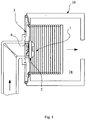
- the burner 1 comprises a burner body 2 with a burner head 3, downstream of which the combustion of the air-gas mixture takes place; the air-gas mixture is supplied to the burner, for example, by means of a fan, not shown.
- the burner is arranged to be housed in a combustion chamber 1a, shown only schematically, of a heating apparatus, which also houses a heat exchanger device 1b inside which an operative fluid circulates and is heated by means of the burner.
- the combustion chamber 1a is delimited and sealed in an openable manner by a shutter element, indicated 5, having the configuration of a plate-like, disk-shaped base.
- the shutter element 5 has a central through aperture 6 in the region of which the burner body 2 is mounted.
- the combustible air-gas mixture directed towards the burner head 3 is supplied through the aperture, the configuration of which will be described in greater detail below.
- the burner body 2 also has an axially symmetrical cylindrical portion 7 which has a principal axis X and at one end of which an annular flange 8 is provided; the portion 7 is extended, at the opposite axial end, by a portion 9 with a conical wall defining the end portion of the burner head 3.
- the burner body is fixed to the shutter element 5, coaxially with the aperture 6, by means of the flange 8.
- the above-mentioned devices are constructed structurally independently of one another and the flashback prevention device is advantageously arranged downstream of the flow guide device.
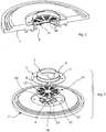
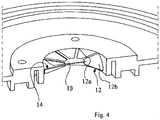
- the flow guide device 10 is produced integrally with the shutter element 5, in the region of the aperture 6. More particularly, the flow guide device comprises a plurality of radial deflector fins 12 which are integral with the shutter and spaced apart angularly at regular intervals, with a spoke-like arrangement extending from a central support zone 13 which forms part of the shutter element and extends in the region of the axis X.
- the fins 12 are preferably inclined to the axial direction of the flow through the head so as to impart a rotational component to the flow that is conveyed through respective passageway sections 14 which are defined between each pair of adjacent fins 12.
- the sections 14 are defined within the through aperture 6 formed in the shutter element.
- each fin 12 comprises a first surface portion 12a which extends radially between the support 13 and a circumferential edge of the aperture 6, and a second surface portion 12b which forms an extension of the first portion and is inclined to the axis X, as shown in the drawings.
- each fin also has a substantially flat surface which is inclined at 45° to a plane perpendicular to the axis X.
- the flash-back prevention device comprises a plate-like element 15 provided with a plurality of through apertures 16 which extend through its thickness and have a slot-like and/or circular shape in accordance with a preselected configuration, and through which the air-gas mixture intended for combustion on the surface of the head is supplied.
- the configuration of the apertures 16 is also selected so as to prevent flash-back when the burner is operating at low power and thus to ensure stable attachment of the flame to the burner.
- the plate-like element 15 has a flat, disk-like configuration and is formed so as to be structurally independent of the burner body and is capable of being held thereon by being interposed between the shutter element and the flange of the burner body, the fixing of the flange to the shutter holding the flash-back prevention device in position.
- the element 15 may be made of blanked sheet metal with apertures 16 formed by drilling or punching.
- the air-gas reagent mixture premixed upstream of the burner head 3, is supplied through the sections 14 of the aperture 6 and is deflected beforehand by the inclined profiles of the deflector fins 12.
- a reduced pressure is created which, in predetermined conditions, can draw the flow back into the burner, thus forming a toroidal recirculation bubble which serves to stabilize the flame and to reduce the average temperature of the flame front, thus reducing nitrogen oxide emissions (NOx).
- NOx nitrogen oxide emissions
- the operation of the burner is the typical operation of a recirculation burner with a predetermined number of "swirls" and this operation is typical, within the modulation range, as the power is gradually increased, up to the maximum power permitted for the burner.
- the reduced pressure in the centre of the burner can no longer draw the flow back towards it and the burner tends to operate as a conventional premix burner without recirculation.
- the burner is not subject to problems due to flash-back, by virtue of the operation of the flash-back prevention device provided in the burner, or to problems of instability owing to flame detachment, by virtue of the stabilizing function of the same device.
- the burner can adapt to the combustion regime, within the modulation range in which it is used, as the burnt power varies.
- a taper is provided in the side wall of the burner body (the conical portion 9) as described above. The presence of this conical wall creates a flame anchorage zone and thus renders the transition between the two combustion regimes stable.
- the flow guide device is formed integrally with the shutter element, the number of components to be produced and assembled is advantageously reduced with consequent easier and quicker assembly of the burner. In fact it is necessary merely to fix of the burner head to the shutter element with the preliminary interposition of the flash-back prevention device to complete the assembly of the burner.
Landscapes
- Engineering & Computer Science (AREA)
- Chemical & Material Sciences (AREA)
- Combustion & Propulsion (AREA)
- Mechanical Engineering (AREA)
- General Engineering & Computer Science (AREA)
- Gas Burners (AREA)
- Pre-Mixing And Non-Premixing Gas Burner (AREA)
Claims (8)
- Modulierender Gasbrenner, der zum Betrieb zum Vormischen eines brennbaren Luft-Gas-Gemisches ausgebildet ist, umfassend:- einen Brennerkörper (2), der auf einem Verschlusselement (5) zum Abdichten einer Brennkammer (1a) des Brenners im Bereich einer Durchgangsöffnung (6) im Verschluss (5) befestigt ist, durch die das brennbare Gemisch dem Brenner zugeführt wird,- einen Brennerkopf (3), zu dem das brennbare Luft-Gas-Gemisch, das in die Brennkammer (1a) durch die Öffnung (6) eingeleitet wird, zugeführt werden kann,- eine Vorrichtung (10) zum Führen der Strömung des Gemisches, die rotatorische Komponenten auf die Strömungsgeschwindigkeit zum Brennerkopf (3) weitergibt,- eine Flammenrückschlag-Verhinderungsvorrichtung, die im Brennerkopf (3) positioniert ist, wobei die Energie am Brenner innerhalb eines vorbestimmten Modulationsbereichs zwischen einem minimalen Energiezustand, bei dem der Brenner überwiegend in der Weise eines Vormischbrenners ohne Flammentrennung oder Flammenrückschlag in Betrieb ist, und einem maximalen Energiezustand, bei dem der Brenner vorwiegend in der Weise eines Brenners mit einer Rückführung der Strömungen der Reagenzien des brennbaren Gemisches in Betrieb ist, moduliert wird, wobei die Srömungsführungsvorrichtung strukturell unabhängig von der Flammenrückschlag-Verhinderungsvorrichtung ist,- wobei die Srömungsführungsvorrichtung (10) einstückig mit dem Verschlusselement (5) im Bereich der Durchgangsöffnung (6) hergestellt ist,- wobei die Srömungsführungsvorrichtung eine Mehrzahl von radialen Ablenkrippen (12) aufweist, die mit dem Verschlusselement (5) einstückig sind und innerhalb der Durchgangsöffnung (6) des Abschlusselements (5) ausgebildet sind,- wobei die Rippen (12) umfangsmäßig beabstandet sind und zur axialen Richtung (X) der Strömung durch den Kopf (3) geneigt sind, um so eine rotatorische Komponente auf die Strömung weiterzugeben, die durch jeweilige Durchgangsabschnitte (14) geleitet wird, die zwischen jedem Paar von benachbarten Rippen (12) ausgebildet sind, und- wobei der Brennerkörper (2) einen rohrförmigen Bereich (7) mit einer zylindrischen Wand aufweist, der an einem seiner axialen Enden einen Flansch (8) zur Verbindung mit dem Verschlusselement (5) aufweist, und am gegenüberliegenden axialen Ende durch einen Bereich mit einer konischen Wand erweitert sind,- wobei der Körper (2) am Verschlusselement (5) mittels des Flansches (8) mit der Zwischenanordnung der Flammenrückschlags-Verhinderungsvorrichtung fixiert ist.
- Brenner gemäß Anspruch 1, in dem sich die Rippen (12) in den Bereich des Kopfes (3) mit regelmäßigen Winkelabständen erstrecken.
- Brenner gemäß Anspruch 2, in dem jede Rippe (12) einen ersten Flächenbereich (12a) aufweist, der sich radial zwischen einem mittleren Abstützbereich des Verschlusselements (5), das darin mit der Durchgangsöffnung (6) koaxial ist, und einer Umfangskante des Abschlusselements erstreckt, und einen zweiten Flächenbereich (12b) aufweist, der eine Erweiterung des ersten Bereichs bildet und zur Achse des rohrförmigen Brennerkörpers (2) geneigt ist.
- Brenner gemäß Anspruch 3, in dem der zweite Flächenbereich (12b) von jeder Rippe (12) eine im Wesentlichen ebene Fläche aufweist.
- Brenner gemäß Anspruch 1, in dem der zweite Flächenbereich (12b) von jeder Rippe (12) um ungefähr 45° zu einer Fläche geneigt ist, die zur Hauptachse (X) der Durchgangsöffnung (6) senkrecht ist.
- Brenner gemäß einem der vorhergehenden Ansprüche, in dem die Flammenrückschlags-Verhinderungsvorrichtung ein plattenförmiges Element (15) aufweist, das mit einer Mehrzahl von Durchgangsöffnungen (16) versehen ist, die sich durch ihre Querdicke für den Durchgang des brennbaren Gemisches durch den Kopf (3) erstreckt.
- Brenner gemäß Anspruch 6, in dem das plattenförmige Element (15) eine ebene scheibenförmige Konfiguration aufweist.
- Brenner gemäß Anspruch 6 oder 7, in dem das Element (15) aus gestanztem Metallblech hergestellt ist und die Durchgangsöffnungen (16) durch Bohren oder Stanzen ausgebildet sind.
Applications Claiming Priority (2)
| Application Number | Priority Date | Filing Date | Title |
|---|---|---|---|
| ITPD2008A000381A IT1392713B1 (it) | 2008-12-23 | 2008-12-23 | Bruciatore a gas con pre-miscelazione |
| PCT/IT2009/000566 WO2010073282A1 (en) | 2008-12-23 | 2009-12-16 | A premix gas burner |
Publications (2)
| Publication Number | Publication Date |
|---|---|
| EP2368069A1 EP2368069A1 (de) | 2011-09-28 |
| EP2368069B1 true EP2368069B1 (de) | 2017-07-26 |
Family
ID=41261671
Family Applications (1)
| Application Number | Title | Priority Date | Filing Date |
|---|---|---|---|
| EP09807503.9A Not-in-force EP2368069B1 (de) | 2008-12-23 | 2009-12-16 | Vormischgasbrenner |
Country Status (3)
| Country | Link |
|---|---|
| EP (1) | EP2368069B1 (de) |
| IT (1) | IT1392713B1 (de) |
| WO (1) | WO2010073282A1 (de) |
Cited By (2)
| Publication number | Priority date | Publication date | Assignee | Title |
|---|---|---|---|---|
| CN107969144A (zh) * | 2015-05-14 | 2018-04-27 | 烈骑有限责任公司 | 具有流动分配部件的燃烧器 |
| CN111033123A (zh) * | 2017-06-19 | 2020-04-17 | 塞拉斯热能技术有限责任公司 | 用于改变不同腔之间的过渡流动效应的挡板组件 |
Families Citing this family (6)
| Publication number | Priority date | Publication date | Assignee | Title |
|---|---|---|---|---|
| DE202017100629U1 (de) * | 2017-02-07 | 2017-02-20 | Palux Aktiengesellschaft | Gasbrennervorrichtung für einen Wärmetauscher |
| CN112128805A (zh) * | 2020-11-03 | 2020-12-25 | 中国科学院大连化学物理研究所 | 一种燃气灶 |
| US12474047B2 (en) | 2020-11-03 | 2025-11-18 | Dalian Institute Of Chemical Physics, Chinese Academy Of Sciences | Burner and applications thereof |
| CN112212328B (zh) * | 2020-11-03 | 2025-12-23 | 中国科学院大连化学物理研究所 | 燃烧器及其应用 |
| EP4006417B1 (de) * | 2020-11-30 | 2023-08-16 | Beckett Thermal Solutions S.R.L. | Brennermembran für einen brenner |
| US20240102649A1 (en) * | 2022-09-28 | 2024-03-28 | Honeywell International Inc. | Fuel-air mixing and flame stabilization device for a low emission burner with internal flue gas recirculation |
Citations (1)
| Publication number | Priority date | Publication date | Assignee | Title |
|---|---|---|---|---|
| EP2242952B1 (de) * | 2008-01-21 | 2015-01-07 | Sit La Precisa S.p.A. con socio unico | Vormischgasbrenner |
Family Cites Families (3)
| Publication number | Priority date | Publication date | Assignee | Title |
|---|---|---|---|---|
| DE3604314A1 (de) * | 1986-02-12 | 1987-08-13 | Webasto Werk Baier Kg W | Heizgeraet, insbesondere zusatzheizgeraet |
| US5567147A (en) * | 1995-06-07 | 1996-10-22 | Frontier, Inc. | Burner for burning apparatus |
| US20050227195A1 (en) * | 2004-04-08 | 2005-10-13 | George Kenneth R | Combustion burner assembly having low oxides of nitrogen emission |
-
2008
- 2008-12-23 IT ITPD2008A000381A patent/IT1392713B1/it active
-
2009
- 2009-12-16 EP EP09807503.9A patent/EP2368069B1/de not_active Not-in-force
- 2009-12-16 WO PCT/IT2009/000566 patent/WO2010073282A1/en not_active Ceased
Patent Citations (1)
| Publication number | Priority date | Publication date | Assignee | Title |
|---|---|---|---|---|
| EP2242952B1 (de) * | 2008-01-21 | 2015-01-07 | Sit La Precisa S.p.A. con socio unico | Vormischgasbrenner |
Cited By (5)
| Publication number | Priority date | Publication date | Assignee | Title |
|---|---|---|---|---|
| CN107969144A (zh) * | 2015-05-14 | 2018-04-27 | 烈骑有限责任公司 | 具有流动分配部件的燃烧器 |
| CN111033123A (zh) * | 2017-06-19 | 2020-04-17 | 塞拉斯热能技术有限责任公司 | 用于改变不同腔之间的过渡流动效应的挡板组件 |
| CN111033123B (zh) * | 2017-06-19 | 2022-08-23 | 塞拉斯热能技术有限责任公司 | 用于改变不同腔之间的过渡流动效应的挡板组件 |
| US11530711B2 (en) | 2017-06-19 | 2022-12-20 | Selas Heat Technology Company Llc | Baffle assembly for modifying transitional flow effects between different cavities |
| EP3642537B1 (de) * | 2017-06-19 | 2024-11-13 | Selas Heat Technology Company LLC | Ablenkanordnung zum modifizieren von übergangsströmungseffekten zwischen verschiedenen hohlräumen |
Also Published As
| Publication number | Publication date |
|---|---|
| WO2010073282A1 (en) | 2010-07-01 |
| EP2368069A1 (de) | 2011-09-28 |
| ITPD20080381A1 (it) | 2010-06-24 |
| IT1392713B1 (it) | 2012-03-16 |
Similar Documents
| Publication | Publication Date | Title |
|---|---|---|
| EP2368069B1 (de) | Vormischgasbrenner | |
| CA2143232C (en) | A fuel nozzle for a turbine having dual capability for diffusion and premix combustion and methods of operation | |
| EP2886956B1 (de) | Festbrennstoffbrenner | |
| US6036481A (en) | Burner with flame retainer insert | |
| US6024083A (en) | Radiant tube burner nozzle | |
| US20030077551A1 (en) | Micro inshot burner | |
| EP3152490B1 (de) | Nicht symmetrischer brenner mit niedrigem nox-gehalt und verfahren | |
| EP2242952B1 (de) | Vormischgasbrenner | |
| US20120178032A1 (en) | Low NOx Gas Burners With Carryover Ignition | |
| EP1209415A2 (de) | Rohrförmiger Brenner | |
| US20030138749A1 (en) | Burner plaque | |
| US11397026B2 (en) | Burner for gas-fired furnace | |
| RU2526097C2 (ru) | Промышленная горелка и соответствующий способ сгорания для термической печи | |
| JP2008232619A (ja) | ガスコンロ | |
| EP3926236A2 (de) | Portierter brenner | |
| KR100420002B1 (ko) | 예혼합 메탈화이버 버너 | |
| EP3364105B1 (de) | Brenner für niederkalorische brennstoffe | |
| EP4413298A1 (de) | Brennerdeck und verfahren zu seiner herstellung | |
| US11808448B2 (en) | Burner assemblies for a cooktop | |
| EP4365490B1 (de) | Endvorrichtung mit progressivem brennerkopf für niedrige nox-emissionen und brenner mit dieser endvorrichtung | |
| US20250198617A1 (en) | Burner device | |
| KR101971606B1 (ko) | 배기가스가 재순환되는 저 질소산화물 연소기 | |
| KR20250005437A (ko) | 폭연 방지 및 폭발 방지 표면 연소 가스 버너 | |
| WO2023280923A1 (en) | Premix gas burner system and method | |
| JPH04353308A (ja) | コンロバーナ |
Legal Events
| Date | Code | Title | Description |
|---|---|---|---|
| PUAI | Public reference made under article 153(3) epc to a published international application that has entered the european phase |
Free format text: ORIGINAL CODE: 0009012 |
|
| 17P | Request for examination filed |
Effective date: 20110526 |
|
| AK | Designated contracting states |
Kind code of ref document: A1 Designated state(s): AT BE BG CH CY CZ DE DK EE ES FI FR GB GR HR HU IE IS IT LI LT LU LV MC MK MT NL NO PL PT RO SE SI SK SM TR |
|
| DAX | Request for extension of the european patent (deleted) | ||
| 111Z | Information provided on other rights and legal means of execution |
Free format text: AT BE BG CH CY CZ DE DK EE ES FI FR GB GR HR HU IE IS IT LT LU LV MC MK MT NL NO PL PT RO SE SI SK SM TR Effective date: 20150129 |
|
| RAP1 | Party data changed (applicant data changed or rights of an application transferred) |
Owner name: SIT S.P.A. |
|
| 17Q | First examination report despatched |
Effective date: 20160324 |
|
| GRAP | Despatch of communication of intention to grant a patent |
Free format text: ORIGINAL CODE: EPIDOSNIGR1 |
|
| INTG | Intention to grant announced |
Effective date: 20170301 |
|
| GRAS | Grant fee paid |
Free format text: ORIGINAL CODE: EPIDOSNIGR3 |
|
| GRAA | (expected) grant |
Free format text: ORIGINAL CODE: 0009210 |
|
| AK | Designated contracting states |
Kind code of ref document: B1 Designated state(s): AT BE BG CH CY CZ DE DK EE ES FI FR GB GR HR HU IE IS IT LI LT LU LV MC MK MT NL NO PL PT RO SE SI SK SM TR |
|
| REG | Reference to a national code |
Ref country code: GB Ref legal event code: FG4D |
|
| REG | Reference to a national code |
Ref country code: CH Ref legal event code: EP |
|
| REG | Reference to a national code |
Ref country code: AT Ref legal event code: REF Ref document number: 912689 Country of ref document: AT Kind code of ref document: T Effective date: 20170815 |
|
| REG | Reference to a national code |
Ref country code: IE Ref legal event code: FG4D |
|
| REG | Reference to a national code |
Ref country code: DE Ref legal event code: R096 Ref document number: 602009047402 Country of ref document: DE |
|
| REG | Reference to a national code |
Ref country code: NL Ref legal event code: FP |
|
| REG | Reference to a national code |
Ref country code: LT Ref legal event code: MG4D |
|
| REG | Reference to a national code |
Ref country code: AT Ref legal event code: MK05 Ref document number: 912689 Country of ref document: AT Kind code of ref document: T Effective date: 20170726 |
|
| REG | Reference to a national code |
Ref country code: FR Ref legal event code: PLFP Year of fee payment: 9 |
|
| PG25 | Lapsed in a contracting state [announced via postgrant information from national office to epo] |
Ref country code: LT Free format text: LAPSE BECAUSE OF FAILURE TO SUBMIT A TRANSLATION OF THE DESCRIPTION OR TO PAY THE FEE WITHIN THE PRESCRIBED TIME-LIMIT Effective date: 20170726 Ref country code: FI Free format text: LAPSE BECAUSE OF FAILURE TO SUBMIT A TRANSLATION OF THE DESCRIPTION OR TO PAY THE FEE WITHIN THE PRESCRIBED TIME-LIMIT Effective date: 20170726 Ref country code: HR Free format text: LAPSE BECAUSE OF FAILURE TO SUBMIT A TRANSLATION OF THE DESCRIPTION OR TO PAY THE FEE WITHIN THE PRESCRIBED TIME-LIMIT Effective date: 20170726 Ref country code: AT Free format text: LAPSE BECAUSE OF FAILURE TO SUBMIT A TRANSLATION OF THE DESCRIPTION OR TO PAY THE FEE WITHIN THE PRESCRIBED TIME-LIMIT Effective date: 20170726 Ref country code: SE Free format text: LAPSE BECAUSE OF FAILURE TO SUBMIT A TRANSLATION OF THE DESCRIPTION OR TO PAY THE FEE WITHIN THE PRESCRIBED TIME-LIMIT Effective date: 20170726 Ref country code: NO Free format text: LAPSE BECAUSE OF FAILURE TO SUBMIT A TRANSLATION OF THE DESCRIPTION OR TO PAY THE FEE WITHIN THE PRESCRIBED TIME-LIMIT Effective date: 20171026 |
|
| PG25 | Lapsed in a contracting state [announced via postgrant information from national office to epo] |
Ref country code: ES Free format text: LAPSE BECAUSE OF FAILURE TO SUBMIT A TRANSLATION OF THE DESCRIPTION OR TO PAY THE FEE WITHIN THE PRESCRIBED TIME-LIMIT Effective date: 20170726 Ref country code: IS Free format text: LAPSE BECAUSE OF FAILURE TO SUBMIT A TRANSLATION OF THE DESCRIPTION OR TO PAY THE FEE WITHIN THE PRESCRIBED TIME-LIMIT Effective date: 20171126 Ref country code: PL Free format text: LAPSE BECAUSE OF FAILURE TO SUBMIT A TRANSLATION OF THE DESCRIPTION OR TO PAY THE FEE WITHIN THE PRESCRIBED TIME-LIMIT Effective date: 20170726 Ref country code: GR Free format text: LAPSE BECAUSE OF FAILURE TO SUBMIT A TRANSLATION OF THE DESCRIPTION OR TO PAY THE FEE WITHIN THE PRESCRIBED TIME-LIMIT Effective date: 20171027 Ref country code: BG Free format text: LAPSE BECAUSE OF FAILURE TO SUBMIT A TRANSLATION OF THE DESCRIPTION OR TO PAY THE FEE WITHIN THE PRESCRIBED TIME-LIMIT Effective date: 20171026 Ref country code: LV Free format text: LAPSE BECAUSE OF FAILURE TO SUBMIT A TRANSLATION OF THE DESCRIPTION OR TO PAY THE FEE WITHIN THE PRESCRIBED TIME-LIMIT Effective date: 20170726 |
|
| PG25 | Lapsed in a contracting state [announced via postgrant information from national office to epo] |
Ref country code: CZ Free format text: LAPSE BECAUSE OF FAILURE TO SUBMIT A TRANSLATION OF THE DESCRIPTION OR TO PAY THE FEE WITHIN THE PRESCRIBED TIME-LIMIT Effective date: 20170726 Ref country code: RO Free format text: LAPSE BECAUSE OF FAILURE TO SUBMIT A TRANSLATION OF THE DESCRIPTION OR TO PAY THE FEE WITHIN THE PRESCRIBED TIME-LIMIT Effective date: 20170726 Ref country code: DK Free format text: LAPSE BECAUSE OF FAILURE TO SUBMIT A TRANSLATION OF THE DESCRIPTION OR TO PAY THE FEE WITHIN THE PRESCRIBED TIME-LIMIT Effective date: 20170726 |
|
| REG | Reference to a national code |
Ref country code: DE Ref legal event code: R097 Ref document number: 602009047402 Country of ref document: DE |
|
| PG25 | Lapsed in a contracting state [announced via postgrant information from national office to epo] |
Ref country code: SM Free format text: LAPSE BECAUSE OF FAILURE TO SUBMIT A TRANSLATION OF THE DESCRIPTION OR TO PAY THE FEE WITHIN THE PRESCRIBED TIME-LIMIT Effective date: 20170726 Ref country code: EE Free format text: LAPSE BECAUSE OF FAILURE TO SUBMIT A TRANSLATION OF THE DESCRIPTION OR TO PAY THE FEE WITHIN THE PRESCRIBED TIME-LIMIT Effective date: 20170726 Ref country code: SK Free format text: LAPSE BECAUSE OF FAILURE TO SUBMIT A TRANSLATION OF THE DESCRIPTION OR TO PAY THE FEE WITHIN THE PRESCRIBED TIME-LIMIT Effective date: 20170726 |
|
| PLBE | No opposition filed within time limit |
Free format text: ORIGINAL CODE: 0009261 |
|
| STAA | Information on the status of an ep patent application or granted ep patent |
Free format text: STATUS: NO OPPOSITION FILED WITHIN TIME LIMIT |
|
| 26N | No opposition filed |
Effective date: 20180430 |
|
| REG | Reference to a national code |
Ref country code: CH Ref legal event code: PL |
|
| PG25 | Lapsed in a contracting state [announced via postgrant information from national office to epo] |
Ref country code: SI Free format text: LAPSE BECAUSE OF FAILURE TO SUBMIT A TRANSLATION OF THE DESCRIPTION OR TO PAY THE FEE WITHIN THE PRESCRIBED TIME-LIMIT Effective date: 20170726 |
|
| REG | Reference to a national code |
Ref country code: IE Ref legal event code: MM4A |
|
| PG25 | Lapsed in a contracting state [announced via postgrant information from national office to epo] |
Ref country code: LU Free format text: LAPSE BECAUSE OF NON-PAYMENT OF DUE FEES Effective date: 20171216 Ref country code: MT Free format text: LAPSE BECAUSE OF NON-PAYMENT OF DUE FEES Effective date: 20171216 |
|
| REG | Reference to a national code |
Ref country code: BE Ref legal event code: MM Effective date: 20171231 |
|
| PG25 | Lapsed in a contracting state [announced via postgrant information from national office to epo] |
Ref country code: IE Free format text: LAPSE BECAUSE OF NON-PAYMENT OF DUE FEES Effective date: 20171216 |
|
| PG25 | Lapsed in a contracting state [announced via postgrant information from national office to epo] |
Ref country code: LI Free format text: LAPSE BECAUSE OF NON-PAYMENT OF DUE FEES Effective date: 20171231 Ref country code: BE Free format text: LAPSE BECAUSE OF NON-PAYMENT OF DUE FEES Effective date: 20171231 Ref country code: CH Free format text: LAPSE BECAUSE OF NON-PAYMENT OF DUE FEES Effective date: 20171231 |
|
| PG25 | Lapsed in a contracting state [announced via postgrant information from national office to epo] |
Ref country code: MC Free format text: LAPSE BECAUSE OF FAILURE TO SUBMIT A TRANSLATION OF THE DESCRIPTION OR TO PAY THE FEE WITHIN THE PRESCRIBED TIME-LIMIT Effective date: 20170726 Ref country code: HU Free format text: LAPSE BECAUSE OF FAILURE TO SUBMIT A TRANSLATION OF THE DESCRIPTION OR TO PAY THE FEE WITHIN THE PRESCRIBED TIME-LIMIT; INVALID AB INITIO Effective date: 20091216 |
|
| PG25 | Lapsed in a contracting state [announced via postgrant information from national office to epo] |
Ref country code: CY Free format text: LAPSE BECAUSE OF NON-PAYMENT OF DUE FEES Effective date: 20170726 |
|
| PG25 | Lapsed in a contracting state [announced via postgrant information from national office to epo] |
Ref country code: MK Free format text: LAPSE BECAUSE OF FAILURE TO SUBMIT A TRANSLATION OF THE DESCRIPTION OR TO PAY THE FEE WITHIN THE PRESCRIBED TIME-LIMIT Effective date: 20170726 |
|
| PGFP | Annual fee paid to national office [announced via postgrant information from national office to epo] |
Ref country code: NL Payment date: 20191219 Year of fee payment: 11 |
|
| PGFP | Annual fee paid to national office [announced via postgrant information from national office to epo] |
Ref country code: FR Payment date: 20191220 Year of fee payment: 11 Ref country code: IT Payment date: 20191209 Year of fee payment: 11 |
|
| PG25 | Lapsed in a contracting state [announced via postgrant information from national office to epo] |
Ref country code: TR Free format text: LAPSE BECAUSE OF FAILURE TO SUBMIT A TRANSLATION OF THE DESCRIPTION OR TO PAY THE FEE WITHIN THE PRESCRIBED TIME-LIMIT Effective date: 20170726 |
|
| PGFP | Annual fee paid to national office [announced via postgrant information from national office to epo] |
Ref country code: DE Payment date: 20191219 Year of fee payment: 11 Ref country code: GB Payment date: 20191220 Year of fee payment: 11 |
|
| PG25 | Lapsed in a contracting state [announced via postgrant information from national office to epo] |
Ref country code: PT Free format text: LAPSE BECAUSE OF FAILURE TO SUBMIT A TRANSLATION OF THE DESCRIPTION OR TO PAY THE FEE WITHIN THE PRESCRIBED TIME-LIMIT Effective date: 20170726 |
|
| REG | Reference to a national code |
Ref country code: DE Ref legal event code: R119 Ref document number: 602009047402 Country of ref document: DE |
|
| REG | Reference to a national code |
Ref country code: NL Ref legal event code: MM Effective date: 20210101 |
|
| GBPC | Gb: european patent ceased through non-payment of renewal fee |
Effective date: 20201216 |
|
| PG25 | Lapsed in a contracting state [announced via postgrant information from national office to epo] |
Ref country code: NL Free format text: LAPSE BECAUSE OF NON-PAYMENT OF DUE FEES Effective date: 20210101 |
|
| PG25 | Lapsed in a contracting state [announced via postgrant information from national office to epo] |
Ref country code: FR Free format text: LAPSE BECAUSE OF NON-PAYMENT OF DUE FEES Effective date: 20201231 Ref country code: IT Free format text: LAPSE BECAUSE OF NON-PAYMENT OF DUE FEES Effective date: 20201216 |
|
| PG25 | Lapsed in a contracting state [announced via postgrant information from national office to epo] |
Ref country code: GB Free format text: LAPSE BECAUSE OF NON-PAYMENT OF DUE FEES Effective date: 20201216 Ref country code: DE Free format text: LAPSE BECAUSE OF NON-PAYMENT OF DUE FEES Effective date: 20210701 |