EP2242952B1 - Vormischgasbrenner - Google Patents
Vormischgasbrenner Download PDFInfo
- Publication number
- EP2242952B1 EP2242952B1 EP09703543.0A EP09703543A EP2242952B1 EP 2242952 B1 EP2242952 B1 EP 2242952B1 EP 09703543 A EP09703543 A EP 09703543A EP 2242952 B1 EP2242952 B1 EP 2242952B1
- Authority
- EP
- European Patent Office
- Prior art keywords
- burner
- head
- flow
- burner according
- flash
- Prior art date
- Legal status (The legal status is an assumption and is not a legal conclusion. Google has not performed a legal analysis and makes no representation as to the accuracy of the status listed.)
- Not-in-force
Links
Images


Classifications
-
- F—MECHANICAL ENGINEERING; LIGHTING; HEATING; WEAPONS; BLASTING
- F23—COMBUSTION APPARATUS; COMBUSTION PROCESSES
- F23D—BURNERS
- F23D14/00—Burners for combustion of a gas, e.g. of a gas stored under pressure as a liquid
- F23D14/46—Details
- F23D14/62—Mixing devices; Mixing tubes
-
- F—MECHANICAL ENGINEERING; LIGHTING; HEATING; WEAPONS; BLASTING
- F23—COMBUSTION APPARATUS; COMBUSTION PROCESSES
- F23C—METHODS OR APPARATUS FOR COMBUSTION USING FLUID FUEL OR SOLID FUEL SUSPENDED IN A CARRIER GAS OR AIR
- F23C9/00—Combustion apparatus characterised by arrangements for returning combustion products or flue gases to the combustion chamber
- F23C9/006—Combustion apparatus characterised by arrangements for returning combustion products or flue gases to the combustion chamber the recirculation taking place in the combustion chamber
-
- F—MECHANICAL ENGINEERING; LIGHTING; HEATING; WEAPONS; BLASTING
- F23—COMBUSTION APPARATUS; COMBUSTION PROCESSES
- F23D—BURNERS
- F23D14/00—Burners for combustion of a gas, e.g. of a gas stored under pressure as a liquid
- F23D14/46—Details
- F23D14/70—Baffles or like flow-disturbing devices
-
- F—MECHANICAL ENGINEERING; LIGHTING; HEATING; WEAPONS; BLASTING
- F23—COMBUSTION APPARATUS; COMBUSTION PROCESSES
- F23D—BURNERS
- F23D14/00—Burners for combustion of a gas, e.g. of a gas stored under pressure as a liquid
- F23D14/46—Details
- F23D14/72—Safety devices, e.g. operative in case of failure of gas supply
-
- F—MECHANICAL ENGINEERING; LIGHTING; HEATING; WEAPONS; BLASTING
- F23—COMBUSTION APPARATUS; COMBUSTION PROCESSES
- F23D—BURNERS
- F23D14/00—Burners for combustion of a gas, e.g. of a gas stored under pressure as a liquid
- F23D14/46—Details
- F23D14/72—Safety devices, e.g. operative in case of failure of gas supply
- F23D14/82—Preventing flashback or blowback
-
- F—MECHANICAL ENGINEERING; LIGHTING; HEATING; WEAPONS; BLASTING
- F23—COMBUSTION APPARATUS; COMBUSTION PROCESSES
- F23C—METHODS OR APPARATUS FOR COMBUSTION USING FLUID FUEL OR SOLID FUEL SUSPENDED IN A CARRIER GAS OR AIR
- F23C2202/00—Fluegas recirculation
- F23C2202/40—Inducing local whirls around flame
-
- F—MECHANICAL ENGINEERING; LIGHTING; HEATING; WEAPONS; BLASTING
- F23—COMBUSTION APPARATUS; COMBUSTION PROCESSES
- F23C—METHODS OR APPARATUS FOR COMBUSTION USING FLUID FUEL OR SOLID FUEL SUSPENDED IN A CARRIER GAS OR AIR
- F23C2900/00—Special features of, or arrangements for combustion apparatus using fluid fuels or solid fuels suspended in air; Combustion processes therefor
- F23C2900/07001—Air swirling vanes incorporating fuel injectors
-
- F—MECHANICAL ENGINEERING; LIGHTING; HEATING; WEAPONS; BLASTING
- F23—COMBUSTION APPARATUS; COMBUSTION PROCESSES
- F23D—BURNERS
- F23D2203/00—Gaseous fuel burners
- F23D2203/10—Flame diffusing means
- F23D2203/102—Flame diffusing means using perforated plates
-
- F—MECHANICAL ENGINEERING; LIGHTING; HEATING; WEAPONS; BLASTING
- F23—COMBUSTION APPARATUS; COMBUSTION PROCESSES
- F23D—BURNERS
- F23D2203/00—Gaseous fuel burners
- F23D2203/10—Flame diffusing means
- F23D2203/103—Flame diffusing means using screens
-
- F—MECHANICAL ENGINEERING; LIGHTING; HEATING; WEAPONS; BLASTING
- F23—COMBUSTION APPARATUS; COMBUSTION PROCESSES
- F23D—BURNERS
- F23D2209/00—Safety arrangements
- F23D2209/10—Flame flashback
-
- F—MECHANICAL ENGINEERING; LIGHTING; HEATING; WEAPONS; BLASTING
- F23—COMBUSTION APPARATUS; COMBUSTION PROCESSES
- F23D—BURNERS
- F23D2900/00—Special features of, or arrangements for burners using fluid fuels or solid fuels suspended in a carrier gas
- F23D2900/14—Special features of gas burners
- F23D2900/14021—Premixing burners with swirling or vortices creating means for fuel or air
-
- F—MECHANICAL ENGINEERING; LIGHTING; HEATING; WEAPONS; BLASTING
- F23—COMBUSTION APPARATUS; COMBUSTION PROCESSES
- F23D—BURNERS
- F23D2900/00—Special features of, or arrangements for burners using fluid fuels or solid fuels suspended in a carrier gas
- F23D2900/31019—Mixing tubes combined with burner heads
Definitions
- the present invention relates to a premix gas burner designed for operation with a premixing of a combustible air and gas mixture.
- the invention relates in particular to the specific technical field of modulating gas burners, in which the burner power can be modulated within a predetermined range of modulation, according to the specific operating requirements.
- combustion flame denotes a combustion process in which the reagents are mixed by fluid-dynamic action downstream of the burner head.
- premixed flame denotes a process in which the mixture is ready for burning when it reaches the burner head.
- a mixing phenomenon characterized by a mixing time
- a combustion phenomenon characterized by a combustion time
- the mixing time is zero and only the combustion time remains; therefore flames of this type generally have a higher velocity.
- a premixed flame takes up less space than a diffusion flame, for a given burner power, because the reaction is faster since it is independent of the mixing time.
- nitrogen oxide emissions are related to various aspects such as the mixing of the reagents, the time for which the combustion products remain in "hot spots", the general temperature within the flame, and the uniformity of the flame.
- the premixing of the reagents upstream of the burner head tends to eliminate the presence of "hot spots” in the combustion area and thus tends to make the temperature more uniform. This characteristic cannot be obtained with diffusion flames in which there is a lack of uniformity of the thermal field.
- Burners of this type are not widely used in the domestic field because of the limited range of modulation and because of the space taken up by the flame.
- the use of premix burners is preferred in condensation boilers.
- This type of burner has a valve and a mixing system upstream of the burner.
- modulation ratios 1 to 5 whilst limiting nitrogen oxides because the thermal field in the flame is made uniform and the periods spent in the combustion area are reduced.
- the possibility of providing wider modulation ranges, that is, of reducing the power at the burner head is dependent on the availability of a burner head with apertures that are designed to stabilize the flame above them and to eliminate the effects of flash-back or flame detachment.
- the problem underlying the present invention is that of providing a modulating burner of the above-mentioned type which is designed structurally and functionally to overcome the limitations discussed with reference to the prior art mentioned.
- a first embodiment of a burner in particular a modulating burner for combustible gas of the premixed type, formed in accordance with the present invention, is generally indicated 1.
- the burner 1 comprises a burner body 2 with a burner head 3 downstream of which the air and gas mixture that is supplied to the burner, for example, by means of a fan device, not shown, is burnt.
- the burner is designed to be housed in a combustion chamber, not shown, of a heating apparatus, also not shown, which also houses a heat exchanger within which a working fluid circulates and is heated by the burner.
- the burner body 2 comprises, at the end axially remote from the head 3, a connecting flange 4 for fixing the burner body to a shutter element which is provided for removably sealing the combustion chamber.
- the burner body has a first, cylindrical portion 5 which is axially symmetrical with a principal axis X and is extended axially by a second, tapered portion 6.
- the cylindrical shell portion 5 is connected, upstream of the tapered portion 6, to a front surface 7 of the head 3 extending transversely to the axis X.
- the tapered portion 6 has generatrices which converge towards the surface 7, as shown in Figure 3 ; the function of this taper is explained in detail in the following part of the description.
- This device may have a conventional system for injecting the combustible gas into the air flow supplied to the burner and may also be associated with a fan unit the intake end of which is supplied with an air and gas mixture which is thus subjected to premixing.
- the burner head 3 is also provided with a device for guiding the flow of the mixture, which device can impart rotational components to the velocity of the flow that is supplied through the burner head, as well as with a device for preventing flashback.
- a plurality of distributor compartments 9 are provided in the surface 7 of the head; the compartments extend below the profile of the surface 7 towards the flange 4 and are spaced apart from each other.
- the distributor compartments 9 are spaced at regular angular intervals and radiate from the centre of the circular surface 7 located on the axis X.
- Each compartment 9 is delimited by a pair of walls 9a, 9b which are interconnnected along an edge 10 which extends radially and is connected to the surface 7. At the ends radially remote from the axis X, the walls 9a, 9b are connected to a further lateral wall 11 which defines the corresponding compartment 9 jointly with them.
- each compartment 9 the walls 9a, 9b are inclined to one another to define an obtuse angle inside the compartment, about the edge 10, as shown in the drawings.
- each compartment 9 also has a plurality of slotted and/or circular through apertures 12 which are arranged in a preselected configuration and through which the air and gas mixture to be burnt on the surface 7 of the head is supplied.
- the configuration of the apertures 12 is also selected so as to prevent flash-back when the burner is operating at low power, thus ensuring stable attachment of the flame to the burner.
- the wall 9b is a solid wall and its inclination to the contiguous wall 9a is such that the flow of the mixture supplied through the head is diverted and a recirculation phenomenon is created by means of a rotational component imparted to the flow of reagents, as explained further below.
- the flow guide device which can cause the above-mentioned recirculation is thus formed by the plurality of walls 9b formed in the compartments 9 of the burner head 3.
- the flash-back prevention device is formed by the plurality of through apertures 12 in a suitable quantity and of suitable size, which are created in the plurality of walls 9a of the distributor compartments 9.
- the air and gas reagent mixture, premixed upstream of the burner head 3, is supplied through the apertures 12 of each distributor compartment 9 and is diverted by the inclined profile of the compartment.
- a low pressure region is thus created in the centre of the burner, in the area downstream of the head, as shown in the diagram of Figure 2 ; in certain conditions, the low pressure region can draw the flow into itself, thus forming a toroidal recirculation bubble which serves to stabilize the flame and reduce the mean temperature of the flame front, thus reducing nitrogen oxide (NOx) emissions.
- the burner operates in a manner typical of a recirculation burner with a predetermined number of "swirls" and this manner of operation is maintained, in the modulation range, as the power gradually increases up to the maximum power permitted for the burner.
- the burner is not affected by flash-back problems, by virtue of the operation of the flash-back prevention device provided in the burner, or by instability problems due to flame detachment, by virtue of the stabilizing function of the device.
- the burner can adapt to the combustion conditions as the burner power varies, in the range of modulation in which it is used.
- a fluid-dynamically unstable transition area may be present, with fluctuations of the reagent flow which may lead to pulsations or extinction of the flame during this phase.
- the lateral wall (portion 6) of the burner body is tapered, as described above. The presence of this tapered wall creates a flame attachment area and thus makes the transition between the two combustion conditions stable.
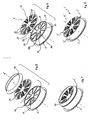
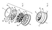
- a second embodiment of the burner is generally indicated 1'; in particular, this is a premix, modulating combustible gas burner formed in accordance with the present invention.
- this is a premix, modulating combustible gas burner formed in accordance with the present invention.
- details similar to those of the preceding embodiment are indicated, by the same reference numerals followed by an apostrophe (').
- the burner 1' comprises a burner body 2' with a burner head 3' downstream of which the air and gas mixture that is supplied to the burner, for example, by means of a fan device, not shown, is burnt.
- the burner is designed to be housed in a combustion chamber, not shown, of a heating apparatus, also not shown, which also houses a heat exchanger within which a working fluid circulates and is heated by the burner.
- the burner body 2' comprises, at the end axially remote from the head 3', a connecting flange 4' for fixing the burner body to a shutter element (not shown) which is provided for removably sealing the combustion chamber. More specifically, starting from the flange 4', the burner body 1' has a cylindrical portion 5' which is axially symmetrical with a principal axis X' and is connected, at its opposite end, to the front portion of the head 3' which extends transversely to the axis X'.
- This device may have a conventional system for injecting the combustible gas into the air flow supplied to the burner and may also be associated with a fan unit the intake end of which is supplied with an air and gas mixture which is thus subjected to premixing.
- the burner head 3' may also be provided with a device, generally indicated 20, for guiding the flow of the mixture, which device can impart rotational components to the velocity of the flow that is supplied through the burner head, as well as with a flash-back prevention device.
- a device generally indicated 20 for guiding the flow of the mixture, which device can impart rotational components to the velocity of the flow that is supplied through the burner head, as well as with a flash-back prevention device.
- the above-mentioned devices are constructed so as to be structurally independent of one another and the flash-back prevention device is advantageously arranged downstream of the flow guide device 20.
- the flow guide device 20 comprises a plurality of radial deflector fins 21 spaced at regular angular intervals and radiating from a central support area 22 extending in the region of the axis X'.
- the fins 21 are preferably inclined to the axial direction of the flow through the head so as to impart a rotational component to the flow that is conveyed through respective passageway sections 23 which are defined between each pair of adjacent fins 21.
- each fin 21 comprises a first surface portion 21a extending radially between the support 22 and the circumferential edge of the burner body and a second surface portion 21b which forms an extension of the first portion and is inclined to the axial direction X', as shown in the drawings.
- each fin 21b of each fin also has a substantially flat surface which is inclined at 45° to a plane perpendicular to the axis X'.
- the second surface portion 21b is also advantageously obtained by cutting and subsequent bending of a respective portion of a flat disk extending transversely to the axis X in the region of the burner head.
- This disk may be produced integrally with the tubular burner body 2' or, alternatively, may be structurally independent of the body 2' and connectible to the body by suitable connection means, for example, by welding along the circumferential edge.
- the flash-back prevention device comprises a plate-like element 24 provided with a plurality of slotted and/or circular through apertures 25 which extend through its thickness in a preselected configuration and through which the air and gas mixture to be burnt on the surface of the head is supplied.
- the configuration of the apertures 25 is also selected so as to prevent flash-back when the burner is operating at low power, thus ensuring stable attachment of the flame to the burner.
- the plate-like element 24 has a flat disk-like shape and is produced so as to be structurally independent of the burner body and to be fixable thereto, for example, by welding or clinching along the circumferential profile thereof.
- the element 24 may be made of blanked sheet-metal with apertures 25 produced by drilling or punching.
- the flash-back prevention device may be formed with a mesh structure, for example, with a metal mesh suitably connected to the burner along the circumferential profile of the tubular body 2'.
- the flash-back prevention device may be made of metal fibre.
- the burner body 2' has a lateral wall 26 with a tapered profile extending in the region of the front surface of the head and coaxial therewith. More particularly, the tapered wall 26, which converges towards the burner head 3', is provided downstream of the front surface of the head, with respect to the axial direction X' of the flow supplied to the head, as shown clearly in Figures 7 and 8 .
- the air and gas reagent mixture premixed upstream of the burner head 3' is supplied through the apertures 25 and is diverted beforehand by the inclined profiles of the deflector fins 21.
- a low pressure region is created in the centre of the burner, in the area downstream of the head; in certain conditions, the low pressure region can draw the flow into itself, thus forming a toroidal recirculation bubble which serves to stabilize the flame and reduce the mean temperature of the flame front, thus reducing nitrogen oxide (NOx) emissions.
- the burner operates in a manner typical of a recirculation burner with a predetermined number of "swirls" and this manner of operation is maintained, in the modulation range, as the power gradually increases up to the maximum power permitted for the burner.
- the burner is not affected by flash-back problems, by virtue of the operation of the flash-back prevention device provided in the burner, or by instability problems due to flame detachment, by virtue of the stabilizing function of the device.
- the burner can adapt to the combustion conditions as the burner power varies, in the modulation range in which it is used.
- a fluid-dynamically unstable transition area may be present with fluctuations of the reagent flow which may lead to pulsations or extinction of the flame during this phase.
- the lateral wall (wall 26) of the burner body is tapered, as described above. The presence of this tapered wall creates a flame attachment area and thus makes the transition between the two combustion conditions stable.
- a second device 27 for guiding the flow of mixture supplied through the burner head 3' is provided downstream of the flash-back prevention device.
- the second device 27 is structurally and functionally equivalent to the guide device 20 described above to which reference should be made for a detailed description.
- the device 27 also comprises a plurality of deflector fins, all of which are indicated 21 for simplicity, and which are structurally identical to those provided in the device 20.
- the fins 21 are connected to the outer circumferential edge by a ring 28 with a cylindrical wall which is intended to be connected to the cylindrical burner body 2'.
- the second guide device 27 provides an additional contribution to the rotational component imparted to the flow of the mixture.
- it since it is disposed downstream of the flash-back prevention device, it performs its function in an area in which flame is already present, in contrast with the guide device 20 which is active in a mixing area of the burner, in the absence of flame.
- a tapered lateral wall 26 is provided in the burner body 2' and extends in the region of the front surface of the head, coaxially therewith. More particularly, the tapered wall 26, which converges towards the burner head 3', is provided downstream of the second finned guide device 27, with respect to the axial direction X' of the flow supplied to the head 3', as is clearly shown in the respective drawings.
- the function of the tapered wall is substantially that already described above with reference to the embodiment of Figures 7 and 8 .
- the invention thus solves the problem posed, affording many advantages over known solutions.
- the dual operating conditions incorporated in the modulating boiler according to the invention afford, in the first place, a greater power modulation range and greater efficiency with lower nitrogen oxide emissions.
- the burner head of the burner according to the invention is less prone to overheating than conventional burners.
- the solution of the second embodiment described and of its variants also resolves the technological aspects of construction since the construction is much simpler, given the known sheet-metal processing techniques. This constructional simplicity also leads to reduced stressing of the various parts of the burner and hence to an increase in its life and strength.
Landscapes
- Engineering & Computer Science (AREA)
- Chemical & Material Sciences (AREA)
- Combustion & Propulsion (AREA)
- Mechanical Engineering (AREA)
- General Engineering & Computer Science (AREA)
- Gas Burners (AREA)
- Pre-Mixing And Non-Premixing Gas Burner (AREA)
Claims (20)
- Regulierender Gasbrenner (1; 1'), der zum Vormischbetrieb eines brennbaren Luft- und Gasgemisches eingerichtet ist, wobei der Brenner (1; 1') einen Brennerkopf (3; 3') aufweist, dem das brennbare Luft- und Gasgemisch zugeführt werden kann, eine Vorrichtung (6; 20) zum Leiten des Gemischstroms aufweist, wobei die Vorrichtung drehbare Komponenten für die Geschwindigkeit des Stroms zum Brennerkopf (3; 3') übermittelt, und eine Flammenrückschlag-Schutzvorrichtung (12; 24) aufweist, die im Brennerkopf (3; 3') positioniert ist, und zwar in der Weise, dass die Energie am Brenner innerhalb eines vorbestimmten Regelbereichs zwischen einem minimalen Energiezustand, in dem der Brenner (1; 1') überwiegend wie ein Vormischbrenner ohne Flammtrennung oder Flammenrückschlag in Betrieb ist, und einem maximalen Energiezustand reguliert werden kann, in dem der Brenner überwiegend wie ein Brenner mit Rückführung der Ströme der Reagenzien des brennbaren Gemisches in Betrieb ist, wobei der Brennerkopf (3) eine Mehrzahl von Abteilungen (9) zum Verteilen des brennbaren Gemisches aufweist, wobei die Abteilungen auf einer Oberfläche (7) des Kopfes (3) vorgesehen und voneinander beabstandet sind, wobei jede Abteilung durch zumindest eine erste Wand und eine zweite Wand (9a, 9b) abgegrenzt ist, die miteinander und mit der Oberfläche (7) des Kopfes verbunden sind, wobei die Wände (9a, 9b) zur Oberfläche (7) des Kopfes geneigt sind, wobei die erste Wand (9a) eine Mehrzahl von Durchflussöffnungen (12) für den Durchfluss des Gemisches durch den Kopf (3) aufweist, wobei die zweite Wand (9b) durchgehend und zur ersten Wand geneigt ist, um somit eine Drehkomponente für das Gemisch, das durch die Öffnungen (12) verteilt wird, bezüglich der Axialrichtung des Stroms durch den Kopf (3) zu übermitteln, wobei die Oberfläche (7) des Kopfes ein kreisförmiges Profil aufweist und sich die Mehrzahl von Abteilungen (9) über die Oberfläche (7) in regelmäßigen winkelförmigen Intervallen erstreckt, wobei der Brenner einen Brennerkörper (2) aufweist, der sich axial von einem Befestigungsflansch (4) zur Oberfläche des Kopfes erstreckt, wobei die seitliche Wand des Brennerkörpers (2) ein Profil aufweist, das am Bereich des Kopfes (3) verjüngt ist und mit dem kreisförmigen Profil des Brennerkopfes koaxial ist, und das verjüngte Profil der seitlichen Wand stromabwärts der vorderen Fläche (7) des Kopfes (3) bezüglich der Axialrichtung des Stroms, der dem Kopf zugeführt wird, vorgesehen ist.
- Brenner gemäß Anspruch 1, in dem die Stromführungsvorrichtung (6) durch die Mehrzahl von zweiten Wänden (9b) der Verteilungsabteilungen (9) ausgebildet ist.
- Brenner gemäß Anspruch 1, in dem die Flammenrückschlag-Schutzvorrichtung durch die Mehrzahl von Öffnungen (12) ausgebildet ist, die in den ersten Wänden (9a) der Verteilungsabteilungen (9) ausgebildet sind.
- Brenner gemäß Anspruch 1, in dem die Stromführungsvorrichtung (20) und die Flammenrückschlag-Schutzvorrichtung (24) strukturell unabhängig voneinander sind und die Flammenrückschlag-Schutzvorrichtung (24) stromabwärts der Stromführungsvorrichtung (20) bezüglich der Richtung des Stroms, der dem Brennerkopf (3; 3') zugeführt ist, angeordnet ist.
- Brenner gemäß Anspruch 4, in dem die Stromführungsvorrichtung (20) eine Mehrzahl von radialen Umlenkrippen (21) aufweist, die umfangsmäßig voneinander beabstandet sind, wobei die Rippen zur Axialrichtung des Stroms durch den Kopf (3') geneigt sind, um somit eine Drehkomponente zum Strom zu übermitteln, der durch jeweilige Durchgangsbereiche (23), die zwischen jedem Paar von benachbarten Rippen (21) ausgebildet sind, geleitet wird.
- Brenner gemäß Anspruch 5, in dem sich die Rippen (21) in den Bereich des Kopfes (3') in regelmäßigen winkelförmigen Intervallen erstreckt.
- Brenner gemäß Anspruch 6, der einen rohrförmigen Brennerkörper (2') aufweist, der an einem seiner Enden den Brennerkopf (3') trägt, wobei jede der Rippen (21) einen ersten Oberflächenbereich (21a), der sich radial zwischen einer mittleren Stütze (22), die mit dem rohrförmigen Körper koaxial ist, und einer Umfangskante des Körpers (2') erstreckt, und einen zweiten Oberflächenbereich (21b) aufweist, der eine Ausdehnung des ersten Bereichs bildet und zur Achse des rohrförmigen Brennerkörpers geneigt ist.
- Brenner gemäß Anspruch 7, in dem der zweite Oberflächenbereich (21b) jeder Rippe (21) eine im Wesentlichen ebene Oberfläche aufweist.
- Brenner gemäß Anspruch 8, in dem der zweite Oberflächenbereich jeder Rippe (21) um ungefähr 45° zu einer Ebene geneigt ist, die senkrecht zur Achse des rohrförmigen Brennerkörpers (2') ist.
- Brenner gemäß einem der Ansprüche 5 bis 9, in dem jede Umlenkrippe (21) durch Ausschneiden und Biegen eines Bereichs einer ebenen Scheibe, die sich in den Bereich des Brennerkopfs erstreckt, hergestellt ist, wobei die ebene Scheibe einstückig mit dem rohrförmigen Brennerkörper (2') an dem Ende davon, an dem der Brennerkopf vorgesehen ist, hergestellt ist.
- Brenner gemäß einem der Ansprüche 5 bis 9, in dem jede Umlenkrippe (21) durch Ausschneiden und Biegen eines Bereichs einer ebenen Scheibe hergestellt ist, die sich in den Bereich des Brennerkopfes erstreckt, und die ebene Scheibe, in dem die Rippen (21) ausgebildet sind, so konstruiert ist, um strukturell unabhängig vom rohrförmigen Brennerkörper (2') zu sein, wobei ein Verbindungsmittel für die Verbindung mit dem Brennerkörper vorgesehen ist.
- Brenner gemäß einem der Ansprüche 4 bis 11, in dem die Flammenrückschlag-Schutzvorrichtung ein plattenförmiges Element (24) aufweist, das mit einer Mehrzahl von Durchflussöffnungen (25) versehen ist, die sich durch seine diagonale Dicke für den Durchfluss des brennbaren Gemisches durch den Kopf (3') erstrecken.
- Brenner gemäß Anspruch 12, in dem das plattenförmige Element (24) eine scheibenförmige Konfiguration aufweist.
- Brenner gemäß Anspruch 12 oder 13, in dem das plattenförmige Element (24) eine ebene Konfiguration aufweist.
- Brenner gemäß Anspruch 14, in dem das plattenförmige Element (24) aus blankem Blech hergestellt ist und die Durchflussöffnungen (25) durch Bohren oder Stanzen ausgebildet sind.
- Brenner gemäß Anspruch 14, in dem das plattenförmige Element (24) der Flammenrückschlag-Schutzvorrichtung mit einer Netzstruktur konstruiert ist.
- Brenner gemäß Anspruch 14, in dem das plattenförmige Element (24) der Flammenrückschlag-Schutzvorrichtung aus Metallfasern hergestellt ist.
- Brenner gemäß einem der Ansprüche 4 bis 17, in dem der Brennerkörper (2') im Bereich des Kopfes (3') eine seitliche Wand (26) mit einem verjüngten Profil aufweist, das sich koaxial mit dem Brennerkopf erstreckt.
- Brenner gemäß Anspruch 18, in dem das verjüngte Profil der Wand (26) stromabwärts der Vorderfläche des Kopfes (3') bezüglich der Axialrichtung des Stroms, der dem Kopf zugeführt wird, vorgesehen ist.
- Brenner gemäß einem der Ansprüche 4 bis 19, der eine zweite Vorrichtung (27) zum Führen des Gemischstroms aufweist, dessen Vorrichtung Drehkomponenten für die Geschwindigkeit des Stroms zum Brennerkopf (3') übermittelt, und strukturell von der Führungsvorrichtung (26) verschieden ist und stromabwärts der Flammenrückschlag-Schutzvorrichtung (24) bezüglich der Richtung des Gemischstroms, der dem Brennerkopf (3') zugeführt wird, angeordnet ist.
Applications Claiming Priority (3)
| Application Number | Priority Date | Filing Date | Title |
|---|---|---|---|
| ITPD20080021 ITPD20080021A1 (it) | 2008-01-21 | 2008-01-21 | Bruciatore a gas a pre-miscelazione |
| ITPD20080112 ITPD20080112A1 (it) | 2008-04-09 | 2008-04-09 | Bruciatore a gas a pre-miscelazione |
| PCT/IT2009/000014 WO2009093278A2 (en) | 2008-01-21 | 2009-01-15 | A premix gas burner |
Publications (2)
| Publication Number | Publication Date |
|---|---|
| EP2242952A2 EP2242952A2 (de) | 2010-10-27 |
| EP2242952B1 true EP2242952B1 (de) | 2015-01-07 |
Family
ID=40901516
Family Applications (1)
| Application Number | Title | Priority Date | Filing Date |
|---|---|---|---|
| EP09703543.0A Not-in-force EP2242952B1 (de) | 2008-01-21 | 2009-01-15 | Vormischgasbrenner |
Country Status (2)
| Country | Link |
|---|---|
| EP (1) | EP2242952B1 (de) |
| WO (1) | WO2009093278A2 (de) |
Cited By (2)
| Publication number | Priority date | Publication date | Assignee | Title |
|---|---|---|---|---|
| WO2016182778A1 (en) * | 2015-05-14 | 2016-11-17 | Lochinvar, Llc | Burner with flow distribution member |
| EP2368069B1 (de) * | 2008-12-23 | 2017-07-26 | Sit S.P.A. | Vormischgasbrenner |
Families Citing this family (2)
| Publication number | Priority date | Publication date | Assignee | Title |
|---|---|---|---|---|
| ITTO20100287A1 (it) * | 2010-04-13 | 2011-10-14 | Indesit Co Spa | Bruciatore per piano cottura, apparato di cottura comprendente tale bruciatore e metodo per la sua fabbricazione. |
| KR102378229B1 (ko) * | 2021-12-29 | 2022-03-25 | 주식회사 부-스타 | 효율적인 연료 혼합과 연소를 통해 질소산화물을 저감시키는 친환경 예혼합 가스버너 시스템 |
Family Cites Families (4)
| Publication number | Priority date | Publication date | Assignee | Title |
|---|---|---|---|---|
| US4872833A (en) * | 1988-05-16 | 1989-10-10 | A. O. Smith Corporation | Gas burner construction |
| US5407347A (en) * | 1993-07-16 | 1995-04-18 | Radian Corporation | Apparatus and method for reducing NOx, CO and hydrocarbon emissions when burning gaseous fuels |
| DE60333252D1 (de) * | 2003-03-24 | 2010-08-19 | Riello Spa | Luft/Brenngasmischer für Vormischbrenner, und Verbrennungssystem mit einem solchen Mischer |
| US20050227195A1 (en) * | 2004-04-08 | 2005-10-13 | George Kenneth R | Combustion burner assembly having low oxides of nitrogen emission |
-
2009
- 2009-01-15 EP EP09703543.0A patent/EP2242952B1/de not_active Not-in-force
- 2009-01-15 WO PCT/IT2009/000014 patent/WO2009093278A2/en not_active Ceased
Cited By (2)
| Publication number | Priority date | Publication date | Assignee | Title |
|---|---|---|---|---|
| EP2368069B1 (de) * | 2008-12-23 | 2017-07-26 | Sit S.P.A. | Vormischgasbrenner |
| WO2016182778A1 (en) * | 2015-05-14 | 2016-11-17 | Lochinvar, Llc | Burner with flow distribution member |
Also Published As
| Publication number | Publication date |
|---|---|
| WO2009093278A3 (en) | 2009-11-19 |
| WO2009093278A2 (en) | 2009-07-30 |
| EP2242952A2 (de) | 2010-10-27 |
Similar Documents
| Publication | Publication Date | Title |
|---|---|---|
| EP2368069B1 (de) | Vormischgasbrenner | |
| US20030143502A1 (en) | Large scale vortex devices for improved burner operation | |
| US10006628B2 (en) | Low NOx gas burners with carryover ignition | |
| US6050809A (en) | Immersion tube burner with improved flame stability | |
| EP2242952A2 (de) | Vormischgasbrenner | |
| KR100495505B1 (ko) | 다단제어를 구현하는 가스연소 버너 | |
| US7052273B2 (en) | Premixed fuel burner assembly | |
| US7063527B2 (en) | Burner plaque with continuous channels | |
| US20210123632A1 (en) | Burner for gas-fired furnace | |
| JP2004144467A (ja) | 分離された炎孔部を有する予混合ガス燃焼バーナ | |
| US9410698B2 (en) | Tubular burner | |
| JP2008232619A (ja) | ガスコンロ | |
| EP3926236A2 (de) | Portierter brenner | |
| KR100420002B1 (ko) | 예혼합 메탈화이버 버너 | |
| EP3315861B1 (de) | Gasbrenner | |
| EP4413298A1 (de) | Brennerdeck und verfahren zu seiner herstellung | |
| RU2860055C2 (ru) | Защищенная от дефлаграции и детонации газовая горелка поверхностного горения | |
| US20220163199A1 (en) | Burner assemblies for a cooktop | |
| CN222798986U (zh) | 燃烧器及烹饪器具 | |
| US20090220902A1 (en) | Burner for a heater with improved baffle plate | |
| JP2008520950A (ja) | 改良型燃料供給部、改良型遮熱板および改良型バッフルプレートを備えたヒータ用バーナ | |
| US8998605B2 (en) | Inshot burner flame retainer | |
| CN222798985U (zh) | 燃烧器及烹饪器具 | |
| AU2011239303B2 (en) | Tubular burner | |
| EP3825607B1 (de) | Modularer brenner |
Legal Events
| Date | Code | Title | Description |
|---|---|---|---|
| PUAI | Public reference made under article 153(3) epc to a published international application that has entered the european phase |
Free format text: ORIGINAL CODE: 0009012 |
|
| 17P | Request for examination filed |
Effective date: 20100813 |
|
| AK | Designated contracting states |
Kind code of ref document: A2 Designated state(s): AT BE BG CH CY CZ DE DK EE ES FI FR GB GR HR HU IE IS IT LI LT LU LV MC MK MT NL NO PL PT RO SE SI SK TR |
|
| AX | Request for extension of the european patent |
Extension state: AL BA RS |
|
| DAX | Request for extension of the european patent (deleted) | ||
| 17Q | First examination report despatched |
Effective date: 20140127 |
|
| GRAP | Despatch of communication of intention to grant a patent |
Free format text: ORIGINAL CODE: EPIDOSNIGR1 |
|
| INTG | Intention to grant announced |
Effective date: 20140902 |
|
| GRAS | Grant fee paid |
Free format text: ORIGINAL CODE: EPIDOSNIGR3 |
|
| GRAA | (expected) grant |
Free format text: ORIGINAL CODE: 0009210 |
|
| AK | Designated contracting states |
Kind code of ref document: B1 Designated state(s): AT BE BG CH CY CZ DE DK EE ES FI FR GB GR HR HU IE IS IT LI LT LU LV MC MK MT NL NO PL PT RO SE SI SK TR |
|
| REG | Reference to a national code |
Ref country code: GB Ref legal event code: FG4D |
|
| REG | Reference to a national code |
Ref country code: CH Ref legal event code: EP |
|
| REG | Reference to a national code |
Ref country code: IE Ref legal event code: FG4D |
|
| REG | Reference to a national code |
Ref country code: AT Ref legal event code: REF Ref document number: 705990 Country of ref document: AT Kind code of ref document: T Effective date: 20150215 |
|
| REG | Reference to a national code |
Ref country code: DE Ref legal event code: R096 Ref document number: 602009028800 Country of ref document: DE Effective date: 20150226 |
|
| RAP2 | Party data changed (patent owner data changed or rights of a patent transferred) |
Owner name: SIT S.P.A. |
|
| REG | Reference to a national code |
Ref country code: NL Ref legal event code: T3 |
|
| REG | Reference to a national code |
Ref country code: NL Ref legal event code: SD Effective date: 20150506 |
|
| REG | Reference to a national code |
Ref country code: GB Ref legal event code: 732E Free format text: REGISTERED BETWEEN 20150514 AND 20150520 |
|
| REG | Reference to a national code |
Ref country code: AT Ref legal event code: MK05 Ref document number: 705990 Country of ref document: AT Kind code of ref document: T Effective date: 20150107 |
|
| REG | Reference to a national code |
Ref country code: LT Ref legal event code: MG4D |
|
| PG25 | Lapsed in a contracting state [announced via postgrant information from national office to epo] |
Ref country code: BE Free format text: LAPSE BECAUSE OF NON-PAYMENT OF DUE FEES Effective date: 20150131 |
|
| PG25 | Lapsed in a contracting state [announced via postgrant information from national office to epo] |
Ref country code: BG Free format text: LAPSE BECAUSE OF FAILURE TO SUBMIT A TRANSLATION OF THE DESCRIPTION OR TO PAY THE FEE WITHIN THE PRESCRIBED TIME-LIMIT Effective date: 20150407 Ref country code: LT Free format text: LAPSE BECAUSE OF FAILURE TO SUBMIT A TRANSLATION OF THE DESCRIPTION OR TO PAY THE FEE WITHIN THE PRESCRIBED TIME-LIMIT Effective date: 20150107 Ref country code: NO Free format text: LAPSE BECAUSE OF FAILURE TO SUBMIT A TRANSLATION OF THE DESCRIPTION OR TO PAY THE FEE WITHIN THE PRESCRIBED TIME-LIMIT Effective date: 20150407 Ref country code: SE Free format text: LAPSE BECAUSE OF FAILURE TO SUBMIT A TRANSLATION OF THE DESCRIPTION OR TO PAY THE FEE WITHIN THE PRESCRIBED TIME-LIMIT Effective date: 20150107 Ref country code: HR Free format text: LAPSE BECAUSE OF FAILURE TO SUBMIT A TRANSLATION OF THE DESCRIPTION OR TO PAY THE FEE WITHIN THE PRESCRIBED TIME-LIMIT Effective date: 20150107 Ref country code: ES Free format text: LAPSE BECAUSE OF FAILURE TO SUBMIT A TRANSLATION OF THE DESCRIPTION OR TO PAY THE FEE WITHIN THE PRESCRIBED TIME-LIMIT Effective date: 20150107 Ref country code: FI Free format text: LAPSE BECAUSE OF FAILURE TO SUBMIT A TRANSLATION OF THE DESCRIPTION OR TO PAY THE FEE WITHIN THE PRESCRIBED TIME-LIMIT Effective date: 20150107 |
|
| REG | Reference to a national code |
Ref country code: CH Ref legal event code: PL |
|
| PG25 | Lapsed in a contracting state [announced via postgrant information from national office to epo] |
Ref country code: GR Free format text: LAPSE BECAUSE OF FAILURE TO SUBMIT A TRANSLATION OF THE DESCRIPTION OR TO PAY THE FEE WITHIN THE PRESCRIBED TIME-LIMIT Effective date: 20150408 Ref country code: LV Free format text: LAPSE BECAUSE OF FAILURE TO SUBMIT A TRANSLATION OF THE DESCRIPTION OR TO PAY THE FEE WITHIN THE PRESCRIBED TIME-LIMIT Effective date: 20150107 Ref country code: IS Free format text: LAPSE BECAUSE OF FAILURE TO SUBMIT A TRANSLATION OF THE DESCRIPTION OR TO PAY THE FEE WITHIN THE PRESCRIBED TIME-LIMIT Effective date: 20150507 Ref country code: PL Free format text: LAPSE BECAUSE OF FAILURE TO SUBMIT A TRANSLATION OF THE DESCRIPTION OR TO PAY THE FEE WITHIN THE PRESCRIBED TIME-LIMIT Effective date: 20150107 Ref country code: AT Free format text: LAPSE BECAUSE OF FAILURE TO SUBMIT A TRANSLATION OF THE DESCRIPTION OR TO PAY THE FEE WITHIN THE PRESCRIBED TIME-LIMIT Effective date: 20150107 |
|
| REG | Reference to a national code |
Ref country code: DE Ref legal event code: R097 Ref document number: 602009028800 Country of ref document: DE |
|
| PG25 | Lapsed in a contracting state [announced via postgrant information from national office to epo] |
Ref country code: MC Free format text: LAPSE BECAUSE OF FAILURE TO SUBMIT A TRANSLATION OF THE DESCRIPTION OR TO PAY THE FEE WITHIN THE PRESCRIBED TIME-LIMIT Effective date: 20150107 Ref country code: RO Free format text: LAPSE BECAUSE OF FAILURE TO SUBMIT A TRANSLATION OF THE DESCRIPTION OR TO PAY THE FEE WITHIN THE PRESCRIBED TIME-LIMIT Effective date: 20150107 Ref country code: SK Free format text: LAPSE BECAUSE OF FAILURE TO SUBMIT A TRANSLATION OF THE DESCRIPTION OR TO PAY THE FEE WITHIN THE PRESCRIBED TIME-LIMIT Effective date: 20150107 Ref country code: CH Free format text: LAPSE BECAUSE OF NON-PAYMENT OF DUE FEES Effective date: 20150131 Ref country code: LI Free format text: LAPSE BECAUSE OF NON-PAYMENT OF DUE FEES Effective date: 20150131 Ref country code: EE Free format text: LAPSE BECAUSE OF FAILURE TO SUBMIT A TRANSLATION OF THE DESCRIPTION OR TO PAY THE FEE WITHIN THE PRESCRIBED TIME-LIMIT Effective date: 20150107 Ref country code: DK Free format text: LAPSE BECAUSE OF FAILURE TO SUBMIT A TRANSLATION OF THE DESCRIPTION OR TO PAY THE FEE WITHIN THE PRESCRIBED TIME-LIMIT Effective date: 20150107 Ref country code: CZ Free format text: LAPSE BECAUSE OF FAILURE TO SUBMIT A TRANSLATION OF THE DESCRIPTION OR TO PAY THE FEE WITHIN THE PRESCRIBED TIME-LIMIT Effective date: 20150107 |
|
| REG | Reference to a national code |
Ref country code: IE Ref legal event code: MM4A |
|
| PLBE | No opposition filed within time limit |
Free format text: ORIGINAL CODE: 0009261 |
|
| STAA | Information on the status of an ep patent application or granted ep patent |
Free format text: STATUS: NO OPPOSITION FILED WITHIN TIME LIMIT |
|
| 26N | No opposition filed |
Effective date: 20151008 |
|
| REG | Reference to a national code |
Ref country code: FR Ref legal event code: ST Effective date: 20151117 |
|
| PG25 | Lapsed in a contracting state [announced via postgrant information from national office to epo] |
Ref country code: IE Free format text: LAPSE BECAUSE OF NON-PAYMENT OF DUE FEES Effective date: 20150115 |
|
| PG25 | Lapsed in a contracting state [announced via postgrant information from national office to epo] |
Ref country code: FR Free format text: LAPSE BECAUSE OF NON-PAYMENT OF DUE FEES Effective date: 20150309 Ref country code: SI Free format text: LAPSE BECAUSE OF FAILURE TO SUBMIT A TRANSLATION OF THE DESCRIPTION OR TO PAY THE FEE WITHIN THE PRESCRIBED TIME-LIMIT Effective date: 20150107 |
|
| PG25 | Lapsed in a contracting state [announced via postgrant information from national office to epo] |
Ref country code: BE Free format text: LAPSE BECAUSE OF FAILURE TO SUBMIT A TRANSLATION OF THE DESCRIPTION OR TO PAY THE FEE WITHIN THE PRESCRIBED TIME-LIMIT Effective date: 20150107 |
|
| PG25 | Lapsed in a contracting state [announced via postgrant information from national office to epo] |
Ref country code: MT Free format text: LAPSE BECAUSE OF FAILURE TO SUBMIT A TRANSLATION OF THE DESCRIPTION OR TO PAY THE FEE WITHIN THE PRESCRIBED TIME-LIMIT Effective date: 20150107 |
|
| PG25 | Lapsed in a contracting state [announced via postgrant information from national office to epo] |
Ref country code: HU Free format text: LAPSE BECAUSE OF FAILURE TO SUBMIT A TRANSLATION OF THE DESCRIPTION OR TO PAY THE FEE WITHIN THE PRESCRIBED TIME-LIMIT; INVALID AB INITIO Effective date: 20090115 |
|
| PG25 | Lapsed in a contracting state [announced via postgrant information from national office to epo] |
Ref country code: CY Free format text: LAPSE BECAUSE OF FAILURE TO SUBMIT A TRANSLATION OF THE DESCRIPTION OR TO PAY THE FEE WITHIN THE PRESCRIBED TIME-LIMIT Effective date: 20150107 |
|
| PG25 | Lapsed in a contracting state [announced via postgrant information from national office to epo] |
Ref country code: PT Free format text: LAPSE BECAUSE OF FAILURE TO SUBMIT A TRANSLATION OF THE DESCRIPTION OR TO PAY THE FEE WITHIN THE PRESCRIBED TIME-LIMIT Effective date: 20150507 |
|
| PG25 | Lapsed in a contracting state [announced via postgrant information from national office to epo] |
Ref country code: TR Free format text: LAPSE BECAUSE OF FAILURE TO SUBMIT A TRANSLATION OF THE DESCRIPTION OR TO PAY THE FEE WITHIN THE PRESCRIBED TIME-LIMIT Effective date: 20150107 |
|
| PG25 | Lapsed in a contracting state [announced via postgrant information from national office to epo] |
Ref country code: LU Free format text: LAPSE BECAUSE OF NON-PAYMENT OF DUE FEES Effective date: 20150115 |
|
| PG25 | Lapsed in a contracting state [announced via postgrant information from national office to epo] |
Ref country code: MK Free format text: LAPSE BECAUSE OF FAILURE TO SUBMIT A TRANSLATION OF THE DESCRIPTION OR TO PAY THE FEE WITHIN THE PRESCRIBED TIME-LIMIT Effective date: 20150107 |
|
| PGFP | Annual fee paid to national office [announced via postgrant information from national office to epo] |
Ref country code: NL Payment date: 20200121 Year of fee payment: 12 Ref country code: DE Payment date: 20200121 Year of fee payment: 12 Ref country code: IT Payment date: 20191217 Year of fee payment: 12 Ref country code: GB Payment date: 20200124 Year of fee payment: 12 |
|
| REG | Reference to a national code |
Ref country code: DE Ref legal event code: R119 Ref document number: 602009028800 Country of ref document: DE |
|
| REG | Reference to a national code |
Ref country code: NL Ref legal event code: MM Effective date: 20210201 |
|
| GBPC | Gb: european patent ceased through non-payment of renewal fee |
Effective date: 20210115 |
|
| PG25 | Lapsed in a contracting state [announced via postgrant information from national office to epo] |
Ref country code: NL Free format text: LAPSE BECAUSE OF NON-PAYMENT OF DUE FEES Effective date: 20210201 |
|
| PG25 | Lapsed in a contracting state [announced via postgrant information from national office to epo] |
Ref country code: DE Free format text: LAPSE BECAUSE OF NON-PAYMENT OF DUE FEES Effective date: 20210803 Ref country code: GB Free format text: LAPSE BECAUSE OF NON-PAYMENT OF DUE FEES Effective date: 20210115 |
|
| PG25 | Lapsed in a contracting state [announced via postgrant information from national office to epo] |
Ref country code: IT Free format text: LAPSE BECAUSE OF NON-PAYMENT OF DUE FEES Effective date: 20210115 |