EP2367708B1 - REFLEXIONSVORRICHTUNG MIT WEITEM SICHTWINKEL,REDUZIERTER VERZERRUNG UND& xA;ANAMORPHOSE UND REDUZIERTER VERDOPPLUNG REFLEKTIERTER BILDER,INSBESONDERE& xA;FÜR FAHRZEUGE - Google Patents
REFLEXIONSVORRICHTUNG MIT WEITEM SICHTWINKEL,REDUZIERTER VERZERRUNG UND& xA;ANAMORPHOSE UND REDUZIERTER VERDOPPLUNG REFLEKTIERTER BILDER,INSBESONDERE& xA;FÜR FAHRZEUGE Download PDFInfo
- Publication number
- EP2367708B1 EP2367708B1 EP09759944.3A EP09759944A EP2367708B1 EP 2367708 B1 EP2367708 B1 EP 2367708B1 EP 09759944 A EP09759944 A EP 09759944A EP 2367708 B1 EP2367708 B1 EP 2367708B1
- Authority
- EP
- European Patent Office
- Prior art keywords
- respect
- external surface
- internal surface
- reflecting device
- coefficients
- Prior art date
- Legal status (The legal status is an assumption and is not a legal conclusion. Google has not performed a legal analysis and makes no representation as to the accuracy of the status listed.)
- Active
Links
Images



Classifications
-
- B—PERFORMING OPERATIONS; TRANSPORTING
- B60—VEHICLES IN GENERAL
- B60R—VEHICLES, VEHICLE FITTINGS, OR VEHICLE PARTS, NOT OTHERWISE PROVIDED FOR
- B60R1/00—Optical viewing arrangements; Real-time viewing arrangements for drivers or passengers using optical image capturing systems, e.g. cameras or video systems specially adapted for use in or on vehicles
- B60R1/02—Rear-view mirror arrangements
- B60R1/08—Rear-view mirror arrangements involving special optical features, e.g. avoiding blind spots, e.g. convex mirrors; Side-by-side associations of rear-view and other mirrors
- B60R1/081—Rear-view mirror arrangements involving special optical features, e.g. avoiding blind spots, e.g. convex mirrors; Side-by-side associations of rear-view and other mirrors avoiding blind spots, e.g. by using a side-by-side association of mirrors
- B60R1/082—Rear-view mirror arrangements involving special optical features, e.g. avoiding blind spots, e.g. convex mirrors; Side-by-side associations of rear-view and other mirrors avoiding blind spots, e.g. by using a side-by-side association of mirrors using a single wide field mirror or an association of rigidly connected mirrors
-
- Y—GENERAL TAGGING OF NEW TECHNOLOGICAL DEVELOPMENTS; GENERAL TAGGING OF CROSS-SECTIONAL TECHNOLOGIES SPANNING OVER SEVERAL SECTIONS OF THE IPC; TECHNICAL SUBJECTS COVERED BY FORMER USPC CROSS-REFERENCE ART COLLECTIONS [XRACs] AND DIGESTS
- Y10—TECHNICAL SUBJECTS COVERED BY FORMER USPC
- Y10T—TECHNICAL SUBJECTS COVERED BY FORMER US CLASSIFICATION
- Y10T29/00—Metal working
- Y10T29/49—Method of mechanical manufacture
- Y10T29/49826—Assembling or joining
Definitions
- the present invention relates to a reflecting device with wide vision angle, reduced distortion and anamorphosis and reduced doubling of reflected images, used mainly as an external rear-view mirror for road and off-road vehicles.
- External reflecting devices for road and off-road vehicles are mounted laterally on either sides of the vehicle and are constituted generally by a flat reflecting surface or by a convex spherical surface.
- the directives for type-approval of rear-view mirrors that are in force in the various countries, if they allow the use of convex reflecting surfaces (for example European directive 2003/97/EC), set a minimum value of the radius of curvature in order to prevent the image generated by the device from being excessively small and having an excessively high level of distortion.
- distortion in fact depends directly on the value of the radius of curvature; since the radius is chosen according to the dimensions of the mirror and to the field that must be viewed, it is not possible to correct in any way distortion, much less anamorphosis, i.e., the transformation to which an image is subjected when a geometric deformation occurs for which the ratio between the horizontal dimension and the vertical dimension is not constant.
- the value of the minimum radius depends on the function performed by the mirror and on the directive itself; in any case, these reflecting devices, taking into account their usual dimensions, have a limited field of vision, approximately 20°, and accordingly have a rather wide blind spot, which often does not allow to show any approaching vehicles.
- These known reflecting devices are provided by arranging to the side of a first flat or spherical main surface a second spherical or aspherical convex surface which is highly curved.
- the overall field of vision of the reflecting device can increase to approximately 35°, but the image reflected by the second added spherical or aspherical surface of the mirror is distorted and much smaller than the one reflected by the first main flat or spherical surface.
- the second added surface generally has an extension equal to one third of the total width of the mirror and occupies the outermost portion of said mirror.
- the apparent speed of the overtaking car also decreases greatly when the demarkation line between the two regions is crossed, and an evident and distinct discontinuity is also caused by the demarkation of the two surfaces and by the mandatory vertical dashed line.
- Another drawback that is particularly unpleasant depends on the fact that at the transition between the two portions of surfaces of a mirror, installed for example on the driver's side, the image that forms in the left eye is reflected in the main portion of the mirror while the image that is formed in the right eye is reflected in the secondary portion, which is strongly curved. Accordingly, the dimensions of the two images are significantly different and the human brain is unable to merge them into a single three-dimensional image.
- the cited patent describes a rear-view mirror with a wide viewing angle and formation of a single low-distortion image, which comprises a monolithic body made of transparent plastic material that is formed by an external surface which faces the objects to be detected and an internal surface that lies behind the first one, respectively, the first one being flat and refractive and the second one being convex and reflecting.
- the internal surface is aspherical and is generated by the rotation of a noncircular profile about an axis that is parallel to the longitudinal axis of the vehicle on which the rear-view mirror will be installed.
- the monolithic body described in the cited patent is generally provided by means of a mold, of which the inserts that shape the surfaces of the mirror are obtained by turning and subsequent polishing of the surfaces, so as to obtain components with optical characteristics.
- This type of rear-view mirror allows to extend the field of vision up to 60°, an angle which is more than sufficient to have a good rear view, but it is necessary to apply to the outer surface an antireflective treatment in order to eliminate or reduce as much as possible the image formed by direct reflection on the outer surface. It is in fact known that light, when it strikes a transparent surface, is partly reflected and partly refracted.
- the percentage of light that is reflected with respect to the light that is incident depends on the angle of incidence and on the refractive index of the medium; if the light is normally incident to the surface, i.e., has a nil angle of incidence, the reflected energy is minimal and is equal to approximately 4% of the incident energy, for a refractive index of approximately 1.5.
- the reflected energy increases as the angle of incidence increases. Since the outer surface is flat, the unwanted image that is formed by the first reflection has the same dimensions as the object; flat mirrors in fact work with unit magnification.
- the image that is formed by the first reflection is larger than the main image that is formed by reflection on the curved internal surface. For this reason, the eyes of the driver perceive two distinct images, which especially at night make the mirror unusable.
- This treatment in fact must have high efficiency, because it must be able to render invisible the lights of the headlights of cars during night driving; in view of the high intensity of the lights of headlights, a treatment with these characteristics is expensive to produce.
- EP 1 759 925 discloses a partial curved on-vehicle rear view mirror having a center main portion formed in a flat surface, and an outer portion formed in an outward convex surface having a lower side portion and an inner convex surface portion, for expanding the rear view to the sides and to the lower portion.
- the aim of the present invention is to eliminate the drawbacks noted above, providing a reflecting device, particularly for vehicles, that allows a wide field of vision both in the vertical extension of the field of vision and in a region located laterally to the vehicle on which it is installed, eliminating the so-called blind spot, offering a larger field of vision in the road surface cone at a distance from the mirror that is particularly useful in maneuvers from a stationary condition.
- an object of the present invention is to provide a reflecting device that does not deform the reflected images detectably and forms a single continuous image.
- Another object of the present invention is to provide a reflecting device with better optical performance than the spherical or aspherical mirrors currently in production on the basis of the geometric limits set by the type-approval directives in force, reducing distortion and anamorphosis and/or increasing the viewed field.
- Another object of the present invention is to provide a reflecting device that has optical surfaces which lack rotational symmetry, so as to be able to optimize the performance of the mirror simultaneously in the horizontal and vertical directions, independently of each other.
- Another object of the present invention is to provide a reflecting device that allows the driver of the vehicle to have a safe perception of the distance of the objects that he sees reflected, even if said objects are moving.
- Another object of the present invention is to provide a reflecting device for which the production process can benefit from the progress made by technologies for transforming transparent plastic materials and from the better optical and mechanical properties of said materials, such as for example higher refractive indexes, greater transparency and greater resistance to abrasion and to atmospheric agents, especially in the construction of sight protection and image correction devices, such as for example visors for helmets and glasses.
- Another object of the present invention is to provide a reflecting device with a reduced front area in order to reduce aerodynamic drag with respect to that of current rear-view mirrors, which necessarily have become larger indeed to allow to attain the field of vision required by the recent revision of the statutory provisions, which are now applied to all new vehicle models.
- Another object of the present invention is to ensure that even in the absence of an antireflective treatment on the outer surface, the main image and the secondary image formed by the unwanted reflection on the outer surface merge in the best manner, so that the driver perceives a single image.
- an object of the invention is to provide a reflecting device with low production costs.
- the reflecting device or rear-view mirror generally designated by the reference numeral 1, comprises a frame 2 and a support 3 by means of which it is possible to install the reflecting device 1 on the car.
- the reflecting device 1 which will be described hereinafter with reference to its main surfaces with an image reflection function, comprises a single monolithic body 4 made of transparent plastic material, such as for example thermoplastic materials with high-level light transmission such as Nylon, PMMA (polymethyl methacrylate) and polycarbonate, as well as thermosetting materials, such as for example CR39 (a polymer developed by the Columbia Chemical Co., located in Columbia, South Carolina, USA, which belongs to the class of polyesters). All the cited plastic materials ensure advantageous optical and mechanical properties with respect to glass, with the same refractive index and low chromatic dispersion but with a specific gravity equal to approximately half that of glass and with an impact resistance that is at least four times greater.
- transparent plastic material such as for example thermoplastic materials with high-level light transmission such as Nylon, PMMA (polymethyl methacrylate) and polycarbonate, as well as thermosetting materials, such as for example CR39 (a polymer developed by the Columbia Chemical Co., located in Columbia, South Carolina, USA, which belongs to the class of
- thermoplastic materials can be processed by means of a method for molding by pressure injection-compression (for thermoplastic materials) and casting (for thermosetting materials), which ensures a high surface finish and geometric stability.
- the monolithic body 4 comprises a refractive external surface 5, which faces the objects to be detected, and an internal reflecting surface 6, which is opposite with respect to the external surface 5.
- the internal surface and the external surface 5 are preferably anamorphic surfaces which are non-revolution surfaces, i.e., surfaces by means of which the mirror can have a different magnification in the horizontal direction with respect to the magnification in the vertical direction, with the optical axis in common.
- the optical axis of the surfaces 5 and 6 coincides with the axis Z L , whose position is identified by the coordinates X 0 and Y 0 of the vertex of the first external surface 5 with respect to a reference system that is coupled to the frame 2.
- the surfaces 5 and 6 are defined by equations which reference respectively local reference systems O 1 , X L1 , Y L1 , and Z L and O 2 , X L2 , Y L2 and Z L , which are translated and rotated through an angle ⁇ with respect to the absolute reference triad of the vehicle O, X, Y and Z, on which the reflecting device, jointly connected to the frame 2 of the mirror, is installed.
- the value of the three parameters X 0 , Y 0 and ⁇ that define the combined rotary and translational motion of the local reference system with respect to the absolute system, as will be explained hereinafter, is calculated in the step for optimizing the mirror.
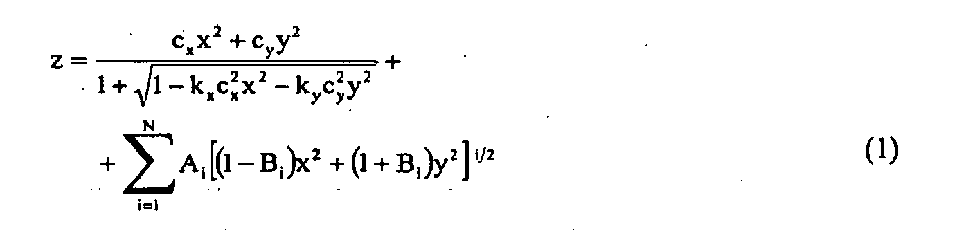
- This relation (1) differs from the relation (2) that is known in the technical literature due to the fact that it takes into account not only the fourth, sixth, eighth and tenth order of asphericity, but also all the others, without limiting in any way the maximum order of asphericity, and also considers all the odd terms; in this manner it is possible to obtain a better correction of the optical aberrations of the mirror.
- relation (1) is continuous and can be derived at least up to the partial first derivatives.
- a ij are the coefficients of the polynomial function.
- the polynomial relation (4) is continuous and derivable, since the indices i, j are positive integers; accordingly, ray tracing can be performed without particular difficulties.
- the parameters that define the relation of the external surface 5 are generally different from the ones that define the internal surface 6 and the maximum order of asphericity N can also be different in relation (1) or the maximum order N p and Mp in relation (4) in the directions x and y.
- the order N of each surface depends on the technical requirements and is not established beforehand but after numerical simulations.
- a further alternative for forming the surfaces 5 and 6 consists in describing the surfaces 5 and 6 with relations that are equivalent to relation (1) or relation (4), which interpolate them with sufficient precision over all the necessary extension.
- the reflecting device 1, and in particular the monolithic body 4 can be provided by means of a production method, according to a block diagram generally designated by the reference numeral X, which comprises substantially the following steps:
- the value in the coefficients A i and B i that have not yet been used must be set initially equal to zero or, if shifting to the configuration with two optical surfaces, the coefficients of the internal surface 6 are set initially equal to those of the external surface 5 and the value of the minimum thickness of the mirror, equal to the distance between the points O 1 and O 2 shown in Figure 1 , is established.
- the minimum thickness of the monolithic body 4 depends on the minimum requirements set by the statutory provisions in force, on the mechanical characteristics of the material used, on the steps of the production process (molding by pressure injection-compression or casting for thermosetting materials) and on the dimensions (width, height) of the monolithic body 4 itself or, if one decides to change the equation of the surfaces, all the coefficients of the new equation/equations must be calculated in such a manner that the surfaces, on the basis of the new equations, remain as unchanged as possible with respect to before.
- the convenience of changing the equation of the surfaces arises from the fact that as a function of the specifications of the mirror one formulation can be more efficient from the numeric standpoint than another one.
- step XI allows to calculate the value of the curvature c x of the external surface 5 that is needed to view the required horizontal object field.
- the curvature c y is equal to c x
- the taper coefficients k x and k y are equal to one
- the order of asphericity N is nil; in other words, the anamorphic aspherical surface degenerates into a spherical surface.
- the larger dimension is the horizontal one, as shown in Figure 1 , and the portion of mirror that is used most frequently is the central region 5a, because the upper region 15b views very distant cars, while the lower one 5c frames the road and is used only during maneuvering.
- the axis of revolution is centered with respect to the central portion 5a that is considered, i.e., the off-center y 0 and the angle of rotation ⁇ are nil.
- the method that will be described allows to calculate the optimum value of the curvature c y that reduces the anamorphosis of the image.
- a further reduction in anamorphosis is achieved during optimization of the surfaces, calibrating the coefficients k y and B i with respect to the coefficients k x and A i .
- the curvature c y can remain constant together with the value of the curvature c x .
- the curvature c x can vary independently of c y by sacrificing the correction of anamorphosis to the achievement of other more important targets, such as for example the field in a vertical direction.
- the subsequent step of optimization of the coefficients of the surface/ surfaces of the mirror i.e., of the coefficients k x , k y , A i and B i , allows to reduce distortion considerably, especially in the central region already mentioned, but the differentiation between the two curvatures ensures in any case a better correction of the image, even if the final distortion is extremely small.
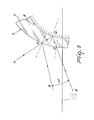
- Figure 3 illustrates the tracing of a ray that is reflected on the outer surface 5 and passes through the center of the eye of the driver.
- the values z', s and X ogg are known on the basis of the technical specifications of the mirror, and assuming a first-try value of the radius R x , by means of relations (5), (6), (7) and (9) it is possible to verify whether the assumed value of the radius allows to view the required object field. If it does not, this value is modified until the correct value is determined. In this step, the incidence height h must be set equal to the width of the mirror.
- relations (15) and (16) hereinafter it is possible to calculate the ratios between the horizontal and vertical dimensions of the object and of the image, which must be identical if the image must not be anamorphic (relations (17) and (18)). In particular, it is possible to obtain from relation (18) the magnification of the mirror in the vertical direction.
- the local reference triad X L1 , Y L1 and Z L must be positioned with respect to the reference triad of the vehicle X, Y and Z, providing step XII.
- Each rear-view mirror is provided with an adjustment system, which is manual or operated electrically with two degrees of freedom, and consists of two angle adjustments, by means of which it is possible to modify its orientation so that every driver, regardless of his height and ergonomic habits, can view or frame correctly the field required by the directive currently in force.
- an adjustment system which is manual or operated electrically with two degrees of freedom, and consists of two angle adjustments, by means of which it is possible to modify its orientation so that every driver, regardless of his height and ergonomic habits, can view or frame correctly the field required by the directive currently in force.
- the two adjustment angles ⁇ and ⁇ shown in Figure 2 which can be defined both by a sequence of rotations about the axes of the triad that is coupled to the vehicle and by a sequence of rotations with respect to triads which are successively rotated with respect to each other, are determined uniquely on the basis of the field to be viewed or framed and of the three-dimensional position of the driver and of the mirror.
- each anamorphic aspherical surface described by relation (2) is a function of 4+2N parameters.
- each surface is a function of N P +1 by M P +1 parameters.
- a total of fifty-three variables is required, of which twenty-five for the external surface 5, twenty-five for the internal surface 6, two off-centers and the rotation of the local reference system X i , Y i and Z i or X e , Y e and Z e with respect to the absolute triad X o , Y o and Z o that is coupled to the frame 2 of the reflecting device 1.
- Np + Mp 4 the maximum-order term is A 44 x 4 y 4 , but all the homogeneous terms such as A 80 x 8 , A 71 x 7 y, et cetera, are missing.
- N max max N p M p and limit accordingly the sum of the relation (4), including only the terms whose order is smaller than or equal to N.
- a fourth-order polynomial surface is defined by fifteen parameters and the monolithic body 4 is defined accordingly by thirty-three variables.
- the optimization step is based on the following cycle of operations:
- the error function is defined by the weighted sum of the deviations between the current value A i of a parameter such as for example the distortion and the desired value T i .
- W i is the weight of the i-th deviation
- N F is the total number of deviations.
- step 14 is performed.
- the function of the weights is dual: they allow to balance numerically the extent of the deviations between the current value of the generic parameter and the expected value, to avoid a numerically small deviation from becoming negligible within the error function. Furthermore, it is convenient to be able to direct the optimization process toward a solution that privileges the reduction of deviations of the more important parameters, giving them a greater weight than the less significant parameters.
- Relation (34) can for example be checked by entering it in the upper limits.
- the optimization step 15 begins and consists in defining a new set of values of the independent variables, ensuring a reduction of the error function and a possible better compliance with the set limits.
- the definition of the new value of the independent variables occurs by means of an iterative process, which is based on the logical specifications that have been implemented in the selected software, which for example, as already mentioned, can be provided by means of Matlab.
- step 16 for obtaining the monolithic body 4 made of transparent plastic material by pressure injection-compression or gravity casting.
- the reflecting surface 5 or 6 is obtained by means of a step 17 of deposition of a thin film of reflective metal, typically aluminum, chromium, titanium or silver according to the requirements, by deposition in high vacuum by vaporization and/or sputtering.
- a thin film of reflective metal typically aluminum, chromium, titanium or silver according to the requirements
- the reflecting device according to the invention fully achieves the intended aim and objects, city since it has a wide viewing angle which is larger than that of devices without blind spots, facilitating maneuvers when stationary.
- Another advantage of the reflecting device according to the invention consists in that it forms a single reflected image without significant deformations thereof, in compliance with the statutory provisions in force, ensuring better optical performance and contributing, from a production standpoint, to optimizing production costs by means of a reduction in thickness, maintaining it, for the entire length and width of the mirror, within a very small thickness variation range.
- a further advantage of the reflecting device according to the invention consists in that it forms a single reflected image without significant optical deformations thereof, in compliance with the type-approval rules in force.
- the general configuration i.e., the one in which the internal surface 6 is reflective and the external one 5 is refractive, is instead more advantageous, because it is possible to utilize the refractive index of the material of which the mirror is made and it is possible to optimize the shape of the internal surface 6 in order to obtain a better optical performance.
- the materials used may be any according to requirements and to the state of the art.
Landscapes
- Engineering & Computer Science (AREA)
- Multimedia (AREA)
- Mechanical Engineering (AREA)
- Optical Elements Other Than Lenses (AREA)
- Lenses (AREA)
- Rear-View Mirror Devices That Are Mounted On The Exterior Of The Vehicle (AREA)
Claims (13)
- Eine Reflektiervorrichtung mit weitem Betrachtungswinkel, geringer Verzerrung und Anamorphose und verringerter Dopplung reflektierter Bilder, insbesondere für Fahrzeuge, die einen monolithischen Körper (4) aus transparentem Kunststoffmaterial hat und eine äußere Oberfläche (5) und eine innere Oberfläche (6) umfasst, wobei die äußere Oberfläche (5) den zu erfassenden Objekten zugewandt und gegenüber der inneren Oberfläche (6) angeordnet ist, wobei die äußere Oberfläche (5) von einer anamorphotischen Oberfläche gebildet wird, die eine umdrehungsfreie Oberfläche ist, und die innere Oberfläche (6) und die äußere Oberfläche (5) die optische Achse (ZL) gemeinsam haben und durch mathematische Beziehungen bestimmt werden, die sich jeweils auf lokale Referenzsysteme (O1, XL1, YL1, ZL und O2, XL2, YL2, ZL) beziehen, welche eine kombinierte Dreh- und Translationsbewegung mit Bezug auf das Referenzsystem des Fahrzeugs (XO, YO) durchführen, auf dem die Reflektiervorrichtung (1) installiert ist, dadurch gekennzeichnet, dass:zumindest die äußere Oberfläche (5) vom anamorphotischen asphärischen Typ ist und durch folgende Beziehung bestimmt wird:
worin:- x, y, z die kartesischen Koordinaten sind, die die Position des generellen Punktes der Oberfläche im Verhältnis zum Scheitelpunkt bestimmen;- cx, cy die Krümmungen entsprechend der Generatrix in der Richtung x und y sind;- kx, ky die Konizitäts-Koeffizienten in den Richtungen x und y sind;- N die maximale Ordnung asphärischer Form ist;- Ai die asphärischen Koeffizienten, bezogen auf die i-te Ordnung, sind;- Bi für die Formkoeffizienten steht, mit denen es möglich ist, die i-te Ordnung in einer Richtung stärker asphärisch zu machen als in der anderen; im Speziellen ist, wenn Bi = 1, der Beitrag der Richtung x gleich null; wenn Bi = -1, ist der Beitrag der Richtung y gleich null; oderdie äußere Oberfläche (5) vom polynomischen Typ ist und durch folgende Beziehung definiert wird:
worin:- x, y, z die kartesischen Koordinaten sind, die die Position des generellen Punktes der Oberfläche im Verhältnis zum Scheitelpunkt bestimmen;- NP und MP für die maximale Ordnung der polynomischen Funktion in die Richtung x beziehungsweise y stehen;Aij die Koeffizienten der polynomischen Funktion sind. - Die Vorrichtung gemäß Anspruch 1, dadurch gekennzeichnet, dass die innere Oberfläche (6) von einer anamorphotischen Oberfläche gebildet wird, die eine umdrehungsfreie Oberfläche ist.
- Die Vorrichtung gemäß Anspruch 1, dadurch gekennzeichnet, dass die innere Oberfläche (6) vom anamorphotischen asphärischen Typ ist und durch folgende Beziehung definiert wird:

worin:- x, y, z die kartesischen Koordinaten sind, die die Position des allgemeinen Punktes der Oberfläche im Verhältnis zum Scheitelpunkt definieren;- cx, cy die Krümmungsradien entsprechend der Generatrix in der Richtung x und y sind;- kx, ky die Konizitäts-Koeffizienten in den Richtungen x und y sind;- N die maximale Ordnung asphärischer Form ist;- Ai die asphärischen Koeffizienten, bezogen auf die i-te Ordnung, sind;- Bi für die Formkoeffizienten steht, mit denen es möglich ist, die i-te Ordnung in einer Richtung stärker asphärisch zu machen als in der anderen; im Speziellen ist, wenn Bi = 1, der Beitrag der Richtung x gleich null; wenn Bi = -1, ist der Beitrag der Richtung y gleich null. - Die Vorrichtung gemäß Anspruch 1, dadurch gekennzeichnet, dass die innere Oberfläche (6) vom polynomischen Typ ist und durch folgende Beziehung definiert wird:

worin:- x, y, z die kartesischen Koordinaten sind, die die Position des generellen Punktes der Oberfläche im Verhältnis zum Scheitelpunkt bestimmen;- NP und MP für die maximale Ordnung der polynomischen Funktion in die Richtung x beziehungsweise y stehen;
Aij die Koeffizienten der polynomischen Funktion sind. - Die Vorrichtung gemäß einem oder mehreren der obigen Ansprüche, dadurch gekennzeichnet, dass die innere Oberfläche (6) und die äußere Oberfläche (5) vom Reflexionsbeziehungsweise vom Brechungstyp sind.
- Die Vorrichtung gemäß einem oder mehreren der Ansprüche 1 bis 4, dadurch gekennzeichnet, dass die äußere Oberfläche (5) vom Reflexionstyp ist.
- Die Vorrichtung gemäß einem oder mehreren der obigen Ansprüche, dadurch gekennzeichnet, dass der monolithische Körper (4) aus thermoplastischem Material mit hoher Lichtdurchlässigkeit besteht.
- Die Vorrichtung gemäß einem oder mehreren der Ansprüche 1 bis 6, dadurch gekennzeichnet, dass der monolithische Körper (4) aus wärmehärtbaren Materialien besteht.
- Die Vorrichtung gemäß Anspruch 7 oder 8, dadurch gekennzeichnet, dass sie einen dünne Schicht von reflektierendem Metall umfasst, die durch Hochvakuum-Ablagerung mit Hilfe von Verdampfung und/oder Vakuumzerstäuben auf die innere Oberfläche (6) oder die äußere Oberfläche (5) aufgetragen wird.
- Ein Verfahren zur Bereitstellung einer reflektierenden Vorrichtung mit weitem Betrachtungswinkel (geringer Verzerrung und Anamorphose und verringerter Dopplung reflektierter Bilder), insbesondere für Fahrzeuge, das Folgendes umfasst:mindestens einen Schritt (XI) zur Bestimmung der Art mathematischer Beziehungen, die die Form der Oberflächen eines monolithischen Körpers (4) bestimmen, welcher die reflektierende Vorrichtung (1) bildet, und eine innere Oberfläche (6) und eine äußere Oberfläche (5) umfassend,einen Schritt (XII) zur Positionierung der lokalen Referenzsysteme (Xi, Yi, Zi und Xe, Ye, Ze) der inneren Oberfläche (6) beziehungsweise der äußeren Oberfläche (5) im Raum mit Bezug auf das Referenzsystem des Fahrzeugs (Xo, Yo), auf dem die reflektierende Vorrichtung (1) installiert ist, in Abhängigkeit von ergonomischen und konstruktionsbedingten Beschränkungen des Fahrzeugs, wobei die innere Oberfläche (6) und die äußere Oberfläche (5) die optische Achse gemeinsam haben,einen Schritt (XIII) zur Messung und Berechnung des Bildfelds der reflektierenden Vorrichtung (1) in Abhängigkeit von der Ergonomie und Form des Fahrzeugs durch Verfolgung des optischen Strahlengangs, ausgehend vom Blickpunkt des Fahrers und von den optischen Eigenschaften der reflektierenden Vorrichtung (1), wobei der Messungs- und Berechnungsschritt (XIII) nach dem Positionierschritt (XII) durchgeführt wird, undeinen Schritt (XIV) zur Berechnung der Fehlerfunktion der optischen Eigenschaften mit Bezug auf Referenzwerte, wobei der Berechnungsschritt (XIV) nach dem Messungs- und Berechnungsschritt (XIII) durchgeführt wird.
- Das Verfahren gemäß Anspruch 10, das weiter einen Schritt (XV) zur Korrektur der Werte des ersten Versuchs in Abhängigkeit vom berechneten Fehler mit Bezug auf die Referenzwerte umfasst, wobei der Korrekturschritt (XV) nach dem Berechnungsschritt (XIV) und vor dem Bestimmungsschritt (XI) durchgeführt wird.
- Das Verfahren gemäß Anspruch 11, das weiter einen Schritt (XVI) zur Gewinnung des monolithischen Körpers (4) umfasst, der durch Formen durch Druckeinspritzung-Kompression oder Kokillenguss aus transparentem Kunststoffmaterial hergestellt wird, wobei der Gewinnungsschritt (XVI) nach dem Berechnungsschritt (XIV) durchgeführt wird.
- Das Verfahren gemäß Anspruch 12, das weiter einen Schritt (XVII) zur Ablagerung einer dünnen Schicht von reflektierendem Metall auf die innere Oberfläche (6) oder auf die äußere Oberfläche (5) durch Hochvakuum-Ablagerung mit Hilfe von Verdampfung und/oder Vakuumzerstäuben umfasst, wobei der Ablagerungsschritt (XVII) nach dem Gewinnungsschritt (XVI) durchgeführt wird.
Priority Applications (1)
| Application Number | Priority Date | Filing Date | Title |
|---|---|---|---|
| PL09759944T PL2367708T3 (pl) | 2008-12-02 | 2009-11-24 | Urządzenie odbijające o szerokim kącie widzenia, zmniejszonych zniekształceniach i anamorfozie oraz o zmniejszonym podwojeniu odbitych obrazów, przeznaczone w szczególności dla pojazdów |
Applications Claiming Priority (2)
| Application Number | Priority Date | Filing Date | Title |
|---|---|---|---|
| IT002132A ITMI20082132A1 (it) | 2008-12-02 | 2008-12-02 | Dispositivo riflettente ad ampio angolo di visuale, ridotta distorsione e anamorfosi e ridotto sdoppiamento delle immagini riflesse, particolarmente per veicoli. |
| PCT/EP2009/065776 WO2010063620A1 (en) | 2008-12-02 | 2009-11-24 | Reflecting device with wide vision angle, reduced distortion and anamorphosis and reduced doubling of reflected images, particularly for vehicles |
Publications (2)
| Publication Number | Publication Date |
|---|---|
| EP2367708A1 EP2367708A1 (de) | 2011-09-28 |
| EP2367708B1 true EP2367708B1 (de) | 2014-07-30 |
Family
ID=41280451
Family Applications (1)
| Application Number | Title | Priority Date | Filing Date |
|---|---|---|---|
| EP09759944.3A Active EP2367708B1 (de) | 2008-12-02 | 2009-11-24 | REFLEXIONSVORRICHTUNG MIT WEITEM SICHTWINKEL,REDUZIERTER VERZERRUNG UND& xA;ANAMORPHOSE UND REDUZIERTER VERDOPPLUNG REFLEKTIERTER BILDER,INSBESONDERE& xA;FÜR FAHRZEUGE |
Country Status (5)
| Country | Link |
|---|---|
| US (1) | US20110228414A1 (de) |
| EP (1) | EP2367708B1 (de) |
| IT (1) | ITMI20082132A1 (de) |
| PL (1) | PL2367708T3 (de) |
| WO (1) | WO2010063620A1 (de) |
Families Citing this family (4)
| Publication number | Priority date | Publication date | Assignee | Title |
|---|---|---|---|---|
| AU2012211407B2 (en) * | 2011-08-10 | 2014-12-11 | Smr Patents S.A.R.L. | Vehicular mirror with blind spot indicator |
| US20150274077A1 (en) * | 2014-04-01 | 2015-10-01 | Caterpillar Global Mining Llc | Convex mirror for large vehicles |
| KR102534392B1 (ko) | 2014-12-22 | 2023-05-19 | 피렐리 타이어 소시에떼 퍼 아찌오니 | 생산라인에서 타이어를 제어하기 위한 기기 |
| RU2696343C2 (ru) * | 2014-12-22 | 2019-08-01 | Пирелли Тайр С.П.А. | Способ и устройство для контроля шин на производственной линии |
Family Cites Families (10)
| Publication number | Priority date | Publication date | Assignee | Title |
|---|---|---|---|---|
| US5005962A (en) * | 1989-08-10 | 1991-04-09 | Edelman Karl W | Rearview mirror |
| DE9210425U1 (de) * | 1992-08-04 | 1993-04-01 | Hashemzadeh, Aliveza, 6200 Wiesbaden | Spezialspiegel |
| IT1307365B1 (it) * | 1999-03-25 | 2001-11-06 | Giovanni Manfre | Specchio retrovisore ad angolo di visuale ampio e ridotta distorsioned'immagine,per veicoli. |
| DE10002700A1 (de) * | 2000-01-22 | 2001-07-26 | Reitter & Schefenacker Gmbh | Außenrückblickspiegel |
| DE20002386U1 (de) * | 2000-02-10 | 2000-03-30 | Reitter & Schefenacker GmbH & Co. KG, 73730 Esslingen | Außenrückblickspiegel |
| DE20015125U1 (de) * | 2000-08-31 | 2000-12-07 | Reitter & Schefenacker GmbH & Co. KG, 73730 Esslingen | Außenrückblickspiegel für Fahrzeuge, vorzugsweise für Kraftfahrzeuge |
| JP3103016U (ja) * | 2004-01-26 | 2004-07-22 | 文夫 和田 | 部分曲面状車載バックミラー |
| US7517100B2 (en) * | 2006-11-01 | 2009-04-14 | Rosco Inc. | Asymmetric multiple constant RADII of curvature convex mirrors |
| DE102007010824A1 (de) * | 2007-03-06 | 2008-09-11 | Theodor Beck | Gleitsichtspiegel |
| TWM328040U (en) * | 2007-07-13 | 2008-03-01 | Sunlit Prec Technology Co Ltd | Improved casing structure of a card-shaped electronic product |
-
2008
- 2008-12-02 IT IT002132A patent/ITMI20082132A1/it unknown
-
2009
- 2009-11-24 WO PCT/EP2009/065776 patent/WO2010063620A1/en not_active Ceased
- 2009-11-24 PL PL09759944T patent/PL2367708T3/pl unknown
- 2009-11-24 US US13/131,841 patent/US20110228414A1/en not_active Abandoned
- 2009-11-24 EP EP09759944.3A patent/EP2367708B1/de active Active
Also Published As
| Publication number | Publication date |
|---|---|
| PL2367708T3 (pl) | 2015-01-30 |
| WO2010063620A1 (en) | 2010-06-10 |
| EP2367708A1 (de) | 2011-09-28 |
| US20110228414A1 (en) | 2011-09-22 |
| ITMI20082132A1 (it) | 2010-06-03 |
Similar Documents
| Publication | Publication Date | Title |
|---|---|---|
| JP4025368B2 (ja) | 眼鏡用の偏心非矯正レンズ | |
| EP1385038B1 (de) | Brillenlinsenentwurfsverfahren und brillenlinse | |
| US10061126B2 (en) | Optical device | |
| EP1029254B1 (de) | Verbesserte ophthalmische linse | |
| US4613217A (en) | Spectacle lens having astigmatic power | |
| US8817356B2 (en) | Vehicular rearview mirror with increased field-of-view | |
| US8100529B2 (en) | Progressive-addition lens | |
| JP2007264666A (ja) | 眼鏡用の偏心非矯正レンズ | |
| US5980050A (en) | Vehicle mirrors having convex curvatures and methods of making same | |
| KR101572132B1 (ko) | 시도 조절이 가능한 전방 상향 시현용 광학계 | |
| CN108027524B (zh) | 用于产生虚拟图像的成像光学系统的眼镜镜片以及用于生产此类眼镜镜片的方法 | |
| JPH03209210A (ja) | ヘッドアップデイスプレイ、楔形フロントガラス及び楔形フロントガラスの組立方法 | |
| CN106526852B (zh) | 目镜光学系统 | |
| US6832834B2 (en) | Method for computing a progressive spectacle lens and methods for manufacturing a spectacle lens of this kind | |
| JP2019034708A (ja) | 普通のフロントガラスを使用したディスプレイ装置、および、その自動車のヘッドアップディスプレイシステム | |
| GB2458898A (en) | A head up display system with ghost image elimination means | |
| US20110228414A1 (en) | Reflecting device with wide vision angle, reduced distortion and anamorphosis and reduced doubling of reflected images, particularly for vehicles | |
| Kim et al. | Optical system design for a head-up display using aberration analysis of an off-axis two-mirror system | |
| JP6226873B2 (ja) | 眼用累進レンズ及び半仕上げレンズブランクの組を決定する方法 | |
| CN109073913B (zh) | 用于加工未成品光学镜片构件的方法 | |
| US20060098161A1 (en) | Non-corrective lenses with improved peripheral vision | |
| US20240160018A1 (en) | Wavefront manipulator for a head-up display, optical arrangement, and head-up display | |
| KR101604087B1 (ko) | 전방 상향 시현용 광학계 | |
| JP4971180B2 (ja) | 形成画像を歪ませることなしに盲点の極小化を実現する間接観察システム | |
| US11914120B2 (en) | Windshield corrective optic for forward facing cameras |
Legal Events
| Date | Code | Title | Description |
|---|---|---|---|
| PUAI | Public reference made under article 153(3) epc to a published international application that has entered the european phase |
Free format text: ORIGINAL CODE: 0009012 |
|
| 17P | Request for examination filed |
Effective date: 20110624 |
|
| AK | Designated contracting states |
Kind code of ref document: A1 Designated state(s): AT BE BG CH CY CZ DE DK EE ES FI FR GB GR HR HU IE IS IT LI LT LU LV MC MK MT NL NO PL PT RO SE SI SK SM TR |
|
| DAX | Request for extension of the european patent (deleted) | ||
| GRAP | Despatch of communication of intention to grant a patent |
Free format text: ORIGINAL CODE: EPIDOSNIGR1 |
|
| INTG | Intention to grant announced |
Effective date: 20130912 |
|
| GRAS | Grant fee paid |
Free format text: ORIGINAL CODE: EPIDOSNIGR3 |
|
| GRAA | (expected) grant |
Free format text: ORIGINAL CODE: 0009210 |
|
| AK | Designated contracting states |
Kind code of ref document: B1 Designated state(s): AT BE BG CH CY CZ DE DK EE ES FI FR GB GR HR HU IE IS IT LI LT LU LV MC MK MT NL NO PL PT RO SE SI SK SM TR |
|
| REG | Reference to a national code |
Ref country code: GB Ref legal event code: FG4D |
|
| REG | Reference to a national code |
Ref country code: CH Ref legal event code: EP |
|
| REG | Reference to a national code |
Ref country code: AT Ref legal event code: REF Ref document number: 679793 Country of ref document: AT Kind code of ref document: T Effective date: 20140815 |
|
| REG | Reference to a national code |
Ref country code: IE Ref legal event code: FG4D |
|
| REG | Reference to a national code |
Ref country code: DE Ref legal event code: R096 Ref document number: 602009025680 Country of ref document: DE Effective date: 20140911 |
|
| REG | Reference to a national code |
Ref country code: AT Ref legal event code: MK05 Ref document number: 679793 Country of ref document: AT Kind code of ref document: T Effective date: 20140730 |
|
| REG | Reference to a national code |
Ref country code: NL Ref legal event code: VDEP Effective date: 20140730 |
|
| REG | Reference to a national code |
Ref country code: LT Ref legal event code: MG4D |
|
| PG25 | Lapsed in a contracting state [announced via postgrant information from national office to epo] |
Ref country code: PT Free format text: LAPSE BECAUSE OF FAILURE TO SUBMIT A TRANSLATION OF THE DESCRIPTION OR TO PAY THE FEE WITHIN THE PRESCRIBED TIME-LIMIT Effective date: 20141202 Ref country code: LT Free format text: LAPSE BECAUSE OF FAILURE TO SUBMIT A TRANSLATION OF THE DESCRIPTION OR TO PAY THE FEE WITHIN THE PRESCRIBED TIME-LIMIT Effective date: 20140730 Ref country code: BG Free format text: LAPSE BECAUSE OF FAILURE TO SUBMIT A TRANSLATION OF THE DESCRIPTION OR TO PAY THE FEE WITHIN THE PRESCRIBED TIME-LIMIT Effective date: 20141030 Ref country code: GR Free format text: LAPSE BECAUSE OF FAILURE TO SUBMIT A TRANSLATION OF THE DESCRIPTION OR TO PAY THE FEE WITHIN THE PRESCRIBED TIME-LIMIT Effective date: 20141031 Ref country code: FI Free format text: LAPSE BECAUSE OF FAILURE TO SUBMIT A TRANSLATION OF THE DESCRIPTION OR TO PAY THE FEE WITHIN THE PRESCRIBED TIME-LIMIT Effective date: 20140730 Ref country code: ES Free format text: LAPSE BECAUSE OF FAILURE TO SUBMIT A TRANSLATION OF THE DESCRIPTION OR TO PAY THE FEE WITHIN THE PRESCRIBED TIME-LIMIT Effective date: 20140730 Ref country code: NO Free format text: LAPSE BECAUSE OF FAILURE TO SUBMIT A TRANSLATION OF THE DESCRIPTION OR TO PAY THE FEE WITHIN THE PRESCRIBED TIME-LIMIT Effective date: 20141030 Ref country code: SE Free format text: LAPSE BECAUSE OF FAILURE TO SUBMIT A TRANSLATION OF THE DESCRIPTION OR TO PAY THE FEE WITHIN THE PRESCRIBED TIME-LIMIT Effective date: 20140730 |
|
| REG | Reference to a national code |
Ref country code: PL Ref legal event code: T3 |
|
| PG25 | Lapsed in a contracting state [announced via postgrant information from national office to epo] |
Ref country code: NL Free format text: LAPSE BECAUSE OF FAILURE TO SUBMIT A TRANSLATION OF THE DESCRIPTION OR TO PAY THE FEE WITHIN THE PRESCRIBED TIME-LIMIT Effective date: 20140730 Ref country code: IS Free format text: LAPSE BECAUSE OF FAILURE TO SUBMIT A TRANSLATION OF THE DESCRIPTION OR TO PAY THE FEE WITHIN THE PRESCRIBED TIME-LIMIT Effective date: 20141130 Ref country code: AT Free format text: LAPSE BECAUSE OF FAILURE TO SUBMIT A TRANSLATION OF THE DESCRIPTION OR TO PAY THE FEE WITHIN THE PRESCRIBED TIME-LIMIT Effective date: 20140730 Ref country code: CY Free format text: LAPSE BECAUSE OF FAILURE TO SUBMIT A TRANSLATION OF THE DESCRIPTION OR TO PAY THE FEE WITHIN THE PRESCRIBED TIME-LIMIT Effective date: 20140730 Ref country code: LV Free format text: LAPSE BECAUSE OF FAILURE TO SUBMIT A TRANSLATION OF THE DESCRIPTION OR TO PAY THE FEE WITHIN THE PRESCRIBED TIME-LIMIT Effective date: 20140730 Ref country code: HR Free format text: LAPSE BECAUSE OF FAILURE TO SUBMIT A TRANSLATION OF THE DESCRIPTION OR TO PAY THE FEE WITHIN THE PRESCRIBED TIME-LIMIT Effective date: 20140730 |
|
| PG25 | Lapsed in a contracting state [announced via postgrant information from national office to epo] |
Ref country code: RO Free format text: LAPSE BECAUSE OF FAILURE TO SUBMIT A TRANSLATION OF THE DESCRIPTION OR TO PAY THE FEE WITHIN THE PRESCRIBED TIME-LIMIT Effective date: 20140730 Ref country code: EE Free format text: LAPSE BECAUSE OF FAILURE TO SUBMIT A TRANSLATION OF THE DESCRIPTION OR TO PAY THE FEE WITHIN THE PRESCRIBED TIME-LIMIT Effective date: 20140730 Ref country code: DK Free format text: LAPSE BECAUSE OF FAILURE TO SUBMIT A TRANSLATION OF THE DESCRIPTION OR TO PAY THE FEE WITHIN THE PRESCRIBED TIME-LIMIT Effective date: 20140730 Ref country code: SK Free format text: LAPSE BECAUSE OF FAILURE TO SUBMIT A TRANSLATION OF THE DESCRIPTION OR TO PAY THE FEE WITHIN THE PRESCRIBED TIME-LIMIT Effective date: 20140730 |
|
| REG | Reference to a national code |
Ref country code: DE Ref legal event code: R097 Ref document number: 602009025680 Country of ref document: DE |
|
| REG | Reference to a national code |
Ref country code: FR Ref legal event code: PLFP Year of fee payment: 6 |
|
| PLBE | No opposition filed within time limit |
Free format text: ORIGINAL CODE: 0009261 |
|
| STAA | Information on the status of an ep patent application or granted ep patent |
Free format text: STATUS: NO OPPOSITION FILED WITHIN TIME LIMIT |
|
| PG25 | Lapsed in a contracting state [announced via postgrant information from national office to epo] |
Ref country code: BE Free format text: LAPSE BECAUSE OF NON-PAYMENT OF DUE FEES Effective date: 20141130 Ref country code: LU Free format text: LAPSE BECAUSE OF FAILURE TO SUBMIT A TRANSLATION OF THE DESCRIPTION OR TO PAY THE FEE WITHIN THE PRESCRIBED TIME-LIMIT Effective date: 20141124 Ref country code: MC Free format text: LAPSE BECAUSE OF FAILURE TO SUBMIT A TRANSLATION OF THE DESCRIPTION OR TO PAY THE FEE WITHIN THE PRESCRIBED TIME-LIMIT Effective date: 20140730 |
|
| REG | Reference to a national code |
Ref country code: CH Ref legal event code: PL |
|
| 26N | No opposition filed |
Effective date: 20150504 |
|
| PG25 | Lapsed in a contracting state [announced via postgrant information from national office to epo] |
Ref country code: CH Free format text: LAPSE BECAUSE OF NON-PAYMENT OF DUE FEES Effective date: 20141130 Ref country code: LI Free format text: LAPSE BECAUSE OF NON-PAYMENT OF DUE FEES Effective date: 20141130 |
|
| REG | Reference to a national code |
Ref country code: IE Ref legal event code: MM4A |
|
| PG25 | Lapsed in a contracting state [announced via postgrant information from national office to epo] |
Ref country code: IE Free format text: LAPSE BECAUSE OF NON-PAYMENT OF DUE FEES Effective date: 20141124 |
|
| PG25 | Lapsed in a contracting state [announced via postgrant information from national office to epo] |
Ref country code: SI Free format text: LAPSE BECAUSE OF FAILURE TO SUBMIT A TRANSLATION OF THE DESCRIPTION OR TO PAY THE FEE WITHIN THE PRESCRIBED TIME-LIMIT Effective date: 20140730 |
|
| PG25 | Lapsed in a contracting state [announced via postgrant information from national office to epo] |
Ref country code: SM Free format text: LAPSE BECAUSE OF FAILURE TO SUBMIT A TRANSLATION OF THE DESCRIPTION OR TO PAY THE FEE WITHIN THE PRESCRIBED TIME-LIMIT Effective date: 20140730 |
|
| REG | Reference to a national code |
Ref country code: FR Ref legal event code: PLFP Year of fee payment: 7 |
|
| PG25 | Lapsed in a contracting state [announced via postgrant information from national office to epo] |
Ref country code: BE Free format text: LAPSE BECAUSE OF FAILURE TO SUBMIT A TRANSLATION OF THE DESCRIPTION OR TO PAY THE FEE WITHIN THE PRESCRIBED TIME-LIMIT Effective date: 20140730 Ref country code: TR Free format text: LAPSE BECAUSE OF FAILURE TO SUBMIT A TRANSLATION OF THE DESCRIPTION OR TO PAY THE FEE WITHIN THE PRESCRIBED TIME-LIMIT Effective date: 20140730 Ref country code: HU Free format text: LAPSE BECAUSE OF FAILURE TO SUBMIT A TRANSLATION OF THE DESCRIPTION OR TO PAY THE FEE WITHIN THE PRESCRIBED TIME-LIMIT; INVALID AB INITIO Effective date: 20091124 Ref country code: MT Free format text: LAPSE BECAUSE OF FAILURE TO SUBMIT A TRANSLATION OF THE DESCRIPTION OR TO PAY THE FEE WITHIN THE PRESCRIBED TIME-LIMIT Effective date: 20140730 |
|
| REG | Reference to a national code |
Ref country code: FR Ref legal event code: ST Effective date: 20160729 |
|
| REG | Reference to a national code |
Ref country code: FR Ref legal event code: RN Effective date: 20160817 |
|
| REG | Reference to a national code |
Ref country code: FR Ref legal event code: FC Effective date: 20160927 |
|
| PG25 | Lapsed in a contracting state [announced via postgrant information from national office to epo] |
Ref country code: FR Free format text: LAPSE BECAUSE OF NON-PAYMENT OF DUE FEES Effective date: 20151130 |
|
| PGRI | Patent reinstated in contracting state [announced from national office to epo] |
Ref country code: FR Effective date: 20160927 |
|
| REG | Reference to a national code |
Ref country code: FR Ref legal event code: PLFP Year of fee payment: 8 |
|
| REG | Reference to a national code |
Ref country code: FR Ref legal event code: PLFP Year of fee payment: 9 |
|
| PG25 | Lapsed in a contracting state [announced via postgrant information from national office to epo] |
Ref country code: MK Free format text: LAPSE BECAUSE OF FAILURE TO SUBMIT A TRANSLATION OF THE DESCRIPTION OR TO PAY THE FEE WITHIN THE PRESCRIBED TIME-LIMIT Effective date: 20140730 |
|
| REG | Reference to a national code |
Ref country code: DE Ref legal event code: R082 Ref document number: 602009025680 Country of ref document: DE Representative=s name: SCHIEBER - FARAGO PATENTANWAELTE, DE Ref country code: DE Ref legal event code: R082 Ref document number: 602009025680 Country of ref document: DE Representative=s name: FARAGO PATENTANWALTSGESELLSCHAFT MBH, DE |
|
| REG | Reference to a national code |
Ref country code: DE Ref legal event code: R082 Ref document number: 602009025680 Country of ref document: DE Representative=s name: SCHIEBER - FARAGO PATENTANWAELTE, DE |
|
| PGFP | Annual fee paid to national office [announced via postgrant information from national office to epo] |
Ref country code: FR Payment date: 20221118 Year of fee payment: 14 Ref country code: CZ Payment date: 20221116 Year of fee payment: 14 |
|
| P01 | Opt-out of the competence of the unified patent court (upc) registered |
Effective date: 20230528 |
|
| PGFP | Annual fee paid to national office [announced via postgrant information from national office to epo] |
Ref country code: DE Payment date: 20240321 Year of fee payment: 15 Ref country code: GB Payment date: 20240320 Year of fee payment: 15 |
|
| PGFP | Annual fee paid to national office [announced via postgrant information from national office to epo] |
Ref country code: PL Payment date: 20240313 Year of fee payment: 15 |
|
| PG25 | Lapsed in a contracting state [announced via postgrant information from national office to epo] |
Ref country code: CZ Free format text: LAPSE BECAUSE OF NON-PAYMENT OF DUE FEES Effective date: 20231124 |
|
| PG25 | Lapsed in a contracting state [announced via postgrant information from national office to epo] |
Ref country code: CZ Free format text: LAPSE BECAUSE OF NON-PAYMENT OF DUE FEES Effective date: 20231124 |
|
| PG25 | Lapsed in a contracting state [announced via postgrant information from national office to epo] |
Ref country code: FR Free format text: LAPSE BECAUSE OF NON-PAYMENT OF DUE FEES Effective date: 20231130 |
|
| PG25 | Lapsed in a contracting state [announced via postgrant information from national office to epo] |
Ref country code: FR Free format text: LAPSE BECAUSE OF NON-PAYMENT OF DUE FEES Effective date: 20231130 |
|
| REG | Reference to a national code |
Ref country code: DE Ref legal event code: R119 Ref document number: 602009025680 Country of ref document: DE |
|
| GBPC | Gb: european patent ceased through non-payment of renewal fee |
Effective date: 20241124 |
|
| PG25 | Lapsed in a contracting state [announced via postgrant information from national office to epo] |
Ref country code: DE Free format text: LAPSE BECAUSE OF NON-PAYMENT OF DUE FEES Effective date: 20250603 |
|
| PG25 | Lapsed in a contracting state [announced via postgrant information from national office to epo] |
Ref country code: GB Free format text: LAPSE BECAUSE OF NON-PAYMENT OF DUE FEES Effective date: 20241124 |
|
| PGFP | Annual fee paid to national office [announced via postgrant information from national office to epo] |
Ref country code: IT Payment date: 20251120 Year of fee payment: 17 |