EP2367294B1 - Drahtloses Kommunikationssystem mit einer höheren Modulationsbandbreite als die Bandbreite der Sender- und/oder Empfängerantennen - Google Patents
Drahtloses Kommunikationssystem mit einer höheren Modulationsbandbreite als die Bandbreite der Sender- und/oder Empfängerantennen Download PDFInfo
- Publication number
- EP2367294B1 EP2367294B1 EP10156029.0A EP10156029A EP2367294B1 EP 2367294 B1 EP2367294 B1 EP 2367294B1 EP 10156029 A EP10156029 A EP 10156029A EP 2367294 B1 EP2367294 B1 EP 2367294B1
- Authority
- EP
- European Patent Office
- Prior art keywords
- antenna
- bandwidth
- communication system
- frequency
- signal
- Prior art date
- Legal status (The legal status is an assumption and is not a legal conclusion. Google has not performed a legal analysis and makes no representation as to the accuracy of the status listed.)
- Active
Links
- 238000004891 communication Methods 0.000 title claims description 91
- 230000006870 function Effects 0.000 claims description 40
- 238000012546 transfer Methods 0.000 claims description 39
- 238000012545 processing Methods 0.000 claims description 31
- 238000000034 method Methods 0.000 claims description 29
- 230000001939 inductive effect Effects 0.000 claims description 19
- 230000005540 biological transmission Effects 0.000 claims description 14
- 230000017105 transposition Effects 0.000 claims description 11
- 239000003990 capacitor Substances 0.000 claims description 10
- 230000008878 coupling Effects 0.000 claims description 8
- 238000010168 coupling process Methods 0.000 claims description 8
- 238000005859 coupling reaction Methods 0.000 claims description 8
- 238000005259 measurement Methods 0.000 claims description 5
- 230000001131 transforming effect Effects 0.000 claims description 3
- 230000010363 phase shift Effects 0.000 claims description 2
- 230000004044 response Effects 0.000 description 11
- 230000001965 increasing effect Effects 0.000 description 9
- 230000005236 sound signal Effects 0.000 description 9
- 230000008901 benefit Effects 0.000 description 8
- 238000010586 diagram Methods 0.000 description 6
- 230000002829 reductive effect Effects 0.000 description 5
- 238000009966 trimming Methods 0.000 description 5
- 230000035945 sensitivity Effects 0.000 description 4
- 238000013519 translation Methods 0.000 description 4
- 238000004590 computer program Methods 0.000 description 3
- 230000000694 effects Effects 0.000 description 3
- 238000001914 filtration Methods 0.000 description 3
- 230000001413 cellular effect Effects 0.000 description 2
- 239000013256 coordination polymer Substances 0.000 description 2
- 230000001419 dependent effect Effects 0.000 description 2
- 230000005670 electromagnetic radiation Effects 0.000 description 2
- 230000006698 induction Effects 0.000 description 2
- 230000008569 process Effects 0.000 description 2
- 238000005070 sampling Methods 0.000 description 2
- 244000068988 Glycine max Species 0.000 description 1
- 230000004913 activation Effects 0.000 description 1
- 230000003466 anti-cipated effect Effects 0.000 description 1
- 230000002238 attenuated effect Effects 0.000 description 1
- 239000000969 carrier Substances 0.000 description 1
- 230000008859 change Effects 0.000 description 1
- 238000012937 correction Methods 0.000 description 1
- 230000003247 decreasing effect Effects 0.000 description 1
- 230000005674 electromagnetic induction Effects 0.000 description 1
- 230000005284 excitation Effects 0.000 description 1
- BTCSSZJGUNDROE-UHFFFAOYSA-N gamma-aminobutyric acid Chemical compound NCCCC(O)=O BTCSSZJGUNDROE-UHFFFAOYSA-N 0.000 description 1
- 238000011065 in-situ storage Methods 0.000 description 1
- 230000002452 interceptive effect Effects 0.000 description 1
- 230000000670 limiting effect Effects 0.000 description 1
- 238000012986 modification Methods 0.000 description 1
- 230000004048 modification Effects 0.000 description 1
- 230000003071 parasitic effect Effects 0.000 description 1
- 230000009467 reduction Effects 0.000 description 1
- 238000001228 spectrum Methods 0.000 description 1
- 230000009466 transformation Effects 0.000 description 1
- 229910000859 α-Fe Inorganic materials 0.000 description 1
Images


Classifications
-
- H—ELECTRICITY
- H04—ELECTRIC COMMUNICATION TECHNIQUE
- H04B—TRANSMISSION
- H04B5/00—Near-field transmission systems, e.g. inductive loop type
-
- H—ELECTRICITY
- H04—ELECTRIC COMMUNICATION TECHNIQUE
- H04R—LOUDSPEAKERS, MICROPHONES, GRAMOPHONE PICK-UPS OR LIKE ACOUSTIC ELECTROMECHANICAL TRANSDUCERS; DEAF-AID SETS; PUBLIC ADDRESS SYSTEMS
- H04R2225/00—Details of deaf aids covered by H04R25/00, not provided for in any of its subgroups
- H04R2225/51—Aspects of antennas or their circuitry in or for hearing aids
-
- H—ELECTRICITY
- H04—ELECTRIC COMMUNICATION TECHNIQUE
- H04R—LOUDSPEAKERS, MICROPHONES, GRAMOPHONE PICK-UPS OR LIKE ACOUSTIC ELECTROMECHANICAL TRANSDUCERS; DEAF-AID SETS; PUBLIC ADDRESS SYSTEMS
- H04R25/00—Deaf-aid sets, i.e. electro-acoustic or electro-mechanical hearing aids; Electric tinnitus maskers providing an auditory perception
- H04R25/55—Deaf-aid sets, i.e. electro-acoustic or electro-mechanical hearing aids; Electric tinnitus maskers providing an auditory perception using an external connection, either wireless or wired
- H04R25/554—Deaf-aid sets, i.e. electro-acoustic or electro-mechanical hearing aids; Electric tinnitus maskers providing an auditory perception using an external connection, either wireless or wired using a wireless connection, e.g. between microphone and amplifier or using Tcoils
-
- Y—GENERAL TAGGING OF NEW TECHNOLOGICAL DEVELOPMENTS; GENERAL TAGGING OF CROSS-SECTIONAL TECHNOLOGIES SPANNING OVER SEVERAL SECTIONS OF THE IPC; TECHNICAL SUBJECTS COVERED BY FORMER USPC CROSS-REFERENCE ART COLLECTIONS [XRACs] AND DIGESTS
- Y02—TECHNOLOGIES OR APPLICATIONS FOR MITIGATION OR ADAPTATION AGAINST CLIMATE CHANGE
- Y02D—CLIMATE CHANGE MITIGATION TECHNOLOGIES IN INFORMATION AND COMMUNICATION TECHNOLOGIES [ICT], I.E. INFORMATION AND COMMUNICATION TECHNOLOGIES AIMING AT THE REDUCTION OF THEIR OWN ENERGY USE
- Y02D30/00—Reducing energy consumption in communication networks
- Y02D30/70—Reducing energy consumption in communication networks in wireless communication networks
Definitions
- the present application relates to antennas for wireless communication systems, e.g. for such systems comprising portable devices, e.g. listening devices.
- the disclosure relates specifically to a wireless communication system.
- the application furthermore relates to a radio frequency receiver part and to a radio frequency transmitter part for use in a wireless communication system.
- the application moreover relates to the use of a narrowband antenna for transmitting or receiving a signal in a communication system and to a method of calibrating a narrowband antenna/tank frequency transfer function of a wireless communication system.
- the disclosure may e.g. be useful in applications involving devices such as handheld communication devices, e.g. listening devices involving wireless communication.
- antenna bandwidth ( BW ant ) is much larger than the bandwidth of the signal ( BW sig ) to be transmitted and received to make sure that all the signal power is received and not corrupted in any way.
- Some antennas become more efficient as their bandwidth is reduced. In particular that is true for resonated magnetic link antennas as the ones typically used in connection with hearing aids. However, if the antenna bandwidth is too narrow, the antenna frequency response will distort the communication signal. The trade off between antenna efficiency and signal distortion leads to a certain optimal antenna bandwidth of existing systems.
- EP 0 261 935 A2 discloses an electrically small antenna for receiving radio signals with large bandwidth.
- the document discloses a tradition in the use of electrically small antennas, namely the electronic widening of the antenna bandwidth.
- the inherent small bandwidth of the electrically small antenna is widened by a tuning circuit.
- the reason for the tradition is that it is difficult to handle the large phase and amplitude variations over frequency caused by antennas tuned to a narrow bandwidth.
- Prior art antennas are thus typically tuned to a bandwidth similar to or exceeding the bandwidth of the radio signals.
- the widening of the antenna bandwidth has a negative influence on the receiving efficiency and the noise level of the antenna.
- US 2008/158076 A1 describes a narrow band antenna for use in wide band systems.
- the effective bandwidth of a dynamically adjustable antenna with a narrow natural bandwidth delineated by a first frequency change can be moved from the natural bandwidth to another narrow bandwidth of interest within a wide band spectrum using a tuning circuit.
- US 6,424,820 deals with a short range inductively coupled wireless communication system employing analog frequency modulation of a high frequency carrier and magnetic coupling between a transmitting antenna and a receiving antenna.
- a transmitter coupled to the transmitting antenna modulates multiple high-fidelity analog audio signals and digital control messages onto separate high frequency (“HF") carriers.
- the receiving antenna is coupled to a demodulator which reproduces the audio frequency signals and decodes control messages sent by the transmitter.
- US 2002/0183013 A1 deals with a programmable radio frequency (RF) sub-system and wireless communications devices using such an integrated antenna/filter sub-system.
- the programmable RF front end subassembly includes two antennas, RF filter sections that are integral to each antenna, and a programmable logic device as an antenna control unit.
- Each antenna consists of a planar inverted "F" antenna (PIFA) that is tuned to operate over a range of frequencies using voltage variable capacitors or RF switches that connect various capacitive loads in order to achieve the desired resonant frequencies.
- PIFA planar inverted "F" antenna
- 'antenna bandwidth' (' BW ant ' ) is in the present context taken to mean the bandwidth of the antenna when connected to the communication system (not the bandwidth of the stand alone antenna).
- the term 'antenna' or 'narrow band antenna' is taken to mean the 'resonating system comprising the antenna and tuning or loading components' (e.g. the load capacitance of an LC resonating or tuning system comprising an exemplary (e.g. inductive) narrow band antenna, cf. e.g. FIG. 3 , including e.g. possible capacitance of the load system connected to terminals V out ).
- 'antenna/tank circuit' and 'antenna and tuning circuit' are used interchangeably and are not intended to have different meanings, unless specifically indicated.
- the terms cover the resonating system constituted by the antenna and other components electrically connected to the antenna and responsible for storing and emitting or receiving electromagnetic energy during transmission or reception of an electrical signal (cf. e.g. FIG. 3, 4 ).
- a wireless communication system :
- An object of the present application is to provide a wireless communication system having a relatively large signal bandwidth with an electrically small antenna. Another object is to provide a wireless communication system suitable for use in a portable (e.g. battery driven) device or system.
- the term 'low power device' is in the present context taken to mean a device whose energy budget is restricted, e.g. because it is a portable device, e.g. comprising an energy source (e.g. of limited size, e.g. with a maximum capacity of 1000 mAh, such as 500 mAh), which - without being exchanged or recharged - is of limited duration (the limited duration being e.g. of the order of hours or days, e.g. max. 1 or 3 or 7 or 10 days(during normal operation of the device), such duration being limited compared to the expected life time of the device).
- an energy source e.g. of limited size, e.g. with a maximum capacity of 1000 mAh, such as 500 mAh
- the limited duration being e.g. of the order of hours or days, e.g. max. 1 or 3 or 7 or 10 days(during normal operation of the device), such duration being limited compared to the expected life time of the device.
- the wireless communication system further comprises at least one equalization filter electrically connected to the Tx- or to the Rx-antennas, wherein the equalization filter(s) is/are adapted for compensating for the amplitude and/or phase distortion introduced by the narrowband Tx- and/or Rx-antennas.
- one equalization filter located in either of the transmitter or receiver parts is adapted to compensate for the amplitude and/or phase distortion introduced by the narrowband Tx- and/or Rx-antennas.
- the transmitter and receiver parts each comprise an equalization filter to compensate for amplitude and/or phase distortion introduced by their respective narrowband Tx- and Rx-antennas.
- the Tx-antenna frequency response is described by the transfer function H Tx (s) , s being the Laplace-parameter, and the equalization filter of the transmitter part is adapted to have a transfer function of 1/H Tx (s)
- the link budget i.e. transmission range and/or data rate
- the transmitter and receiver parts each further comprises a frequency transposition unit (e.g. a mixer) electrically connected to the Tx- and Rx-antennas of the transmitter and receiver parts, respectively, the frequency transposition units being adapted for transforming a frequency range of an input signal to another frequency range, and wherein the equalization filter(s) is/are adapted for compensating for the amplitude and/or phase distortion introduced by the Tx- and/or Rx-antennas in combination with said frequency transposition units.
- a frequency transposition unit e.g. a mixer
- the equalization filter(s) is/are implemented as first order filter(s) with a real zero located at about the same frequency as the real dominant pole of the combined antenna and frequency translating blocks. This has the advantage of providing a relatively simple implementation of the equalization filter. This solution is particularly advantageous in an embodiment wherein the narrowband antenna(s) can be approximately represented (e.g. is dominated) by a second order transfer function and a resonance frequency that is equal to a centre frequency of the transmitted (wireless) signal.
- the term ' at about the same frequency as the real dominant pole of the antenna block(s) or of the combined antenna and frequency translating blocks' is taken to mean that the difference in frequency is smaller than 20%, such as smaller than 10%, such as smaller than 5%.
- k is smaller than or equal to 0.5. In an embodiment, k is in the range from 0.1 to 0.75, such as in the range from 0.1 to 0.5, e.g. in the range from 0.2 to 0.4.
- the wireless link established by the transmitter and receiver parts can be of any type.
- the wireless link is used under power constraints in that at least one of the devices comprises a portable (typically battery driven) communication or listening device.
- the wireless link is a link based on near-field communication, e.g. an inductive link based on an inductive coupling between antenna coils of the transmitter and receiver parts of the first and second communication devices, respectively.
- the wireless link is based on far-field, electromagnetic radiation.
- the communication via the wireless link is arranged according to a specific modulation scheme, e.g.
- an analogue modulation scheme such as FM (frequency modulation) or AM (amplitude modulation)
- a digital modulation scheme such as ASK (amplitude shift keying), e.g. On-Off keying, FSK (frequency shift keying), PSK (phase shift keying) or QAM (quadrature amplitude modulation).
- ASK amplitude shift keying
- FSK frequency shift keying
- PSK phase shift keying
- QAM quadrature amplitude modulation
- the transmitter and receiver parts are adapted to implement a wireless link based on inductive coupling between the transmitting and receiving antennas.
- the Tx- and Rx-antennas comprise inductance coils, which when the first and second devices comprising the transmitter and receiver parts, respectively, are brought within an operating distance of each other have a mutual inductive coupling sufficient for transferring the electrical signal from the transmitter part to the receiver part.
- the system is adapted to provide that such operating distance is up to 0.1 m, such as up to 0.3 m, such as up to 0.5 m, such as larger than 1 m, e.g. up to 2 m or more.
- the system is adapted to provide that such operating distance is in the range from 0.3 m to 50 m, e.g. in the range from 0.3 m to 5 m, e.g. in the range from 0.3 m to 1.5 m.
- the operating distance depends among other parameters on the transmit power, transmit frequency/bit rate, signal bandwidth, etc.
- inductive communication Various aspects of inductive communication are e.g. discussed in EP 1 107 472 A2 , EP 1 777 644 A1 and US 2005/0110700 A1 .
- WO 2005/055654 and WO 2005/053179 describe various aspects of a hearing aid comprising an induction coil for inductive communication with other units.
- a protocol for use in an inductive communication link is e.g. described in US 2005/0255843 A1 .
- the at least one of the narrow band antenna(s) is an electrically small antenna.
- An 'electrically small antenna' is in the present context taken to mean that the spatial extension of the antenna (e.g. the maximum physical dimension in any direction) is much smaller than the wavelength ⁇ Tx of the transmitted electric signal.
- the spatial extension of the antenna is a factor of 10, or 50 or 100 or more, or a factor of 1 000 or more, smaller than the carrier wavelength ⁇ Tx of the transmitted signal.
- the wireless communication system is adapted to provide that the resonance frequency f 0 of the Tx- and/or Rx-antennas can be tuned to a desired value within a predefined range of resonance frequencies. This can e.g. be done by switching in or out extra capacitance in the resonance circuit of an inductive antenna (e.g. an induction coil or loop antenna) or by switching in or out extra inductance in the resonance circuit of a capacitive antenna (e.g. a patch antenna) or a combination.
- the transmitter and/or receiver parts comprise(s) a number of trim capacitors for providing tuning of the resonance frequency.
- the integrated circuit comprises a processing unit.
- the first (transmitting) as well as the second (receiving) device comprise a processing unit adapted for communicating with (or form part of) the transmitter and receiver parts of the devices.
- the processing units may fully or partially perform the tasks of frequency transposition and equalization.
- the processing units are preferably adapted to measure the current resonance frequency f o and bandwidth BW ant of the Tx- and Rx-antenna parts, respectively.
- the processing units may further be adapted to be able to modify (calibrate) the transfer function of the equalization filters ( FILTER-Tx and FILTER - Rx of FIG. 1 ) and/or the tuning of the antenna parts ( Tx , Rx in FIG.
- the tuning of the antenna parts can e.g. be implemented by adapting the processing unit to control the switching in or out of the trim capacitors.
- the system is adapted to provide that calibration is performed at predefined points in time, e.g. regularly, e.g. at a frequency larger than 0.01 Hz, such as larger than 0.1 Hz, such as larger than 1 Hz.
- the calibration frequency is linked to the temperature of the device in question.
- the signal processing unit form part of an integrated circuit.
- the integrated circuit further comprises trimming capacitors for use in calibrating the resonance frequency f o and bandwidth BW ant of the Tx- and Rx-antenna parts.
- the wireless communication system comprises more than two devices each comprising at least a transmitter part or a receiver part.
- the first and second devices each comprise a transmitter part and a receiver part for enabling the establishment of a bi-directional wireless link between them.
- the communication system comprises a communication device, e.g. a cellular telephone.
- the communication system comprises a listening device, e.g. a hearing instrument or a headset or an active ear plug, or a headphone, or an audio gateway for receiving a number of audio signals from a number of different audio sources and for transmitting a selected one of the received audio signals to a listening device, or a combination thereof.
- a receiver part and/or a transmitter part are identical to each other.
- a radio frequency receiver part for receiving radio signals within a first frequency band of width BWsig via an antenna and a tuning circuit, the antenna and the tuning circuit together being tuned to a second frequency band of width BWant overlapping with the first frequency band and fulfilling the relation BWant k ⁇ BWsig is furthermore provided by the present application.
- the receiver part is characterized in that the receiver part being adapted to provide that k is smaller than or equal to 0.75 and the antenna bandwidth
- the receiver part is adapted to compensate within a part of or the entire first frequency band for such phase and or amplitude changes to the received radio signals that are caused by the antenna and the tuning circuit.
- a radio frequency transmitter part for transmitting radio signals within a first frequency band of width BWsig via an antenna and a tuning circuit, the antenna and the tuning circuit together being tuned to a second frequency band of width BWant overlapping with the first frequency band and fulfilling the relation BWant k ⁇ BWsig is moreover provided by the present application.
- the receiver part is characterized in that the transmitter part being adapted to provide that k is smaller than or equal to 0.75 and the antenna bandwidth BWant is defined as the -3dB bandwidth of the loaded antenna, and the signal bandwidth BWsig is defined as the bandwidth within which 99% of the signal power is located, the transmitter part is adapted to pre-compensate within a part of or the entire first frequency band for such phase and or amplitude changes to the transmitted radio signals that are caused by the antenna and the tuning circuit.
- the antenna and the tuning circuit together being tuned to a second frequency band of width BW ant overlapping with the first frequency band' is in the present context taken to mean that the second frequency band has a specific bandwidth BW ant located at a resonance frequency f 0 allowing it to overlap with the first frequency band (of width BW sig ).
- the (receiver and/or transmitter) part comprises a filter adapted to perform at least a portion of the compensation.
- the (receiver and/or transmitter) part comprises a signal processor adapted to perform at least a portion of the compensation.
- the signal processor is a digital signal processor.
- the part comprises an analogue to digital converter to digitize a received signal with a predefined sampling frequency.
- the part comprises a digital to an analogue converter to convert a digital signal to an analogue signal with a predefined sampling frequency.
- the (receiver and/or transmitter) part comprises a measurement circuit adapted to measure the tuning frequency and/or the bandwidth of the antenna and the tuning circuit.
- the part is adapted to adjust the compensation by the equalization filter(s) and/or the tuning of the antenna in dependence of the measured values.
- a narrowband antenna for transmitting or receiving a signal in a communication system is moreover provided by the present application.
- the use is characterized in that the ratio k of the bandwidth BWant of the narrowband antenna to the bandwidth BWsig of the signal is smaller than or equal to 0.75 and wherein the antenna bandwidth BWant is defined as the -3dB bandwidth of the loaded antenna when it is connected to the rest of the communication system, and the signal bandwidth BWsig is defined as the bandwidth within which 99% of the signal power is located.
- the transmit- and/or receive-signal is processed in a way that counteracts the amplitude and/or phase distortion of a narrowband antenna. This allows for the use of a more narrowband antenna with better efficiency.
- the antenna bandwidth has been reduced by a factor of 4, leading to a 6dB higher transmitter antenna efficiency and a 6dB higher receiver antenna efficiency.
- the communication link can therefore (in the present implementation) be improved by in the order of 12dB.
- k is smaller than or equal to 0.5. In an embodiment, k is in the range from 0.1 to 0.75, such as in the range from 0.1 to 0.5, e.g. in the range from 0.2 to 0.4.
- the communication system comprises a listening device, e.g. a hearing instrument or a headset or an active ear plug, or a headphone, or a telephone (e.g. a cellular telephone), or an audio gateway for receiving a number of audio signals from a number of different audio sources and for transmitting a selected one of the received audio signals to a listening device, or a combination thereof.
- a listening device e.g. a hearing instrument or a headset or an active ear plug, or a headphone
- a telephone e.g. a cellular telephone
- the narrowband antenna is an electrically small antenna, e.g. in the sense that the antenna dimensions are much smaller than a centre wavelength of the signal to be transmitted (e.g. more than 10 times smaller).
- the bandwidth of the signal BW sig intended to be transmitted and received is larger than 200 kHz, e.g. larger than 500 kHz, such as larger than 1 MHz. In an embodiment, the bandwidth of the signal BW sig is in the range from 200 kHz to 10 MHz, e.g. in the range from 200 kHz to 2 MHz.
- a method of operating a wireless communication system :
- the method comprises providing that transmitted and/or received electromagnetic signal is processed in a way that compensate the amplitude and/or phase distortion of the narrowband antenna(s). This allows for the use of a more narrowband antenna with better efficiency.
- the method comprises providing that k is smaller than or equal to 0.5.
- k is in the range from 0.1 to 0.75, such as in the range from 0.1 to 0.5, e.g. in the range from 0.2 to 0.4.
- the method comprises calibrating the narrowband antenna/tank frequency transfer function. In an embodiment, the method comprises calibrating the narrowband antenna/tank frequency transfer function prior to the use of the wireless communication system, e.g. as part of a start-up procedure. In an embodiment, the method comprises calibrating the narrowband antenna/tank frequency transfer function during use of the wireless communication system.
- the antenna/tank frequency transfer function is characterized by two parameters 1) the resonance frequency f 0 and 2) the quality factor Q .
- the method comprises
- the transmitter/receiver signal processing comprises e.g. the provision of appropriate equalization to compensate for the distortion of the narrow band antenna(s).
- the capacitance C which is e.g. fully or partially implemented as on-chip capacitance has e.g. a tolerance of +/- 15%, so in that case trimming is preferably performed. This is done by switching a number of unit capacitors in or out until the total capacitance has the value that gives resonance at the desired frequency f 0 .
- a one-time factory calibration may in some cases be sufficient.
- the calibration method is implemented as an automated, e.g. a built-in, self calibration (e.g. at predefined points in time), e.g. to track the effect of slowly varying parameters, e.g. the temperature.
- the calibration can be initiated by a user via a user interface to the communication system.
- the method comprises measuring the Q-factor so that the digital compensation (e.g. equalization) is done correctly. This measurement is preferably done once in a while (e.g. at predefined points in time) to track the effect of slowly varying parameters, e.g. the temperature.
- the method comprises providing that the Q -value is tuned to an appropriate level, which the wireless communication system is designed to be able to handle to be able to keep the quality of the transmission and reception within specified limits (e.g. having a maximum predefined bit error rate, BER, or minimum field strength or signal to noise ratio, S/N, of a received signal).
- the Q factor is lowered to be able to increase a signal bandwidth or transmission bit rate. This lowering of Q seriously impacts the link budget, but can still be attractive in applications where relatively short transmission ranges (e.g. below 0.1 m) are needed or sufficient, e.g. for a programming scenario for uploading configuration data or other data from a first (e.g.
- the Q-trimming is e.g. performed by adjusting the output impedance of the power amplifier (PA) driver stage of the transmitting part (increasing the series resistance adds loss to the tank - effectively reducing the tank Q-factor).
- PA power amplifier
- the method further comprises providing that the signal processing (including the equalization to compensate for the distortion of the narrow band antenna(s)) is adapted to the current quality factor Q of the antenna/tank in an automatic routine, e.g. performed at predefined times or instances, e.g. during startup of the system, and/or on request of a user (e.g. via a user interface, e.g. an activation element, of the device(s) in question).
- an automatic routine e.g. performed at predefined times or instances, e.g. during startup of the system, and/or on request of a user (e.g. via a user interface, e.g. an activation element, of the device(s) in question).
- a tangible computer-readable medium includes
- a tangible computer-readable medium storing a computer program comprising program code means for causing a data processing system to perform at least some (such as a majority or all) of the steps of the method described above, in the detailed description of 'mode(s) for carrying out the invention' and in the claims, when said computer program is executed on the data processing system is furthermore provided by the present application.
- the computer program can also be transmitted via a transmission medium such as a wired or wireless link or a network, e.g. the Internet, and loaded into a data processing system for being executed at a location different from that of the tangible medium.
- a data processing system :
- a data processing system comprising a processor and program code means for causing the processor to perform at least some (such as a majority or all) of the steps of the method described above, in the detailed description of 'mode(s) for carrying out the invention' and in the claims is furthermore provided by the present application.
- the processor is an audio processor specifically adapted for processing audio signals.
- the processor form part of a communication device or a listening device.
- connection or “coupled” as used herein may include wirelessly connected or coupled.
- the term “and/or” includes any and all combinations of one or more of the associated listed items. The steps of any method disclosed herein do not have to be performed in the exact order disclosed, unless expressly stated otherwise.
- FIG. 1 shows elements of a wireless transmission system of relevance to the present application.
- FIG. 1a is a block diagram of a transmitter part and a receiver part of a first embodiment
- the wireless communication system comprises two physically separate devices, a first device comprising a transmitter part comprising a transmitter ( Tx ) for wirelessly transmitting a modulated electric signal to a receiver part of a second device, the receiver part comprising a receiver ( Rx ) adapted for receiving the modulated electric signal from the transmitter part.
- the transmitter ( Tx ) comprises a Tx-antenna (and tuning circuit) for transmitting the modulated signal.
- the receiver ( Rx ) comprises an Rx-antenna (and tuning circuit) for receiving the transmitted signal.
- the Tx- and/or Rx- antennas have a bandwidth BW ant , which is substantially equal to or smaller than a modulation bandwidth BW sig of the modulated signal to be transmitted and received by the Tx- and Rx-antennas, respectively (cf. FIG. 1c ).
- the transmitter and receiver parts each further comprises an equalization filter ( FILTER ) adapted for compensating for the transfer functions of the transmitter and receiver antennas, respectively (cf. FIG. 1 a) .
- FIG. 1b is a block diagram of a transmitter part and a receiver part of a second embodiment, where the transmitter and receiver parts additionally each further comprise a frequency transposition unit ( f -> f ' and f '-> f , respectively, e.g. in the form of a mixer) adapted for transforming a frequency range of an input signal to another frequency range.
- a frequency transposition unit f -> f ' and f '-> f , respectively, e.g. in the form of a mixer
- a signal l s comprising an information to be transmitted from the transmitter part to the receiver part is filtered by the equalization filter ( FILTER (Tx) ) and the filtered signal is frequency transposed in the Tx-frequency transposition unit ( f -> f' ) and the resulting frequency transposed signal is fed to the Tx-antenna/tank circuit for being transmitted to the receiving part where the corresponding reception and signal processing functions are carried out (in units Rx , f' -> f , FILTER(Rx) ) to provide the received information signal / s .
- FILTER equalization filter
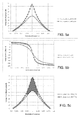
- the antenna bandwidth BW ant is the -3dB bandwidth (cf. left vertical axis) and the signal bandwidth BW sig of the modulated signal to be transmitted via the wireless link established between the transmitter and receiver parts is a bandwidth corresponding to a part of the signal comprising 99% of the signal power (cf. right vertical axis).
- the signal bandwidth BW sig is taken symmetrically around a centre signal frequency f s of the system (preferably identical or close to a resonance frequency f 0 of the narrow band antenna in question)
- the filter transfer functions are altered accordingly (cf. filter transfer functions 1/H' Tx (s) and 1/H' Rx (s) of the Tx- and Rx-filter blocks FILTER(Tx) and FILTER(Rx) in the transmitter and receiver parts, respectively, of the embodiment in FIG. 1 b) , so that the distortion introduced by the antenna blocks (of the frequency translated signals) are compensated for.
- the Tx- as well as the Rx-antenna blocks both have a bandwidth BW ant , which is close to or smaller than a modulation bandwidth BW sig of the modulated signal to be transmitted and received (i.e. the antennas distort the transmitted and received signal, respectively) and that equalization to compensate for the consequent distortion is implemented by equalization filters FILTER (Tx) and FILTER (Rx) in the transmitter and receiver, respectively.
- the compensation for the distortion of the Tx- AND the Rx-antennas may alternatively be performed solely in the receiver or solely in the transmitter.
- only one of the antennas may be a narrowband antenna (i.e. have the property that the antenna bandwidth BW ant is substantially equal to or smaller than a modulation bandwidth BW sig ).
- the antennas are electrically small, i.e. their spatial extension are much smaller than the wavelength ⁇ s of the transmitted signal (e.g. a factor of 10, or 50 or 100 or more, smaller).
- the modulation bandwidth BW sig is correspondingly in the kHz or in the MHz range, e.g. 100 kHz or 1 MHz, respectively.
- the signal wavelength ⁇ s is around 300 m.
- the wavelength in vacuum is around 0.35 m.
- the wavelength in vacuum is around 0.12 m.
- a state of the art portable communication device e.g. a handheld mobile telephone has a maximum outer dimension of the order of 0.10 m.
- a state of the art listening device e.g. a head set has a maximum outer dimension of the order of 0.05 m.
- a state of the art hearing instrument has a maximum outer dimension of the order of 0.01 m. In other words, the smaller the maximum outer dimension of the device (and thus of the antenna) and the lower the signal or carrier frequency, the farther away from a normal efficient antenna you get.
- the ratio of a signal wavelength (30 m) to maximum antenna dimension (0.01 m) is e.g. 3 000.
- the wireless link is based on an inductive coupling between inductive coils in the transmitter and receiver parts of the system.
- the modulation bandwidth BW sig is e.g. larger than or equal to the antenna bandwidth BW ant .
- the system is adapted to provide that k is in the range from 0.1 to 0.75 e.g. in the range from 0.1 to 0.5.
- the modulation or signal bandwidth BW sig is in the range from 50 kHz to 5 MHz.
- the transmitter and/or the receiver parts of the wireless transmission system comprise(s) a signal processing unit operatively coupled to the transmitter and receiver, respectively.
- the signal processing unit is adapted to (at least) process the radio signal (e.g. including performing the equalization and/or calibration and/or trimming tasks (cf. below) of the transmitter and/or the receiver parts in question).
- the performance of the wireless communication system depends on the correspondence between the antenna/tank frequency transfer function and the signal processing applied in the transmitter and receiver (including the equalization filtering for compensating the distortion introduced by the narrow band antenna(s)).
- the antenna blocks cf. e.g. Tx or Rx in FIG. 1
- each comprise the antenna and corresponding resonance elements constituting the antenna-tank circuit (cf. e.g. FIG. 3 ).
- the antenna blocks further comprise a driver or power amplifier (PA) for driving the Tx-antenna and/or a low noise amplifier (LNA) for amplifying the signal from the Rx-antenna, respectively.
- PA driver or power amplifier
- LNA low noise amplifier
- a Tx- and an Rx-antenna of a given device is implemented as one and the same physical antenna.
- the combined Tx- and Rx-antenna of a given device forms part of a transceiver unit comprising appropriate circuitry allowing a switching between a transmit and a receive mode of the transceiver.
- the antenna/tank transfer function tolerances may be relatively large, and may, if not compensated for, degrade the performance of the system.
- the antenna/tank frequency transfer function is calibrated prior to operation of the system, e.g. in a booting routine, when the system is started (powered up).
- the transmitter/receiver signal processing is further adapted to the antenna/tank transfer function.
- a manageable level of Q is taken to mean a level of Q, which the wireless communication system is designed to be able to handle to be able to keep the quality of the transmission and reception within specified limits (e.g. of a quality measure, e.g. BER, e.g. of a received information signal l s ).
- Q is increased by inserting a negative resistance circuit.
- Q is decreased by adding loss to the circuit, e.g. by switching in additional resistance.
- the Q value is intentionally lowered to increase the bandwidth. This can e.g. be of value in a situation where the wireless communication system comprises a programming unit and a unit (e.g.
- a listening device to be programmed by the programming unit, and for which a relatively large transmission bit rate can be valuable.
- the two devices are brought into closer proximity to each other to allow the increased transmission rate to be used with an acceptable quality.
- at bit rate of more than 1 Mbit/s (or more than 1.5 Mbit/s) is established over a relatively short distance, e.g. less than 0.2 m or less than 0.1 m, or less than 0.05 m.
- the antenna/tank circuit can be of any kind which can be represented by a second or higher order transfer function.
- the antenna can be represented by a second order transfer function.
- a wireless communication system comprises the following blocks:
- the idea is based on the observation that the joint frequency response of the antenna and (optionally) the frequency translating block approximately equals that of a first order, real pole, low pass filter in a region around DC.
- FIG. 2 shows relates to the implementation of an appropriate equalization filter for a communication system according to the present application, FIG. 2a showing the pole/zero plot of the antenna, FIG. 2b showing the pole zero plot of the combined antenna and frequency translating block, and FIG. 2c illustrating that the zero of the equalization filter has been added at the same frequency as the equivalent first order real pole filter.
- the narrow band antenna and tuning (or tank) circuit e.g. Tx and/or Rx antenna blocks of FIG. 1
- the narrow band antenna and tuning (or tank) circuit can be represented by a second order transfer function (e.g. the circuit in FIG. 3 ).
- the equalization filters of the transmitter and/or receiver parts (cf. FILTER(Tx) and FILTER(Rx) in FIG. 1 ) of the wireless communication system are implemented according to the principle illustrated in FIG. 2 . Relating to FIG. 1 , FIG. 2a illustrates poles and zeros for the transfer function H Rx (f) for the receiving antenna block ( Rx ).
- FIG. 2a illustrates poles and zeros for the transfer function H Rx (f) for the receiving antenna block ( Rx ).
- FIG. 2b illustrates poles and zeros for the transfer function H Rx ( f' - > f ) for the receiving antenna ( Rx ) and the frequency translation block ( f' -> f ).
- FIG. 2c illustrates poles and zeros for the transfer function H Rx ( f' -> f )* H Eq (f) for the receiving antenna ( Rx ), the frequency translation block ( f' -> f ), and the first order real zero filter H Eq , where the transfer function H Eq ⁇ ( 1/H Rx (f'->f)) inside the modulation bandwidth.
- FIG. 3 shows an example of an antenna/tank circuit.
- FIG. 3 shows an inductive antenna (e.g. a ferrite loaded loop antenna, L ant in FIG. 3 ) resonating with the systems capacitance C1, C2, C3 (e.g. comprising parasitic capacitance and/or intentional capacitance, preferably dominated by intentional capacitance - located on-chip or off-chip, the off-chip capacitance being e.g. SMD capacitance).
- Such an LC resonating system can be both balanced (as shown here, capacitances C1 and C3 being symmetrically coupled to ground GND) or un-balanced.
- FIG. 3 shows an antenna/tank circuit comprising an inductive antenna element L ant (e.g.
- the antenna/tank circuit may just as well comprise a capacitive antenna element C ant (e.g. a patch antenna), the tank circuit in that case including inductive resonance elements (e.g. L1, L2, L3).
- C ant e.g. a patch antenna
- inductive resonance elements e.g. L1, L2, L3
- the communication system is adapted to establish a wireless link between a device comprising a transmitter part and a device comprising a receiver part.
- the wireless link is uni-directional.
- the devices of the communication system can be configured to be both transmitters and receivers (but not at the same time).
- the communication system comprises two or more devices each comprising at least a transmitter part and/or a receiver part.
- the communication system comprises a listening device, e.g. a hearing instrument.
- the communication system comprises an audio gateway for receiving a number of audio signals from a number of audio sources and for transmitting a selected one of the received audio signals to a listening device.
- the wireless link is based on a near-field coupling between to adjacent antennas. In an embodiment, the wireless link is based on far-field (radiated) electromagnetic signals.
- FIG. 4 shows a simplified electric equivalent diagram of an inductive antenna/tank circuit, e.g. the one shown in FIG. 3 .
- the circuit illustrates an embodiment comprising an inductor L P (representing an electrically small loop antenna) in resonance with on-chip capacitance C P , R P being the equivalent parallel resistance of the loop antenna.
- the induced voltage V IN in the loop antenna experiences a passive voltage gain such that the (output, e.g. on-chip) voltage swing V OUT across the capacitor C P is much larger (a result of an impedance transformation).
- the output terminals are e.g. connected to a radio part of an integrated circuit for providing processing of the signal (e.g. including equalization according to the present disclosure, and possibly tuning capacitances for the antenna/tank circuit).
- the total amplitude distortion is 6 dB and the phase distortion is +/- 90 degrees within the band of interest. This amount of distortion invalidates communication using most modulation forms.
- Clearly such a system is useless unless some kind of pre-distortion and/or compensation of the distortion is performed as proposed in this application.
- the signal is between 2 dB and 8 dB higher in the frequency band of interest (see FIG. 5c ). This can e.g. be used to lower the current consumption in the receiver significantly and/or to improve the sensitivity of the communication system (of course under the assumption that the distortion can be handled).
- Another advantage is that ONLY the signal voltage is increased significantly. Undesired interfering signals placed at some distance from the carrier are not magnified so relative to the desired signal they have been attenuated i.e. the effective amount of filtering has been improved.
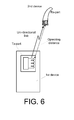
- the transmitting device ( 1 st device ) comprises transmitter part ( Tx-part ) comprising frequency transposition, equalization and Tx-antenna circuit (cf. FIG. 1 ).
- the receiving device ( 2 nd device ) here having the form of a listening device, e.g. a head set or a hearing instrument (here shown as a behind the ear part of a hearing instrument), comprises a receiving part ( Rx-part ) comprising Rx-antenna, frequency transposition, and equalization circuitry (cf. FIG. 1 ).
- the 1 st and 2 nd devices both comprise a signal processing unit ( SP ) adapted for communicating with (or fully or partially form part of) the transmitter and receiver parts of the devices.
- the signal processing units may fully or partially perform the tasks of frequency transposition and equalization.
- the signal processing units are preferably adapted to measure the current resonance frequency f 0 and bandwidth BW ant of the Tx- and Rx-antenna parts, respectively.
- the signal processing units (SP) are further, preferably, adapted to be able to modify (calibrate) the transfer function of the equalization filters ( FILTER-Tx and FILTER-Rx of FIG. 1 ) and/or the tuning of the antenna parts ( Tx , Rx in FIG.
- the calibration is performed at predefined points in time, e.g. regularly, e.g. at a frequency larger than 0.01 Hz, such as larger than 0.1 Hz, such as larger than 1 Hz.
- the calibration frequency is linked to the temperature of the device in question (frequency increasing with increasing temperature).
- the signal processing unit form part of an integrated circuit.
- the integrated circuit further comprises trimming capacitors for use in calibrating the resonance frequency f 0 and bandwidth BW ant of the Tx- and Rx-antenna parts.
- the 1 st device can e.g. be a mobile telephone or an intermediate device (e.g. an audio gateway) between a communication device (e.g. a mobile telephone) or an entertainment device and the 2 nd device .
- the transmitter and receiver parts are adapted so that an excitation of Tx-antenna coil of the Tx-part with a signal to be transmitted results in a magnetic coupling with antenna coil of the Rx-part , when they are located within a predefined distance of each other (indicated by dashed arrow Operating distance , referring to the linear path distance between the Tx- and Rx-parts) and a corresponding reception of the signal in receiver part.
- the wireless link between the 1 st and 2 nd device is indicated to be uni-directional, but may just as well be bi-directional (in which case the 1 st and 2 nd devices each comprise a transmitter and receiver part).
- a protocol for a uni-directional inductive link is e.g. described in US 2005/0255843 A1 .
- An example of a system comprising a hearing instrument and an audio selection device is e.g. described in EP 1 460 769 A1 .
- Inductive communication i.e. communication based on electromagnetic induction as opposed to electromagnetic radiation
- the wireless link may e.g.
- the bandwidth or bit rate of the signal to be transmitted may be adapted to be in the order of hundreds of kHz (kbit/s) or in the order of MHz (Mbit/s).
- the range of the link may be adapted to be in the range from a few centimetres to 10s of meters. In a preferred embodiment, the range is adapted to distances occurring for devices to be worn on a persons' body (e.g. less than 2 m such as less than 1 m, such as less than 0.5 m).
Claims (18)
- Kabelloses Kommunikationssystem, das a) ein erstes Gerät aufweist, das einen Sender-Teil umfasst, welcher eine Tx-Antenne zum Senden eines elektrischen Signals mit einer Signal-Bandbreite BWsig aufweist, und das b) ein zweites Gerät aufweist, das einen Empfänger-Teil umfasst, welcher eine Rx-Antenne zum Empfangen des gesendeten elektromagnetischen Signals aufweist, wobei mindestens eine von den Tx- und Rx-Antennen eine Schmalband-Antenne mit einer Antennen-Bandbreite BWant ist, und wobei die Tx und/oder Rx-Antenne die Relation BWant=k·BWsig erfüllt, und wobei die Antennen-Bandbreite BWant als -3dB Bandbreite der Antenne unter Last bei Vorliegen einer Verbindung zum Kommunikationssystem definiert ist und die Signal-Bandbreite BWsig als diejenige Bandbreite definiert ist, innerhalb der 99% der Signal-Leistung vorliegen, dadurch gekennzeichnet, dass das System ausgebildet ist, ein k, das kleiner oder gleich 0,75 ist, vorzusehen, dass das elektrische Signal entsprechend eines digitalen Modulationsschemas moduliert wird, und dass das kabellose Kommunikationssystem weiterhin mindestens einen Entzerrungsfilter aufweist, der elektrisch mit der Tx- oder mit der Rx-Antenne verbunden ist, wobei der/die Entzerrungsfilter ausgebildet ist/sind, die Amplituden- und/oder Phasen-Verzerrung, die durch die Schmalband-Tx- und/oder Rx-Antennen eingeführt wurde, zu kompensieren.
- Kabelloses Kommunikationssystem gemäß Anspruch 1, bei dem das digitale Modulationsschema aus einer Gruppe ausgewählt, wobei die Gruppe Amplitudenumtastung (ASK), Frequenzumtastung (FSK), Phasenumtastung (PSK), und Quadratur-AmplitudenModulation (QAM) umfasst.
- Kabelloses Kommunikationssystem gemäß Anspruch 1 oder 2, bei dem die Sender- und Empfänger-Teile jeweils weiterhin eine Frequenztranspositions-Einheit aufweisen, die elektrisch mit der Tx- und der Rx-Antenne des entsprechenden Sender- und Empfänger-Teils verbunden sind, wobei die Frequenztranspositions-Einheiten ausgebildet sind, einen Frequenzbereich eines Eingangssignals in einen anderen Frequenzbereich zu überführen, und wobei der/die Entzerrungsfilter ausgebildet ist/sind, die Amplituden- und/oder Phasen-Verzerrung, die durch die Tx- und/oder Rx-Antennen eingeführt wurde, zu kompensieren.
- Kabelloses Kommunikationssystem gemäß Anspruch 2 oder 3, bei dem der/die Entzerrungsfilter durch (einen) Filter erster Ordnung umgesetzt ist/sind, bei dem/denen eine echte Null an ungefähr der gleichen Frequenz liegt, an der die reelle Polstelle der kombinierten Antenne und der Frequenzübertragenden-Abschnitte liegt.
- Kabelloses Kommunikationssystem gemäß einem der Ansprüche 1 bis 4, bei dem die Schmalband-Antenne(n) durch eine Übertragungsfunktion zweiter Ordnung und durch eine Resonanzfrequenz, die gleich der Signal-Frequenz des gesendeten kabellosen Signals ist, repräsentiert werden kann/können.
- Kabelloses Kommunikationssystem gemäß einem der Ansprüche 1 bis 5, bei dem k kleiner oder gleich 0,5 ist.
- Kabelloses Kommunikationssystem gemäß einem der Ansprüche 1 bis 6, bei dem der Sender- und der Empfänger-Teil ausgebildet sind, eine kabellose Verknüpfung basierend auf einer induktiven Kopplung zwischen der sendenden und der empfangenden Antenne zu realisieren.
- Kabelloses Kommunikationssystem gemäß einem der Ansprüche 1 bis 7, bei dem mindestens eine der Schmalband-Antennen eine elektrisch kleine Antenne ist.
- Kabelloses Kommunikationssystem gemäß einem der Ansprüche 1 bis 8, das ausgebildet vorzusehen, dass eine Resonanzfrequenz f0 der Tx und/oder der Rx-Antenne auf einen gewünschten Wert innerhalb eines vorbestimmten Bereichs an Resonanzfrequenzen abgestimmt werden kann.
- Kabelloses Kommunikationssystem gemäß Anspruch 9, bei dem der Sender und/oder der Empfänger-Teil eine Anzahl von Trimmkondensatoren zum Bereitstellen der Abstimmbarkeit der Resonanzfrequenz aufweisen.
- Kabelloses Kommunikationssystem gemäß einem der Ansprüche 1 bis 10, das zwei oder mehr Geräte aufweist, von denen jedes mindestens einen Sender-Teil oder einen Empfänger-Teil umfasst.
- Kabelloses Kommunikationssystem gemäß einem der Ansprüche 1 bis 11, bei dem das erste und das zweite Gerät jeweils einen Sender-Teil und einen Empfänger-Teil aufweisen.
- Kabelloses Kommunikationssystem gemäß einem der Ansprüche 1 bis 12, bei dem der Empfänger-Teil und/oder der Sender-Teil einen Messschaltkreis aufweisen, der ausgebildet ist die Abstimmungsfrequenz und/oder die Bandbreite der Antennen und des Abstimmschaltkreises zu messen, und bei dem der Teil ausgebildet ist, die Kompensation durch die/den Entzerrungsfilter und/oder die Abstimmung der Antenne abhängig von den gemessenen Werten einzustellen.
- Verfahren zum Betreiben eines kabellosen Kommunikationssystems, wobei das System aufweist:a) ein erstes Gerät, das einen Sender-Teil aufweist, der eine Tx-Antenne zum Senden eines elektrischen Signals mit einer Signal-Bandbreite BWsig umfasst;b) ein zweites Gerät, das einen Empfänger-Teil aufweist, der eine Rx-Antenne zum Empfangen des gesendeten elektromagnetischen Signals umfasst;wobei das Verfahren aufweistA) Vorsehen, dass mindestens eine der Tx- und Rx-Antennen eine Schmalband-Antenne mit einer Antennen-Bandbreite BWant ist, wobei die Tx- und/oder Rx-Antennen-Bandbreiten die Relation BWant=k·BWsig erfüllen;
wobei die Antennenbandbreite BWant als -3dB Bandbreite der Antenne unter Last bei Vorliegen einer Verbindung zum Kommunikationssystem definiert ist und die Signal-Bandbreite BWsig als diejenige Bandbreite definiert ist, mit der 99% der Signal-Leistung lokalisiert sind,
dadurch gekennzeichnet, dass das Verfahren weiterhin aufweistB) Vorsehen, dass k kleiner oder gleich 0,75 ist;C) Vorsehen, dass das gesendete und/oder empfangene elektromagnetische Signal in einer Weise verarbeitet wird, die die Amplituden- und/oder Phasen-Verzerrung der Schmalband-Antenne(n) kompensiert,
und wobei das elektrische Signal entsprechend eines digitalen Modulationsschemas moduliert wird. - Verfahren gemäß Anspruch 14, welches ein Kalibrieren der Schmalband-Antennen/Tank-Frequenz Übertragungsfunktion im Betrieb des kabellosen Kommunikationssystems umfasst.
- Verfahren gemäß Anspruch 15, bei dem die Tx- und Rx-Antennen-Frequenz Übertragungsfunktionen jeweils durch zwei Parameter gekennzeichnet sind, 1) die Resonanzfrequenz f0 und 2) den Gütefaktor Q, wobei das Verfahren aufweista. Vorsehen, dass die Resonanzfrequenz f0 auf einen gewünschten Wert abgestimmt wird; undb. Vorsehen, dass die Kompensierung der Amplituden- und/oder Phasen-Verzerrung der Schmalband-Antenne(n) entsprechend dem Gütefaktor Q der jeweiligen Tx- und Rx-Antenne ausgebildet ist.
- Verfahren gemäß Anspruch 16, welches weiterhin aufweist, dass der Wert für Q auf ein geeignetes Niveau eingestellt wird, in welchem das kabellose Kommunikationssystem ausgebildet ist damit umgehen zu können, die Qualität des Sendens und des Empfangens in bestimmten Grenzen zu halten.
- Verfahren gemäß Anspruch 16 oder 17, welches vorsieht, dass die Signalverarbeitung an den Gütefaktor Q von Antenne/Tank durch eine automatische Routine angepasst wird, z.B. ausgeführt während eines Systemstarts, und/oder an vorbestimmten Zeitpunkten, und/oder auf Anfrage eines Nutzers.
Priority Applications (7)
| Application Number | Priority Date | Filing Date | Title |
|---|---|---|---|
| DK15193658.0T DK3012982T3 (da) | 2010-03-10 | 2010-03-10 | Radiofrekvenssender og modtagerdele med en modulationsbåndbredde, der kan sammenlignes med eller overstiger båndbredden for sender- og/eller modtagerantennerne |
| EP10156029.0A EP2367294B1 (de) | 2010-03-10 | 2010-03-10 | Drahtloses Kommunikationssystem mit einer höheren Modulationsbandbreite als die Bandbreite der Sender- und/oder Empfängerantennen |
| EP15193658.0A EP3012982B1 (de) | 2010-03-10 | 2010-03-10 | Funkfrequenzsender und empfängerteile mit einer ähnlichen oder höheren bandbreite als derjenigen des senders und/oder der empfängerantennen |
| DK10156029.0T DK2367294T3 (en) | 2010-03-10 | 2010-03-10 | Wireless communication system with a modulation bandwidth that exceeds the bandwidth for transmitting and / or receiving antenna |
| AU2011201005A AU2011201005B2 (en) | 2010-03-10 | 2011-03-08 | Wireless communication system with a modulation bandwidth comparable to or exceeding the bandwidth of the transmitter and/or receiver antennas |
| US13/043,271 US8514965B2 (en) | 2010-03-10 | 2011-03-08 | Wireless communication system with a modulation bandwidth comparable to or exceeding the bandwidth of the transmitter and/or receiver antennas |
| CN201110062189.3A CN102195662B (zh) | 2010-03-10 | 2011-03-10 | 具有调制带宽相当于或超过发送器和/或接收器天线带宽的无线通信系统 |
Applications Claiming Priority (1)
| Application Number | Priority Date | Filing Date | Title |
|---|---|---|---|
| EP10156029.0A EP2367294B1 (de) | 2010-03-10 | 2010-03-10 | Drahtloses Kommunikationssystem mit einer höheren Modulationsbandbreite als die Bandbreite der Sender- und/oder Empfängerantennen |
Related Child Applications (1)
| Application Number | Title | Priority Date | Filing Date |
|---|---|---|---|
| EP15193658.0A Division EP3012982B1 (de) | 2010-03-10 | 2010-03-10 | Funkfrequenzsender und empfängerteile mit einer ähnlichen oder höheren bandbreite als derjenigen des senders und/oder der empfängerantennen |
Publications (2)
| Publication Number | Publication Date |
|---|---|
| EP2367294A1 EP2367294A1 (de) | 2011-09-21 |
| EP2367294B1 true EP2367294B1 (de) | 2015-11-11 |
Family
ID=42597502
Family Applications (2)
| Application Number | Title | Priority Date | Filing Date |
|---|---|---|---|
| EP15193658.0A Active EP3012982B1 (de) | 2010-03-10 | 2010-03-10 | Funkfrequenzsender und empfängerteile mit einer ähnlichen oder höheren bandbreite als derjenigen des senders und/oder der empfängerantennen |
| EP10156029.0A Active EP2367294B1 (de) | 2010-03-10 | 2010-03-10 | Drahtloses Kommunikationssystem mit einer höheren Modulationsbandbreite als die Bandbreite der Sender- und/oder Empfängerantennen |
Family Applications Before (1)
| Application Number | Title | Priority Date | Filing Date |
|---|---|---|---|
| EP15193658.0A Active EP3012982B1 (de) | 2010-03-10 | 2010-03-10 | Funkfrequenzsender und empfängerteile mit einer ähnlichen oder höheren bandbreite als derjenigen des senders und/oder der empfängerantennen |
Country Status (5)
| Country | Link |
|---|---|
| US (1) | US8514965B2 (de) |
| EP (2) | EP3012982B1 (de) |
| CN (1) | CN102195662B (de) |
| AU (1) | AU2011201005B2 (de) |
| DK (2) | DK3012982T3 (de) |
Families Citing this family (30)
| Publication number | Priority date | Publication date | Assignee | Title |
|---|---|---|---|---|
| US9432780B2 (en) | 2010-07-03 | 2016-08-30 | Starkey Laboratories, Inc. | Multi-mode radio for hearing assistance devices |
| JP5071574B1 (ja) | 2011-07-05 | 2012-11-14 | ソニー株式会社 | 検知装置、受電装置、非接触電力伝送システム及び検知方法 |
| DK2579460T3 (da) | 2011-10-06 | 2014-08-04 | Oticon As | HF sender til elektrisk kort antenne |
| US9397385B2 (en) * | 2011-11-09 | 2016-07-19 | Qualcomm Technologies International, Ltd. | Near field communications reader |
| DK2775616T3 (da) | 2011-11-25 | 2019-11-11 | Oticon As | HF-sender til elektrisk kort antenne |
| EP2706660B1 (de) * | 2012-09-05 | 2015-11-25 | Swiss Timing Ltd. | Vorrichtung zum Senden von Datensignalen und/oder Steuern mit Antennenanordnungen |
| US9185659B2 (en) * | 2012-10-25 | 2015-11-10 | Qualcomm Incorporated | Two-dimensional transmit power compensation |
| EP2736178A1 (de) * | 2012-11-27 | 2014-05-28 | ST-Ericsson SA | Vorverzerrung des Übertragungssignals eines NFC-Lesers |
| DK2750408T3 (da) | 2012-12-28 | 2019-06-11 | Gn Hearing As | Høreapparat med en adaptiv antennetilpasningsmekanisme og en fremgangsmåde til adaptiv tilpasning af en høreapparatantenne |
| CN104956601A (zh) * | 2013-02-07 | 2015-09-30 | 唯听助听器公司 | 用于助听器的收发器和操作这种收发器的方法 |
| US9515815B2 (en) | 2013-03-15 | 2016-12-06 | Tm Ip Holdings, Llc | Transpositional modulation systems, methods and devices |
| US9014293B2 (en) | 2013-03-15 | 2015-04-21 | Tm Ip Holdings, Llc | Transpositional modulation systems and methods |
| US9252823B2 (en) * | 2013-08-06 | 2016-02-02 | Purdue Research Foundation | Phase compensation filtering for multipath wireless systems |
| US9705617B2 (en) * | 2013-08-08 | 2017-07-11 | Massoud Alibakhsh | System and method for wirelessly transmitting and receiving customized data broadcasts |
| EP2835986B1 (de) * | 2013-08-09 | 2017-10-11 | Oticon A/s | Hörgerät mit Eingangswandler und drahtlosem Empfänger |
| EP2869599B1 (de) | 2013-11-05 | 2020-10-21 | Oticon A/s | Binaurales Hörgerätesystem mit einer Datenbank von kopfbezogenen Übertragungsfunktionen |
| EP3713254A3 (de) | 2013-11-07 | 2020-11-18 | Oticon A/s | Binaurales hörgerätesystem mit zwei drahtlosen schnittstellen |
| EP2988427B1 (de) * | 2014-08-22 | 2019-04-24 | STMicroelectronics International N.V. | Verfahren für eine Phasenkalibrierung in einer Frontendschaltung einer Nahfeldkommunikation, NFC, Etikettierungsvorrichtung, Frontendschaltung einer NFC-Etikettierungsvorrichtung |
| WO2016081894A1 (en) * | 2014-11-21 | 2016-05-26 | Virginia Tech Intellectual Properties, Inc. | Transmitting wideband signals through an electrically small antenna using antenna modulation |
| EP3054706A3 (de) | 2015-02-09 | 2016-12-07 | Oticon A/s | Binaurales hörsystem und hörgerät mit einer strahlformungseinheit |
| DK3107315T3 (da) | 2015-06-09 | 2019-11-11 | Oticon As | Høreanordning, der omfatter en signalgenerator til maskering af tinnitus |
| JP2018174360A (ja) * | 2015-09-08 | 2018-11-08 | パナソニックIpマネジメント株式会社 | 非接触通信システム |
| CN106936467B (zh) * | 2015-12-30 | 2020-04-03 | 中国船舶重工集团公司第七研究院 | 一种窄带天线发射系统实现快速换频的方法 |
| DK3337190T3 (da) | 2016-12-13 | 2021-05-03 | Oticon As | Fremgangsmåde til reducering af støj i en audiobehandlingsanordning |
| US9882764B1 (en) | 2017-04-13 | 2018-01-30 | Tm Ip Holdings, Llc | Transpositional modulation |
| US10578709B1 (en) | 2017-04-20 | 2020-03-03 | Tm Ip Holdings, Llc | Transpositional modulation for defensive measures |
| US10341161B2 (en) | 2017-07-10 | 2019-07-02 | Tm Ip Holdings, Llc | Multi-dimensional signal encoding |
| US11695213B2 (en) | 2017-12-21 | 2023-07-04 | Cochlear Limited | Antenna for wireless communications integrated in electronic device |
| WO2019236746A1 (en) | 2018-06-05 | 2019-12-12 | Tm Ip Holdings, Llc | Transpositional modulation and demodulation |
| DE102018212957B3 (de) | 2018-08-02 | 2020-01-02 | Fraunhofer-Gesellschaft zur Förderung der angewandten Forschung e.V. | Übertragung von daten von einem benutzerendgerät zu einem anderen gerät |
Family Cites Families (15)
| Publication number | Priority date | Publication date | Assignee | Title |
|---|---|---|---|---|
| US4194154A (en) * | 1976-03-01 | 1980-03-18 | Kahn Leonard R | Narrow bandwidth network compensation method and apparatus |
| CA1276992C (en) | 1986-09-26 | 1990-11-27 | Andrew E. Mcgirr | Electronically controlled matching circuit |
| US5491715A (en) * | 1993-06-28 | 1996-02-13 | Texas Instruments Deutschland Gmbh | Automatic antenna tuning method and circuit |
| US6424820B1 (en) * | 1999-04-02 | 2002-07-23 | Interval Research Corporation | Inductively coupled wireless system and method |
| JP2001160770A (ja) | 1999-12-02 | 2001-06-12 | Sony Corp | デジタルデータ伝送装置 |
| US20020183013A1 (en) * | 2001-05-25 | 2002-12-05 | Auckland David T. | Programmable radio frequency sub-system with integrated antennas and filters and wireless communication device using same |
| EP1460769B1 (de) | 2003-03-18 | 2007-04-04 | Phonak Communications Ag | Mobiler Transceiver und Elektronikmodul zur Steuerung des Transceivers |
| DE10323219B3 (de) * | 2003-05-22 | 2004-12-09 | Siemens Audiologische Technik Gmbh | Sendespulensystem und Fernbedienung für ein Hörhilfsgerät |
| US6940466B2 (en) | 2003-11-25 | 2005-09-06 | Starkey Laboratories, Inc. | Enhanced magnetic field communication system |
| US7512383B2 (en) | 2003-11-26 | 2009-03-31 | Starkey Laboratories, Inc. | Transmit-receive switching in wireless hearing aids |
| US7529565B2 (en) * | 2004-04-08 | 2009-05-05 | Starkey Laboratories, Inc. | Wireless communication protocol |
| DE602005012516D1 (de) * | 2005-10-20 | 2009-03-12 | Oticon As | System und Verfahren zur Antennenansteuerung |
| US20080158076A1 (en) | 2006-12-28 | 2008-07-03 | Broadcom Corporation | Dynamically adjustable narrow bandwidth antenna for wide band systems |
| TWI349266B (en) * | 2007-04-13 | 2011-09-21 | Qisda Corp | Voice recognition system and method |
| JP2009206555A (ja) * | 2008-02-26 | 2009-09-10 | Nsc Co Ltd | 受信機 |
-
2010
- 2010-03-10 DK DK15193658.0T patent/DK3012982T3/da active
- 2010-03-10 DK DK10156029.0T patent/DK2367294T3/en active
- 2010-03-10 EP EP15193658.0A patent/EP3012982B1/de active Active
- 2010-03-10 EP EP10156029.0A patent/EP2367294B1/de active Active
-
2011
- 2011-03-08 AU AU2011201005A patent/AU2011201005B2/en not_active Ceased
- 2011-03-08 US US13/043,271 patent/US8514965B2/en active Active
- 2011-03-10 CN CN201110062189.3A patent/CN102195662B/zh active Active
Also Published As
| Publication number | Publication date |
|---|---|
| DK2367294T3 (en) | 2016-02-22 |
| EP3012982B1 (de) | 2020-05-27 |
| AU2011201005B2 (en) | 2016-07-07 |
| AU2011201005A1 (en) | 2011-09-29 |
| CN102195662A (zh) | 2011-09-21 |
| US20110222621A1 (en) | 2011-09-15 |
| EP3012982A1 (de) | 2016-04-27 |
| US8514965B2 (en) | 2013-08-20 |
| DK3012982T3 (da) | 2020-07-20 |
| CN102195662B (zh) | 2015-07-08 |
| EP2367294A1 (de) | 2011-09-21 |
Similar Documents
| Publication | Publication Date | Title |
|---|---|---|
| EP2367294B1 (de) | Drahtloses Kommunikationssystem mit einer höheren Modulationsbandbreite als die Bandbreite der Sender- und/oder Empfängerantennen | |
| US9300367B2 (en) | Receiver and method for retrieving an information signal from a magnetic induction signal | |
| US8923789B2 (en) | Method of diminishing the minimum range of operation of a communication link | |
| US9054773B2 (en) | Apparatus comprising a broadcast receiver circuit and provided with an antenna | |
| EP2661909B1 (de) | Hörhilfesystem mit dualmodus-drahtlosfunk | |
| CA2546874A1 (en) | Resonance frequency shift canceling in wireless hearing aids | |
| US11653159B2 (en) | Hearing instrument comprising a battery antenna | |
| AU2011203025A1 (en) | High Voltage Swing Input/Output Enabled in a Standard IC Process Using Passive Impedance Transformation | |
| AU2012254960A1 (en) | RF Transmitter for Electrically Short Antenna | |
| US9014245B2 (en) | Method and apparatus for compensating for phase shift in a communication device | |
| AU2012238219B2 (en) | RF Transmitter for Electrically Short Antenna | |
| US11076244B2 (en) | Hearing instrument having a digitally tunable antenna | |
| US20220386043A9 (en) | Hearing instrument comprising a parasitic battery antenna element | |
| US10869143B2 (en) | Hearing instrument comprising a parasitic battery antenna element | |
| CN116668927A (zh) | 听力设备 |
Legal Events
| Date | Code | Title | Description |
|---|---|---|---|
| PUAI | Public reference made under article 153(3) epc to a published international application that has entered the european phase |
Free format text: ORIGINAL CODE: 0009012 |
|
| AK | Designated contracting states |
Kind code of ref document: A1 Designated state(s): AT BE BG CH CY CZ DE DK EE ES FI FR GB GR HR HU IE IS IT LI LT LU LV MC MK MT NL NO PL PT RO SE SI SK SM TR |
|
| AX | Request for extension of the european patent |
Extension state: AL BA ME RS |
|
| 17P | Request for examination filed |
Effective date: 20120321 |
|
| 17Q | First examination report despatched |
Effective date: 20130619 |
|
| GRAP | Despatch of communication of intention to grant a patent |
Free format text: ORIGINAL CODE: EPIDOSNIGR1 |
|
| RIC1 | Information provided on ipc code assigned before grant |
Ipc: H04B 5/00 20060101AFI20150513BHEP Ipc: H04B 5/06 20060101ALI20150513BHEP Ipc: H04R 25/00 20060101ALI20150513BHEP |
|
| INTG | Intention to grant announced |
Effective date: 20150529 |
|
| GRAS | Grant fee paid |
Free format text: ORIGINAL CODE: EPIDOSNIGR3 |
|
| GRAA | (expected) grant |
Free format text: ORIGINAL CODE: 0009210 |
|
| AK | Designated contracting states |
Kind code of ref document: B1 Designated state(s): AT BE BG CH CY CZ DE DK EE ES FI FR GB GR HR HU IE IS IT LI LT LU LV MC MK MT NL NO PL PT RO SE SI SK SM TR |
|
| REG | Reference to a national code |
Ref country code: GB Ref legal event code: FG4D |
|
| REG | Reference to a national code |
Ref country code: CH Ref legal event code: EP |
|
| REG | Reference to a national code |
Ref country code: IE Ref legal event code: FG4D |
|
| REG | Reference to a national code |
Ref country code: AT Ref legal event code: REF Ref document number: 760905 Country of ref document: AT Kind code of ref document: T Effective date: 20151215 |
|
| REG | Reference to a national code |
Ref country code: DE Ref legal event code: R096 Ref document number: 602010028906 Country of ref document: DE |
|
| REG | Reference to a national code |
Ref country code: DK Ref legal event code: T3 Effective date: 20160216 |
|
| REG | Reference to a national code |
Ref country code: LT Ref legal event code: MG4D |
|
| REG | Reference to a national code |
Ref country code: NL Ref legal event code: MP Effective date: 20160211 |
|
| REG | Reference to a national code |
Ref country code: FR Ref legal event code: PLFP Year of fee payment: 7 |
|
| REG | Reference to a national code |
Ref country code: AT Ref legal event code: MK05 Ref document number: 760905 Country of ref document: AT Kind code of ref document: T Effective date: 20151111 |
|
| PG25 | Lapsed in a contracting state [announced via postgrant information from national office to epo] |
Ref country code: NO Free format text: LAPSE BECAUSE OF FAILURE TO SUBMIT A TRANSLATION OF THE DESCRIPTION OR TO PAY THE FEE WITHIN THE PRESCRIBED TIME-LIMIT Effective date: 20160211 Ref country code: IS Free format text: LAPSE BECAUSE OF FAILURE TO SUBMIT A TRANSLATION OF THE DESCRIPTION OR TO PAY THE FEE WITHIN THE PRESCRIBED TIME-LIMIT Effective date: 20160311 Ref country code: ES Free format text: LAPSE BECAUSE OF FAILURE TO SUBMIT A TRANSLATION OF THE DESCRIPTION OR TO PAY THE FEE WITHIN THE PRESCRIBED TIME-LIMIT Effective date: 20151111 Ref country code: IT Free format text: LAPSE BECAUSE OF FAILURE TO SUBMIT A TRANSLATION OF THE DESCRIPTION OR TO PAY THE FEE WITHIN THE PRESCRIBED TIME-LIMIT Effective date: 20151111 Ref country code: HR Free format text: LAPSE BECAUSE OF FAILURE TO SUBMIT A TRANSLATION OF THE DESCRIPTION OR TO PAY THE FEE WITHIN THE PRESCRIBED TIME-LIMIT Effective date: 20151111 Ref country code: NL Free format text: LAPSE BECAUSE OF FAILURE TO SUBMIT A TRANSLATION OF THE DESCRIPTION OR TO PAY THE FEE WITHIN THE PRESCRIBED TIME-LIMIT Effective date: 20151111 Ref country code: LT Free format text: LAPSE BECAUSE OF FAILURE TO SUBMIT A TRANSLATION OF THE DESCRIPTION OR TO PAY THE FEE WITHIN THE PRESCRIBED TIME-LIMIT Effective date: 20151111 |
|
| PG25 | Lapsed in a contracting state [announced via postgrant information from national office to epo] |
Ref country code: PL Free format text: LAPSE BECAUSE OF FAILURE TO SUBMIT A TRANSLATION OF THE DESCRIPTION OR TO PAY THE FEE WITHIN THE PRESCRIBED TIME-LIMIT Effective date: 20151111 Ref country code: GR Free format text: LAPSE BECAUSE OF FAILURE TO SUBMIT A TRANSLATION OF THE DESCRIPTION OR TO PAY THE FEE WITHIN THE PRESCRIBED TIME-LIMIT Effective date: 20160212 Ref country code: SE Free format text: LAPSE BECAUSE OF FAILURE TO SUBMIT A TRANSLATION OF THE DESCRIPTION OR TO PAY THE FEE WITHIN THE PRESCRIBED TIME-LIMIT Effective date: 20151111 Ref country code: LV Free format text: LAPSE BECAUSE OF FAILURE TO SUBMIT A TRANSLATION OF THE DESCRIPTION OR TO PAY THE FEE WITHIN THE PRESCRIBED TIME-LIMIT Effective date: 20151111 Ref country code: AT Free format text: LAPSE BECAUSE OF FAILURE TO SUBMIT A TRANSLATION OF THE DESCRIPTION OR TO PAY THE FEE WITHIN THE PRESCRIBED TIME-LIMIT Effective date: 20151111 Ref country code: PT Free format text: LAPSE BECAUSE OF FAILURE TO SUBMIT A TRANSLATION OF THE DESCRIPTION OR TO PAY THE FEE WITHIN THE PRESCRIBED TIME-LIMIT Effective date: 20160311 Ref country code: FI Free format text: LAPSE BECAUSE OF FAILURE TO SUBMIT A TRANSLATION OF THE DESCRIPTION OR TO PAY THE FEE WITHIN THE PRESCRIBED TIME-LIMIT Effective date: 20151111 |
|
| PG25 | Lapsed in a contracting state [announced via postgrant information from national office to epo] |
Ref country code: CZ Free format text: LAPSE BECAUSE OF FAILURE TO SUBMIT A TRANSLATION OF THE DESCRIPTION OR TO PAY THE FEE WITHIN THE PRESCRIBED TIME-LIMIT Effective date: 20151111 |
|
| REG | Reference to a national code |
Ref country code: DE Ref legal event code: R097 Ref document number: 602010028906 Country of ref document: DE |
|
| PG25 | Lapsed in a contracting state [announced via postgrant information from national office to epo] |
Ref country code: SM Free format text: LAPSE BECAUSE OF FAILURE TO SUBMIT A TRANSLATION OF THE DESCRIPTION OR TO PAY THE FEE WITHIN THE PRESCRIBED TIME-LIMIT Effective date: 20151111 Ref country code: BE Free format text: LAPSE BECAUSE OF NON-PAYMENT OF DUE FEES Effective date: 20160331 Ref country code: EE Free format text: LAPSE BECAUSE OF FAILURE TO SUBMIT A TRANSLATION OF THE DESCRIPTION OR TO PAY THE FEE WITHIN THE PRESCRIBED TIME-LIMIT Effective date: 20151111 Ref country code: SK Free format text: LAPSE BECAUSE OF FAILURE TO SUBMIT A TRANSLATION OF THE DESCRIPTION OR TO PAY THE FEE WITHIN THE PRESCRIBED TIME-LIMIT Effective date: 20151111 Ref country code: RO Free format text: LAPSE BECAUSE OF FAILURE TO SUBMIT A TRANSLATION OF THE DESCRIPTION OR TO PAY THE FEE WITHIN THE PRESCRIBED TIME-LIMIT Effective date: 20151111 |
|
| PLBE | No opposition filed within time limit |
Free format text: ORIGINAL CODE: 0009261 |
|
| STAA | Information on the status of an ep patent application or granted ep patent |
Free format text: STATUS: NO OPPOSITION FILED WITHIN TIME LIMIT |
|
| 26N | No opposition filed |
Effective date: 20160812 |
|
| PG25 | Lapsed in a contracting state [announced via postgrant information from national office to epo] |
Ref country code: LU Free format text: LAPSE BECAUSE OF FAILURE TO SUBMIT A TRANSLATION OF THE DESCRIPTION OR TO PAY THE FEE WITHIN THE PRESCRIBED TIME-LIMIT Effective date: 20160310 Ref country code: MC Free format text: LAPSE BECAUSE OF FAILURE TO SUBMIT A TRANSLATION OF THE DESCRIPTION OR TO PAY THE FEE WITHIN THE PRESCRIBED TIME-LIMIT Effective date: 20151111 |
|
| PG25 | Lapsed in a contracting state [announced via postgrant information from national office to epo] |
Ref country code: SI Free format text: LAPSE BECAUSE OF FAILURE TO SUBMIT A TRANSLATION OF THE DESCRIPTION OR TO PAY THE FEE WITHIN THE PRESCRIBED TIME-LIMIT Effective date: 20151111 |
|
| REG | Reference to a national code |
Ref country code: IE Ref legal event code: MM4A |
|
| PG25 | Lapsed in a contracting state [announced via postgrant information from national office to epo] |
Ref country code: BE Free format text: LAPSE BECAUSE OF FAILURE TO SUBMIT A TRANSLATION OF THE DESCRIPTION OR TO PAY THE FEE WITHIN THE PRESCRIBED TIME-LIMIT Effective date: 20151111 |
|
| PG25 | Lapsed in a contracting state [announced via postgrant information from national office to epo] |
Ref country code: IE Free format text: LAPSE BECAUSE OF NON-PAYMENT OF DUE FEES Effective date: 20160310 |
|
| REG | Reference to a national code |
Ref country code: FR Ref legal event code: PLFP Year of fee payment: 8 |
|
| PG25 | Lapsed in a contracting state [announced via postgrant information from national office to epo] |
Ref country code: MT Free format text: LAPSE BECAUSE OF FAILURE TO SUBMIT A TRANSLATION OF THE DESCRIPTION OR TO PAY THE FEE WITHIN THE PRESCRIBED TIME-LIMIT Effective date: 20151111 |
|
| REG | Reference to a national code |
Ref country code: FR Ref legal event code: PLFP Year of fee payment: 9 |
|
| PG25 | Lapsed in a contracting state [announced via postgrant information from national office to epo] |
Ref country code: HU Free format text: LAPSE BECAUSE OF FAILURE TO SUBMIT A TRANSLATION OF THE DESCRIPTION OR TO PAY THE FEE WITHIN THE PRESCRIBED TIME-LIMIT; INVALID AB INITIO Effective date: 20100310 Ref country code: CY Free format text: LAPSE BECAUSE OF FAILURE TO SUBMIT A TRANSLATION OF THE DESCRIPTION OR TO PAY THE FEE WITHIN THE PRESCRIBED TIME-LIMIT Effective date: 20151111 |
|
| PG25 | Lapsed in a contracting state [announced via postgrant information from national office to epo] |
Ref country code: MT Free format text: LAPSE BECAUSE OF FAILURE TO SUBMIT A TRANSLATION OF THE DESCRIPTION OR TO PAY THE FEE WITHIN THE PRESCRIBED TIME-LIMIT Effective date: 20160331 Ref country code: TR Free format text: LAPSE BECAUSE OF FAILURE TO SUBMIT A TRANSLATION OF THE DESCRIPTION OR TO PAY THE FEE WITHIN THE PRESCRIBED TIME-LIMIT Effective date: 20151111 Ref country code: MK Free format text: LAPSE BECAUSE OF FAILURE TO SUBMIT A TRANSLATION OF THE DESCRIPTION OR TO PAY THE FEE WITHIN THE PRESCRIBED TIME-LIMIT Effective date: 20151111 |
|
| PG25 | Lapsed in a contracting state [announced via postgrant information from national office to epo] |
Ref country code: BG Free format text: LAPSE BECAUSE OF FAILURE TO SUBMIT A TRANSLATION OF THE DESCRIPTION OR TO PAY THE FEE WITHIN THE PRESCRIBED TIME-LIMIT Effective date: 20151111 |
|
| PGFP | Annual fee paid to national office [announced via postgrant information from national office to epo] |
Ref country code: FR Payment date: 20230228 Year of fee payment: 14 Ref country code: DK Payment date: 20230228 Year of fee payment: 14 |
|
| PGFP | Annual fee paid to national office [announced via postgrant information from national office to epo] |
Ref country code: GB Payment date: 20230228 Year of fee payment: 14 Ref country code: DE Payment date: 20230302 Year of fee payment: 14 |
|
| PGFP | Annual fee paid to national office [announced via postgrant information from national office to epo] |
Ref country code: CH Payment date: 20230402 Year of fee payment: 14 |