EP2367285A1 - A sample-and-hold amplifier - Google Patents
A sample-and-hold amplifier Download PDFInfo
- Publication number
- EP2367285A1 EP2367285A1 EP10250528A EP10250528A EP2367285A1 EP 2367285 A1 EP2367285 A1 EP 2367285A1 EP 10250528 A EP10250528 A EP 10250528A EP 10250528 A EP10250528 A EP 10250528A EP 2367285 A1 EP2367285 A1 EP 2367285A1
- Authority
- EP
- European Patent Office
- Prior art keywords
- sample
- amplifier
- hold
- phase
- during
- Prior art date
- Legal status (The legal status is an assumption and is not a legal conclusion. Google has not performed a legal analysis and makes no representation as to the accuracy of the status listed.)
- Granted
Links
Images


Classifications
-
- H—ELECTRICITY
- H03—ELECTRONIC CIRCUITRY
- H03F—AMPLIFIERS
- H03F3/00—Amplifiers with only discharge tubes or only semiconductor devices as amplifying elements
- H03F3/005—Amplifiers with only discharge tubes or only semiconductor devices as amplifying elements using switched capacitors, e.g. dynamic amplifiers; using switched capacitors as resistors in differential amplifiers
-
- H—ELECTRICITY
- H03—ELECTRONIC CIRCUITRY
- H03F—AMPLIFIERS
- H03F3/00—Amplifiers with only discharge tubes or only semiconductor devices as amplifying elements
- H03F3/45—Differential amplifiers
- H03F3/45071—Differential amplifiers with semiconductor devices only
- H03F3/45076—Differential amplifiers with semiconductor devices only characterised by the way of implementation of the active amplifying circuit in the differential amplifier
- H03F3/45475—Differential amplifiers with semiconductor devices only characterised by the way of implementation of the active amplifying circuit in the differential amplifier using IC blocks as the active amplifying circuit
-
- H—ELECTRICITY
- H03—ELECTRONIC CIRCUITRY
- H03F—AMPLIFIERS
- H03F2200/00—Indexing scheme relating to amplifiers
- H03F2200/129—Indexing scheme relating to amplifiers there being a feedback over the complete amplifier
-
- H—ELECTRICITY
- H03—ELECTRONIC CIRCUITRY
- H03F—AMPLIFIERS
- H03F2200/00—Indexing scheme relating to amplifiers
- H03F2200/135—Indexing scheme relating to amplifiers there being a feedback over one or more internal stages in the global amplifier
-
- H—ELECTRICITY
- H03—ELECTRONIC CIRCUITRY
- H03F—AMPLIFIERS
- H03F2200/00—Indexing scheme relating to amplifiers
- H03F2200/156—One or more switches are realised in the feedback circuit of the amplifier stage
-
- H—ELECTRICITY
- H03—ELECTRONIC CIRCUITRY
- H03F—AMPLIFIERS
- H03F2200/00—Indexing scheme relating to amplifiers
- H03F2200/159—Indexing scheme relating to amplifiers the feedback circuit being closed during a switching time
-
- H—ELECTRICITY
- H03—ELECTRONIC CIRCUITRY
- H03F—AMPLIFIERS
- H03F2203/00—Indexing scheme relating to amplifiers with only discharge tubes or only semiconductor devices as amplifying elements covered by H03F3/00
- H03F2203/45—Indexing scheme relating to differential amplifiers
- H03F2203/45512—Indexing scheme relating to differential amplifiers the FBC comprising one or more capacitors, not being switched capacitors, and being coupled between the LC and the IC
-
- H—ELECTRICITY
- H03—ELECTRONIC CIRCUITRY
- H03F—AMPLIFIERS
- H03F2203/00—Indexing scheme relating to amplifiers with only discharge tubes or only semiconductor devices as amplifying elements covered by H03F3/00
- H03F2203/45—Indexing scheme relating to differential amplifiers
- H03F2203/45514—Indexing scheme relating to differential amplifiers the FBC comprising one or more switched capacitors, and being coupled between the LC and the IC
-
- H—ELECTRICITY
- H03—ELECTRONIC CIRCUITRY
- H03F—AMPLIFIERS
- H03F2203/00—Indexing scheme relating to amplifiers with only discharge tubes or only semiconductor devices as amplifying elements covered by H03F3/00
- H03F2203/45—Indexing scheme relating to differential amplifiers
- H03F2203/45534—Indexing scheme relating to differential amplifiers the FBC comprising multiple switches and being coupled between the LC and the IC
-
- H—ELECTRICITY
- H03—ELECTRONIC CIRCUITRY
- H03F—AMPLIFIERS
- H03F2203/00—Indexing scheme relating to amplifiers with only discharge tubes or only semiconductor devices as amplifying elements covered by H03F3/00
- H03F2203/45—Indexing scheme relating to differential amplifiers
- H03F2203/45536—Indexing scheme relating to differential amplifiers the FBC comprising a switch and being coupled between the LC and the IC
-
- H—ELECTRICITY
- H03—ELECTRONIC CIRCUITRY
- H03F—AMPLIFIERS
- H03F2203/00—Indexing scheme relating to amplifiers with only discharge tubes or only semiconductor devices as amplifying elements covered by H03F3/00
- H03F2203/45—Indexing scheme relating to differential amplifiers
- H03F2203/45551—Indexing scheme relating to differential amplifiers the IC comprising one or more switched capacitors
-
- H—ELECTRICITY
- H03—ELECTRONIC CIRCUITRY
- H03F—AMPLIFIERS
- H03F2203/00—Indexing scheme relating to amplifiers with only discharge tubes or only semiconductor devices as amplifying elements covered by H03F3/00
- H03F2203/45—Indexing scheme relating to differential amplifiers
- H03F2203/45616—Indexing scheme relating to differential amplifiers the IC comprising more than one switch, which are not cross coupled
Definitions
- the present disclosure relates to the field of sample-and-hold amplifiers, and particularly, although not exclusively, sample-and-hold amplifiers having a hold phase of operation and a sample phase of operation that can be used with time-interleaved analogue to digital converters.
- a sample-and-hold amplifier having a sample phase of operation and a hold phase of operation, the sample-and-hold amplifier comprising:
- the one or more sampling components may be one or more capacitors that are configured to be charged by the input signals during the sample phase of operation, and connected across the amplifier during the hold phase of operation to provide the buffered/sampled input signals.
- the amplifier may be configured to pre-charge the output of the sample-and-hold amplifier by coupling the input signals of the sample-and-hold amplifier to the inputs of the amplifier, and coupling the inputs of the amplifier to the outputs of the sample-and-hold amplifier.
- the instantaneous value at the input to the sample-and-hofd amplifier can be passed to the output of the sample-and-hold amplifier whilst the input is being sampled, and this instantaneous value can be closer to the desired output level than the level that was recorded during the previous sampling operation.
- the sample-and-hold amplifier may comprise a plurality of switches that are switchable in order to set the phase of operation of the sample-and-hold amplifier. It will be appreciated that numerous different configurations of switches can be provided that enable the sample-and-hold amplifier to operate as disclosed herein.
- the sample-and-hold amplifier may further comprise a feedback network between the inputs of the amplifier, the outputs of the amplifier, and the inputs of the sample-and-hold amplifier.
- the feedback network and the amplifier can provide a unity gain amplifie/lbuffer between the Inputs and outputs of the sample-and-hold amplifier during the sample phase of operation.
- the feedback network can comprise passive components, and in some embodiments only passive components.
- the passive components can be resistors and/or capacitors and/or switches and/or coils/inductors, and may not include active components such as amplifiers that consume power.
- the amplifier may be an operational transconductance amplifier or an operational amplifier.
- the amplifier may be a Miller amplifier having a first sub-stage and a second sub-stage.
- the amplifier may also comprise a first Miller capacitance associated with a first (negative) output of the Miller amplifier, and a second Miller capacitance associated with a second (positive) output of the Miller amplifier.
- the second sub-stage may be disconnected/decoupled/ bypassed during the hold phase of operation.
- the Miller capacitances may be configured such that the output of the sample-and-hold amplifier during the sample phase of operation is pre-charged as well as the Miller capacitances themselves.
- the Miller capacitances can then be used as level shift capacitors during the hold phase of operation of the sample-and-hold amplifier (SHA) to implement correlated level shifting (CLS) without requiring any additional components.
- SHA sample-and-hold amplifier
- CLS correlated level shifting
- the first and second sub-stages may be used in series during the sample mode of operation.
- the feedback factor of the amplifier may be 0.5 during the sample phase of operation.
- the feedback factor of the amplifier may be 1 during the hold phase of operation.
- a method of operating a sample-and-hold amplifier comprising an amplifier, the method comprising:
- an analogue to digital converter comprising any sample-and-hold amplifier disclosed herein.
- an integrated circuit comprising any sample-and-hold amplifier disclosed herein, or any analogue to digital converter disclosed herein.
- a computer program which when run on a computer, causes the computer to configure any apparatus, including a sample-and-hold amplifier, analogue to digital converter, circuit, system, or device disclosed herein or perform any method disclosed herein.
- the computer program may be a software implementation, and the computer may be considered as any appropriate hardware, including a digital signal processor, a microcontroller, and an implementation in read only memory (ROM), erasable programmable read only memory (EPROM) or electronically erasable programmable read only memory (EEPROM), as non-limiting examples.
- the software may be an assembly program.
- the computer program may be provided on a computer readable medium such as a disc or a memory device, or may be embodied as a transient signal.
- a transient signal may be a network download, including an internet download.
- the sample-and-hold amplifier includes an amplifier (such as an operational transconductance amplifier (OTA)) which can be used to buffer an input signal during the hold phase of operation in a conventional way, and can also be used to "pre-charge" the output of the sample-and-hold amplifier during the sample phase of operation.
- OTA operational transconductance amplifier
- Such embodiments can avoid the requirement for additional buffers to pre-charge the output during the sample phase of operation by utilising the OTA that would otherwise not be used during the sample phase of operation. This can lead to a more efficient sample-and-hald amplifier, as fewer components may be required and/or power consumption of the sample-and-hold amplifier can be reduced.
- a Miller topology amplifier can be used as part of the sample-and-hold amplifier, and the amplifier can be used to pre-charge the output during the sample phase and the Miller capacitance can be used to implement correlated level shifting (CLS) in the hold phase.
- CLS correlated level shifting
- FIG. 1 illustrates the architecture of a time-interteaved analogue to digital converter (ADC) 100.
- ADC analogue to digital converter
- the ADC 100 consists of two back-end ADC slices 112.
- the ADC 100 receives an analogue input signal 102 which is provided to a sample-and-hold amplifier (SHA) 106.
- the SHA 100 is operated according to a required sampling frequency F s 108, and the output of the SHA 106 is coupled to one of the interleaved ADC slices 112 by a switching component 110.
- the switching component 110 is also operated according to the switching frequency F s 108.
- the ADC slices 112 can operate at a frequency that is less than the required sampling frequency, and in this example the ADC slices 112 operate at F s /2 114.
- the outputs of the ADC slices 112 are then multiplexed by switching component 116, operating at the sampling frequency F s 108, to provide the digital output signal 104.
- the SHA 106 still has to operate at the full sample rate F s 108. Therefore, the speed of the SHA 106 can limit the overall ADC speed.
- FIG. 2 illustrates schematically an example of a prior art sample-and-hold amplifier (SHA) 200.
- the SHA 200 includes an operational transconductance amplifier (OTA) 202, a first sampling capacitor C sp 204 that is used to sample the positive input to the SHA 200, and a second sampling capacitor C sn 206 that is used to sample the negative input voltage.
- OTA operational transconductance amplifier
- the SHA 200 can operate according to a first and second phase of operation according to the state of a number of switches in the SHA 200 that are operated by clock signals ⁇ 1 and ⁇ 2. Further details of the operation of such an SHA 200 will be appreciated from the following description of Figures 3a to 3c that illustrate a similar prior art example.
- Figure 3a illustrates a buffered pre-charge sample-and-hold amplifier (SHA) 300 and a corresponding timing diagram 301 showing the inter-relation of the different phases of operation.
- Each switch in Figure 3a is shown associated with the clock signal ( ⁇ 1, ⁇ 1e. ⁇ 2) with which it is operated, and the state of the switches defines the phase of operation.
- Figure 3b illustrates the SHA 300 of Figure 3a in a sample phase of operation, that is when ⁇ 1 and ⁇ 1e are high (and the associated switches are closed), and ⁇ 2 is low (and the associated switches are open).
- Figure 3c illustrates the SHA 300 of Figure 3a in a hold phase of operation, that is when ⁇ 2 is high, and ⁇ 1 and ⁇ 1e are low.
- the SHA 300 of Figure 3 includes two auxiliary/additional amplifiers 305, 310 that can be directly connected between the inputs 312, 314 of the SHA 300 and the outputs 316, 318 of the SHA 300.
- the additional amplifiers 308, 310 can be operably connected and disconnected between the inputs 312, 314 and the outputs 316, 318 in accordance with the state of switches 320, 322. As will be described below, this can enable the outputs 318, 318 of the SHA to be "pre-charged" with an approximate value for the desired output level whilst the SHA 300 is more accurately sampling the signal level at the input 312, 314.
- Figure 3a includes a timing diagram 301 that illustrates the sample-and-hold phase of operation of the SHA 300.
- the SHA 300 is operating in a sample mode of operation when the clock signal ⁇ 1 is high and the dock signal ⁇ 2 is low.
- a third clock signal, ⁇ 1e generally corresponds to the clock signal ⁇ 1, although is configured such that it transitions from a high value to a low value shortly before the ⁇ 1 clock signal transitions from a high value to a low value.
- the third clock signal, ⁇ 1e is applied to the following switches:
- switch 327 is optional in some embodiments, as the SHA may be able to function without switch 327.
- Figure 3b illustrates the SHA 300 of Figure 3a in the sample phase of operation, with the switches that are associated with the clock signals ⁇ 1 and ⁇ 1e closed, and the switches that are associated with the clock signal ⁇ 2 open.
- Figure 3c illustrates the SHA 300 of Figure 3a in the hold phase of operation, with the switches associated with the clock signal ⁇ 2 closed, and the switches associated with the clock signals ⁇ 1 and ⁇ 1e open.
- the SHA 300 receives a positive input voltage 312, a negative input voltage 314 and a reference input voltage 324.
- the reference input voltage 324 may be ground.
- the additional amplifiers 308, 310 are directly coupled between the respective inputs 312, 314 and outputs 316, 318 of the SHA 300 as the switches 320, 322 are closed. In this way, the signal levels at the outputs of the OTA 302 are pre-charged to an approximate level of the intended output.
- the output of the OTA 302 when the OTA 302 is changed to the hold phase of operation, the output of the OTA 302 only needs to be adjusted by a pre-charge error instead of the difference between the value on the sample capacitor and the previous output signal of the OTA 302 that is still stored on the load capacitance. That is, the amount that the output signal of the OTA 302 has to change when entering a hold mode of operation can be reduced.
- the load capacitance is the sum of the OTA 302 output capacitance, sample capacitance of an ADC slice with which the SHA 300 is associated, and any parasitic capacitances.
- the additional buffers 308, 310 can be used to minimise the loading at the input of the SHA 300 such that a high input bandwidth can be realised.
- the additional amplifiers/buffers 308, 310 should fulfil requirements of slew-rate and bandwidth to pre-charge the SHA output to the required accuracy. Non-linearity of the additional amplifiers 308, 310 may impact the magnitude of the pre-charge error.
- the capacitors C tp 338 and C in 340 shown in Figure 3 are optional, and are connected between the outputs of the OTA 302 and the outputs 316, 318 of the SHA 300.
- Such capacitors can implement a technique known as correlated level shifting (CLS) such that during the sample phase of operation as illustrated in Figure 3b , the level-shift capacitors 338, 340 are also pre-charged such that the output swing of the OTA 302 when entering the hold phase of operation can be reduced.
- CLS correlated level shifting
- the requirement for linearity of the additional amplifiers 308, 310 is approximately equal to the SHA linearity requirement reduced by the open loop OTA 302 gain. Therefore, a simple open-loop source-follower buffer, or a single stage OTA with unity feedback, may be used.
- the input transistors) of the additional buffers 308, 310 should be kept in saturation, which sets a limit to the signal swing which can be realised for a given supply voltage.
- a large input signal swing is beneficial to realise an energy efficient converter.
- the amplifiers 308, 310 of Figure 3a will consume a large amount of power, and therefore will reduce the efficiency of the SHA.
- the input transistor(s) in the buffers also need to be kept in saturation to prevent severe distortion, and when a simple open-loop source-follawer buffer, or single stage OTA, is used as an additional amplifier this requirement can limit the SHA and thus the ADC input signal swing.
- a feedback network can be provided across an OTA used as an auxiliary buffer in order to realise a unity gain closed loop transfer function, and in this way the voltage swing across the input transistors can be reduced.
- the voltage at the input transistors is equal to the OTA output voltage swing divided by the open loop gain of the OTA.
- a single stage OTA may not be able to achieve the required gain, and therefore a two-stage OTA may be required in order to reduce the swing at the input transistors, and this can consume more power still.
- One or more embodiments described herein can relate to an SHA architecture whereby the main OTA itself is used as a buffer/amplifier with a feedback network to pre-charge the output during a sample phase of operation.
- the main OTA (302 in Figure 3a ) is not normally used during the sample phase of operation, although it will still consume power. Therefore, it has been identified that it is possible to reuse the main OTA during the sample phase of operation in order to reduce the overall SHA power consumption. Reusing the main OTA to pre-charge the SHA output renders an auxiliary/additional buffer/amplifier redundant.
- using a feedback network across the OTA to realise a unity gain buffer can ensure that the signal swing handling capabilities of the SHA is not limited.
- Figures 4a to 4c An example of a self-buffered pre-charge SHA is illustrated in Figures 4a to 4c .
- Figure 4b illustrates the SHA 400 of Figure 4a with the switches arranged according to the sample phase of operation
- Figure 4c shows the SHA 400 with the switches arranged according to the hold phase of operation.
- the clock signal ⁇ 1 is high, and the OTA 402 is in a unity gain configuration such that the output tracks the input
- the OTA 402 may not be able to handle a large signal swing at its inputs, and therefore feedback networks are used to keep the levels at the inputs at victual ground, and therefore there will only be a small voltage swing at the input due to the finite gain of the OTA 402.
- the feedback network consists of two branches, each with two impedances.
- the first feedback branch consists of S pcip switch 452, Z pcip impedance 440, switch 444, Z pcfbp impedance 442 and S pcfbp switch 420.
- the S pcip switch 452 is connected between the negative input pin 414 and a first terminal of the Z pcip impedance 440.
- the second terminal of the Z pcip impedance 440 is connected to a first terminal of the Z pcfbb impedance 442, and the second terminal of the Z pcfbp impedance 442 is connected to the positive output pin 416 by the S pcfbp switch 420.
- Another switch 444 is connected between the positive input of the OTA 402 and the junction between the Z pcip impedance 440 and the Z pcfbp 442 impedance.
- the switches 452 and 420 are operated in accordance with the ⁇ 1 clock signal, and the switch 444 is operated in accordance with the ⁇ 1e clock signal.
- the second feedback branch comprises similar components and is similarly connected to the positive input pin 412, the negative output pin 418 and the negative input of the OTA 402.
- switches S cp 456 and S cn 458 are connected between the positive plates of the sampling capacitors 404, 406 and their respective inputs to the OTA 402 to decouple the signal on the inputs of the OTA 402 form the signal on the positive plates of the capacitors.
- both impedances in each branch of the feedback network should have the same value. That is, Z pcin 446 should equal Z pcfbn 448, and Z pcip 440 should equal Z pcfbp 442.
- Passive components can be used as the impedances 440, 442, 446, 448 as they do not consume power.
- the input source When resistors are used as the impedances, the input source would have to deliver a DC current, and the input signals to the SHA 400 would be reduced by the resistive voltage division of the feedback branches. Therefore, the impedance of these resistors should be large, for example several kilo ohms.
- the switches in the feedback branches (S pcip and S pcfbp ; and S pcin and S pcfbn ) cannot be used to realise the required impedance.
- the distortion introduced by these switches which would also be seen at the input, would reduce the linearity of the signal on the sample capacitor.
- large feedback resistor values, in combination with the input capacitance of the OTA 402 may lead to stability problems.
- capacitors can be used instead of resistors as the impedance components (Z pcin , Z pcfbn , Z pcip , Z pcfbp ) in the feedback network.
- the initial conditions of each of the capacitors should be the same at the start of each sample/track phase of operation.
- the capacitors in the feedback network can be reset during the hold phase of operation.
- switches can be added to the SHA 400 of Figure 4a in order to provide this functionality as is well known in the art
- additional switches can be added to the SHA 400 of Figure 4a in order to provide this functionality as is well known in the art
- including an additional switch across the capacitors, or including switches between nodes a, b and c and Vrefmid, and between nodes d,e and f and Vrefmid can provide the required initial conditions.
- the OTA 402 When the OTA 402 is used as a unity gain buffer during the track/sample phase of operation, the OTA 402 inverts the input signal- In the hold phase of operation however, the signal on the sample capacitors C sp and C sn is not inverted. To compensate for this, the input signal can be inverted during the track/sample phase of operation by interchanging the connection of the differential input signal.
- the input signal received at the positive input terminal V inp 412 is connected to node d of Z pcin 446 and input signal received at the negative input terminal V inn 414 is connected to node a of Z pcip 440 during the track/sample phase of operation.
- the feedback factor of the OTA 402 is ideally 0.5, and during the hold phase of operation, the feedback factor of the OTA 402 is 1.
- the OTA 402 GBW can be increased during this phase while maintaining stability.
- the gain-bandwidth (GBW) of the OTA can be made larger while maintaining stability during the track phase by dividing the
- Miller capacitor into two parts in parallel An example of such an OTA is shown in Figure 6 .
- the Miller capacitor can then be made smaller during the track phase by switching off - one part
- the part of the Miller capacitor that is switched off may need to be pre-charged to ensure that the output is not influenced too much when switching to the hold phase of the SHA.
- the bottom plate of the Miller capacitor which is connected to the output of the first amplifier stage of the OTA during the hold phase, should be connected to the common-mode output reference voltage of the first amplifier stage of the OTA.
- the first amplifier stage of the OTA can be split into two smaller stages connected in parallel- In such embodiments, both amplifier stages are used during the track phase to achieve a high transconductance (gm), and one amplifier stage is switched off during the hold phase to lower the transconductance (gm).
- the associated Miller capacitance can be reused to implement correlated level shifting (CLS).
- CLS correlated level shifting
- the Miller capacitances can then be used as level shift capacitances during the hold phase.
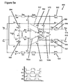
- Figure 5a to 5c Such an embodiment is shown as Figure 5a to 5c .
- Figure 5b shows the SHA 500 in the sample/track phase of operation
- Figure 5c shows the SHA 500 in the hold phase of operation. Components that have been described with earlier embodiments will not be described again with reference to Figures 5a to 5c .
- the OTA 502 is switched into a unity gain configuration and the output tracks the input during the track phase, when ⁇ 1 is high.
- the OTA 502 is configured as a normal two-stage Miller OTA 502, having a first sub-stage 502a, and a second sub-stage 502b.
- the Miller capacitance C mp 560 and optional compensation resistor R mp 564 are connected between the positive output of the first sub-stage 502a (node g) of the OTA 502 and the negative output pin of the second sub-stage 502b (node c) of the OTA 502 through switch S pcfbp 520.
- Miller capacitance C mn 562 and R mn 566 are connected between the negative output of the first sub-stage 502a (node h) of the OTA 502 and the positive output pin of the second sub-stage 502b (node f) of the OTA 502 through switch S pcfbn 522.
- Miller capacitances C mp 560 and C mn 562 and optional compensation resistors R mp 564 and R mn 566 are actually part of the Miller OTA 502, and are shown outside the OTA 502 in Figure 5 for ease of illustration and understanding. It will also be appreciated that switches S at1p 568. S stin 570 and S st1pn 572 are not part of a standard. Miller OTA and can be required/used to obtain the desired operation.
- the amplifier sub-stages 502a, 502b of the OTA 502 are connected to each other to operate like a two-stage Miller OTA 502 in the sample phase of operation. To compensate for the inversion of the input signal the differential input signals are crosscoupled.
- the instantaneous signals on the Miller capacitors C mp 560 and C mn 562 are sampled when the respective switches S st1p 568 and S st1n 570 are opened and both amplifier sub-stages 502a, 502b of the OTA 502 are disconnected from each other. Only the first amplifier sub-stage 502a of the OTA 502 is used during the hold phase.
- the second amplifier sub-stage 502b can still be active however, and to prevent/reduce any noise being coupled into the now floating input of the second sub-stage 502b, and therefore being amplified by the second sub-stage 502b, the inputs to the second sub-stage 502b can be short circuited by closing switch S st1pn 572.
- the transfer from the OTA 502 input to the output of the SHA 500 becomes non-inverting.
- the positive plate of the sample capacitor C sp 504 is connected to the negative input of the OTA 502
- the positive plate of the sample capacitor C sn 506 is connected to the positive input of the OTA 502.
- An advantage of using a Miller topology to implement CLS is that there is no/reduced additional loading of the OTA during the pre-charge phase. Also, additional couple capacitors are not required. Another advantage is that during the hold phase, only the first stage of the OTA can be active (the second stage being effectively de-activated), and a single stage OTA can achieve a larger bandwidth than a two stage OTA.
- One or more embodiments can relate to an integrated circuit (IC) comprising a sample-and-hold amplifier (SHA) as disclosed herein.
- the SHA may be part of an analogue-to-digital converter (ADC), which may be provided on an IC.
- ADC analogue-to-digital converter
- Embodiments of the invention can be particularly advantageous as part of a 14 bit ADC with a sample rate that is greater than 25D mega samples per second.
Abstract
Description
- The present disclosure relates to the field of sample-and-hold amplifiers, and particularly, although not exclusively, sample-and-hold amplifiers having a hold phase of operation and a sample phase of operation that can be used with time-interleaved analogue to digital converters.
- There is a trend towards ever higher sample-rates for high-resolution analogue to digital converters (ADCs). Time interleaving is a common technique to increase the sample rate, although time interleaving of the front-end sample-and-hold amplifier (SHA) may not be practical for high-resolution ADCs due to stringent timing alignment requirements. "A CMOS 33-mW 100-MHz 80-dB SFDR Sample-and-Hold Amplifier" by C-C Hsu and Wu J-T (VLSI Circuits Symp. Dig., pages 263-264, 2003) discloses a high-speed high-resolution sample-and-hold amplifier (SHA).
- "A CMOS 15-bit 125-MS/s Time-lnterleaved ADC With Digital Background Calibration" by Z-M Lee, C-Y Wang, and J-T Wu. (IEEE Journal of Solid-State Circuits, 42:2149-2160, 2007) discloses a two-channel time-interleaved pipelined ADC.
- "An Over-60dB True Rail-fo-Rail Performance Using Correlated Level Shifting and an Opamp With Only 30 dB Loop Gain" by B.R. Gregoire and U.-K. Moon (IEEE Journal of Solid-State Circuits, 43;2620-2630, 2008) discloses correlated level shifting (CLS).
- The listing or discussion of a prior-published document or any background in the specification should not necessarily be taken as an acknowledgement that the document or background is part of the state of the art or is common general knowledge.
- According to a first aspect of the invention, there is provided a sample-and-hold amplifier having a sample phase of operation and a hold phase of operation, the sample-and-hold amplifier comprising:
- one or more sampling components configured to sample input signals during the sample phase of operation, and provide sampled input signals during the hold phase of operation; and
- an amplifier configured to pre-charge the output of the sample-and-hold amplifier during the sample phase of operation, and buffer the sampled input signal during the hold phase of operation.
- Utilising the amplifier to pre-charge the output, for example by setting the voltage at the output of the sample,and-hold amplifier at a level that is likely to be closer to the desired output level, can provide an efficient sample-and-hold amplifier- Prior art sample-and-hold amplifiers that use auxiliary/additional amplifiers/buffers to pre-charge the output can consume more power than embodiments of the invention.
- The one or more sampling components may be one or more capacitors that are configured to be charged by the input signals during the sample phase of operation, and connected across the amplifier during the hold phase of operation to provide the buffered/sampled input signals.
- The amplifier may be configured to pre-charge the output of the sample-and-hold amplifier by coupling the input signals of the sample-and-hold amplifier to the inputs of the amplifier, and coupling the inputs of the amplifier to the outputs of the sample-and-hold amplifier. In this way, the instantaneous value at the input to the sample-and-hofd amplifier can be passed to the output of the sample-and-hold amplifier whilst the input is being sampled, and this instantaneous value can be closer to the desired output level than the level that was recorded during the previous sampling operation.
- The sample-and-hold amplifier may comprise a plurality of switches that are switchable in order to set the phase of operation of the sample-and-hold amplifier. It will be appreciated that numerous different configurations of switches can be provided that enable the sample-and-hold amplifier to operate as disclosed herein.
- The sample-and-hold amplifier may further comprise a feedback network between the inputs of the amplifier, the outputs of the amplifier, and the inputs of the sample-and-hold amplifier. Through operation of associated switches, the feedback network and the amplifier can provide a unity gain amplifie/lbuffer between the Inputs and outputs of the sample-and-hold amplifier during the sample phase of operation.
- The feedback network can comprise passive components, and in some embodiments only passive components. The passive components can be resistors and/or capacitors and/or switches and/or coils/inductors, and may not include active components such as amplifiers that consume power.
- The amplifier may be an operational transconductance amplifier or an operational amplifier.
- The amplifier may be a Miller amplifier having a first sub-stage and a second sub-stage. The amplifier may also comprise a first Miller capacitance associated with a first (negative) output of the Miller amplifier, and a second Miller capacitance associated with a second (positive) output of the Miller amplifier. The second sub-stage may be disconnected/decoupled/ bypassed during the hold phase of operation.
- The Miller capacitances may be configured such that the output of the sample-and-hold amplifier during the sample phase of operation is pre-charged as well as the Miller capacitances themselves. The Miller capacitances can then be used as level shift capacitors during the hold phase of operation of the sample-and-hold amplifier (SHA) to implement correlated level shifting (CLS) without requiring any additional components.
- The first and second sub-stages may be used in series during the sample mode of operation.
- The feedback factor of the amplifier may be 0.5 during the sample phase of operation. The feedback factor of the amplifier may be 1 during the hold phase of operation.
- According to a further aspect of the invention, there is provided a method of operating a sample-and-hold amplifier, the sample-and-hold amplifier comprising an amplifier, the method comprising:
- sampling input signals during a sample phase of operation;
- providing sampled input signals during a hold phase of operation; and
- using the amplifier to:
- pre-charge the output of the sample-and-hold amplifier during the sample phase of operation; and
- buffer the sampled input signal during the hold phase of operation.
- According to a further aspect of the invention, there is provided an analogue to digital converter comprising any sample-and-hold amplifier disclosed herein.
- According to a further aspect of the invention, there is provided an integrated circuit comprising any sample-and-hold amplifier disclosed herein, or any analogue to digital converter disclosed herein.
- According to a further aspect of the invention, there is provided a computer program, which when run on a computer, causes the computer to configure any apparatus, including a sample-and-hold amplifier, analogue to digital converter, circuit, system, or device disclosed herein or perform any method disclosed herein. The computer program may be a software implementation, and the computer may be considered as any appropriate hardware, including a digital signal processor, a microcontroller, and an implementation in read only memory (ROM), erasable programmable read only memory (EPROM) or electronically erasable programmable read only memory (EEPROM), as non-limiting examples. The software may be an assembly program.
- The computer program may be provided on a computer readable medium such as a disc or a memory device, or may be embodied as a transient signal. Such a transient signal may be a network download, including an internet download.
- A description is now given, by way of example only, with reference to the accompanying drawings, in which:
-
Figure 1 illustrates the architecture of a time-interleaved ADC; -
Figure 2 illustrates a prior art sample and hold amplifier -
Figures 3a to 3c illustrate a prior art buffered pre-charge sample-and-hold amplifier, -
Figures 4a to 4c illustrate a sample-and-hold amplifier according to an embodiment of the invention; -
Figures 5a to 5c illustrate a sample-and-hold amplifier according to another embodiment of the invention; and -
Figure 6 illustrates an OTA that can be used with embodiments of the invention. - One or more embodiments described herein relate to a sample-and-hold amplifier that operates according to a sample phase of operation and a hold phase of operation. The sample-and-hold amplifier includes an amplifier (such as an operational transconductance amplifier (OTA)) which can be used to buffer an input signal during the hold phase of operation in a conventional way, and can also be used to "pre-charge" the output of the sample-and-hold amplifier during the sample phase of operation.. Such embodiments can avoid the requirement for additional buffers to pre-charge the output during the sample phase of operation by utilising the OTA that would otherwise not be used during the sample phase of operation. This can lead to a more efficient sample-and-hald amplifier, as fewer components may be required and/or power consumption of the sample-and-hold amplifier can be reduced.
- In some embodiments, a Miller topology amplifier can be used as part of the sample-and-hold amplifier, and the amplifier can be used to pre-charge the output during the sample phase and the Miller capacitance can be used to implement correlated level shifting (CLS) in the hold phase.
-
Figure 1 illustrates the architecture of a time-interteaved analogue to digital converter (ADC) 100. In this example, the ADC 100 consists of two back-end ADC slices 112. - The ADC 100 receives an
analogue input signal 102 which is provided to a sample-and-hold amplifier (SHA) 106. The SHA 100 is operated according to a requiredsampling frequency F s 108, and the output of theSHA 106 is coupled to one of the interleavedADC slices 112 by aswitching component 110. Theswitching component 110 is also operated according to theswitching frequency F s 108. By providing a plurality of interleavedADC slices 112, theADC slices 112 can operate at a frequency that is less than the required sampling frequency, and in this example theADC slices 112 operate at Fs/2 114. The outputs of theADC slices 112 are then multiplexed by switchingcomponent 116, operating at thesampling frequency F s 108, to provide thedigital output signal 104. - It will be appreciated that although the frequency of operation of the
ADC slices 112 has been reduced, the SHA 106 still has to operate at the fullsample rate F s 108. Therefore, the speed of theSHA 106 can limit the overall ADC speed. -
Figure 2 illustrates schematically an example of a prior art sample-and-hold amplifier (SHA) 200. TheSHA 200 includes an operational transconductance amplifier (OTA) 202, a firstsampling capacitor C sp 204 that is used to sample the positive input to theSHA 200, and a secondsampling capacitor C sn 206 that is used to sample the negative input voltage. TheSHA 200 can operate according to a first and second phase of operation according to the state of a number of switches in theSHA 200 that are operated by clock signals ϕ1 and ϕ2. Further details of the operation of such anSHA 200 will be appreciated from the following description ofFigures 3a to 3c that illustrate a similar prior art example. - As is known in the art, the demands on the
OTA 202 can be relaxed by pre-charging the output with auxiliary buffers, and such an example will be described with reference toFigures 3a to 3c . -
Figure 3a illustrates a buffered pre-charge sample-and-hold amplifier (SHA) 300 and a corresponding timing diagram 301 showing the inter-relation of the different phases of operation. Each switch inFigure 3a is shown associated with the clock signal (ϕ1, ϕ1e. ϕ2) with which it is operated, and the state of the switches defines the phase of operation.Figure 3b illustrates theSHA 300 ofFigure 3a in a sample phase of operation, that is when ϕ1 and ϕ1e are high (and the associated switches are closed), and ϕ2 is low (and the associated switches are open).Figure 3c illustrates theSHA 300 ofFigure 3a in a hold phase of operation, that is when ϕ2 is high, and ϕ1 and ϕ1e are low. - It can be seen that the
SHA 300 ofFigure 3 includes two auxiliary/additional amplifiers 305, 310 that can be directly connected between theinputs SHA 300 and theoutputs SHA 300. Theadditional amplifiers inputs outputs switches outputs SHA 300 is more accurately sampling the signal level at theinput - A more detailed description of the operation of the
SHA 300 with relation toFigures 3a to 3c will now follow. -
Figure 3a includes a timing diagram 301 that illustrates the sample-and-hold phase of operation of theSHA 300. TheSHA 300 is operating in a sample mode of operation when the clock signal ϕ1 is high and the dock signal ϕ2 is low. A third clock signal, ϕ1e, generally corresponds to the clock signal ϕ1, although is configured such that it transitions from a high value to a low value shortly before the ϕ1 clock signal transitions from a high value to a low value. - The third clock signal, ϕ1e, is applied to the following switches:
- switch 326 between the
reference input voltage 324 and the positive input of theOTA 302; - switch 328 between the
reference input voltage 324 and the negative input of theOTA 302; and - switch 327 between the negative input of the
OTA 302 and the positive input of theOTA 302. - It will be appreciated that
switch 327 is optional in some embodiments, as the SHA may be able to function withoutswitch 327. - With these switches (326, 327, 328) there is only a small voltage swing at the terminals of the switches (326, 327, 328), which is in contrast to the voltage swing at the terminals of
switches negative input voltages switches switches switches -
Figure 3b illustrates theSHA 300 ofFigure 3a in the sample phase of operation, with the switches that are associated with the clock signals ϕ1 and ϕ1e closed, and the switches that are associated with the clock signal ϕ2 open.Figure 3c illustrates theSHA 300 ofFigure 3a in the hold phase of operation, with the switches associated with the clock signal ϕ2 closed, and the switches associated with the clock signals ϕ1 and ϕ1e open. - The
SHA 300 receives apositive input voltage 312, anegative input voltage 314 and areference input voltage 324. In some examples, thereference input voltage 324 may be ground. - When the clock signal ϕ1e goes high, and the
SHA 300 enters the sample mode of operation, the twoswitches reference input voltage 324 and the positive plates of thesampling capacitors switches inputs sampling capacitors negative inputs sample capacitors - Also during the sample phase of operation, as illustrated in
Figure 3b , theadditional amplifiers respective inputs outputs SHA 300 as theswitches OTA 302 are pre-charged to an approximate level of the intended output. - In the hold phase of operation, as shown in
Figure 3c , theswitches sampling capacitors outputs sampling capacitors OTA 302 form a unity gain buffer that buffers the sampled input signals. - As the outputs of the
OTA 302 have been pre-charged/pre-set to approximate output levels during the sample phase, when theOTA 302 is changed to the hold phase of operation, the output of theOTA 302 only needs to be adjusted by a pre-charge error instead of the difference between the value on the sample capacitor and the previous output signal of theOTA 302 that is still stored on the load capacitance. That is, the amount that the output signal of theOTA 302 has to change when entering a hold mode of operation can be reduced. The load capacitance is the sum of theOTA 302 output capacitance, sample capacitance of an ADC slice with which theSHA 300 is associated, and any parasitic capacitances. - The
additional buffers SHA 300 such that a high input bandwidth can be realised. The additional amplifiers/buffers additional amplifiers - The
capacitors C tp 338 and Cin 340 shown inFigure 3 are optional, and are connected between the outputs of theOTA 302 and theoutputs SHA 300. Such capacitors can implement a technique known as correlated level shifting (CLS) such that during the sample phase of operation as illustrated inFigure 3b , the level-shift capacitors 338, 340 are also pre-charged such that the output swing of theOTA 302 when entering the hold phase of operation can be reduced. - Incorporation of the
optional capacitors 338, 340 can introduce an additional linearity requirement for theadditional amplifiers optional capacitors 338, 340 that are required to implement CLS are an additional load for theadditional amplifiers - The requirement for linearity of the
additional amplifiers open loop OTA 302 gain. Therefore, a simple open-loop source-follower buffer, or a single stage OTA with unity feedback, may be used. For correct operation, without severe distortion, the input transistors) of theadditional buffers - For noise-limited ADCs, a large input signal swing is beneficial to realise an energy efficient converter. In order to be able to handle a large input signal swing, the
amplifiers Figure 3a will consume a large amount of power, and therefore will reduce the efficiency of the SHA. The input transistor(s) in the buffers also need to be kept in saturation to prevent severe distortion, and when a simple open-loop source-follawer buffer, or single stage OTA, is used as an additional amplifier this requirement can limit the SHA and thus the ADC input signal swing. - A feedback network can be provided across an OTA used as an auxiliary buffer in order to realise a unity gain closed loop transfer function, and in this way the voltage swing across the input transistors can be reduced. The voltage at the input transistors is equal to the OTA output voltage swing divided by the open loop gain of the OTA. A single stage OTA may not be able to achieve the required gain, and therefore a two-stage OTA may be required in order to reduce the swing at the input transistors, and this can consume more power still.
- One or more embodiments described herein can relate to an SHA architecture whereby the main OTA itself is used as a buffer/amplifier with a feedback network to pre-charge the output during a sample phase of operation. In the prior art, the main OTA (302 in
Figure 3a ) is not normally used during the sample phase of operation, although it will still consume power. Therefore, it has been identified that it is possible to reuse the main OTA during the sample phase of operation in order to reduce the overall SHA power consumption. Reusing the main OTA to pre-charge the SHA output renders an auxiliary/additional buffer/amplifier redundant. Furthermore, using a feedback network across the OTA to realise a unity gain buffer can ensure that the signal swing handling capabilities of the SHA is not limited. - An example of a self-buffered pre-charge SHA is illustrated in
Figures 4a to 4c .Figure 4b illustrates theSHA 400 ofFigure 4a with the switches arranged according to the sample phase of operation, andFigure 4c shows theSHA 400 with the switches arranged according to the hold phase of operation. Those components ofFigures 4a to 4c that have already been described and illustrated with reference toFigures 3a to 3c will not necessarily be described again here. - During the sample phase of operation as illustrated in
Figure 4b , the clock signal ϕ1 is high, and theOTA 402 is in a unity gain configuration such that the output tracks the input TheOTA 402 may not be able to handle a large signal swing at its inputs, and therefore feedback networks are used to keep the levels at the inputs at victual ground, and therefore there will only be a small voltage swing at the input due to the finite gain of theOTA 402. The feedback network consists of two branches, each with two impedances. The first feedback branch consists of Spcip switch 452, Zpcip impedance 440,switch 444, Zpcfbp impedance 442 and Spcfbp switch 420. The Spcip switch 452 is connected between thenegative input pin 414 and a first terminal of the Zpcip impedance 440. The second terminal of the Zpcip impedance 440 is connected to a first terminal of the Zpcfbb impedance 442, and the second terminal of the Zpcfbp impedance 442 is connected to thepositive output pin 416 by the Spcfbp switch 420. Anotherswitch 444 is connected between the positive input of theOTA 402 and the junction between the Zpcip impedance 440 and theZ pcfbp 442 impedance. Theswitches switch 444 is operated in accordance with the ϕ1e clock signal. - As can be seen in
Figure 4b , the second feedback branch comprises similar components and is similarly connected to thepositive input pin 412, thenegative output pin 418 and the negative input of theOTA 402. - In addition, further switches Scp 456 and
S cn 458 are connected between the positive plates of thesampling capacitors OTA 402 to decouple the signal on the inputs of theOTA 402 form the signal on the positive plates of the capacitors. - To have unity gain during the pre-charging/sample phase of operation, both impedances in each branch of the feedback network should have the same value. That is,
Z pcin 446 should equalZ pcfbn 448, andZ pcip 440 should equalZ pcfbp 442. - Passive components (such as resistors and capacitors) can be used as the
impedances - When resistors are used as the impedances, the input source would have to deliver a DC current, and the input signals to the
SHA 400 would be reduced by the resistive voltage division of the feedback branches. Therefore, the impedance of these resistors should be large, for example several kilo ohms. The switches in the feedback branches (Spcip and Spcfbp; and Spcin and Spcfbn) cannot be used to realise the required impedance. The distortion introduced by these switches, which would also be seen at the input, would reduce the linearity of the signal on the sample capacitor. Also, large feedback resistor values, in combination with the input capacitance of theOTA 402, may lead to stability problems. - To improve the performance, capacitors can be used instead of resistors as the impedance components (Zpcin, Zpcfbn, Zpcip, Zpcfbp) in the feedback network. For proper operation, the initial conditions of each of the capacitors should be the same at the start of each sample/track phase of operation. To provide such equal initial conditions, the capacitors in the feedback network can be reset during the hold phase of operation. It will be appreciated by the skilled person that additional switches can be added to the
SHA 400 ofFigure 4a in order to provide this functionality as is well known in the art For example, including an additional switch across the capacitors, or including switches between nodes a, b and c and Vrefmid, and between nodes d,e and f and Vrefmid can provide the required initial conditions. - When the
OTA 402 is used as a unity gain buffer during the track/sample phase of operation, theOTA 402 inverts the input signal- In the hold phase of operation however, the signal on the sample capacitors Csp and Csn is not inverted. To compensate for this, the input signal can be inverted during the track/sample phase of operation by interchanging the connection of the differential input signal. The input signal received at the positiveinput terminal V inp 412 is connected to node d ofZ pcin 446 and input signal received at the negativeinput terminal V inn 414 is connected to node a ofZ pcip 440 during the track/sample phase of operation. - During the track/sample phase of operation, the feedback factor of the
OTA 402 is ideally 0.5, and during the hold phase of operation, the feedback factor of theOTA 402 is 1. To obtain the same closed-loop gain bandwidth (GBW) during the track/sample phase theOTA 402 GBW can be increased during this phase while maintaining stability. - In examples where a
Miller OTA 402 is used, then the gain-bandwidth (GBW) of the OTA can be made larger while maintaining stability during the track phase by dividing the - Miller capacitor into two parts in parallel. An example of such an OTA is shown in
Figure 6 . The Miller capacitor can then be made smaller during the track phase by switching off - one part The part of the Miller capacitor that is switched off may need to be pre-charged to ensure that the output is not influenced too much when switching to the hold phase of the SHA. During this pre-charging, the bottom plate of the Miller capacitor, which is connected to the output of the first amplifier stage of the OTA during the hold phase, should be connected to the common-mode output reference voltage of the first amplifier stage of the OTA. - In alternative embodiments, the first amplifier stage of the OTA can be split into two smaller stages connected in parallel- In such embodiments, both amplifier stages are used during the track phase to achieve a high transconductance (gm), and one amplifier stage is switched off during the hold phase to lower the transconductance (gm).
- It will be appreciated that the circuits described above provide non-limiting examples of how the gain-bandwidth (GBW) of on OTA can be changed, and that alternative implementation may be known to those skilled in the art.
- In examples where the main OTA is a two-stage Miller architecture, the associated Miller capacitance can be reused to implement correlated level shifting (CLS). The Miller capacitances can then be used as level shift capacitances during the hold phase. Such an embodiment is shown as
Figure 5a to 5c .Figure 5b shows theSHA 500 in the sample/track phase of operation, andFigure 5c shows theSHA 500 in the hold phase of operation. Components that have been described with earlier embodiments will not be described again with reference toFigures 5a to 5c . - As shown in
Figure 5b , theOTA 502 is switched into a unity gain configuration and the output tracks the input during the track phase, when ϕ1 is high. - The
OTA 502 is configured as a normal two-stage Miller OTA 502, having afirst sub-stage 502a, and asecond sub-stage 502b. TheMiller capacitance C mp 560 and optionalcompensation resistor R mp 564 are connected between the positive output of the first sub-stage 502a (node g) of theOTA 502 and the negative output pin of thesecond sub-stage 502b (node c) of theOTA 502 throughswitch S pcfbp 520. CorrespondinglyMiller capacitance C mn 562 andR mn 566 are connected between the negative output of the first sub-stage 502a (node h) of theOTA 502 and the positive output pin of thesecond sub-stage 502b (node f) of theOTA 502 throughswitch S pcfbn 522. - It will be appreciated that the Miller capacitances
C mp 560 andC mn 562 and optional compensation resistors Rmp 564 andR mn 566 are actually part of theMiller OTA 502, and are shown outside theOTA 502 inFigure 5 for ease of illustration and understanding. It will also be appreciated that switchesS at1p 568.S stin 570 andS st1pn 572 are not part of a standard. Miller OTA and can be required/used to obtain the desired operation. - The amplifier sub-stages 502a, 502b of the
OTA 502 are connected to each other to operate like a two-stage Miller OTA 502 in the sample phase of operation. To compensate for the inversion of the input signal the differential input signals are crosscoupled. When theSHA 500 is in the sample phase of operation, and the clock signal ϕ1e goes low, the instantaneous signals on the Miller capacitors Cmp 560 andC mn 562 are sampled when the respective switches Sst1p 568 andS st1n 570 are opened and both amplifier sub-stages 502a, 502b of theOTA 502 are disconnected from each other. Only thefirst amplifier sub-stage 502a of theOTA 502 is used during the hold phase. Thesecond amplifier sub-stage 502b can still be active however, and to prevent/reduce any noise being coupled into the now floating input of thesecond sub-stage 502b, and therefore being amplified by thesecond sub-stage 502b, the inputs to thesecond sub-stage 502b can be short circuited by closingswitch S st1pn 572. - As the
second amplifier sub-stage 502b is decoupled during the hold phase of operation, the transfer from theOTA 502 input to the output of theSHA 500 becomes non-inverting. To have an overall negative feedback the positive plate of thesample capacitor C sp 504 is connected to the negative input of theOTA 502, and the positive plate of thesample capacitor C sn 506 is connected to the positive input of theOTA 502. - In the same way as described above, two eq ual impedances having the same values can be used for the feedback network.
- An advantage of using a Miller topology to implement CLS is that there is no/reduced additional loading of the OTA during the pre-charge phase. Also, additional couple capacitors are not required. Another advantage is that during the hold phase, only the first stage of the OTA can be active (the second stage being effectively de-activated), and a single stage OTA can achieve a larger bandwidth than a two stage OTA.
- One or more embodiments can relate to an integrated circuit (IC) comprising a sample-and-hold amplifier (SHA) as disclosed herein. The SHA may be part of an analogue-to-digital converter (ADC), which may be provided on an IC. Embodiments of the invention can be particularly advantageous as part of a 14 bit ADC with a sample rate that is greater than 25D mega samples per second.
Claims (15)
- A sample-and-hold amplifier (400) having a sample phase of operation and a hold phase of operation, the sample-and-hold amplifier comprising:one or more sampling components (404, 406) configured to sample input signals during the sample phase of operation, and provide sampled input signals during the hold phase of operation; andan amplifier (402) configured to pre-charge the output (416, 418) of the sample-and-hold amplifier (400) during the sample phase of operation, and buffer the sampled input signal during the hold phase of operation.
- The sample-and-hold amplifier (400) of claim 1, wherein the one or more sampling components are one or more capacitors (404, 406) that are configured to be charged by the input signals during the sample phase of operation, and connected across the amplifier (402) during the hold phase of operation to provide the sampled input signals.
- The sample-and-hold amplifier (400) of claim 1 or claim 2, wherein the amplifier (402) is configured to pre-charge the output of the sample-and-hold amplifier (400) during the sample phase of operation by coupling the input signals of the sample-and-hold amplifier (400) to the inputs of the amplifier (402), and coupling the inputs of the amplifier (402) to the outputs of the sample-and-hold amplifier (400).
- The sample-and-hold amplifier (400) of any preceding claim, wherein the sample-and-hold amplifier (400) comprises a plurality of switches that are switchable in order to set the phase of operation of the sample-and-hold amplifier (400).
- The sample-and-hold amplifier (400) of any preceding claim, further comprising a feedback network between the inputs of the amplifier (402), the outputs of the amplifier (402), and the inputs of the sample-and-hold amplifier (400).
- The sample-and-hold amplifier (400) of claim 5, wherein the feedback network and the amplifiers (402) provide a unity gain amplifier between the inputs and outputs of the sample-and-hold amplifier (400) during the sample phase of operation.
- The sample-and-hold amplifier (400) of claim 5 or claim 6, wherein the feedback network comprises passive components.
- The sample-and-hold amplifier (400) of any preceding claim, wherein the amplifier (402) is an operational transconductance amplifiers or an operational amplifier.
- The sample-and-hold amplifier (500) of any preceding claim, wherein the amplifier is a Miller amplifier (502) having a first sub-stage (502a) and a second sub-stage (502b), and first and second Miller capacitances (560, 562), wherein the Miller capacitances (560. 562) are configured to allow the Miller amplifier (502) to pre-charge the output of the sample-and-hold amplifier (500) during the sample phase of operation, and also the Miller capacitances (560, 562) are configured to be pre-charged to the output voltage of the sample-and-hold amplifier (500) during the sample phase of operation, and wherein the second sub-stage is configured to be disconnected during the hold phase of operation.
- The sample-and-hold amplifier (500) of claim 9, wherein the first and second Miller capacitances (560, 562) are configured to implement correlated level shifting during the hold phase of operation.
- The sample-and-hold amplifier (500) of claim 9 or claim 10, wherein the first and second sub-stages (502a, 502b) are configured in series during the sample mode of operation.
- The sample-and-hold amplifier (500) of claim 9 or claim 10 or claim 19, wherein the Miller capacitances (560, 562) are configured as level shift capacitors during the hold phase of operation.
- An analogue to digital converter comprising the sample-and-hold amplifier (400) according to any one of claims 1 to 12.
- A method of operating a sample-and-hold amplifier (400), the sample-and-hold amplifier (400) comprising an amplifier (402), the method comprising:sampling input signals during a sample phase of operation;providing sampled input signals during a hold phase of operation; andusing the amplifier (402) to:pre-charge the output of the sample-and-hold amplifier (400) during the sample phase of operation; andbuffer the sampled input signal during the hold phase of operation.
- A computer program, which when run on a computer, causes the computer to configure the sample,and-hold amplifiers of any one of claims 1 to 12, the analogue to digital converter of claim 13. or perform the method of claim 14.
Priority Applications (3)
| Application Number | Priority Date | Filing Date | Title |
|---|---|---|---|
| EP10250528.6A EP2367285B1 (en) | 2010-03-19 | 2010-03-19 | A sample-and-hold amplifier |
| US13/050,541 US8390372B2 (en) | 2010-03-19 | 2011-03-17 | Sample-and-hold amplifier |
| CN201110068892.5A CN102195652B (en) | 2010-03-19 | 2011-03-18 | A sample-and-hold amplifier |
Applications Claiming Priority (1)
| Application Number | Priority Date | Filing Date | Title |
|---|---|---|---|
| EP10250528.6A EP2367285B1 (en) | 2010-03-19 | 2010-03-19 | A sample-and-hold amplifier |
Publications (2)
| Publication Number | Publication Date |
|---|---|
| EP2367285A1 true EP2367285A1 (en) | 2011-09-21 |
| EP2367285B1 EP2367285B1 (en) | 2016-05-11 |
Family
ID=42562845
Family Applications (1)
| Application Number | Title | Priority Date | Filing Date |
|---|---|---|---|
| EP10250528.6A Not-in-force EP2367285B1 (en) | 2010-03-19 | 2010-03-19 | A sample-and-hold amplifier |
Country Status (3)
| Country | Link |
|---|---|
| US (1) | US8390372B2 (en) |
| EP (1) | EP2367285B1 (en) |
| CN (1) | CN102195652B (en) |
Families Citing this family (26)
| Publication number | Priority date | Publication date | Assignee | Title |
|---|---|---|---|---|
| US8698555B2 (en) * | 2010-11-19 | 2014-04-15 | Marvell World Trade Ltd. | Low distortion variable gain amplifier (VGA) |
| US9143092B2 (en) | 2011-12-14 | 2015-09-22 | Maxim Integrated Products, Inc. | Fully capacitive coupled input choppers |
| US20130154740A1 (en) * | 2011-12-16 | 2013-06-20 | Qualcomm Incorporated | Techniques for pga linearity |
| JP2013207697A (en) * | 2012-03-29 | 2013-10-07 | Asahi Kasei Electronics Co Ltd | Sample hold circuit |
| CN103427840B (en) * | 2012-05-25 | 2016-08-17 | 联发科技(新加坡)私人有限公司 | Signal processing circuit |
| US8704691B2 (en) | 2012-09-07 | 2014-04-22 | Lsi Corporation | Track-and-hold circuit for analog-to-digital converter with switched capacitor coupling of amplifier stage |
| JP6156752B2 (en) | 2012-11-30 | 2017-07-05 | パナソニックIpマネジメント株式会社 | Switched capacitor circuit and driving method thereof |
| CN103997306B (en) * | 2013-02-16 | 2018-07-27 | 马克西姆综合产品公司 | The condenser coupling amplifier of fast and stable |
| WO2015004863A1 (en) | 2013-07-09 | 2015-01-15 | パナソニック株式会社 | Switched capacitor circuit and method for driving same |
| US9143100B2 (en) * | 2013-09-30 | 2015-09-22 | Texas Instruments Incorporated | Method and circuitry for multi-stage amplification |
| US9224499B2 (en) | 2014-02-07 | 2015-12-29 | Infineon Technologies Ag | Pre-charge sample-and-hold circuit and method for pre-charging a sample-and-hold circuit |
| CN103905750B (en) * | 2014-03-17 | 2017-05-03 | 中国科学院半导体研究所 | Simulation reading preprocessing circuit used for solid-state image sensor |
| CN104469201B (en) * | 2014-12-29 | 2017-05-17 | 中国科学院半导体研究所 | Analog reading preprocessing circuit for CMOS image sensor and control method thereof |
| CN106160671B (en) * | 2015-04-10 | 2019-03-15 | 无锡华润上华科技有限公司 | Signal amplification circuit |
| US9960782B2 (en) * | 2015-09-11 | 2018-05-01 | Texas Instruments Incorporated | Precharge switch-capacitor circuit and method |
| US9813035B2 (en) * | 2015-11-02 | 2017-11-07 | Analog Devices, Inc. | Gain enhancement using advanced correlated level shifting |
| US9503115B1 (en) * | 2016-02-19 | 2016-11-22 | Xilinx, Inc. | Circuit for and method of implementing a time-interleaved analog-to-digital converter |
| JP2017216669A (en) * | 2016-05-26 | 2017-12-07 | パナソニックIpマネジメント株式会社 | Amplifier circuit and pulse wave measurement apparatus |
| US10158334B2 (en) | 2016-09-09 | 2018-12-18 | Analog Devices Global | Fast settling capacitive gain amplifier circuit |
| US9667234B1 (en) | 2016-11-11 | 2017-05-30 | Teledyne Scientific & Imaging, Llc | Slew-rate enhanced energy efficient source follower circuit |
| EP3432470B1 (en) * | 2017-07-20 | 2020-12-23 | ams AG | A circuit arrangement and a method for operating a circuit arrangement |
| US10804851B2 (en) * | 2018-04-04 | 2020-10-13 | Maxim Integrated Products, Inc. | Systems and methods for a current sense amplifier comprising a sample and hold circuit |
| US10809792B2 (en) * | 2018-08-16 | 2020-10-20 | Analog Devices, Inc. | Correlated double sampling amplifier for low power |
| CN113328746A (en) * | 2020-02-28 | 2021-08-31 | 瑞昱半导体股份有限公司 | Sample-and-hold amplifying circuit |
| US11211904B1 (en) | 2020-06-30 | 2021-12-28 | Nxp B.V. | Switched-capacitor amplifier circuit |
| TWI792840B (en) * | 2022-01-07 | 2023-02-11 | 瑞昱半導體股份有限公司 | Usb chip and operation method thereof |
Citations (3)
| Publication number | Priority date | Publication date | Assignee | Title |
|---|---|---|---|---|
| US5914638A (en) * | 1997-06-06 | 1999-06-22 | Omnivision Technologies, Inc. | Method and apparatus for adjusting the common-mode output voltage of a sample-and-hold amplifier |
| WO2002007306A1 (en) * | 2000-07-18 | 2002-01-24 | Robert Bosch Gmbh | Amplifier circuit |
| US20070001757A1 (en) * | 2005-06-30 | 2007-01-04 | Josefsson Olafur M | Switched capacitor system with and method for output glitch reduction |
Family Cites Families (5)
| Publication number | Priority date | Publication date | Assignee | Title |
|---|---|---|---|---|
| ATE120587T1 (en) * | 1987-11-19 | 1995-04-15 | Siemens Ag | ANALOG-DIGITAL CONVERTER. |
| US5410270A (en) * | 1994-02-14 | 1995-04-25 | Motorola, Inc. | Differential amplifier circuit having offset cancellation and method therefor |
| US6577185B1 (en) * | 2001-03-19 | 2003-06-10 | Cisco Systems Wireless Networking (Australia) Pty. Limited | Multi-stage operational amplifier for interstage amplification in a pipeline analog-to-digital converter |
| CN101217282A (en) * | 2008-01-11 | 2008-07-09 | 复旦大学 | An A/D converter adopting mixed type dual-layer folding circuit |
| US7663516B1 (en) * | 2008-08-25 | 2010-02-16 | Texas Instruments Incorporated | Scheme for non-linearity correction of residue amplifiers in a pipelined analog-to-digital converter (ADC) |
-
2010
- 2010-03-19 EP EP10250528.6A patent/EP2367285B1/en not_active Not-in-force
-
2011
- 2011-03-17 US US13/050,541 patent/US8390372B2/en not_active Expired - Fee Related
- 2011-03-18 CN CN201110068892.5A patent/CN102195652B/en not_active Expired - Fee Related
Patent Citations (3)
| Publication number | Priority date | Publication date | Assignee | Title |
|---|---|---|---|---|
| US5914638A (en) * | 1997-06-06 | 1999-06-22 | Omnivision Technologies, Inc. | Method and apparatus for adjusting the common-mode output voltage of a sample-and-hold amplifier |
| WO2002007306A1 (en) * | 2000-07-18 | 2002-01-24 | Robert Bosch Gmbh | Amplifier circuit |
| US20070001757A1 (en) * | 2005-06-30 | 2007-01-04 | Josefsson Olafur M | Switched capacitor system with and method for output glitch reduction |
Non-Patent Citations (3)
| Title |
|---|
| B.R. GREGOIRE; U.-K. MOON: "An Over-60dB True Rail-fo-Rail Performance Using Correlated Level Shifting and an Opamp With Only 30 dB Loop Gain", IEEE JOURNAL OF SOLID-STATE CIRCUITS, vol. 43, 2008, pages 2620 - 2T330 |
| C-C HSU; WU J-T, VLSI CIRCUITS SYMP. DIG., 2003, pages 263 - 264 |
| Z-M LEE; C-Y WANG; J-T WU: "A CMOS 15-bit 125-MS/s Time-Interleaved ADC With Digital Background Calibration", IEEE JOURNAL OF SOLID-STATE CIRCUITS, vol. 42, 2007, pages 2149 - 2160 |
Also Published As
| Publication number | Publication date |
|---|---|
| US8390372B2 (en) | 2013-03-05 |
| EP2367285B1 (en) | 2016-05-11 |
| CN102195652A (en) | 2011-09-21 |
| CN102195652B (en) | 2014-07-16 |
| US20120068766A1 (en) | 2012-03-22 |
Similar Documents
| Publication | Publication Date | Title |
|---|---|---|
| EP2367285B1 (en) | A sample-and-hold amplifier | |
| US8791754B2 (en) | Programmable gain amplifier with amplifier common mode sampling system | |
| US8604962B1 (en) | ADC first stage combining both sample-hold and ADC first stage analog-to-digital conversion functions | |
| US7880538B2 (en) | Switched-capacitor amplifier arrangement and method | |
| US7724063B1 (en) | Integrator-based common-mode stabilization technique for pseudo-differential switched-capacitor circuits | |
| US5689201A (en) | Track-and-hold circuit utilizing a negative of the input signal for tracking | |
| US10873336B2 (en) | Track and hold circuits for high speed and interleaved ADCs | |
| US8134401B2 (en) | Systems and methods of low offset switched capacitor comparators | |
| KR20090116721A (en) | Common-mode insensitive sampler | |
| US7920022B2 (en) | Switched capacitor system with and method for output glitch reduction | |
| US7701256B2 (en) | Signal conditioning circuit, a comparator including such a conditioning circuit and a successive approximation converter including such a circuit | |
| US7394309B1 (en) | Balanced offset compensation circuit | |
| TW201310898A (en) | Pseudo differential switched capacitor circuit | |
| US11159170B1 (en) | Differential converter with offset cancelation | |
| US20080180136A1 (en) | Pre-charge sample-and-hold circuit | |
| CN111295837B (en) | Capacitively Coupled Chopper Amplifier | |
| EP0560815B1 (en) | Method for clockfeedthrough error compensation in switched capacitor circuits | |
| EP0729223B1 (en) | Voltage offset compensation circuit | |
| EP2293434B1 (en) | Switched amplifier circuit arrangement and method for switched amplification | |
| US20080094269A1 (en) | Interleaved Track and Hold Circuit | |
| US10855302B2 (en) | Track and hold circuits for high speed and interleaved ADCs | |
| WO2008026228A1 (en) | Differential to single-ended conversion circuit and comparator using the circuit | |
| US9171642B2 (en) | Sampling network | |
| US20120007759A1 (en) | Track-and-hold circuit and a/d converter |
Legal Events
| Date | Code | Title | Description |
|---|---|---|---|
| PUAI | Public reference made under article 153(3) epc to a published international application that has entered the european phase |
Free format text: ORIGINAL CODE: 0009012 |
|
| AK | Designated contracting states |
Kind code of ref document: A1 Designated state(s): AT BE BG CH CY CZ DE DK EE ES FI FR GB GR HR HU IE IS IT LI LT LU LV MC MK MT NL NO PL PT RO SE SI SK SM TR |
|
| AX | Request for extension of the european patent |
Extension state: AL BA ME RS |
|
| 17P | Request for examination filed |
Effective date: 20120321 |
|
| 17Q | First examination report despatched |
Effective date: 20120425 |
|
| GRAP | Despatch of communication of intention to grant a patent |
Free format text: ORIGINAL CODE: EPIDOSNIGR1 |
|
| INTG | Intention to grant announced |
Effective date: 20151127 |
|
| GRAS | Grant fee paid |
Free format text: ORIGINAL CODE: EPIDOSNIGR3 |
|
| GRAA | (expected) grant |
Free format text: ORIGINAL CODE: 0009210 |
|
| AK | Designated contracting states |
Kind code of ref document: B1 Designated state(s): AT BE BG CH CY CZ DE DK EE ES FI FR GB GR HR HU IE IS IT LI LT LU LV MC MK MT NL NO PL PT RO SE SI SK SM TR |
|
| REG | Reference to a national code |
Ref country code: GB Ref legal event code: FG4D |
|
| REG | Reference to a national code |
Ref country code: CH Ref legal event code: EP |
|
| REG | Reference to a national code |
Ref country code: AT Ref legal event code: REF Ref document number: 799366 Country of ref document: AT Kind code of ref document: T Effective date: 20160515 |
|
| REG | Reference to a national code |
Ref country code: IE Ref legal event code: FG4D |
|
| REG | Reference to a national code |
Ref country code: DE Ref legal event code: R096 Ref document number: 602010033232 Country of ref document: DE |
|
| REG | Reference to a national code |
Ref country code: LT Ref legal event code: MG4D |
|
| REG | Reference to a national code |
Ref country code: NL Ref legal event code: MP Effective date: 20160511 |
|
| PG25 | Lapsed in a contracting state [announced via postgrant information from national office to epo] |
Ref country code: LT Free format text: LAPSE BECAUSE OF FAILURE TO SUBMIT A TRANSLATION OF THE DESCRIPTION OR TO PAY THE FEE WITHIN THE PRESCRIBED TIME-LIMIT Effective date: 20160511 Ref country code: FI Free format text: LAPSE BECAUSE OF FAILURE TO SUBMIT A TRANSLATION OF THE DESCRIPTION OR TO PAY THE FEE WITHIN THE PRESCRIBED TIME-LIMIT Effective date: 20160511 Ref country code: NO Free format text: LAPSE BECAUSE OF FAILURE TO SUBMIT A TRANSLATION OF THE DESCRIPTION OR TO PAY THE FEE WITHIN THE PRESCRIBED TIME-LIMIT Effective date: 20160811 Ref country code: NL Free format text: LAPSE BECAUSE OF FAILURE TO SUBMIT A TRANSLATION OF THE DESCRIPTION OR TO PAY THE FEE WITHIN THE PRESCRIBED TIME-LIMIT Effective date: 20160511 |
|
| REG | Reference to a national code |
Ref country code: AT Ref legal event code: MK05 Ref document number: 799366 Country of ref document: AT Kind code of ref document: T Effective date: 20160511 |
|
| PG25 | Lapsed in a contracting state [announced via postgrant information from national office to epo] |
Ref country code: SE Free format text: LAPSE BECAUSE OF FAILURE TO SUBMIT A TRANSLATION OF THE DESCRIPTION OR TO PAY THE FEE WITHIN THE PRESCRIBED TIME-LIMIT Effective date: 20160511 Ref country code: HR Free format text: LAPSE BECAUSE OF FAILURE TO SUBMIT A TRANSLATION OF THE DESCRIPTION OR TO PAY THE FEE WITHIN THE PRESCRIBED TIME-LIMIT Effective date: 20160511 Ref country code: ES Free format text: LAPSE BECAUSE OF FAILURE TO SUBMIT A TRANSLATION OF THE DESCRIPTION OR TO PAY THE FEE WITHIN THE PRESCRIBED TIME-LIMIT Effective date: 20160511 Ref country code: PT Free format text: LAPSE BECAUSE OF FAILURE TO SUBMIT A TRANSLATION OF THE DESCRIPTION OR TO PAY THE FEE WITHIN THE PRESCRIBED TIME-LIMIT Effective date: 20160912 Ref country code: GR Free format text: LAPSE BECAUSE OF FAILURE TO SUBMIT A TRANSLATION OF THE DESCRIPTION OR TO PAY THE FEE WITHIN THE PRESCRIBED TIME-LIMIT Effective date: 20160812 Ref country code: LV Free format text: LAPSE BECAUSE OF FAILURE TO SUBMIT A TRANSLATION OF THE DESCRIPTION OR TO PAY THE FEE WITHIN THE PRESCRIBED TIME-LIMIT Effective date: 20160511 |
|
| PG25 | Lapsed in a contracting state [announced via postgrant information from national office to epo] |
Ref country code: IT Free format text: LAPSE BECAUSE OF FAILURE TO SUBMIT A TRANSLATION OF THE DESCRIPTION OR TO PAY THE FEE WITHIN THE PRESCRIBED TIME-LIMIT Effective date: 20160511 |
|
| PG25 | Lapsed in a contracting state [announced via postgrant information from national office to epo] |
Ref country code: SK Free format text: LAPSE BECAUSE OF FAILURE TO SUBMIT A TRANSLATION OF THE DESCRIPTION OR TO PAY THE FEE WITHIN THE PRESCRIBED TIME-LIMIT Effective date: 20160511 Ref country code: EE Free format text: LAPSE BECAUSE OF FAILURE TO SUBMIT A TRANSLATION OF THE DESCRIPTION OR TO PAY THE FEE WITHIN THE PRESCRIBED TIME-LIMIT Effective date: 20160511 Ref country code: CZ Free format text: LAPSE BECAUSE OF FAILURE TO SUBMIT A TRANSLATION OF THE DESCRIPTION OR TO PAY THE FEE WITHIN THE PRESCRIBED TIME-LIMIT Effective date: 20160511 Ref country code: RO Free format text: LAPSE BECAUSE OF FAILURE TO SUBMIT A TRANSLATION OF THE DESCRIPTION OR TO PAY THE FEE WITHIN THE PRESCRIBED TIME-LIMIT Effective date: 20160511 Ref country code: DK Free format text: LAPSE BECAUSE OF FAILURE TO SUBMIT A TRANSLATION OF THE DESCRIPTION OR TO PAY THE FEE WITHIN THE PRESCRIBED TIME-LIMIT Effective date: 20160511 |
|
| REG | Reference to a national code |
Ref country code: DE Ref legal event code: R097 Ref document number: 602010033232 Country of ref document: DE |
|
| PG25 | Lapsed in a contracting state [announced via postgrant information from national office to epo] |
Ref country code: AT Free format text: LAPSE BECAUSE OF FAILURE TO SUBMIT A TRANSLATION OF THE DESCRIPTION OR TO PAY THE FEE WITHIN THE PRESCRIBED TIME-LIMIT Effective date: 20160511 Ref country code: PL Free format text: LAPSE BECAUSE OF FAILURE TO SUBMIT A TRANSLATION OF THE DESCRIPTION OR TO PAY THE FEE WITHIN THE PRESCRIBED TIME-LIMIT Effective date: 20160511 Ref country code: SM Free format text: LAPSE BECAUSE OF FAILURE TO SUBMIT A TRANSLATION OF THE DESCRIPTION OR TO PAY THE FEE WITHIN THE PRESCRIBED TIME-LIMIT Effective date: 20160511 Ref country code: BE Free format text: LAPSE BECAUSE OF FAILURE TO SUBMIT A TRANSLATION OF THE DESCRIPTION OR TO PAY THE FEE WITHIN THE PRESCRIBED TIME-LIMIT Effective date: 20160511 |
|
| PLBE | No opposition filed within time limit |
Free format text: ORIGINAL CODE: 0009261 |
|
| STAA | Information on the status of an ep patent application or granted ep patent |
Free format text: STATUS: NO OPPOSITION FILED WITHIN TIME LIMIT |
|
| 26N | No opposition filed |
Effective date: 20170214 |
|
| PG25 | Lapsed in a contracting state [announced via postgrant information from national office to epo] |
Ref country code: SI Free format text: LAPSE BECAUSE OF FAILURE TO SUBMIT A TRANSLATION OF THE DESCRIPTION OR TO PAY THE FEE WITHIN THE PRESCRIBED TIME-LIMIT Effective date: 20160511 |
|
| REG | Reference to a national code |
Ref country code: CH Ref legal event code: PL |
|
| GBPC | Gb: european patent ceased through non-payment of renewal fee |
Effective date: 20170319 |
|
| PG25 | Lapsed in a contracting state [announced via postgrant information from national office to epo] |
Ref country code: MC Free format text: LAPSE BECAUSE OF FAILURE TO SUBMIT A TRANSLATION OF THE DESCRIPTION OR TO PAY THE FEE WITHIN THE PRESCRIBED TIME-LIMIT Effective date: 20160511 |
|
| REG | Reference to a national code |
Ref country code: IE Ref legal event code: MM4A |
|
| REG | Reference to a national code |
Ref country code: FR Ref legal event code: ST Effective date: 20171130 |
|
| PG25 | Lapsed in a contracting state [announced via postgrant information from national office to epo] |
Ref country code: LU Free format text: LAPSE BECAUSE OF NON-PAYMENT OF DUE FEES Effective date: 20170319 Ref country code: FR Free format text: LAPSE BECAUSE OF NON-PAYMENT OF DUE FEES Effective date: 20170331 |
|
| PG25 | Lapsed in a contracting state [announced via postgrant information from national office to epo] |
Ref country code: LI Free format text: LAPSE BECAUSE OF NON-PAYMENT OF DUE FEES Effective date: 20170331 Ref country code: CH Free format text: LAPSE BECAUSE OF NON-PAYMENT OF DUE FEES Effective date: 20170331 Ref country code: GB Free format text: LAPSE BECAUSE OF NON-PAYMENT OF DUE FEES Effective date: 20170319 Ref country code: IE Free format text: LAPSE BECAUSE OF NON-PAYMENT OF DUE FEES Effective date: 20170319 |
|
| PG25 | Lapsed in a contracting state [announced via postgrant information from national office to epo] |
Ref country code: MT Free format text: LAPSE BECAUSE OF NON-PAYMENT OF DUE FEES Effective date: 20170319 |
|
| PGFP | Annual fee paid to national office [announced via postgrant information from national office to epo] |
Ref country code: DE Payment date: 20190219 Year of fee payment: 10 |
|
| PG25 | Lapsed in a contracting state [announced via postgrant information from national office to epo] |
Ref country code: HU Free format text: LAPSE BECAUSE OF FAILURE TO SUBMIT A TRANSLATION OF THE DESCRIPTION OR TO PAY THE FEE WITHIN THE PRESCRIBED TIME-LIMIT; INVALID AB INITIO Effective date: 20100319 |
|
| PG25 | Lapsed in a contracting state [announced via postgrant information from national office to epo] |
Ref country code: BG Free format text: LAPSE BECAUSE OF FAILURE TO SUBMIT A TRANSLATION OF THE DESCRIPTION OR TO PAY THE FEE WITHIN THE PRESCRIBED TIME-LIMIT Effective date: 20160511 |
|
| PG25 | Lapsed in a contracting state [announced via postgrant information from national office to epo] |
Ref country code: CY Free format text: LAPSE BECAUSE OF NON-PAYMENT OF DUE FEES Effective date: 20160511 |
|
| PG25 | Lapsed in a contracting state [announced via postgrant information from national office to epo] |
Ref country code: MK Free format text: LAPSE BECAUSE OF FAILURE TO SUBMIT A TRANSLATION OF THE DESCRIPTION OR TO PAY THE FEE WITHIN THE PRESCRIBED TIME-LIMIT Effective date: 20160511 |
|
| PG25 | Lapsed in a contracting state [announced via postgrant information from national office to epo] |
Ref country code: TR Free format text: LAPSE BECAUSE OF FAILURE TO SUBMIT A TRANSLATION OF THE DESCRIPTION OR TO PAY THE FEE WITHIN THE PRESCRIBED TIME-LIMIT Effective date: 20160511 |
|
| PG25 | Lapsed in a contracting state [announced via postgrant information from national office to epo] |
Ref country code: IS Free format text: LAPSE BECAUSE OF FAILURE TO SUBMIT A TRANSLATION OF THE DESCRIPTION OR TO PAY THE FEE WITHIN THE PRESCRIBED TIME-LIMIT Effective date: 20160911 |
|
| REG | Reference to a national code |
Ref country code: DE Ref legal event code: R119 Ref document number: 602010033232 Country of ref document: DE |
|
| PG25 | Lapsed in a contracting state [announced via postgrant information from national office to epo] |
Ref country code: DE Free format text: LAPSE BECAUSE OF NON-PAYMENT OF DUE FEES Effective date: 20201001 |