EP2367262A2 - Contactless power receiving device and jig for manufacture of core for the receiving device - Google Patents
Contactless power receiving device and jig for manufacture of core for the receiving device Download PDFInfo
- Publication number
- EP2367262A2 EP2367262A2 EP09825621A EP09825621A EP2367262A2 EP 2367262 A2 EP2367262 A2 EP 2367262A2 EP 09825621 A EP09825621 A EP 09825621A EP 09825621 A EP09825621 A EP 09825621A EP 2367262 A2 EP2367262 A2 EP 2367262A2
- Authority
- EP
- European Patent Office
- Prior art keywords
- block
- coil
- mode
- reception
- power reception
- Prior art date
- Legal status (The legal status is an assumption and is not a legal conclusion. Google has not performed a legal analysis and makes no representation as to the accuracy of the status listed.)
- Granted
Links
- 238000004519 manufacturing process Methods 0.000 title claims description 6
- 230000005540 biological transmission Effects 0.000 claims description 66
- 238000004804 winding Methods 0.000 claims description 38
- 238000012545 processing Methods 0.000 claims description 29
- 238000000034 method Methods 0.000 claims description 19
- 238000004891 communication Methods 0.000 claims description 10
- 230000015572 biosynthetic process Effects 0.000 claims description 9
- 230000008569 process Effects 0.000 description 10
- 238000010586 diagram Methods 0.000 description 9
- 238000010276 construction Methods 0.000 description 5
- 230000008859 change Effects 0.000 description 4
- 238000012544 monitoring process Methods 0.000 description 4
- 239000006096 absorbing agent Substances 0.000 description 3
- 230000000694 effects Effects 0.000 description 3
- 239000003990 capacitor Substances 0.000 description 2
- 238000005516 engineering process Methods 0.000 description 2
- 238000012986 modification Methods 0.000 description 2
- 230000004048 modification Effects 0.000 description 2
- 230000001413 cellular effect Effects 0.000 description 1
- 230000003247 decreasing effect Effects 0.000 description 1
- 238000007599 discharging Methods 0.000 description 1
- 239000000284 extract Substances 0.000 description 1
- 239000000463 material Substances 0.000 description 1
- 239000002184 metal Substances 0.000 description 1
- 238000013021 overheating Methods 0.000 description 1
- 230000002265 prevention Effects 0.000 description 1
- 230000009467 reduction Effects 0.000 description 1
- 230000008054 signal transmission Effects 0.000 description 1
- 239000000126 substance Substances 0.000 description 1
Images


Classifications
-
- H—ELECTRICITY
- H02—GENERATION; CONVERSION OR DISTRIBUTION OF ELECTRIC POWER
- H02J—CIRCUIT ARRANGEMENTS OR SYSTEMS FOR SUPPLYING OR DISTRIBUTING ELECTRIC POWER; SYSTEMS FOR STORING ELECTRIC ENERGY
- H02J50/00—Circuit arrangements or systems for wireless supply or distribution of electric power
- H02J50/005—Mechanical details of housing or structure aiming to accommodate the power transfer means, e.g. mechanical integration of coils, antennas or transducers into emitting or receiving devices
-
- H—ELECTRICITY
- H01—ELECTRIC ELEMENTS
- H01F—MAGNETS; INDUCTANCES; TRANSFORMERS; SELECTION OF MATERIALS FOR THEIR MAGNETIC PROPERTIES
- H01F41/00—Apparatus or processes specially adapted for manufacturing or assembling magnets, inductances or transformers; Apparatus or processes specially adapted for manufacturing materials characterised by their magnetic properties
- H01F41/02—Apparatus or processes specially adapted for manufacturing or assembling magnets, inductances or transformers; Apparatus or processes specially adapted for manufacturing materials characterised by their magnetic properties for manufacturing cores, coils, or magnets
- H01F41/04—Apparatus or processes specially adapted for manufacturing or assembling magnets, inductances or transformers; Apparatus or processes specially adapted for manufacturing materials characterised by their magnetic properties for manufacturing cores, coils, or magnets for manufacturing coils
- H01F41/06—Coil winding
- H01F41/098—Mandrels; Formers
-
- H—ELECTRICITY
- H02—GENERATION; CONVERSION OR DISTRIBUTION OF ELECTRIC POWER
- H02J—CIRCUIT ARRANGEMENTS OR SYSTEMS FOR SUPPLYING OR DISTRIBUTING ELECTRIC POWER; SYSTEMS FOR STORING ELECTRIC ENERGY
- H02J50/00—Circuit arrangements or systems for wireless supply or distribution of electric power
- H02J50/10—Circuit arrangements or systems for wireless supply or distribution of electric power using inductive coupling
- H02J50/12—Circuit arrangements or systems for wireless supply or distribution of electric power using inductive coupling of the resonant type
-
- H—ELECTRICITY
- H02—GENERATION; CONVERSION OR DISTRIBUTION OF ELECTRIC POWER
- H02J—CIRCUIT ARRANGEMENTS OR SYSTEMS FOR SUPPLYING OR DISTRIBUTING ELECTRIC POWER; SYSTEMS FOR STORING ELECTRIC ENERGY
- H02J50/00—Circuit arrangements or systems for wireless supply or distribution of electric power
- H02J50/80—Circuit arrangements or systems for wireless supply or distribution of electric power involving the exchange of data, concerning supply or distribution of electric power, between transmitting devices and receiving devices
-
- H—ELECTRICITY
- H02—GENERATION; CONVERSION OR DISTRIBUTION OF ELECTRIC POWER
- H02J—CIRCUIT ARRANGEMENTS OR SYSTEMS FOR SUPPLYING OR DISTRIBUTING ELECTRIC POWER; SYSTEMS FOR STORING ELECTRIC ENERGY
- H02J7/00—Circuit arrangements for charging or depolarising batteries or for supplying loads from batteries
- H02J7/0029—Circuit arrangements for charging or depolarising batteries or for supplying loads from batteries with safety or protection devices or circuits
- H02J7/00304—Overcurrent protection
-
- H—ELECTRICITY
- H02—GENERATION; CONVERSION OR DISTRIBUTION OF ELECTRIC POWER
- H02J—CIRCUIT ARRANGEMENTS OR SYSTEMS FOR SUPPLYING OR DISTRIBUTING ELECTRIC POWER; SYSTEMS FOR STORING ELECTRIC ENERGY
- H02J7/00—Circuit arrangements for charging or depolarising batteries or for supplying loads from batteries
- H02J7/0029—Circuit arrangements for charging or depolarising batteries or for supplying loads from batteries with safety or protection devices or circuits
- H02J7/00308—Overvoltage protection
-
- H—ELECTRICITY
- H02—GENERATION; CONVERSION OR DISTRIBUTION OF ELECTRIC POWER
- H02J—CIRCUIT ARRANGEMENTS OR SYSTEMS FOR SUPPLYING OR DISTRIBUTING ELECTRIC POWER; SYSTEMS FOR STORING ELECTRIC ENERGY
- H02J7/00—Circuit arrangements for charging or depolarising batteries or for supplying loads from batteries
- H02J7/02—Circuit arrangements for charging or depolarising batteries or for supplying loads from batteries for charging batteries from ac mains by converters
- H02J7/04—Regulation of charging current or voltage
-
- H04B5/79—
-
- H—ELECTRICITY
- H01—ELECTRIC ELEMENTS
- H01F—MAGNETS; INDUCTANCES; TRANSFORMERS; SELECTION OF MATERIALS FOR THEIR MAGNETIC PROPERTIES
- H01F27/00—Details of transformers or inductances, in general
- H01F27/28—Coils; Windings; Conductive connections
- H01F27/2871—Pancake coils
-
- H—ELECTRICITY
- H01—ELECTRIC ELEMENTS
- H01F—MAGNETS; INDUCTANCES; TRANSFORMERS; SELECTION OF MATERIALS FOR THEIR MAGNETIC PROPERTIES
- H01F38/00—Adaptations of transformers or inductances for specific applications or functions
- H01F38/14—Inductive couplings
-
- H—ELECTRICITY
- H02—GENERATION; CONVERSION OR DISTRIBUTION OF ELECTRIC POWER
- H02J—CIRCUIT ARRANGEMENTS OR SYSTEMS FOR SUPPLYING OR DISTRIBUTING ELECTRIC POWER; SYSTEMS FOR STORING ELECTRIC ENERGY
- H02J7/00—Circuit arrangements for charging or depolarising batteries or for supplying loads from batteries
- H02J7/00032—Circuit arrangements for charging or depolarising batteries or for supplying loads from batteries characterised by data exchange
- H02J7/00034—Charger exchanging data with an electronic device, i.e. telephone, whose internal battery is under charge
-
- Y—GENERAL TAGGING OF NEW TECHNOLOGICAL DEVELOPMENTS; GENERAL TAGGING OF CROSS-SECTIONAL TECHNOLOGIES SPANNING OVER SEVERAL SECTIONS OF THE IPC; TECHNICAL SUBJECTS COVERED BY FORMER USPC CROSS-REFERENCE ART COLLECTIONS [XRACs] AND DIGESTS
- Y02—TECHNOLOGIES OR APPLICATIONS FOR MITIGATION OR ADAPTATION AGAINST CLIMATE CHANGE
- Y02T—CLIMATE CHANGE MITIGATION TECHNOLOGIES RELATED TO TRANSPORTATION
- Y02T10/00—Road transport of goods or passengers
- Y02T10/60—Other road transportation technologies with climate change mitigation effect
- Y02T10/70—Energy storage systems for electromobility, e.g. batteries
-
- Y—GENERAL TAGGING OF NEW TECHNOLOGICAL DEVELOPMENTS; GENERAL TAGGING OF CROSS-SECTIONAL TECHNOLOGIES SPANNING OVER SEVERAL SECTIONS OF THE IPC; TECHNICAL SUBJECTS COVERED BY FORMER USPC CROSS-REFERENCE ART COLLECTIONS [XRACs] AND DIGESTS
- Y10—TECHNICAL SUBJECTS COVERED BY FORMER USPC
- Y10T—TECHNICAL SUBJECTS COVERED BY FORMER US CLASSIFICATION
- Y10T29/00—Metal working
- Y10T29/49—Method of mechanical manufacture
- Y10T29/49002—Electrical device making
- Y10T29/4902—Electromagnet, transformer or inductor
- Y10T29/49071—Electromagnet, transformer or inductor by winding or coiling
-
- Y—GENERAL TAGGING OF NEW TECHNOLOGICAL DEVELOPMENTS; GENERAL TAGGING OF CROSS-SECTIONAL TECHNOLOGIES SPANNING OVER SEVERAL SECTIONS OF THE IPC; TECHNICAL SUBJECTS COVERED BY FORMER USPC CROSS-REFERENCE ART COLLECTIONS [XRACs] AND DIGESTS
- Y10—TECHNICAL SUBJECTS COVERED BY FORMER USPC
- Y10T—TECHNICAL SUBJECTS COVERED BY FORMER US CLASSIFICATION
- Y10T29/00—Metal working
- Y10T29/53—Means to assemble or disassemble
- Y10T29/5313—Means to assemble electrical device
- Y10T29/53265—Means to assemble electrical device with work-holder for assembly
Definitions
- the present invention relates to a non-contact power reception apparatus and a jig for fabricating a core for the non-contact power reception apparatus, and more particularly to a non-contact power reception apparatus, in which a power reception coil for a charging system and a loop antenna for an electronic settlement system are mounted on a battery pack and a cover case of a portable terminal such that the power reception coil is arranged in the center thereof and the loop antenna is disposed outside the power reception coil, so that a mode of receiving a wireless power signal and a mode of transmitting and receiving data are selectively performed, thereby preventing interference from harmonic components and enabling non-contact charging and electronic settlement using a single portable terminal, and a jig for fabricating a core to be mounted to the non-contact power reception apparatus.
- a battery pack is a kind of power supply that is charged with power (electric energy) received from an external charger and supplies the power so that portable electronic devices, such as cellular phones, personal digital assistants (PDAs) and the like can be operated, and consists of a battery cell which is charged with electric energy and circuits for charging and discharging the battery cell (supplying electric energy to portable terminals).
- power electrical energy
- PDAs personal digital assistants
- the electrical connection between the battery pack, which is used in the portable terminals, and the charger for charging electric energy to the battery pack may be achieved using a connector supply system, which receives the power from a regular power source and converts the voltage and current thereof to correspond to those of the battery pack, and supplies the electric power to the battery pack via a connector of the corresponding battery pack.
- portable terminals that have recently proliferated include an electronic settlement system using a Local Area Network (LAN), so that settlement is carried out by bringing the portable terminals into proximity with electronic settlement devices and conducting a settlement process.
- LAN Local Area Network
- Such an electronic settlement system essentially includes a loop antenna, an absorber, an impedance matching circuit and the like in the portable terminal.
- both the non-contact charging system using the wireless power transmission and reception technology and the settlement system using the LAN a power reception coil of the charging system and the loop antenna of the electronic settlement system should be mounted in the portable terminal and operated.
- the present invention is directed to a non-contact power reception apparatus, in which a power reception coil for a charging system and a loop antenna for an electronic settlement system are mounted on a battery pack and a cover case of a portable terminal while interference from harmonic components is prevented, thereby enabling non-contact charging and electronic settlement using a single portable terminal.
- Another object of the present invention is to provide a non-contact power reception apparatus having the power reception coil arranged in the center thereof and the loop antenna disposed outside the power reception coil, so that a mode of receiving a wireless power signal and a mode of transmitting and receiving data are selectively performed.
- a further object of the present invention is to provide a jig for fabricating a double-structure core which is mounted in the non-contact power reception apparatus.
- the non-contact power reception apparatus may include a common transmission and reception block selectively performing a mode of receiving a wireless power signal and a mode of transmitting and receiving data, a rectification block rectifying the power signal received by the common transmission and reception block in the mode of receiving the wireless power signal, a received-power control block controlling the power signal rectified by the rectification block, a charging control block controlling charging of a battery pack using electric energy of the power signal controlled by the received-power control block, and a data processing block transmitting and receiving data for electronic settlement with an external electronic device via the common transmission and reception block in the mode of transmitting and receiving data.
- the common transmission and reception block may include a power reception coil receiving the wireless power signal, a loop antenna for the transmission and reception of data, a mode switching unit selecting either one of the power reception coil and the loop antenna and allowing electrical connection to either one of the rectification block and the data processing block, and a mode control unit detecting a received-voltage of the power reception coil and controlling a switching operation of the mode switching unit.
- the mode control unit may perform a control operation so that, if the detected received-voltage is higher than a reference voltage, the mode switching unit performs the switching operation to electrically connect the power reception coil and the rectification block, and if the detected received-voltage is lower than the reference voltage, the mode switching unit performs the switching operation to electrically connect the loop antenna and the data processing block.
- the mode control unit may include a voltage detector for detecting the received-voltage of the power reception coil, comparing the detected received-voltage with the reference voltage and outputting the comparison result.
- the non-contact power reception apparatus may include, in a portable terminal, a common transmission and reception block selectively performing a mode of receiving a wireless power signal and a mode of transmitting and receiving data, a rectification block rectifying the power signal received by the common transmission and reception block in the mode of receiving the wireless power signal, a received-power control block controlling the power signal rectified by the rectification block, a charging control block controlling charging of a battery pack using electric energy of the power signal controlled by the received-power control block, and a data processing block transmitting and receiving data for electronic settlement with an external electronic device via the common transmission and reception block in the mode of transmitting and receiving data.
- the portable terminal may include a terminal body capable of performing wireless communication, a rechargeable battery pack supplying electric energy to the terminal body, a cover case for protection of the battery pack, and at least one connector module electrically connecting the respective terminal body, the battery pack and the cover case, in which a first connector module of the battery pack is connected with a second connector module of the terminal body, in which the common transmission and reception block is arranged in the battery pack in such a manner as to be connected with the first connector module of the battery pack and a third connector module of the terminal body, in which the rectification block, the reception power control block and the charging block are sequentially arranged in the terminal body to extend from the third connector module to the second connector module, and in which the data processing block is arranged between the third connector module and the received-power control module.
- the non-contact power reception apparatus may include, in a portable terminal, a common transmission and reception block selectively performing a mode of receiving a wireless power signal and a mode of transmitting and receiving data, a rectification block rectifying the power signal received by the common transmission and reception block in the mode of receiving the wireless power signal, a received-power control block controlling the power signal rectified by the rectification block, a charging control block controlling charging of a battery pack using electric energy of the power signal controlled by the received-power control block, and a data processing block transmitting and receiving data for electronic settlement with an external electronic device via the common transmission and reception block in the mode of transmitting and receiving data.
- the portable terminal may include a terminal body capable of performing wireless communication, a rechargeable battery pack supplying electric energy to the terminal body, a cover case for protection of the battery pack, and at least one connector module electrically connecting the terminal body, the battery pack and the cover case, in which a first connector module of the battery pack is connected with a second connector module of the terminal body, in which the common transmission and reception block is arranged in the cover case in such a manner as to be connected with a fourth connector module of the cover case, the fourth connector module being connected with a third connector of the terminal body, in which the rectification block, the reception power control block and the charging block are sequentially arranged in the terminal body to extend from the third connector module to a second connector module, and in which the data processing block is arranged between the third connector module and the received-power control module, the second connector module being connected with a first connector module of the battery pack.
- a connector of the fourth connector module which is connected with the common transmission and reception block arranged in the cover case, may have a shape of a leaf spring, and be electrically connected with a connector of the first connector module of the battery pack via a through-hole provided in a cover of the cover case.
- the common transmission and reception block may include a power reception coil receiving the wireless power signal, a loop antenna for transmission and reception of data, a mode switching unit selecting any one of the power reception coil and the loop antenna and allowing electrical connection to any one of the rectification block and the data processing block, and a mode control unit detecting a received-voltage of the power reception coil and controlling a switching operation of the mode switching unit.
- the mode control unit may perform a control operation so that if the detected received-voltage is higher than a reference voltage, the mode switching unit performs the switching operation to electrically connect the power reception coil and the rectification block, and if the detected received-voltage is lower than the reference voltage, the mode switching unit performs the switching operation to electrically connect the loop antenna and the data processing block.
- the mode control unit may include a voltage detector for detecting the received-voltage of the power reception coil, comparing the detected received-voltage with the reference voltage and outputting the comparison result.
- the jig for fabricating a core for a non-contact power reception apparatus may include a lower planar disk having a center winding protrusion thereon, an upper planar disk placed on the lower disk and having at least one slide hole therein, and at least one guide unit inserted into the slide hole so as to be vertically movable.
- the lower disk may have a through-hole adjacent to the winding protrusion.
- the guide unit may have a shape corresponding to a rectangular corner and an inner curved section.
- the method of fabricating a double-structure core using the jig for the non-contact power reception apparatus may include steps of: a) inserting a coil wire into the through-hole of the lower disk from a lower side thereof and drawing the coil wire upwards, b) winding the drawn coil wire about the winding protrusion to form a first coil, c) after the completion of formation of the first coil, sliding and lowering a plurality of guide units disposed in the upper disk, d) winding a coil wire around an outer surface of the guide unit to form a second coil, and e) separating the first and second coils from a jig for winding a coil.
- the step b) includes b-1) winding the coil wire about the winding protrusion to extend the diameter of the first coil, and b-2), if the diameter of the first coil matches that of an imaginary circle formed by the curved surface of the guide unit, completing the formation of the first coil.
- the step d) includes d-1) winding the coil wire extending from the first coil about an imaginary rectangle defined by the outer surface of the guide unit to form the second coil, and d-2), if the size of the second coil matches the size of the lower or upper disk, completing the formation of the second coil.
- the present invention has the following effects:
- the power reception coil of the charging system and the loop antenna of the electronic settlement system are mounted in the battery pack and the cover case of the portable terminal, so that non-contact charging and electronic settlement are both performed in the single portable terminal.
- the non-contact charging system and the electronic settlement system which use different respective frequency bands, are operated at the same time and interference between the two systems is prevented, so that the reliability is improved.
- control modules of the non-contact charging system using the wireless power transmission and reception technology and the electronic settlement system using LAN are arranged in diverse forms, so that non-contact charging and electronic settlement can be carried out for battery packs having diverse structures.
- the corresponding core is configured to have the shape of both a circle and a rectangle, so that the mobility and transmission efficiency of the corresponding core (secondary side) can be advantageously improved at the same time, by combining the advantages of a circular coil and a rectangular coil.
- the jig for winding a coil which facilitates fabricating the core, and the method of easily fabricating the core using the jig are further provided, thereby having effects of improved productivity, reduced cost, increased production and the like in fabricating the double-structure core.
- the reliability of the non-contact charging system that includes the non-contact power reception apparatus and the non-contact power transmission apparatus can be improved, as can the competitiveness of related products, such as portable terminals, battery packs, and the like.
- a non-contact power reception apparatus and a jig for fabricating a core for the power reception apparatus according to the present invention are variously applicable, and preferred embodiments thereof will now be described in detail with reference to the accompanying drawings.
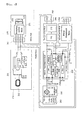
- FIG. 1 is a schematic circuit diagram of an exemplary non-contact power transmission system in accordance with the present invention, which includes a non-contact power transmission apparatus 100 for sending out a wireless power signal and a non-contact power reception apparatus 200 receiving the wireless power signal and charging a battery cell with it.
- the non-contact power transmission apparatus 100 includes a primary core 110, an identifier 120, a wireless power transmission controller 130, a switching controller 140, an operating driver 150, a series resonance converter 160, and a feedback circuit 170.
- the primary core 110 consists of a plurality of power transmission cores 111 and is connected in parallel with the series resonance converter 160.
- the identifier 120 detects a change in the load of the primary core 110 and determines whether the change is induced by the non-contact power reception apparatus 200 or not. Thus, the identifier serves both to detect the change in the load and to analyze and process a data signal code of an AC signal of the signals transmitted from the non-contact power reception apparatus 200.
- the wireless power transmission controller 130 receives and checks the determination result from the identifier 120, and, if the change in the load is induced by the non-contact power reception apparatus 200, sends out a power control signal to the operating driver 150 via the primary core 110 to transmit the wireless power signal.
- the controller 130 analyzes and processes the data signal filtered by the identifier 120 and correspondingly controls the operating driver 150.
- the controller creates a data signal (e.g. an ID asking signal) and transmits it to the non-contact power reception apparatus 200 via the primary core 110.
- a data signal e.g. an ID asking signal
- the switching controller 140 controls the switching operation of a plurality of switches (not shown), which are provided between the series resonance circuit 160 and the power transmission cores 111.
- the operating driver 150 controls the operation of the series resonance converter 160 depending upon the intensity of the wireless power signal that is to be transmitted.
- the series resonance converter 160 creates a transmission power source for creating a wireless power signal to be transmitted under the control of the operating driver 150, and supplies it to the primary core 110.
- the wireless power transmission controller 130 transmits a power control signal for transmitting a wireless power signal, which has a required power value, to the operating driver 150
- the operating driver 150 controls the operation of the series resonance converter 160 to correspond to the transmitted power control signal
- the series resonance converter 160 applies to the primary core 110 a transmission power source, which corresponds to the required power value, under the control of the operating driver 150, thereby transmitting a wireless power signal having the required intensity.
- the feedback circuit 170 extracts the code data of the AC signal from a DC signal applied to the primary core 110.
- the feedback circuit 170 includes an RC filter circuit section (not shown), which is electrically connected with ends of the power transmission cores 111 of the primary core 110 to remove a DC signal component (low frequency component), and an amplifying circuit section (not shown), which has an OP-AMP that is electrically connected with the RC filter circuit section.
- the low frequency signal which is a DC signal component
- the RC filter circuit section is removed by the RC filter circuit section and the extracted AC signal component is amplified by the amplifying circuit section.
- the non-contact power reception apparatus 200 to be supplied with power by receiving the wireless power signal includes a power reception coil 211 of a secondary core 220, which creates induced power using the transmitted wireless power signal, a rectifier 230, which rectifies the induced power, and a battery cell module (not designated), which charges a battery cell 270 with the rectified power.
- This battery module includes a protection circuit, such as an overvoltage and overcurrent prevention circuit, a temperature detecting circuit and the like, and a charging management module, which collects and processes information such as the charged state of the battery cell and the like.
- a protection circuit such as an overvoltage and overcurrent prevention circuit, a temperature detecting circuit and the like
- a charging management module which collects and processes information such as the charged state of the battery cell and the like.
- the non-contact power reception apparatus 200 further includes a wireless power receiver controller, which checks the current induced to the power reception coil 211 of the secondary core 220 and requests the control of the intensity of a wireless power signal based on the information on the charging of the battery cell, which is collected and processed by the battery cell module, and an ID transmitter, which, via the secondary core 220, transmits and receives the code data of an AC signal modulated in an AC modulation manner.
- a wireless power receiver controller which checks the current induced to the power reception coil 211 of the secondary core 220 and requests the control of the intensity of a wireless power signal based on the information on the charging of the battery cell, which is collected and processed by the battery cell module
- an ID transmitter which, via the secondary core 220, transmits and receives the code data of an AC signal modulated in an AC modulation manner.
- the non-contact power reception apparatus 200 further includes a capacitor C, which is connected in parallel with the power reception coil 211 of the secondary core 220 to remove a DC signal component, and a MOSFET, in which a drain terminal is serially connected with the capacitor.
- the MOSFET performs on/off control under the control of the ID transmitter.
- the ID transmitter inputs the operation voltage of the MOSFET to the gate terminal of the MOSFET in correspondence with a duty rate, which is set to correspond to the control request for the intensity of the wireless power signal by the wireless power receiver controller.
- the MOSFET creates and outputs a pulse width modulated (PWM) signal corresponding to voltage input to the gate terminal, and the PWM signal is transmitted to the non-contact power transmission apparatus 100 via the power reception core 211.
- PWM pulse width modulated
- the non-contact power transmission apparatus 100 is supplied with power via a power supply port 181 from an adapter supplied with a regular power source, a power source of a USB port of a portable terminal such as a notebook, or the like.
- the apparatus 100 further includes a current detector 191, which detects the internal current of the apparatus 100, and a temperature detector 192, which detects the internal temperature of the apparatus 100 during the charging process, so that if overheating, overvoltage or overcurrent occurs, the operation can be stopped.
- a current detector 191 which detects the internal current of the apparatus 100
- a temperature detector 192 which detects the internal temperature of the apparatus 100 during the charging process, so that if overheating, overvoltage or overcurrent occurs, the operation can be stopped.
- the battery cell module 230 of the non-contact power reception apparatus 200 further includes a charging circuit 231 for charging a battery cell, a gauge circuit 232 for checking the charged quantity, and a charging monitoring circuit 233 for monitoring the charging state.
- a display 193 is further provided to display the state of operation of the non-contact power transmission apparatus 100 and the charging state of the non-contact power reception apparatus 200.
- non-contact power reception apparatus 200 that is provided with both a charging coil and a communication loop antenna at the same time.
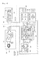
- FIG. 2 is a schematic block diagram of an exemplary non-contact power reception apparatus illustrative of non-contact charging and a control module of data communication in the portable terminals in accordance with the present invention.
- the non-contact power reception apparatus includes a common transmission and reception block 210; a rectification block 220, rectifying an AC wireless power signal and converting the same to a DC wireless power signal; a received-power control block 230, controlling the DC signal converted by the rectification block 220 to be converted into chargeable voltage and current (which can be used in the following construction); a charging control block 240, supplying, to a battery cell block 270, electric energy output from the received-power control block 230; a data processing block 250, analyzing and processing transmitted/received data and performing an electronic settlement process; and the battery cell block 270.
- the battery cell block 270 consists of a rechargeable battery cell 273, a temperature detecting module 272, and a charging monitoring block 271 for protection.
- the common transmission and reception block 210 serves to selectively perform a mode of receiving a wireless power signal to operate the non-contact charging system and a mode of transmitting and receiving data to operate the electronic settlement system, and includes a power reception coil 211, a loop antenna 212, a mode switching unit 213, and a mode control unit 214.
- the power reception coil 211 serves to receive the wireless power signal from the non-contact charging system, and, as shown in FIG. 3 , one end side thereof is connected, at a common contact point, with the loop antenna 212 and output outside the block and another end side thereof is connected with the mode switching unit 213.
- the loop antenna 212 serves to transmit and receive data, such as information on settlement by the electronic settlement system, and as shown in FIG. 3 , one end side thereof is connected, at a common contact point, with the power reception coil 211 and output outside the block, and another end side thereof is connected with the mode switching unit 213.
- the mode switching unit 213 serves to select either one of the power reception coil 211 and the loop antenna 212 and perform a switching operation to allow electrical connection to either one of the rectification block 230 and the data processing block 250.
- the power reception coil 211 and the rectification block 230 are operated to be connected under the control of the mode control unit 214.
- the mode control unit 214 serves to detect a voltage of the power received by the power reception coil 211 and control the switching operation of the mode switching unit 213. Then, the mode control unit compares the detected received-voltage with a reference voltage (a minimum voltage capable of determining a power signal supplied by a non-contact charging system), and outputs the comparison result to the mode switching unit 213.
- a reference voltage a minimum voltage capable of determining a power signal supplied by a non-contact charging system
- the mode control unit 214 performs the control operation so that, if the detected received-voltage is higher than the reference voltage, the mode switching unit 213 performs the switching operation to electrically connect the power reception coil 211 and the rectification block 220, and, if the detected received-voltage is lower than the reference voltage, the mode switching unit 213 performs the switching operation to electrically connect the loop antenna 212 and the data processing block 250.
- the mode control unit 214 includes a voltage detector 214 that is connected to a common contact point between the power reception coil 211 and the loop antenna 212, so as to detect a voltage induced to the power reception coil 211.
- FIG. 4 is a schematic circuit diagram of an exemplary non-contact power reception apparatus in accordance with the present invention.
- the apparatus is configured so that the common transmission and reception module 210 is arranged in a battery pack A such that the module 210 is electrically connected with a first connector module 261 of the battery pack A, and the rectification block 220, the received-power control block 230, the charging control block 240, and the data processing block 250 are arranged in a terminal body B of the portable terminal.
- the terminal body B is configured such that a second connector module 252, which is to be electrically connected with the charging control block 240, is provided so as to be connected with the first connector module 261 of the battery pack A, and such that a third connector module 263 is provided so as to allow the wireless power signal received by the power reception coil 211 to be supplied to the rectification block 220.
- the data that is transmitted/received via the loop antenna 212 communicates with the data processing block 250 via the third connector module 263, and the data processing block 250 analyzes and processes the communicated data and performs a process such as settlement or the like.
- the battery pack A is configured to include a battery cell 273, a temperature detecting module 272, and a charging monitoring module 271 in the battery pack A, which consists of an upper case Aa and a lower case Ab.
- the power reception coil 211 and the loop antenna 212 are mounted on one side of the battery cell 273 such that a shield plate 211a is disposed between the power reception coil 211 and the battery cell 273, and an absorber 212a is arranged between the loop antenna 212 and the battery cell 273.
- the power reception coil 211 and the loop antenna 212 are provided on different pieces of shielding material on the same plane, thereby minimizing the thickness of the battery pack A.
- the power reception coil 211 has a structure in which a plurality of windings is wound around it, and the loop antenna 212 has a loop type structure, so that it is preferred that, as shown in FIG. 6 , the power reception coil 211 is provided in the center of the apparatus, and the loop antenna 212 is provided outside the power reception coil.
- the power reception coil 211 which receives a non-contact wireless power signal and charges a battery
- the loop antenna 212 for data communication for electronic settlement are arranged on the same plane
- the common transmission and reception block 212 which includes the power reception coil 211 and the loop antenna 212, is mounted in the battery pack A, so that the thickness of the battery pack A can be minimized, fabricating costs can be reduced
- the rectification module 220, the received-power control block 230, the charging control block 240, and the data processing block 250 can also use modules mounted in the portable terminal body B.
- FIG. 6 The detailed electrical connection between the respective elements of FIG. 6 or the like is modifiable into various forms by persons skilled in the art, so that it is not limited to the specific construction of FIG. 7 , which is to be described later.
- FIG. 5 is a schematic circuit diagram of an exemplary non-contact power reception apparatus in accordance with the present invention.
- the apparatus is configured so that the common transmission and reception module 210 is arranged in a cover case C such that the module 210 is electrically connected with a fourth connector module 264 of the cover case C, the fourth connector module 264 is connected with a third connector module 263 of the terminal body B, and the rectification block 220, the received-power control block 230, the charging control block 240, and the data processing block 250 are arranged between the third connector module 263 and the second connector module 262 in the terminal body B.
- the second connector module 262 of the terminal body B is connected with the first connector module 261 of the battery pack A.
- the cover case C is configured so that, as shown in FIG. 7 , space (not designated) for the common transmission and reception block 210 is formed in the cover case C, and the power reception coil 211 and the loop antenna 212 are mounted in the space such that a shield plate 211a is disposed on the power reception coil 211, and an absorber 212a is arranged on the loop antenna 212.
- the cover case includes the power reception coil 211 in the center thereof and the loop antenna 212 outside the power reception coil.
- the power reception coil 211 which receives a non-contact wireless power signal and charges a battery
- the loop antenna 212 for data communication for electronic settlement are arranged on the same plane
- the common transmission and reception block 212 which includes the power reception coil 211 and the loop antenna 212, is mounted in the cover case C, so that the thickness of the cover case C can be minimized
- the rectification module 220, the received-power control block 230, the charging control block 240, and the data processing block 250 are mounted in the terminal body B, so that traditional battery packs can continue to be used.
- the power reception cores 211 are preferably fabricated to be thin.
- a coil is used in which a coil wire, which comprises a plurality of thin metal wires, is wound around itself in the winding diameter.
- a shielding sheet is generally provided on one side of a secondary coil in order to protect electric circuit elements from electromagnetic waves.
- the secondary coil is circular, there is no coil near the four corners of the rectangular shield sheet, so that an eddy current is generated, thus raising the temperature.
- the positions of the primary core and the secondary core are variable, so that the mobility and transmission efficiency for the secondary core become an important evaluating reference for the reliability of products.
- the coil may be shaped so that a transmitter and a receiver are circular windings, or otherwise so that the transmitter is circular windings and the receiver is rectangular windings.
- the coil of the receiver is circular, mobility is excellent, whereas power transmission efficiency suffers because area is decreased compared to the rectangular coil. If the coil is rectangular, relative to the circular coil, power transmission efficiency is excellent, but mobility suffers.
- a jig which facilitates fabricating the secondary core for the non-contact reception apparatus, the secondary core is configured to have the shape of both a circle and a rectangle, so that the mobility and transmission efficiency for the secondary core can be advantageously improved at the same time, by combining the advantages of a circular coil and a rectangular coil.
- FIG. 8 is a partially cut away perspective view of an exemplary jig for fabricating the non-contact power reception apparatus, showing a double-structure core 320 wound around the coil-winding jig 310, the double-structure core consisting of circular and rectangular core portions.
- the coil-winding jig 310 includes a lower disk 311, an upper disk 312, and a guide unit 313 guiding the double-structure core 320 so that the circular and rectangular core portions are separately wound around the coil-winding jig 310.
- the lower disk 311 is formed in a planar form as shown in FIG. 9 , and has a winding protrusion 311a, about which the double-structure core is wound, in the center of the upper surface thereof.
- the height of the winding protrusion 311a be greater than the height (diameter) of the coil wire.
- a through-hole 311b is formed adjacent to the winding protrusion 311a, as shown in FIG. 3 .
- the through-hole 311b passes through the lower disk 311, and is formed at an incline, preferably, as shown in FIG. 13 .
- the inclined through-hole 311b prevents the coil wire from being drawn up towards the upper portion of the lower disk 311 when the double-structure core 320 is wound.
- the upper disk 312 is placed above the lower disk at a certain distance therefrom, and is formed in a planar form, preferably like the lower disk 311, as shown in FIG. 9 .
- a separate holder holds and fixes one side (opposite corner or the like) of the upper disk 312, so that the upper disk can be separated from the lower disk 311.
- the upper disk 312 has at least one slide hole 312a, and preferably, at least four slide holes.
- the guide unit 313 is inserted into the slide hole 312a in the upper disk 312 so that the guide unit is movable in a vertical direction. It is preferred that, as shown in FIG. 9 , if the outer surface extends, an imaginary rectangle is formed, and if the inner surface extends, an imaginary circle is formed.
- the guide unit 313 has a shape corresponding to the corners of a rectangle (preferably, a rectangular plane having a certain thickness) and an inner curved section 313a corresponding to a circle.
- various kinds of separate devices for controlling the construction of the present invention such as a separator for separating the upper disk 312, a winder for coiling wire, and the like, may be adopted, without being limited to a specific one, as desired by those skilled in the art.
- a coil wire (not designated) as a basic unit of the double-structure core 320 is inserted into the through-hole 311b of the lower disk 311 from a lower side thereof and drawn upwards.
- the coil wire may of course be inserted into the through-hole from the upper side thereof and drawn downwards.
- the drawn coil wire is circularly wound about the winding protrusion 311a to form a first coil 321.
- winding protrusion 311a is provided to have the same height as the thickness (height) of the coil wire and the undersurface of the upper disk 312 is separated by the height of the winding protrusion 311a, winding the coil wire is of course easily performed.
- the diameter of the first coil 321 increases to reach an imaginary circular diameter by the inner curved section 313a of the guide unit 313 as the coil wire is wound, winding the coil wire stops and the formation of the first coil 321 is completed.
- the guide units 313 provided in the upper disk 321 are slid and lowered.
- the curved section 313a of the guide unit 313 come close to the outer circumference of the first coil 321.
- the coil wire is wound around the outer surface of the guide unit 313 to form a second coil 322.
- the coil wire for forming the second coil 322 may be different from that for the first coil 321, but it is preferred that the coil wire forming the first coil 321 be continuously used while extending from the first coil.
- the formation of the second coil 322 is completed.
- the double-structure core 320 consisting of first and second coils 321 and 322, is removed from the coil-winding jig 310.
- the wireless power transmission double-structure core is fabricated such that the first circular coil 321 is provided in the center thereof and the second rectangular coil 322 is provided outside the first coil, so that the core with advantageous circular and rectangular coils have can be accomplished.
Abstract
Description
- The present invention relates to a non-contact power reception apparatus and a jig for fabricating a core for the non-contact power reception apparatus, and more particularly to a non-contact power reception apparatus, in which a power reception coil for a charging system and a loop antenna for an electronic settlement system are mounted on a battery pack and a cover case of a portable terminal such that the power reception coil is arranged in the center thereof and the loop antenna is disposed outside the power reception coil, so that a mode of receiving a wireless power signal and a mode of transmitting and receiving data are selectively performed, thereby preventing interference from harmonic components and enabling non-contact charging and electronic settlement using a single portable terminal, and a jig for fabricating a core to be mounted to the non-contact power reception apparatus.
- Generally, a battery pack is a kind of power supply that is charged with power (electric energy) received from an external charger and supplies the power so that portable electronic devices, such as cellular phones, personal digital assistants (PDAs) and the like can be operated, and consists of a battery cell which is charged with electric energy and circuits for charging and discharging the battery cell (supplying electric energy to portable terminals).
- The electrical connection between the battery pack, which is used in the portable terminals, and the charger for charging electric energy to the battery pack may be achieved using a connector supply system, which receives the power from a regular power source and converts the voltage and current thereof to correspond to those of the battery pack, and supplies the electric power to the battery pack via a connector of the corresponding battery pack.
- However, when the charger and the batteries are connected or disconnected to replenish the electric power of the batteries using such a connector supply system, there may be drawbacks, such as instant discharge owing to the difference in potential between the charger connector and the battery connector, the risk of fire and concomitant damage due to fire caused by the presence of foreign substances gathered on both connectors, and the like.
- Further, accumulated humidity will cause the discharge of the battery through the battery connector and other problems will occur, such as the reduction in the life and performance of the battery pack, and the like.
- To solve the above-mentioned problems, a non-contact charging system using a wireless power transmission and reception system was recently proposed.
- Meanwhile, portable terminals that have recently proliferated include an electronic settlement system using a Local Area Network (LAN), so that settlement is carried out by bringing the portable terminals into proximity with electronic settlement devices and conducting a settlement process.
- Such an electronic settlement system essentially includes a loop antenna, an absorber, an impedance matching circuit and the like in the portable terminal.
- In order to mount, in a single portable terminal, both the non-contact charging system using the wireless power transmission and reception technology and the settlement system using the LAN, a power reception coil of the charging system and the loop antenna of the electronic settlement system should be mounted in the portable terminal and operated.
- However, due to interference from harmonic components (n times a fundamental wave), which is produced in the frequency band (e.g. 13,56MHz) of the electronic settlement system and the frequency band (e.g. hundreds kHz) of the charging system, problems such as the unstable transmission of signals occur, therefore failing to perform desired functions.
- The information disclosed in this Background of the Invention section is only for the enhancement of understanding of the background of the invention and should not be taken as an acknowledgment or any form of suggestion that this information forms the prior art that would already be known to a person skilled in the art.
- To solve the above-mentioned problem, the present invention is directed to a non-contact power reception apparatus, in which a power reception coil for a charging system and a loop antenna for an electronic settlement system are mounted on a battery pack and a cover case of a portable terminal while interference from harmonic components is prevented, thereby enabling non-contact charging and electronic settlement using a single portable terminal.
- Another object of the present invention is to provide a non-contact power reception apparatus having the power reception coil arranged in the center thereof and the loop antenna disposed outside the power reception coil, so that a mode of receiving a wireless power signal and a mode of transmitting and receiving data are selectively performed.
- A further object of the present invention is to provide a jig for fabricating a double-structure core which is mounted in the non-contact power reception apparatus.
- The information disclosed in this Background of the Invention section is only for the enhancement of understanding of the background of the invention and should not be taken as an acknowledgment or any form of suggestion that this information forms the prior art that would already be known to a person skilled in the art.
- In accordance with an aspect of the present invention, the non-contact power reception apparatus may include a common transmission and reception block selectively performing a mode of receiving a wireless power signal and a mode of transmitting and receiving data, a rectification block rectifying the power signal received by the common transmission and reception block in the mode of receiving the wireless power signal, a received-power control block controlling the power signal rectified by the rectification block, a charging control block controlling charging of a battery pack using electric energy of the power signal controlled by the received-power control block, and a data processing block transmitting and receiving data for electronic settlement with an external electronic device via the common transmission and reception block in the mode of transmitting and receiving data.
- The common transmission and reception block may include a power reception coil receiving the wireless power signal, a loop antenna for the transmission and reception of data, a mode switching unit selecting either one of the power reception coil and the loop antenna and allowing electrical connection to either one of the rectification block and the data processing block, and a mode control unit detecting a received-voltage of the power reception coil and controlling a switching operation of the mode switching unit.
- The mode control unit may perform a control operation so that, if the detected received-voltage is higher than a reference voltage, the mode switching unit performs the switching operation to electrically connect the power reception coil and the rectification block, and if the detected received-voltage is lower than the reference voltage, the mode switching unit performs the switching operation to electrically connect the loop antenna and the data processing block.
- The mode control unit may include a voltage detector for detecting the received-voltage of the power reception coil, comparing the detected received-voltage with the reference voltage and outputting the comparison result.
- In accordance with another aspect of the present invention, the non-contact power reception apparatus may include, in a portable terminal, a common transmission and reception block selectively performing a mode of receiving a wireless power signal and a mode of transmitting and receiving data, a rectification block rectifying the power signal received by the common transmission and reception block in the mode of receiving the wireless power signal, a received-power control block controlling the power signal rectified by the rectification block, a charging control block controlling charging of a battery pack using electric energy of the power signal controlled by the received-power control block, and a data processing block transmitting and receiving data for electronic settlement with an external electronic device via the common transmission and reception block in the mode of transmitting and receiving data. The portable terminal may include a terminal body capable of performing wireless communication, a rechargeable battery pack supplying electric energy to the terminal body, a cover case for protection of the battery pack, and at least one connector module electrically connecting the respective terminal body, the battery pack and the cover case, in which a first connector module of the battery pack is connected with a second connector module of the terminal body, in which the common transmission and reception block is arranged in the battery pack in such a manner as to be connected with the first connector module of the battery pack and a third connector module of the terminal body, in which the rectification block, the reception power control block and the charging block are sequentially arranged in the terminal body to extend from the third connector module to the second connector module, and in which the data processing block is arranged between the third connector module and the received-power control module.
- In accordance with further another aspect of the present invention, the non-contact power reception apparatus may include, in a portable terminal, a common transmission and reception block selectively performing a mode of receiving a wireless power signal and a mode of transmitting and receiving data, a rectification block rectifying the power signal received by the common transmission and reception block in the mode of receiving the wireless power signal, a received-power control block controlling the power signal rectified by the rectification block, a charging control block controlling charging of a battery pack using electric energy of the power signal controlled by the received-power control block, and a data processing block transmitting and receiving data for electronic settlement with an external electronic device via the common transmission and reception block in the mode of transmitting and receiving data. The portable terminal may include a terminal body capable of performing wireless communication, a rechargeable battery pack supplying electric energy to the terminal body, a cover case for protection of the battery pack, and at least one connector module electrically connecting the terminal body, the battery pack and the cover case, in which a first connector module of the battery pack is connected with a second connector module of the terminal body, in which the common transmission and reception block is arranged in the cover case in such a manner as to be connected with a fourth connector module of the cover case, the fourth connector module being connected with a third connector of the terminal body, in which the rectification block, the reception power control block and the charging block are sequentially arranged in the terminal body to extend from the third connector module to a second connector module, and in which the data processing block is arranged between the third connector module and the received-power control module, the second connector module being connected with a first connector module of the battery pack.
- A connector of the fourth connector module, which is connected with the common transmission and reception block arranged in the cover case, may have a shape of a leaf spring, and be electrically connected with a connector of the first connector module of the battery pack via a through-hole provided in a cover of the cover case.
- The common transmission and reception block may include a power reception coil receiving the wireless power signal, a loop antenna for transmission and reception of data, a mode switching unit selecting any one of the power reception coil and the loop antenna and allowing electrical connection to any one of the rectification block and the data processing block, and a mode control unit detecting a received-voltage of the power reception coil and controlling a switching operation of the mode switching unit.
- The mode control unit may perform a control operation so that if the detected received-voltage is higher than a reference voltage, the mode switching unit performs the switching operation to electrically connect the power reception coil and the rectification block, and if the detected received-voltage is lower than the reference voltage, the mode switching unit performs the switching operation to electrically connect the loop antenna and the data processing block.
- The mode control unit may include a voltage detector for detecting the received-voltage of the power reception coil, comparing the detected received-voltage with the reference voltage and outputting the comparison result.
- In accordance with still another aspect of the present invention, the jig for fabricating a core for a non-contact power reception apparatus may include a lower planar disk having a center winding protrusion thereon, an upper planar disk placed on the lower disk and having at least one slide hole therein, and at least one guide unit inserted into the slide hole so as to be vertically movable.
- The lower disk may have a through-hole adjacent to the winding protrusion.
- The guide unit may have a shape corresponding to a rectangular corner and an inner curved section.
- In accordance with yet another aspect of the present invention, the method of fabricating a double-structure core using the jig for the non-contact power reception apparatus may include steps of: a) inserting a coil wire into the through-hole of the lower disk from a lower side thereof and drawing the coil wire upwards, b) winding the drawn coil wire about the winding protrusion to form a first coil, c) after the completion of formation of the first coil, sliding and lowering a plurality of guide units disposed in the upper disk, d) winding a coil wire around an outer surface of the guide unit to form a second coil, and e) separating the first and second coils from a jig for winding a coil.
- The step b) includes b-1) winding the coil wire about the winding protrusion to extend the diameter of the first coil, and b-2), if the diameter of the first coil matches that of an imaginary circle formed by the curved surface of the guide unit, completing the formation of the first coil.
- The step d) includes d-1) winding the coil wire extending from the first coil about an imaginary rectangle defined by the outer surface of the guide unit to form the second coil, and d-2), if the size of the second coil matches the size of the lower or upper disk, completing the formation of the second coil.
- According to the above-mentioned construction, the present invention has the following effects:
- The power reception coil of the charging system and the loop antenna of the electronic settlement system are mounted in the battery pack and the cover case of the portable terminal, so that non-contact charging and electronic settlement are both performed in the single portable terminal.
- Particularly, the non-contact charging system and the electronic settlement system, which use different respective frequency bands, are operated at the same time and interference between the two systems is prevented, so that the reliability is improved.
- The control modules of the non-contact charging system using the wireless power transmission and reception technology and the electronic settlement system using LAN are arranged in diverse forms, so that non-contact charging and electronic settlement can be carried out for battery packs having diverse structures.
- In fabricating the core for the non-contact reception apparatus using the jig, the corresponding core is configured to have the shape of both a circle and a rectangle, so that the mobility and transmission efficiency of the corresponding core (secondary side) can be advantageously improved at the same time, by combining the advantages of a circular coil and a rectangular coil.
- Thus, adaptability to various kinds of portable terminals and the like can be considerably improved.
- The jig for winding a coil, which facilitates fabricating the core, and the method of easily fabricating the core using the jig are further provided, thereby having effects of improved productivity, reduced cost, increased production and the like in fabricating the double-structure core.
- Thus, the reliability of the non-contact charging system that includes the non-contact power reception apparatus and the non-contact power transmission apparatus can be improved, as can the competitiveness of related products, such as portable terminals, battery packs, and the like.
- The methods and apparatuses of the present invention have other features and advantages which will be apparent from or are set forth in more detail in the accompanying drawings, which are incorporated herein, and the following Detailed Description of the Invention, which together serve to explain certain principles of the present invention.
- The methods and apparatuses of the present invention have other features and advantages which will be apparent from or are set forth in more detail in the accompanying drawings, which are incorporated herein, and the following Detailed Description of the Invention, which together serve to explain certain principles of the present invention.
-
-
FIG. 1 is a schematic circuit diagram of an exemplary non-contact power reception apparatus in accordance with the present invention; -
FIG. 2 is a schematic block diagram of another exemplary non-contact power reception apparatus in accordance with the present invention; -
FIG. 3 is a schematic circuit diagram of an exemplary common transmission and reception block ofFIG. 2 ; -
FIG. 4 is a schematic circuit diagram of another exemplary non-contact power reception apparatus in accordance with the present invention; -
FIG. 5 is a schematic circuit diagram of another exemplary non-contact power reception apparatus in accordance with the present invention; -
FIG. 6 is an exploded perspective view of an exemplary battery pack for portable terminals in accordance with the present invention; -
FIG. 7 is an exploded perspective view of an exemplary battery pack and a cover case for portable terminals; -
FIG. 8 is a partially cut away perspective view of an exemplary jig for fabricating a core for the non-contact power reception apparatus in accordance with the present invention; -
FIG. 9 is an exploded perspective view of the jig ofFIG. 8 ; -
FIGS. 10 and11 are perspective views illustrative of a procedure of fabricating a double-structure core using the jig ofFIG. 8 ; -
FIG. 12 is a perspective view of the double-structure core fabricated using the jig ofFIG. 8 ; and -
FIG. 13 is a cross-sectional view illustrative of the procedure shown inFIGS. 10 and11 . - Reference will now be made in detail to various embodiments of the present invention(s), examples of which are illustrated in the accompanying drawings and described below. While the invention(s) will be described in conjunction with exemplary embodiments, it will be understood that the present description is not intended to limit the invention(s) to those exemplary embodiments. On the contrary, the invention(s) is/are intended to cover not only the exemplary embodiments, but also various alternatives, modifications, equivalents and other embodiments, which may be included within the spirit and scope of the invention as defined by the appended claims.
- A non-contact power reception apparatus and a jig for fabricating a core for the power reception apparatus according to the present invention are variously applicable, and preferred embodiments thereof will now be described in detail with reference to the accompanying drawings.
-
FIG. 1 is a schematic circuit diagram of an exemplary non-contact power transmission system in accordance with the present invention, which includes a non-contactpower transmission apparatus 100 for sending out a wireless power signal and a non-contactpower reception apparatus 200 receiving the wireless power signal and charging a battery cell with it. - The non-contact
power transmission apparatus 100 includes a primary core 110, anidentifier 120, a wirelesspower transmission controller 130, a switching controller 140, an operatingdriver 150, aseries resonance converter 160, and a feedback circuit 170. - The primary core 110 consists of a plurality of
power transmission cores 111 and is connected in parallel with theseries resonance converter 160. - The
identifier 120 detects a change in the load of the primary core 110 and determines whether the change is induced by the non-contactpower reception apparatus 200 or not. Thus, the identifier serves both to detect the change in the load and to analyze and process a data signal code of an AC signal of the signals transmitted from the non-contactpower reception apparatus 200. - The wireless
power transmission controller 130 receives and checks the determination result from theidentifier 120, and, if the change in the load is induced by the non-contactpower reception apparatus 200, sends out a power control signal to theoperating driver 150 via the primary core 110 to transmit the wireless power signal. - Then, the
controller 130 analyzes and processes the data signal filtered by theidentifier 120 and correspondingly controls the operatingdriver 150. In addition, the controller creates a data signal (e.g. an ID asking signal) and transmits it to the non-contactpower reception apparatus 200 via the primary core 110. - The switching controller 140 controls the switching operation of a plurality of switches (not shown), which are provided between the
series resonance circuit 160 and thepower transmission cores 111. - The operating
driver 150 controls the operation of theseries resonance converter 160 depending upon the intensity of the wireless power signal that is to be transmitted. - The
series resonance converter 160 creates a transmission power source for creating a wireless power signal to be transmitted under the control of the operatingdriver 150, and supplies it to the primary core 110. - That is, when the wireless
power transmission controller 130 transmits a power control signal for transmitting a wireless power signal, which has a required power value, to theoperating driver 150, the operatingdriver 150 controls the operation of theseries resonance converter 160 to correspond to the transmitted power control signal, and theseries resonance converter 160 applies to the primary core 110 a transmission power source, which corresponds to the required power value, under the control of the operatingdriver 150, thereby transmitting a wireless power signal having the required intensity. - When the primary core 110 receives the code data of an AC signal, the feedback circuit 170 extracts the code data of the AC signal from a DC signal applied to the primary core 110. The feedback circuit 170 includes an RC filter circuit section (not shown), which is electrically connected with ends of the
power transmission cores 111 of the primary core 110 to remove a DC signal component (low frequency component), and an amplifying circuit section (not shown), which has an OP-AMP that is electrically connected with the RC filter circuit section. - That is, the low frequency signal, which is a DC signal component, is removed by the RC filter circuit section and the extracted AC signal component is amplified by the amplifying circuit section.
- Thus, it is possible to transmit and receive a low-amplitude signal.
- The non-contact
power reception apparatus 200 to be supplied with power by receiving the wireless power signal includes apower reception coil 211 of asecondary core 220, which creates induced power using the transmitted wireless power signal, arectifier 230, which rectifies the induced power, and a battery cell module (not designated), which charges abattery cell 270 with the rectified power. - This battery module includes a protection circuit, such as an overvoltage and overcurrent prevention circuit, a temperature detecting circuit and the like, and a charging management module, which collects and processes information such as the charged state of the battery cell and the like.
- The non-contact
power reception apparatus 200 further includes a wireless power receiver controller, which checks the current induced to thepower reception coil 211 of thesecondary core 220 and requests the control of the intensity of a wireless power signal based on the information on the charging of the battery cell, which is collected and processed by the battery cell module, and an ID transmitter, which, via thesecondary core 220, transmits and receives the code data of an AC signal modulated in an AC modulation manner. - The non-contact
power reception apparatus 200 further includes a capacitor C, which is connected in parallel with thepower reception coil 211 of thesecondary core 220 to remove a DC signal component, and a MOSFET, in which a drain terminal is serially connected with the capacitor. - The MOSFET performs on/off control under the control of the ID transmitter. The ID transmitter inputs the operation voltage of the MOSFET to the gate terminal of the MOSFET in correspondence with a duty rate, which is set to correspond to the control request for the intensity of the wireless power signal by the wireless power receiver controller.
- That is, when the ID transmitter inputs an on-signal and an off-signal, which correspond to the operation voltage, to the gate terminal, the MOSFET creates and outputs a pulse width modulated (PWM) signal corresponding to voltage input to the gate terminal, and the PWM signal is transmitted to the non-contact
power transmission apparatus 100 via thepower reception core 211. - The non-contact
power transmission apparatus 100 is supplied with power via apower supply port 181 from an adapter supplied with a regular power source, a power source of a USB port of a portable terminal such as a notebook, or the like. - The
apparatus 100 further includes acurrent detector 191, which detects the internal current of theapparatus 100, and atemperature detector 192, which detects the internal temperature of theapparatus 100 during the charging process, so that if overheating, overvoltage or overcurrent occurs, the operation can be stopped. - The
battery cell module 230 of the non-contactpower reception apparatus 200 further includes a charging circuit 231 for charging a battery cell, a gauge circuit 232 for checking the charged quantity, and a charging monitoring circuit 233 for monitoring the charging state. - A
display 193 is further provided to display the state of operation of the non-contactpower transmission apparatus 100 and the charging state of the non-contactpower reception apparatus 200. - With regard to the fabrication of the
power reception coil 211 of thesecondary side core 220 of the non-contactpower reception apparatus 200, a description thereof will be made later. - Hereinafter, reference will be made to the embodiment of the non-contact
power reception apparatus 200 that is provided with both a charging coil and a communication loop antenna at the same time. -
FIG. 2 is a schematic block diagram of an exemplary non-contact power reception apparatus illustrative of non-contact charging and a control module of data communication in the portable terminals in accordance with the present invention. The non-contact power reception apparatus includes a common transmission andreception block 210; arectification block 220, rectifying an AC wireless power signal and converting the same to a DC wireless power signal; a received-power control block 230, controlling the DC signal converted by therectification block 220 to be converted into chargeable voltage and current (which can be used in the following construction); a chargingcontrol block 240, supplying, to abattery cell block 270, electric energy output from the received-power control block 230; adata processing block 250, analyzing and processing transmitted/received data and performing an electronic settlement process; and thebattery cell block 270. - Here, the
battery cell block 270 consists of arechargeable battery cell 273, atemperature detecting module 272, and a chargingmonitoring block 271 for protection. - The common transmission and
reception block 210 serves to selectively perform a mode of receiving a wireless power signal to operate the non-contact charging system and a mode of transmitting and receiving data to operate the electronic settlement system, and includes apower reception coil 211, aloop antenna 212, amode switching unit 213, and amode control unit 214. - The
power reception coil 211 serves to receive the wireless power signal from the non-contact charging system, and, as shown inFIG. 3 , one end side thereof is connected, at a common contact point, with theloop antenna 212 and output outside the block and another end side thereof is connected with themode switching unit 213. - The
loop antenna 212 serves to transmit and receive data, such as information on settlement by the electronic settlement system, and as shown inFIG. 3 , one end side thereof is connected, at a common contact point, with thepower reception coil 211 and output outside the block, and another end side thereof is connected with themode switching unit 213. - The
mode switching unit 213 serves to select either one of thepower reception coil 211 and theloop antenna 212 and perform a switching operation to allow electrical connection to either one of therectification block 230 and thedata processing block 250. In a state of allowing theloop antenna 212 and thedata processing block 250 to be connected, thepower reception coil 211 and therectification block 230 are operated to be connected under the control of themode control unit 214. - The
mode control unit 214 serves to detect a voltage of the power received by thepower reception coil 211 and control the switching operation of themode switching unit 213. Then, the mode control unit compares the detected received-voltage with a reference voltage (a minimum voltage capable of determining a power signal supplied by a non-contact charging system), and outputs the comparison result to themode switching unit 213. - That is, after detecting a voltage received by the
power reception coil 211, themode control unit 214 performs the control operation so that, if the detected received-voltage is higher than the reference voltage, themode switching unit 213 performs the switching operation to electrically connect thepower reception coil 211 and therectification block 220, and, if the detected received-voltage is lower than the reference voltage, themode switching unit 213 performs the switching operation to electrically connect theloop antenna 212 and thedata processing block 250. - The
mode control unit 214, as shown inFIG. 3 , includes avoltage detector 214 that is connected to a common contact point between thepower reception coil 211 and theloop antenna 212, so as to detect a voltage induced to thepower reception coil 211. - As shown in
FIGS. 4 and5 , reference will now be made to an example in which non-contact charging and the control module of data communication in the portable terminals have been adapted according to the present invention. -
FIG. 4 is a schematic circuit diagram of an exemplary non-contact power reception apparatus in accordance with the present invention. Referring also toFIG. 6 , the apparatus is configured so that the common transmission andreception module 210 is arranged in a battery pack A such that themodule 210 is electrically connected with afirst connector module 261 of the battery pack A, and therectification block 220, the received-power control block 230, the chargingcontrol block 240, and thedata processing block 250 are arranged in a terminal body B of the portable terminal. - Here, the terminal body B is configured such that a second connector module 252, which is to be electrically connected with the charging
control block 240, is provided so as to be connected with thefirst connector module 261 of the battery pack A, and such that athird connector module 263 is provided so as to allow the wireless power signal received by thepower reception coil 211 to be supplied to therectification block 220. - The data that is transmitted/received via the
loop antenna 212 communicates with thedata processing block 250 via thethird connector module 263, and thedata processing block 250 analyzes and processes the communicated data and performs a process such as settlement or the like. - Meanwhile, as shown in
FIG. 6 , the battery pack A is configured to include abattery cell 273, atemperature detecting module 272, and a chargingmonitoring module 271 in the battery pack A, which consists of an upper case Aa and a lower case Ab. - The
power reception coil 211 and theloop antenna 212 are mounted on one side of thebattery cell 273 such that ashield plate 211a is disposed between thepower reception coil 211 and thebattery cell 273, and anabsorber 212a is arranged between theloop antenna 212 and thebattery cell 273. - That is, the
power reception coil 211 and theloop antenna 212 are provided on different pieces of shielding material on the same plane, thereby minimizing the thickness of the battery pack A. - Here, the
power reception coil 211 has a structure in which a plurality of windings is wound around it, and theloop antenna 212 has a loop type structure, so that it is preferred that, as shown inFIG. 6 , thepower reception coil 211 is provided in the center of the apparatus, and theloop antenna 212 is provided outside the power reception coil. - Thus, according to the arrangement shown in
FIGS. 4 and6 , thepower reception coil 211, which receives a non-contact wireless power signal and charges a battery, and theloop antenna 212 for data communication for electronic settlement are arranged on the same plane, and the common transmission andreception block 212, which includes thepower reception coil 211 and theloop antenna 212, is mounted in the battery pack A, so that the thickness of the battery pack A can be minimized, fabricating costs can be reduced, and therectification module 220, the received-power control block 230, the chargingcontrol block 240, and thedata processing block 250 can also use modules mounted in the portable terminal body B. - The detailed electrical connection between the respective elements of
FIG. 6 or the like is modifiable into various forms by persons skilled in the art, so that it is not limited to the specific construction ofFIG. 7 , which is to be described later. -
FIG. 5 is a schematic circuit diagram of an exemplary non-contact power reception apparatus in accordance with the present invention. Referring also toFIG. 7 , the apparatus is configured so that the common transmission andreception module 210 is arranged in a cover case C such that themodule 210 is electrically connected with afourth connector module 264 of the cover case C, thefourth connector module 264 is connected with athird connector module 263 of the terminal body B, and therectification block 220, the received-power control block 230, the chargingcontrol block 240, and thedata processing block 250 are arranged between thethird connector module 263 and thesecond connector module 262 in the terminal body B. - The
second connector module 262 of the terminal body B is connected with thefirst connector module 261 of the battery pack A. - Meanwhile, the cover case C is configured so that, as shown in
FIG. 7 , space (not designated) for the common transmission andreception block 210 is formed in the cover case C, and thepower reception coil 211 and theloop antenna 212 are mounted in the space such that ashield plate 211a is disposed on thepower reception coil 211, and anabsorber 212a is arranged on theloop antenna 212. - Here, as shown in
FIG. 7 , preferably, the cover case includes thepower reception coil 211 in the center thereof and theloop antenna 212 outside the power reception coil. - Thus, according to the arrangement shown in
FIGS. 5 and7 , thepower reception coil 211, which receives a non-contact wireless power signal and charges a battery, and theloop antenna 212 for data communication for electronic settlement are arranged on the same plane, and the common transmission andreception block 212, which includes thepower reception coil 211 and theloop antenna 212, is mounted in the cover case C, so that the thickness of the cover case C can be minimized, and therectification module 220, the received-power control block 230, the chargingcontrol block 240, and thedata processing block 250 are mounted in the terminal body B, so that traditional battery packs can continue to be used. - Meanwhile, in order to minimize the size of the non-contact power transmission apparatus and the non-contact power reception apparatus, the
power reception cores 211 according to the above embodiments are preferably fabricated to be thin. Thus, a coil is used in which a coil wire, which comprises a plurality of thin metal wires, is wound around itself in the winding diameter. - In non-contact charging, a shielding sheet is generally provided on one side of a secondary coil in order to protect electric circuit elements from electromagnetic waves.
- Here, if the secondary coil is circular, there is no coil near the four corners of the rectangular shield sheet, so that an eddy current is generated, thus raising the temperature.
- Due to the non-contact power transmission nature, the positions of the primary core and the secondary core are variable, so that the mobility and transmission efficiency for the secondary core become an important evaluating reference for the reliability of products.
- Generally, the coil may be shaped so that a transmitter and a receiver are circular windings, or otherwise so that the transmitter is circular windings and the receiver is rectangular windings.
- Here, if the coil of the receiver is circular, mobility is excellent, whereas power transmission efficiency suffers because area is decreased compared to the rectangular coil. If the coil is rectangular, relative to the circular coil, power transmission efficiency is excellent, but mobility suffers.
- According to the present invention, a jig is provided which facilitates fabricating the secondary core for the non-contact reception apparatus, the secondary core is configured to have the shape of both a circle and a rectangle, so that the mobility and transmission efficiency for the secondary core can be advantageously improved at the same time, by combining the advantages of a circular coil and a rectangular coil.
-
FIG. 8 is a partially cut away perspective view of an exemplary jig for fabricating the non-contact power reception apparatus, showing a double-structure core 320 wound around the coil-windingjig 310, the double-structure core consisting of circular and rectangular core portions. - The coil-winding
jig 310 includes alower disk 311, anupper disk 312, and aguide unit 313 guiding the double-structure core 320 so that the circular and rectangular core portions are separately wound around the coil-windingjig 310. - The
lower disk 311 is formed in a planar form as shown inFIG. 9 , and has a windingprotrusion 311a, about which the double-structure core is wound, in the center of the upper surface thereof. - Here, it is preferred that the height of the winding
protrusion 311a be greater than the height (diameter) of the coil wire. - A through-
hole 311b is formed adjacent to the windingprotrusion 311a, as shown inFIG. 3 . - The through-
hole 311b passes through thelower disk 311, and is formed at an incline, preferably, as shown inFIG. 13 . The inclined through-hole 311b prevents the coil wire from being drawn up towards the upper portion of thelower disk 311 when the double-structure core 320 is wound. - The
upper disk 312 is placed above the lower disk at a certain distance therefrom, and is formed in a planar form, preferably like thelower disk 311, as shown inFIG. 9 . - Here, various methods of separating and fixing the lower and
upper disks - For example, a separate holder holds and fixes one side (opposite corner or the like) of the
upper disk 312, so that the upper disk can be separated from thelower disk 311. - The
upper disk 312 has at least oneslide hole 312a, and preferably, at least four slide holes. - The
guide unit 313 is inserted into theslide hole 312a in theupper disk 312 so that the guide unit is movable in a vertical direction. It is preferred that, as shown inFIG. 9 , if the outer surface extends, an imaginary rectangle is formed, and if the inner surface extends, an imaginary circle is formed. - That is, the
guide unit 313 has a shape corresponding to the corners of a rectangle (preferably, a rectangular plane having a certain thickness) and an innercurved section 313a corresponding to a circle. - Hereinafter, a method of fabricating a double-
structure core 320 using thejig 310 for the non-contact power reception apparatus will be described with reference toFIGS. 10 and11 . - Here, various kinds of separate devices for controlling the construction of the present invention, such as a separator for separating the
upper disk 312, a winder for coiling wire, and the like, may be adopted, without being limited to a specific one, as desired by those skilled in the art. - First, a coil wire (not designated) as a basic unit of the double-
structure core 320 is inserted into the through-hole 311b of thelower disk 311 from a lower side thereof and drawn upwards. - Here, as desired by a person skilled in the art, the coil wire may of course be inserted into the through-hole from the upper side thereof and drawn downwards.
- The drawn coil wire is circularly wound about the winding
protrusion 311a to form afirst coil 321. - Here, in the case where the winding
protrusion 311a is provided to have the same height as the thickness (height) of the coil wire and the undersurface of theupper disk 312 is separated by the height of the windingprotrusion 311a, winding the coil wire is of course easily performed. - If the diameter of the
first coil 321 increases to reach an imaginary circular diameter by the innercurved section 313a of theguide unit 313 as the coil wire is wound, winding the coil wire stops and the formation of thefirst coil 321 is completed. - After the completion of the formation of the
first coil 321, theguide units 313 provided in theupper disk 321 are slid and lowered. - Here, it is preferred that the
curved section 313a of theguide unit 313 come close to the outer circumference of thefirst coil 321. - When the lower surface of the
guide unit 313 has come close to the upper surface of thelower disk 312 through the above process, the coil wire is wound around the outer surface of theguide unit 313 to form asecond coil 322. - Here, the coil wire for forming the
second coil 322 may be different from that for thefirst coil 321, but it is preferred that the coil wire forming thefirst coil 321 be continuously used while extending from the first coil. - If the
second coil 322 formed by the coil wire corresponds to the area (size) of the lower orupper disk FIG. 11 , the formation of thesecond coil 322 is completed. - After the double-
structure core 320 has been completely fabricated through the above process, the double-structure core 320, consisting of first andsecond coils jig 310. - Thus, the wireless power transmission double-structure core is fabricated such that the first
circular coil 321 is provided in the center thereof and the secondrectangular coil 322 is provided outside the first coil, so that the core with advantageous circular and rectangular coils have can be accomplished. - As set forth above, non-contact charging, the data communication control module and its arrangement in the portable terminal have been described above. It is understood that the technical construction of the present invention may be modified to have different forms without departing from the spirit and essential features of the present invention by those skilled in the art.
- Therefore, the above-mentioned embodiments are provided only for illustrative purposes in all aspects, and the invention is not limited thereto. It should be understood that the scope of the present invention is defined not by the above detailed description, but by the appended claims, and that the described embodiments and all variations or modifications that can be deduced from equivalents interpreted from the claims fall within the scope of the present invention.
Claims (16)
- A non-contact power reception apparatus comprising:a common transmission and reception block selectively performing a mode of receiving a wireless power signal and a mode of transmitting and receiving data;a rectification block rectifying the power signal received by the common transmission and reception block in the mode of receiving the wireless power signal;a received-power control block controlling the power signal rectified by the rectification block, a charging control block controlling charging of a battery pack using electric energy of the power signal controlled by the received-power control block; anda data processing block transmitting and receiving data for electronic settlement with an external electronic device via the common transmission and reception block in the mode of transmitting and receiving data.
- The non-contact power reception apparatus according to claim 1, wherein the common transmission and reception block includes:a power reception coil receiving the wireless power signal;a loop antenna for the transmission and reception of data;a mode switching unit selecting either one of the power reception coil and the loop antenna and allowing electrical connection to either one of the rectification block and the data processing block; anda mode control unit detecting a received-voltage of the power reception coil and controlling a switching operation of the mode switching unit.
- The non-contact power reception apparatus according to claim 2, wherein the mode control unit performs a control operation so that,
if the detected received-voltage is higher than a reference voltage, the mode switching unit performs the switching operation to electrically connect the power reception coil and the rectification block, and
if the detected received-voltage is lower than the reference voltage, the mode switching unit performs the switching operation to electrically connect the loop antenna and the data processing block. - The non-contact power reception apparatus according to claim 3, wherein the mode control unit includes a voltage detector for detecting the received-voltage of the power reception coil, comparing the detected received-voltage with the reference voltage and outputting the comparison result.
- A non-contact power reception apparatus comprising, in a portable terminal:a common transmission and reception block selectively performing a mode of receiving a wireless power signal and a mode of transmitting and receiving data;a rectification block rectifying the power signal received by the common transmission and reception block in the mode of receiving the wireless power signal;a received-power control block controlling the power signal rectified by the rectification block;a charging control block controlling charging of a battery pack using electric energy of the power signal controlled by the received-power control block; anda data processing block transmitting and receiving data for electronic settlement with an external electronic device via the common transmission and reception block in the mode of transmitting and receiving data,wherein the portable terminal includes:wherein a first connector module of the battery pack is connected with a second connector module of the terminal body, wherein the common transmission and reception block is arranged in the battery pack in such a manner as to be connected with the first connector module of the battery pack and a third connector module of the terminal body, wherein the rectification block, the reception power control block and the charging block are sequentially arranged in the terminal body to extend from the third connector module to the second connector module, and wherein the data processing block is arranged between the third connector module and the received-power control module.a terminal body capable of performing wireless communication;a rechargeable battery pack supplying electric energy to the terminal body;a cover case for protection of the battery pack; andat least one connector module electrically connecting the respective terminal body, the battery pack and the cover case,
- A non-contact power reception apparatus comprising, in a portable terminal:a common transmission and reception block selectively performing a mode of receiving a wireless power signal and a mode of transmitting and receiving data;a rectification block rectifying the power signal received by the common transmission and reception block in the mode of receiving the wireless power signal;a received-power control block controlling the power signal rectified by the rectification block;a charging control block controlling charging of a battery pack using electric energy of the power signal controlled by the received-power control block; anda data processing block transmitting and receiving data for electronic settlement with an external electronic device via the common transmission and reception block in the mode of transmitting and receiving data,wherein the portable terminal includes:wherein a first connector module of the battery pack is connected with a second connector module of the terminal body, wherein the common transmission and reception block is arranged in the cover case in such a manner as to be connected with a fourth connector module of the cover case, the fourth connector module being connected with a third connector of the terminal body, wherein the rectification block, the reception power control block and the charging block are sequentially arranged in the terminal body to extend from the third connector module to a second connector module, and wherein the data processing block is arranged between the third connector module and the received-power control module, the second connector module being connected with a first connector module of the battery pack.a terminal body capable of performing wireless communication;a rechargeable battery pack supplying electric energy to the terminal body;a cover case for protection of the battery pack; andat least one connector module electrically connecting the terminal body, the battery pack and the cover case,
- The non-contact power reception apparatus according to claim 6, wherein a connector of the fourth connector module, which is connected with the common transmission and reception block arranged in the cover case, is configured in a shape of a leaf spring, and is electrically connected with a connector of the first connector module of the battery pack via a through-hole provided in a cover of the cover case.
- The non-contact power reception apparatus according to any one of claims 5 to 7, wherein the common transmission and reception block includes:a power reception coil receiving the wireless power signal;a loop antenna for transmission and reception of data;a mode switching unit selecting any one of the power reception coil and the loop antenna and allowing electrical connection to either one of the rectification block and the data processing block; anda mode control unit detecting a received-voltage of the power reception coil and controlling a switching operation of the mode switching unit.
- The non-contact power reception apparatus according to claim 8, wherein the mode control unit performs a control operation so that,
if the detected received-voltage is higher than a reference voltage, the mode switching unit performs the switching operation to electrically connect the power reception coil and the rectification block, and
if the detected received-voltage is lower than the reference voltage, the mode switching unit performs the switching operation to electrically connect the loop antenna and the data processing block. - The non-contact power reception apparatus according to claim 9, wherein the mode control unit includes a voltage detector for detecting the received-voltage of the power reception coil, comparing the detected received-voltage with the reference voltage and outputting the comparison result.
- A jig for fabricating a core for a non-contact power reception apparatus, comprising:a lower planar disk having a center winding protrusion thereon;an upper planar disk placed on the lower disk and having at least one slide hole therein; andat least one guide unit inserted into the slide hole so as to be vertically movable.
- The jig according to claim 11, wherein the lower disk has a through-hole adjacent to the winding protrusion.
- The jig according to claim 12, wherein the guide unit has a shape corresponding to a rectangular corner and an inner curved section.
- A method of fabricating a double-structure core using the jig for a non-contact power reception apparatus according to claim 13, the method comprising:a) inserting a coil wire into the through-hole of the lower disk from a lower side thereof and drawing the coil wire upwards;b) winding the drawn coil wire about the winding protrusion to form a first coil;c) after the completion of formation of the first coil, sliding and lowering a plurality of guide units disposed in the upper disk;d) winding a coil wire around an outer surface of the guide unit to form a second coil; ande) separating the first and second coils from a jig for winding a coil.
- The method according to claim 14, wherein the winding b) comprises:b-1) winding the coil wire about the winding protrusion to extend the diameter of the first coil; andb-2) if the diameter of the first coil matches that of an imaginary circle formed by the curved surface of the guide unit, completing formation of the first coil.
- The method according to claim 15, wherein the winding d) comprises:d-1) winding the coil wire extending from the first coil about an imaginary rectangle defined by the outer surface of the guide unit to form the second coil; andd-2) if the size of the second coil matches the size of the lower or upper disk, completing the formation of the second coil.
Applications Claiming Priority (4)
| Application Number | Priority Date | Filing Date | Title |
|---|---|---|---|
| KR1020080126269A KR100976158B1 (en) | 2008-12-12 | 2008-12-12 | Non-contact charging system of wireless power transmision with pt-pcb core having planar spiral core structure |
| KR1020090051316A KR100971717B1 (en) | 2009-06-10 | 2009-06-10 | Wireless type charging and data communication control module for mobile terminal and layout of the same |
| KR1020090084388A KR101002360B1 (en) | 2009-09-08 | 2009-09-08 | Jig for winding coil and manufacturing method for geminate core and geminate core formed using thereof |
| PCT/KR2009/007431 WO2010068063A2 (en) | 2008-12-12 | 2009-12-11 | Contactless power receiving device and jig for manufacture of core for the receiving device |
Publications (3)
| Publication Number | Publication Date |
|---|---|
| EP2367262A2 true EP2367262A2 (en) | 2011-09-21 |
| EP2367262A4 EP2367262A4 (en) | 2014-04-02 |
| EP2367262B1 EP2367262B1 (en) | 2019-02-27 |
Family
ID=42243239
Family Applications (1)
| Application Number | Title | Priority Date | Filing Date |
|---|---|---|---|
| EP09825621.7A Active EP2367262B1 (en) | 2008-12-12 | 2009-12-11 | Contactless power receiving device |
Country Status (5)
| Country | Link |
|---|---|
| US (9) | US8624546B2 (en) |
| EP (1) | EP2367262B1 (en) |
| JP (1) | JP5432283B2 (en) |
| CN (1) | CN102405579B (en) |
| WO (1) | WO2010068063A2 (en) |
Cited By (15)
| Publication number | Priority date | Publication date | Assignee | Title |
|---|---|---|---|---|
| JP2013021902A (en) * | 2011-06-15 | 2013-01-31 | Tdk Corp | Non-contact transmission device, and battery unit and battery lid unit having the same |
| CN103094992A (en) * | 2011-11-04 | 2013-05-08 | Lg伊诺特有限公司 | Wireless power receiver and control method thereof |
| JP2013120932A (en) * | 2011-12-07 | 2013-06-17 | Panasonic Corp | Non-contact charging module and mobile terminal comprising the same |
| WO2013069472A3 (en) * | 2011-11-08 | 2013-07-18 | Sony Corporation | Electronic apparatus and transmission system |
| EP2824678A4 (en) * | 2012-02-20 | 2016-04-13 | Lequio Power Technology Corp | Power supply device, power reception device, and power supply/reception device |
| JP2016213495A (en) * | 2011-11-15 | 2016-12-15 | パナソニック株式会社 | Non-contact power transmission module and portable radio terminal |
| US9607757B2 (en) | 2011-11-02 | 2017-03-28 | Panasonic Corporation | Non-contact wireless communication coil, transmission coil, and portable wireless terminal |
| US9667086B2 (en) | 2012-06-28 | 2017-05-30 | Panasonic Intellectual Property Management Co., Ltd. | Mobile terminal |
| US9735606B2 (en) | 2012-06-28 | 2017-08-15 | Panasonic Intellectual Property Management Co., Ltd. | Mobile terminal including charging coil and wireless communication coil, wireless charging module including charging coil and wireless communication coil |
| US9935481B2 (en) | 2012-02-17 | 2018-04-03 | Panasonic Intellectual Property Management Co., Ltd. | Mobile terminal including wireless charging module and battery pack |
| US9954396B2 (en) | 2011-06-14 | 2018-04-24 | Panasonic Corporation | Electronic device including non-contact charging module |
| US10050478B2 (en) | 2012-01-09 | 2018-08-14 | Kthepower Inc. | Receiver for wireless charging system for portable electronic device |
| US10204734B2 (en) | 2011-11-02 | 2019-02-12 | Panasonic Corporation | Electronic device including non-contact charging module and near field communication antenna |
| US10218222B2 (en) | 2011-01-26 | 2019-02-26 | Panasonic Intellectual Property Management Co., Ltd. | Non-contact charging module having a wireless charging coil and a magnetic sheet |
| CN111480277A (en) * | 2018-03-26 | 2020-07-31 | 华为技术有限公司 | Charging method and device |
Families Citing this family (48)
| Publication number | Priority date | Publication date | Assignee | Title |
|---|---|---|---|---|
| JP5432283B2 (en) | 2008-12-12 | 2014-03-05 | ハンリム ポステック カンパニー リミテッド | Jig for manufacturing contactless power receiver and receiver core |
| IT1400748B1 (en) * | 2010-06-30 | 2013-07-02 | St Microelectronics Srl | SYSTEM FOR WIRELESS TRANSFER OF ENERGY BETWEEN TWO DEVICES AND SIMULTANEOUS DATA TRANSFER. |
| JP2012019666A (en) * | 2010-07-09 | 2012-01-26 | Sony Corp | Wireless charging device and wireless charging system |
| US8068011B1 (en) | 2010-08-27 | 2011-11-29 | Q Street, LLC | System and method for interactive user-directed interfacing between handheld devices and RFID media |
| JP5485090B2 (en) * | 2010-09-16 | 2014-05-07 | Necトーキン株式会社 | Contactless charging system, electronic device, and contactless communication circuit protection method |
| KR101213086B1 (en) * | 2010-11-04 | 2012-12-18 | 유한회사 한림포스텍 | Method for controlling wireless power signal in wireless power transmission device and wireless power transmission using the same |
| KR101228556B1 (en) * | 2010-11-04 | 2013-02-07 | 주식회사 한림포스텍 | Method for controlling to select one in plurality of coils in wirelesee power transmission device, wireless power transmission device thereof and wireless power transmission system thereof |
| US20130181668A1 (en) * | 2010-12-01 | 2013-07-18 | Panasonic Corporation | Non-contact charging module and non-contact charging instrument |
| KR101267076B1 (en) | 2011-03-24 | 2013-05-24 | 주식회사 한림포스텍 | Method for controlling power in wireless power transmission assembly and wireless power assembly thereof |
| US20120274148A1 (en) * | 2011-04-27 | 2012-11-01 | Samsung Electro-Mechanics Co., Ltd. | Contactless power transmission device and electronic device having the same |
| KR101832331B1 (en) * | 2011-06-29 | 2018-02-26 | 엘지전자 주식회사 | Wireless power transmission and communication between devices |
| DE102012213263A1 (en) * | 2011-09-20 | 2013-03-21 | Robert Bosch Gmbh | Hand tool device with at least one charging coil |
| KR101968596B1 (en) * | 2012-01-04 | 2019-04-12 | 삼성전자주식회사 | Electronic device |
| CN102709495B (en) * | 2012-01-04 | 2015-02-04 | 瑞声声学科技(深圳)有限公司 | Battery pack |
| JP2013192391A (en) * | 2012-03-14 | 2013-09-26 | Sony Corp | Detecting apparatus, power receiving apparatus, power transmitting apparatus, and contactless power supply system |
| US9583259B2 (en) | 2012-03-20 | 2017-02-28 | Qualcomm Incorporated | Wireless power transfer device and method of manufacture |
| US9160205B2 (en) | 2012-03-20 | 2015-10-13 | Qualcomm Incorporated | Magnetically permeable structures |
| US9431834B2 (en) | 2012-03-20 | 2016-08-30 | Qualcomm Incorporated | Wireless power transfer apparatus and method of manufacture |
| US9653206B2 (en) | 2012-03-20 | 2017-05-16 | Qualcomm Incorporated | Wireless power charging pad and method of construction |
| US9806565B2 (en) * | 2012-03-23 | 2017-10-31 | Lg Innotek Co., Ltd. | Wireless power receiver and method of manufacturing the same |
| US9054747B2 (en) * | 2012-03-26 | 2015-06-09 | Lg Innotek Co., Ltd. | Mobile terminal and power control method thereof |
| CN102709686A (en) * | 2012-05-14 | 2012-10-03 | 中兴通讯股份有限公司 | Antenna module and mobile terminal device |
| CN104871366B (en) * | 2012-07-18 | 2018-03-16 | 阿莫技术有限公司 | Anneta module for portable terminal and the portable terminal containing the Anneta module |
| WO2014014273A1 (en) * | 2012-07-18 | 2014-01-23 | 주식회사 아모텍 | Antenna module for portable terminal and portable terminal comprising same |
| KR101425604B1 (en) * | 2012-07-31 | 2014-08-04 | 인텔렉추얼디스커버리 주식회사 | Low-power wirelss chargeable device in a multi-node wireless power transmission system using wireless communication and wireless charging method thereof |
| KR101508664B1 (en) * | 2012-08-24 | 2015-04-07 | 서울대학교산학협력단 | Battery Pack, Battery Apparatus and Cell Balancing Method Therefor |
| US9419457B2 (en) | 2012-09-04 | 2016-08-16 | Google Technology Holdings LLC | Method and device with enhanced battery capacity savings |
| US9356461B2 (en) * | 2012-09-25 | 2016-05-31 | Google Technology Holdings, LLC | Methods and systems for rapid wireless charging where the low state of charge (SOC) temperature dependent charging current and low SOC temperature limit are higher than the high SOC temperature dependent charging current and high SOC temperature limit |
| JP2014128064A (en) * | 2012-12-25 | 2014-07-07 | Nippon Telegr & Teleph Corp <Ntt> | Radio communication system |
| US9491706B2 (en) | 2013-03-13 | 2016-11-08 | Google Technology Holdings LLC | Reduced-power transmitting from a communications device |
| JP5324008B1 (en) * | 2013-03-28 | 2013-10-23 | Necトーキン株式会社 | Non-contact power transmission device |
| CN105264347B (en) * | 2013-05-14 | 2018-01-09 | 株式会社村田制作所 | Electric supply installation and current-collecting device for non-contact power transmission |
| US9401622B2 (en) * | 2013-07-23 | 2016-07-26 | Qualcomm Incorporated | Systems and methods for extending the power capability of a wireless charger |
| US9490653B2 (en) * | 2013-07-23 | 2016-11-08 | Qualcomm Incorporated | Systems and methods for enabling a universal back-cover wireless charging solution |
| KR101635135B1 (en) * | 2013-12-04 | 2016-06-30 | 이병정 | Wireless charging receiver module |
| US9596653B2 (en) | 2013-12-16 | 2017-03-14 | Google Technology Holdings LLC | Remedying power drain via a coverage map |
| US9865897B2 (en) | 2014-06-02 | 2018-01-09 | Google Llc | Stacked electrochemical cell with increased energy density |
| US10566843B2 (en) * | 2014-07-15 | 2020-02-18 | Qorvo Us, Inc. | Wireless charging circuit |
| US9438293B2 (en) | 2014-08-05 | 2016-09-06 | Google Technology Holdings LLC | Tunable circuit elements for dynamic, per element power |
| US9472965B2 (en) | 2014-09-08 | 2016-10-18 | Google Technology Holdings LLC | Battery cycle life through smart overnight charging |
| US10559970B2 (en) | 2014-09-16 | 2020-02-11 | Qorvo Us, Inc. | Method for wireless charging power control |
| TWM496152U (en) * | 2014-11-10 | 2015-02-21 | Quanta Comp Inc | Electric device with component modular design |
| JP6987579B2 (en) * | 2017-09-21 | 2022-01-05 | ラピスセミコンダクタ株式会社 | Battery unit, battery monitoring system, battery replacement method |
| CN111395874A (en) * | 2018-12-28 | 2020-07-10 | 株式会社Oss | Passive intelligent lock, intelligent device and intelligent lock system |
| JP7227813B2 (en) * | 2019-03-26 | 2023-02-22 | ラピスセミコンダクタ株式会社 | wireless communication device |
| WO2021118932A1 (en) | 2019-12-09 | 2021-06-17 | Instant Energy Llc | Adhesive backed induction charging device |
| JP6933270B2 (en) * | 2020-01-10 | 2021-09-08 | トヨタ自動車株式会社 | Evaluation jig |
| CN113452127B (en) * | 2021-08-13 | 2023-07-21 | 广州城市理工学院 | Wireless charging mobile terminal |
Citations (4)
| Publication number | Priority date | Publication date | Assignee | Title |
|---|---|---|---|---|
| JPH11332135A (en) * | 1998-03-03 | 1999-11-30 | Seiko Epson Corp | Electronic equipment |
| EP0982869A1 (en) * | 1997-03-28 | 2000-03-01 | Rohm Co., Ltd. | Telecommunication device |
| GB2429372A (en) * | 2005-08-16 | 2007-02-21 | Zarlink Semiconductor Ab | A coil functioning as an inductive power conversion element and as an antenna |
| KR100819753B1 (en) * | 2007-07-13 | 2008-04-08 | 주식회사 한림포스텍 | Non-contact charger system of wireless power transmision for battery and control method thereof |
Family Cites Families (38)
| Publication number | Priority date | Publication date | Assignee | Title |
|---|---|---|---|---|
| DE4125145A1 (en) | 1991-07-30 | 1993-02-04 | Schwan Ulrich | TRANSMISSION DEVICE |
| EP0788211B1 (en) * | 1996-01-30 | 2002-08-28 | Sumitomo Wiring Systems, Ltd. | A connection system and a connection method |
| JPH1032117A (en) * | 1996-07-15 | 1998-02-03 | Nikon Corp | Coil |
| JP2000200725A (en) | 1998-12-29 | 2000-07-18 | Tokin Corp | Non-contact power transmission device |
| TW463399B (en) * | 1999-03-19 | 2001-11-11 | Seiko Epson Corp | Electronic device |
| JP3488166B2 (en) * | 2000-02-24 | 2004-01-19 | 日本電信電話株式会社 | Contactless IC card system, its reader / writer and contactless IC card |
| JP3650317B2 (en) | 2000-08-23 | 2005-05-18 | 日本電信電話株式会社 | Electromagnetic field receiver |
| JP2002270437A (en) * | 2001-03-08 | 2002-09-20 | Tdk Corp | Flat coil and flat transformer |
| TWI221345B (en) * | 2001-03-30 | 2004-09-21 | Sanyo Gs Soft Energy Co Ltd | Battery pack |
| JP2002299138A (en) | 2001-04-02 | 2002-10-11 | Kawasaki Steel Corp | Planar magnetic element for noncontact charger |
| US7263388B2 (en) * | 2001-06-29 | 2007-08-28 | Nokia Corporation | Charging system for portable equipment |
| EP1547222B1 (en) * | 2002-06-10 | 2018-10-03 | City University of Hong Kong | Planar inductive battery charger |
| US6870475B2 (en) * | 2002-07-08 | 2005-03-22 | Draeger Medical Systems Inc. | Electrically isolated power and data coupling system suitable for portable and other equipment |
| WO2004038943A1 (en) * | 2002-10-24 | 2004-05-06 | Healthpia Co., Ltd. | Battery pack of a mobile communication terminal and connector for connecting the battery pack with the terminal |
| US8183827B2 (en) * | 2003-01-28 | 2012-05-22 | Hewlett-Packard Development Company, L.P. | Adaptive charger system and method |
| US6967462B1 (en) * | 2003-06-05 | 2005-11-22 | Nasa Glenn Research Center | Charging of devices by microwave power beaming |
| US7872444B2 (en) * | 2003-12-11 | 2011-01-18 | Symbol Technologies, Inc. | Opportunistic power supply charge system for portable unit |
| US7375492B2 (en) * | 2003-12-12 | 2008-05-20 | Microsoft Corporation | Inductively charged battery pack |
| KR100541029B1 (en) | 2004-01-06 | 2006-01-12 | (주)제이씨 프로텍 | Wireless charging device of various electromagnetic wave |
| US20050162125A1 (en) * | 2004-01-23 | 2005-07-28 | Win-Chee Yu | Integrated induction battery charge apparatus |
| US7443057B2 (en) * | 2004-11-29 | 2008-10-28 | Patrick Nunally | Remote power charging of electronic devices |
| KR100819604B1 (en) | 2005-07-27 | 2008-04-03 | 엘에스전선 주식회사 | Wireless Charger Decreased in Variation of Charging Efficiency |
| KR100792311B1 (en) * | 2005-07-30 | 2008-01-07 | 엘에스전선 주식회사 | Rechargeable power supply, rechargeable device, battery device, contactless recharger system and method for charging rechargeable battery cell |
| JP4155408B2 (en) * | 2005-09-29 | 2008-09-24 | ソニー・エリクソン・モバイルコミュニケーションズ株式会社 | Charging device and charging system |
| US7768231B2 (en) * | 2006-09-18 | 2010-08-03 | Lg Chem, Ltd. | Battery pack |
| KR100836634B1 (en) * | 2006-10-24 | 2008-06-10 | 주식회사 한림포스텍 | Non-contact charger available of wireless data and power transmission, charging battery-pack and mobile divice using non-contact charger |
| US8330414B2 (en) * | 2006-11-08 | 2012-12-11 | Panasonic Corporation | Contactless battery charger, electronic device, battery pack, and contactless charging system |
| US7683572B2 (en) | 2006-11-10 | 2010-03-23 | Sanyo Electric Co., Ltd. | Battery charging cradle and mobile electronic device |
| US8041227B2 (en) * | 2006-11-16 | 2011-10-18 | Silicon Laboratories Inc. | Apparatus and method for near-field communication |
| EP1926110B1 (en) * | 2006-11-22 | 2011-06-29 | DET International Holding Limited | Winding assembly and method of its manufacture |
| JP2008258590A (en) * | 2007-03-13 | 2008-10-23 | Yonezawa Densen Kk | Winding jig, square coil, and manufacturing method of square coil |
| JP2008236888A (en) * | 2007-03-20 | 2008-10-02 | Seiko Epson Corp | Charger for portable device, guest table, settlement processing method of charger for portable device and program |
| US7602142B2 (en) * | 2007-04-02 | 2009-10-13 | Visteon Global Technologies, Inc. | System for inductive power transfer |
| JP4420296B2 (en) * | 2007-11-19 | 2010-02-24 | フェリカネットワークス株式会社 | Information processing apparatus, information processing method, and program |
| KR101258436B1 (en) | 2008-02-25 | 2013-04-26 | 삼성전자주식회사 | Winding jig and winding method using it |
| JP5398160B2 (en) * | 2008-03-31 | 2014-01-29 | パナソニック株式会社 | Electronic device, charger, and electronic device charging system |
| US8111042B2 (en) * | 2008-08-05 | 2012-02-07 | Broadcom Corporation | Integrated wireless resonant power charging and communication channel |
| JP5432283B2 (en) | 2008-12-12 | 2014-03-05 | ハンリム ポステック カンパニー リミテッド | Jig for manufacturing contactless power receiver and receiver core |
-
2009
- 2009-12-11 JP JP2011540609A patent/JP5432283B2/en active Active
- 2009-12-11 EP EP09825621.7A patent/EP2367262B1/en active Active
- 2009-12-11 WO PCT/KR2009/007431 patent/WO2010068063A2/en active Application Filing
- 2009-12-11 CN CN200980101002.7A patent/CN102405579B/en active Active
- 2009-12-11 US US12/741,679 patent/US8624546B2/en active Active
-
2013
- 2013-12-02 US US14/094,665 patent/US9356660B2/en active Active
-
2016
- 2016-04-29 US US15/142,738 patent/US9673660B2/en active Active
-
2017
- 2017-04-28 US US15/499,906 patent/US10277075B2/en active Active
-
2019
- 2019-03-11 US US16/298,659 patent/US10804745B2/en active Active
-
2020
- 2020-08-18 US US16/996,327 patent/US11095163B2/en active Active
- 2020-08-18 US US16/996,317 patent/US10992184B2/en active Active
-
2021
- 2021-07-09 US US17/371,874 patent/US11601014B2/en active Active
-
2023
- 2023-03-03 US US18/178,326 patent/US20230208192A1/en active Pending
Patent Citations (4)
| Publication number | Priority date | Publication date | Assignee | Title |
|---|---|---|---|---|
| EP0982869A1 (en) * | 1997-03-28 | 2000-03-01 | Rohm Co., Ltd. | Telecommunication device |
| JPH11332135A (en) * | 1998-03-03 | 1999-11-30 | Seiko Epson Corp | Electronic equipment |
| GB2429372A (en) * | 2005-08-16 | 2007-02-21 | Zarlink Semiconductor Ab | A coil functioning as an inductive power conversion element and as an antenna |
| KR100819753B1 (en) * | 2007-07-13 | 2008-04-08 | 주식회사 한림포스텍 | Non-contact charger system of wireless power transmision for battery and control method thereof |
Non-Patent Citations (1)
| Title |
|---|
| See also references of WO2010068063A2 * |
Cited By (54)
| Publication number | Priority date | Publication date | Assignee | Title |
|---|---|---|---|---|
| US10218222B2 (en) | 2011-01-26 | 2019-02-26 | Panasonic Intellectual Property Management Co., Ltd. | Non-contact charging module having a wireless charging coil and a magnetic sheet |
| US10468913B2 (en) | 2011-06-14 | 2019-11-05 | Sovereign Peak Ventures, Llc | Electronic device including non-contact charging module |
| US10044225B2 (en) | 2011-06-14 | 2018-08-07 | Panasonic Corporation | Electronic device including non-contact charging module |
| US10003219B1 (en) | 2011-06-14 | 2018-06-19 | Panasonic Corporation | Electronic device including non-contact charging module |
| US9954396B2 (en) | 2011-06-14 | 2018-04-24 | Panasonic Corporation | Electronic device including non-contact charging module |
| JP2013021902A (en) * | 2011-06-15 | 2013-01-31 | Tdk Corp | Non-contact transmission device, and battery unit and battery lid unit having the same |
| US10204734B2 (en) | 2011-11-02 | 2019-02-12 | Panasonic Corporation | Electronic device including non-contact charging module and near field communication antenna |
| US9607757B2 (en) | 2011-11-02 | 2017-03-28 | Panasonic Corporation | Non-contact wireless communication coil, transmission coil, and portable wireless terminal |
| US9941048B2 (en) | 2011-11-02 | 2018-04-10 | Panasonic Corporation | Non-contact wireless communication coil, transmission coil, and portable wireless terminal |
| US9634515B2 (en) | 2011-11-02 | 2017-04-25 | Panasonic Corporation | Non-contact wireless communication coil, transmission coil, and portable wireless terminal |
| TWI565181B (en) * | 2011-11-04 | 2017-01-01 | Lg伊諾特股份有限公司 | Wireless power receiver and control method thereof |
| US10153666B2 (en) | 2011-11-04 | 2018-12-11 | Lg Innotek Co., Ltd. | Wireless power receiver and control method thereof |
| EP2590257A3 (en) * | 2011-11-04 | 2015-07-15 | LG Innotek Co., Ltd. | Wireless power receiver and control method thereof |
| CN106026411A (en) * | 2011-11-04 | 2016-10-12 | Lg伊诺特有限公司 | Wireless power receiver and control method thereof |
| CN103094992A (en) * | 2011-11-04 | 2013-05-08 | Lg伊诺特有限公司 | Wireless power receiver and control method thereof |
| CN106026411B (en) * | 2011-11-04 | 2019-04-05 | Lg伊诺特有限公司 | Wireless power receiver and its control method |
| EP2765647A3 (en) * | 2011-11-04 | 2015-03-18 | LG Innotek Co., Ltd. | Wireless power receiver and control method thereof |
| US10622842B2 (en) | 2011-11-04 | 2020-04-14 | Lg Innotek Co., Ltd. | Wireless power receiver and control method thereof |
| US10069346B2 (en) | 2011-11-04 | 2018-09-04 | Lg Innotek Co., Ltd. | Wireless power receiver and control method thereof |
| US9461364B2 (en) | 2011-11-04 | 2016-10-04 | Lg Innotek Co., Ltd. | Wireless power receiver and control method thereof |
| US10938247B2 (en) | 2011-11-04 | 2021-03-02 | Lg Innotek Co., Ltd. | Wireless power receiver and control method thereof |
| TWI650918B (en) * | 2011-11-04 | 2019-02-11 | 南韓商Lg伊諾特股份有限公司 | Wireless power receiver and control method thereof |
| US9847814B2 (en) | 2011-11-08 | 2017-12-19 | Sony Corporation | Electronic apparatus and transmission system |
| WO2013069472A3 (en) * | 2011-11-08 | 2013-07-18 | Sony Corporation | Electronic apparatus and transmission system |
| CN104025415A (en) * | 2011-11-08 | 2014-09-03 | 索尼公司 | Electronic apparatus and transmission system |
| CN104025415B (en) * | 2011-11-08 | 2017-05-24 | 索尼公司 | Electronic apparatus and transmission system |
| JP2018130028A (en) * | 2011-11-15 | 2018-08-16 | パナソニック株式会社 | Portable terminal |
| JP2016213495A (en) * | 2011-11-15 | 2016-12-15 | パナソニック株式会社 | Non-contact power transmission module and portable radio terminal |
| JP2013120932A (en) * | 2011-12-07 | 2013-06-17 | Panasonic Corp | Non-contact charging module and mobile terminal comprising the same |
| US10491049B2 (en) | 2012-01-09 | 2019-11-26 | Kthepower Inc. | Receiver for wireless charging system |
| US11018531B2 (en) | 2012-01-09 | 2021-05-25 | Samsung Electronics Co., Ltd. | Receiver for wireless charging system |
| US10944298B2 (en) | 2012-01-09 | 2021-03-09 | Samsung Electronics Co., Ltd. | Receiver for wireless charging system |
| US11705746B2 (en) | 2012-01-09 | 2023-07-18 | Samsung Electronics Co., Ltd. | Receiver for wireless charging system of a portable communication device |
| US10050478B2 (en) | 2012-01-09 | 2018-08-14 | Kthepower Inc. | Receiver for wireless charging system for portable electronic device |
| EP3595127A1 (en) * | 2012-01-09 | 2020-01-15 | KThepower Inc. | Receiver for wireless charging system |
| US10284023B2 (en) | 2012-01-09 | 2019-05-07 | Kthepower Inc. | Receiver for wireless charging system for portable electronic device |
| EP2804290B1 (en) * | 2012-01-09 | 2019-08-14 | KThepower Inc. | Receiver for wireless charging system |
| US9991735B1 (en) | 2012-02-17 | 2018-06-05 | Panasonic Intellectual Property Management Co., Ltd. | Electronic device including non-contact charging module and battery |
| US9997952B2 (en) | 2012-02-17 | 2018-06-12 | Panasonic Intellectual Property Management Co., Ltd. | Wireless charging module and mobile terminal including the same |
| US10020673B2 (en) | 2012-02-17 | 2018-07-10 | Panasonic Intellectual Property Management Co., Ltd. | Electronic device including non-contact charging module and battery |
| US11070075B2 (en) | 2012-02-17 | 2021-07-20 | Sovereign Peak Ventures, Llc | Electronic device including non-contact charging module and battery |
| US9935481B2 (en) | 2012-02-17 | 2018-04-03 | Panasonic Intellectual Property Management Co., Ltd. | Mobile terminal including wireless charging module and battery pack |
| US10574082B2 (en) | 2012-02-17 | 2020-02-25 | Sovereign Peak Ventures, Llc | Electronic device including non-contact charging module and battery |
| EP2824678A4 (en) * | 2012-02-20 | 2016-04-13 | Lequio Power Technology Corp | Power supply device, power reception device, and power supply/reception device |
| US10230272B2 (en) | 2012-06-28 | 2019-03-12 | Panasonic Intellectual Property Management Co., Ltd. | Mobile terminal including wireless charging coil and magnetic sheet having inwardly receding portion |
| US10574090B2 (en) | 2012-06-28 | 2020-02-25 | Sovereign Peak Ventures, Llc | Mobile terminal including wireless charging coil and magnetic sheet having inwardly receding portion |
| US10291069B2 (en) | 2012-06-28 | 2019-05-14 | Panasonic Intellectual Property Management Co., Ltd. | Mobile terminal and chargeable communication module |
| US9667086B2 (en) | 2012-06-28 | 2017-05-30 | Panasonic Intellectual Property Management Co., Ltd. | Mobile terminal |
| US11616395B2 (en) | 2012-06-28 | 2023-03-28 | Sovereign Peak Ventures, Llc | Mobile terminal and chargeable communication module |
| US9735606B2 (en) | 2012-06-28 | 2017-08-15 | Panasonic Intellectual Property Management Co., Ltd. | Mobile terminal including charging coil and wireless communication coil, wireless charging module including charging coil and wireless communication coil |
| EP3751695A4 (en) * | 2018-03-26 | 2021-01-27 | Huawei Technologies Co., Ltd. | Charging method and device |
| CN111480277A (en) * | 2018-03-26 | 2020-07-31 | 华为技术有限公司 | Charging method and device |
| CN111480277B (en) * | 2018-03-26 | 2022-06-14 | 华为技术有限公司 | Charging method and device |
| US11489342B2 (en) | 2018-03-26 | 2022-11-01 | Huawei Technologies Co., Ltd. | Selecting charging parameter for component in charging system |
Also Published As
| Publication number | Publication date |
|---|---|
| US10992184B2 (en) | 2021-04-27 |
| JP2012511892A (en) | 2012-05-24 |
| CN102405579B (en) | 2015-05-13 |
| CN102405579A (en) | 2012-04-04 |
| US9673660B2 (en) | 2017-06-06 |
| US10277075B2 (en) | 2019-04-30 |
| US8624546B2 (en) | 2014-01-07 |
| EP2367262A4 (en) | 2014-04-02 |
| US9356660B2 (en) | 2016-05-31 |
| US11601014B2 (en) | 2023-03-07 |
| US20210336488A1 (en) | 2021-10-28 |
| US20200381954A1 (en) | 2020-12-03 |
| US20190273398A1 (en) | 2019-09-05 |
| US11095163B2 (en) | 2021-08-17 |
| US20110316475A1 (en) | 2011-12-29 |
| US20230208192A1 (en) | 2023-06-29 |
| US20200381953A1 (en) | 2020-12-03 |
| US20170338683A1 (en) | 2017-11-23 |
| US20140084861A1 (en) | 2014-03-27 |
| US10804745B2 (en) | 2020-10-13 |
| EP2367262B1 (en) | 2019-02-27 |
| WO2010068063A2 (en) | 2010-06-17 |
| WO2010068063A3 (en) | 2010-09-23 |
| JP5432283B2 (en) | 2014-03-05 |
| US20160248272A1 (en) | 2016-08-25 |
Similar Documents
| Publication | Publication Date | Title |
|---|---|---|
| US10992184B2 (en) | Non-contact power reception apparatus for non-contact charging and electronic settlement performed in a single portable terminal | |
| US9099884B2 (en) | Device and method for controlling wireless power signal in wireless power transmission device | |
| KR101228556B1 (en) | Method for controlling to select one in plurality of coils in wirelesee power transmission device, wireless power transmission device thereof and wireless power transmission system thereof | |
| KR101267076B1 (en) | Method for controlling power in wireless power transmission assembly and wireless power assembly thereof | |
| EP2683054B1 (en) | Contactless multi-charger system and controlling method thereof | |
| KR100976161B1 (en) | Charging control method of non-contact charging system of wireless power transmision and chrging control method thereof | |
| EP2765647B1 (en) | Wireless power receiver and control method thereof | |
| US9472336B2 (en) | Power transmitting coil and wireless power transmitting apparatus | |
| KR100971705B1 (en) | Non-contact charging system | |
| US20120098486A1 (en) | Non-contact charging station with planar spiral power transmission coil and method for controlling the same | |
| EP2342778A1 (en) | Receive antenna arrangement for wireless power | |
| KR20130102218A (en) | Wireless power receiving device with multi coil and wireless power receiving method | |
| KR101470438B1 (en) | Wireless charging battery case of multiple function | |
| KR100971717B1 (en) | Wireless type charging and data communication control module for mobile terminal and layout of the same | |
| KR101469463B1 (en) | Wireless charging battery pack | |
| KR100998683B1 (en) | Non-contact power receiving device for multiple wireless charging |
Legal Events
| Date | Code | Title | Description |
|---|---|---|---|
| PUAI | Public reference made under article 153(3) epc to a published international application that has entered the european phase |
Free format text: ORIGINAL CODE: 0009012 |
|
| 17P | Request for examination filed |
Effective date: 20100514 |
|
| AK | Designated contracting states |
Kind code of ref document: A2 Designated state(s): AT BE BG CH CY CZ DE DK EE ES FI FR GB GR HR HU IE IS IT LI LT LU LV MC MK MT NL NO PL PT RO SE SI SK SM TR |
|
| RIN1 | Information on inventor provided before grant (corrected) |
Inventor name: JUNG, CHUN-KIL Inventor name: KUK, YOON-SANG |
|
| DAX | Request for extension of the european patent (deleted) | ||
| R17P | Request for examination filed (corrected) |
Effective date: 20100514 |
|
| A4 | Supplementary search report drawn up and despatched |
Effective date: 20140304 |
|
| RIC1 | Information provided on ipc code assigned before grant |
Ipc: H01F 41/06 20060101ALI20140226BHEP Ipc: H02J 17/00 20060101AFI20140226BHEP Ipc: H01F 38/14 20060101ALI20140226BHEP |
|
| RAP1 | Party data changed (applicant data changed or rights of an application transferred) |
Owner name: GE HYBRID TECHNOLOGIES, LLC |
|
| REG | Reference to a national code |
Ref country code: DE Ref legal event code: R079 Ref document number: 602009057248 Country of ref document: DE Free format text: PREVIOUS MAIN CLASS: H02J0017000000 Ipc: H02J0007020000 |
|
| RIC1 | Information provided on ipc code assigned before grant |
Ipc: H02J 7/00 20060101ALI20180809BHEP Ipc: H02J 7/04 20060101ALI20180809BHEP Ipc: H02J 7/02 20060101AFI20180809BHEP Ipc: H02J 50/12 20160101ALI20180809BHEP Ipc: H02J 50/80 20160101ALI20180809BHEP |
|
| GRAP | Despatch of communication of intention to grant a patent |
Free format text: ORIGINAL CODE: EPIDOSNIGR1 |
|
| STAA | Information on the status of an ep patent application or granted ep patent |
Free format text: STATUS: GRANT OF PATENT IS INTENDED |
|
| INTG | Intention to grant announced |
Effective date: 20180914 |
|
| GRAS | Grant fee paid |
Free format text: ORIGINAL CODE: EPIDOSNIGR3 |
|
| GRAA | (expected) grant |
Free format text: ORIGINAL CODE: 0009210 |
|
| STAA | Information on the status of an ep patent application or granted ep patent |
Free format text: STATUS: THE PATENT HAS BEEN GRANTED |
|
| AK | Designated contracting states |
Kind code of ref document: B1 Designated state(s): AT BE BG CH CY CZ DE DK EE ES FI FR GB GR HR HU IE IS IT LI LT LU LV MC MK MT NL NO PL PT RO SE SI SK SM TR |
|
| REG | Reference to a national code |
Ref country code: GB Ref legal event code: FG4D |
|
| REG | Reference to a national code |
Ref country code: CH Ref legal event code: EP |
|
| REG | Reference to a national code |
Ref country code: DE Ref legal event code: R096 Ref document number: 602009057248 Country of ref document: DE |
|
| REG | Reference to a national code |
Ref country code: AT Ref legal event code: REF Ref document number: 1102728 Country of ref document: AT Kind code of ref document: T Effective date: 20190315 |
|
| REG | Reference to a national code |
Ref country code: IE Ref legal event code: FG4D |
|
| REG | Reference to a national code |
Ref country code: NL Ref legal event code: MP Effective date: 20190227 |
|
| REG | Reference to a national code |
Ref country code: LT Ref legal event code: MG4D |
|
| PG25 | Lapsed in a contracting state [announced via postgrant information from national office to epo] |
Ref country code: SE Free format text: LAPSE BECAUSE OF FAILURE TO SUBMIT A TRANSLATION OF THE DESCRIPTION OR TO PAY THE FEE WITHIN THE PRESCRIBED TIME-LIMIT Effective date: 20190227 Ref country code: NL Free format text: LAPSE BECAUSE OF FAILURE TO SUBMIT A TRANSLATION OF THE DESCRIPTION OR TO PAY THE FEE WITHIN THE PRESCRIBED TIME-LIMIT Effective date: 20190227 Ref country code: LT Free format text: LAPSE BECAUSE OF FAILURE TO SUBMIT A TRANSLATION OF THE DESCRIPTION OR TO PAY THE FEE WITHIN THE PRESCRIBED TIME-LIMIT Effective date: 20190227 Ref country code: FI Free format text: LAPSE BECAUSE OF FAILURE TO SUBMIT A TRANSLATION OF THE DESCRIPTION OR TO PAY THE FEE WITHIN THE PRESCRIBED TIME-LIMIT Effective date: 20190227 Ref country code: NO Free format text: LAPSE BECAUSE OF FAILURE TO SUBMIT A TRANSLATION OF THE DESCRIPTION OR TO PAY THE FEE WITHIN THE PRESCRIBED TIME-LIMIT Effective date: 20190527 Ref country code: PT Free format text: LAPSE BECAUSE OF FAILURE TO SUBMIT A TRANSLATION OF THE DESCRIPTION OR TO PAY THE FEE WITHIN THE PRESCRIBED TIME-LIMIT Effective date: 20190627 |
|
| PG25 | Lapsed in a contracting state [announced via postgrant information from national office to epo] |
Ref country code: IS Free format text: LAPSE BECAUSE OF FAILURE TO SUBMIT A TRANSLATION OF THE DESCRIPTION OR TO PAY THE FEE WITHIN THE PRESCRIBED TIME-LIMIT Effective date: 20190627 Ref country code: GR Free format text: LAPSE BECAUSE OF FAILURE TO SUBMIT A TRANSLATION OF THE DESCRIPTION OR TO PAY THE FEE WITHIN THE PRESCRIBED TIME-LIMIT Effective date: 20190528 Ref country code: BG Free format text: LAPSE BECAUSE OF FAILURE TO SUBMIT A TRANSLATION OF THE DESCRIPTION OR TO PAY THE FEE WITHIN THE PRESCRIBED TIME-LIMIT Effective date: 20190527 Ref country code: LV Free format text: LAPSE BECAUSE OF FAILURE TO SUBMIT A TRANSLATION OF THE DESCRIPTION OR TO PAY THE FEE WITHIN THE PRESCRIBED TIME-LIMIT Effective date: 20190227 Ref country code: HR Free format text: LAPSE BECAUSE OF FAILURE TO SUBMIT A TRANSLATION OF THE DESCRIPTION OR TO PAY THE FEE WITHIN THE PRESCRIBED TIME-LIMIT Effective date: 20190227 |
|
| REG | Reference to a national code |
Ref country code: AT Ref legal event code: MK05 Ref document number: 1102728 Country of ref document: AT Kind code of ref document: T Effective date: 20190227 |
|
| PG25 | Lapsed in a contracting state [announced via postgrant information from national office to epo] |
Ref country code: CZ Free format text: LAPSE BECAUSE OF FAILURE TO SUBMIT A TRANSLATION OF THE DESCRIPTION OR TO PAY THE FEE WITHIN THE PRESCRIBED TIME-LIMIT Effective date: 20190227 Ref country code: RO Free format text: LAPSE BECAUSE OF FAILURE TO SUBMIT A TRANSLATION OF THE DESCRIPTION OR TO PAY THE FEE WITHIN THE PRESCRIBED TIME-LIMIT Effective date: 20190227 Ref country code: SK Free format text: LAPSE BECAUSE OF FAILURE TO SUBMIT A TRANSLATION OF THE DESCRIPTION OR TO PAY THE FEE WITHIN THE PRESCRIBED TIME-LIMIT Effective date: 20190227 Ref country code: ES Free format text: LAPSE BECAUSE OF FAILURE TO SUBMIT A TRANSLATION OF THE DESCRIPTION OR TO PAY THE FEE WITHIN THE PRESCRIBED TIME-LIMIT Effective date: 20190227 Ref country code: EE Free format text: LAPSE BECAUSE OF FAILURE TO SUBMIT A TRANSLATION OF THE DESCRIPTION OR TO PAY THE FEE WITHIN THE PRESCRIBED TIME-LIMIT Effective date: 20190227 Ref country code: DK Free format text: LAPSE BECAUSE OF FAILURE TO SUBMIT A TRANSLATION OF THE DESCRIPTION OR TO PAY THE FEE WITHIN THE PRESCRIBED TIME-LIMIT Effective date: 20190227 Ref country code: IT Free format text: LAPSE BECAUSE OF FAILURE TO SUBMIT A TRANSLATION OF THE DESCRIPTION OR TO PAY THE FEE WITHIN THE PRESCRIBED TIME-LIMIT Effective date: 20190227 |
|
| REG | Reference to a national code |
Ref country code: DE Ref legal event code: R097 Ref document number: 602009057248 Country of ref document: DE |
|
| PG25 | Lapsed in a contracting state [announced via postgrant information from national office to epo] |
Ref country code: PL Free format text: LAPSE BECAUSE OF FAILURE TO SUBMIT A TRANSLATION OF THE DESCRIPTION OR TO PAY THE FEE WITHIN THE PRESCRIBED TIME-LIMIT Effective date: 20190227 Ref country code: SM Free format text: LAPSE BECAUSE OF FAILURE TO SUBMIT A TRANSLATION OF THE DESCRIPTION OR TO PAY THE FEE WITHIN THE PRESCRIBED TIME-LIMIT Effective date: 20190227 |
|
| PG25 | Lapsed in a contracting state [announced via postgrant information from national office to epo] |
Ref country code: AT Free format text: LAPSE BECAUSE OF FAILURE TO SUBMIT A TRANSLATION OF THE DESCRIPTION OR TO PAY THE FEE WITHIN THE PRESCRIBED TIME-LIMIT Effective date: 20190227 |
|
| PLBE | No opposition filed within time limit |
Free format text: ORIGINAL CODE: 0009261 |
|
| STAA | Information on the status of an ep patent application or granted ep patent |
Free format text: STATUS: NO OPPOSITION FILED WITHIN TIME LIMIT |
|
| 26N | No opposition filed |
Effective date: 20191128 |
|
| PG25 | Lapsed in a contracting state [announced via postgrant information from national office to epo] |
Ref country code: SI Free format text: LAPSE BECAUSE OF FAILURE TO SUBMIT A TRANSLATION OF THE DESCRIPTION OR TO PAY THE FEE WITHIN THE PRESCRIBED TIME-LIMIT Effective date: 20190227 |
|
| PG25 | Lapsed in a contracting state [announced via postgrant information from national office to epo] |
Ref country code: TR Free format text: LAPSE BECAUSE OF FAILURE TO SUBMIT A TRANSLATION OF THE DESCRIPTION OR TO PAY THE FEE WITHIN THE PRESCRIBED TIME-LIMIT Effective date: 20190227 |
|
| REG | Reference to a national code |
Ref country code: CH Ref legal event code: PL |
|
| REG | Reference to a national code |
Ref country code: BE Ref legal event code: MM Effective date: 20191231 |
|
| PG25 | Lapsed in a contracting state [announced via postgrant information from national office to epo] |
Ref country code: MC Free format text: LAPSE BECAUSE OF FAILURE TO SUBMIT A TRANSLATION OF THE DESCRIPTION OR TO PAY THE FEE WITHIN THE PRESCRIBED TIME-LIMIT Effective date: 20190227 |
|
| PG25 | Lapsed in a contracting state [announced via postgrant information from national office to epo] |
Ref country code: IE Free format text: LAPSE BECAUSE OF NON-PAYMENT OF DUE FEES Effective date: 20191211 Ref country code: LU Free format text: LAPSE BECAUSE OF NON-PAYMENT OF DUE FEES Effective date: 20191211 |
|
| PG25 | Lapsed in a contracting state [announced via postgrant information from national office to epo] |
Ref country code: CH Free format text: LAPSE BECAUSE OF NON-PAYMENT OF DUE FEES Effective date: 20191231 Ref country code: LI Free format text: LAPSE BECAUSE OF NON-PAYMENT OF DUE FEES Effective date: 20191231 Ref country code: BE Free format text: LAPSE BECAUSE OF NON-PAYMENT OF DUE FEES Effective date: 20191231 |
|
| PG25 | Lapsed in a contracting state [announced via postgrant information from national office to epo] |
Ref country code: CY Free format text: LAPSE BECAUSE OF FAILURE TO SUBMIT A TRANSLATION OF THE DESCRIPTION OR TO PAY THE FEE WITHIN THE PRESCRIBED TIME-LIMIT Effective date: 20190227 |
|
| PG25 | Lapsed in a contracting state [announced via postgrant information from national office to epo] |
Ref country code: HU Free format text: LAPSE BECAUSE OF FAILURE TO SUBMIT A TRANSLATION OF THE DESCRIPTION OR TO PAY THE FEE WITHIN THE PRESCRIBED TIME-LIMIT; INVALID AB INITIO Effective date: 20091211 Ref country code: MT Free format text: LAPSE BECAUSE OF FAILURE TO SUBMIT A TRANSLATION OF THE DESCRIPTION OR TO PAY THE FEE WITHIN THE PRESCRIBED TIME-LIMIT Effective date: 20190227 |
|
| PG25 | Lapsed in a contracting state [announced via postgrant information from national office to epo] |
Ref country code: MK Free format text: LAPSE BECAUSE OF FAILURE TO SUBMIT A TRANSLATION OF THE DESCRIPTION OR TO PAY THE FEE WITHIN THE PRESCRIBED TIME-LIMIT Effective date: 20190227 |
|
| P01 | Opt-out of the competence of the unified patent court (upc) registered |
Effective date: 20230528 |
|
| PGFP | Annual fee paid to national office [announced via postgrant information from national office to epo] |
Ref country code: GB Payment date: 20231121 Year of fee payment: 15 |
|
| PGFP | Annual fee paid to national office [announced via postgrant information from national office to epo] |
Ref country code: FR Payment date: 20231122 Year of fee payment: 15 Ref country code: DE Payment date: 20231121 Year of fee payment: 15 |