EP2367241B1 - Detachable safety cover for a socket and the like - Google Patents
Detachable safety cover for a socket and the like Download PDFInfo
- Publication number
- EP2367241B1 EP2367241B1 EP11169179.6A EP11169179A EP2367241B1 EP 2367241 B1 EP2367241 B1 EP 2367241B1 EP 11169179 A EP11169179 A EP 11169179A EP 2367241 B1 EP2367241 B1 EP 2367241B1
- Authority
- EP
- European Patent Office
- Prior art keywords
- frame
- cover
- cover panel
- faceplate
- socket
- Prior art date
- Legal status (The legal status is an assumption and is not a legal conclusion. Google has not performed a legal analysis and makes no representation as to the accuracy of the status listed.)
- Expired - Lifetime
Links
- 230000015572 biosynthetic process Effects 0.000 claims abstract description 8
- 238000005755 formation reaction Methods 0.000 claims abstract description 8
- 230000013011 mating Effects 0.000 claims abstract description 4
- 230000007246 mechanism Effects 0.000 description 52
- 230000004048 modification Effects 0.000 description 10
- 238000012986 modification Methods 0.000 description 10
- 230000009471 action Effects 0.000 description 4
- 239000002386 air freshener Substances 0.000 description 4
- 230000005611 electricity Effects 0.000 description 3
- 238000003780 insertion Methods 0.000 description 3
- 230000037431 insertion Effects 0.000 description 3
- 230000000717 retained effect Effects 0.000 description 3
- 230000008901 benefit Effects 0.000 description 2
- 230000000903 blocking effect Effects 0.000 description 2
- 230000006835 compression Effects 0.000 description 2
- 238000007906 compression Methods 0.000 description 2
- 230000006378 damage Effects 0.000 description 2
- 231100001261 hazardous Toxicity 0.000 description 2
- 239000007788 liquid Substances 0.000 description 2
- 239000000463 material Substances 0.000 description 2
- 239000007787 solid Substances 0.000 description 2
- 208000027418 Wounds and injury Diseases 0.000 description 1
- 230000002745 absorbent Effects 0.000 description 1
- 239000002250 absorbent Substances 0.000 description 1
- 239000000853 adhesive Substances 0.000 description 1
- 230000001070 adhesive effect Effects 0.000 description 1
- 230000015556 catabolic process Effects 0.000 description 1
- 238000004891 communication Methods 0.000 description 1
- 238000010276 construction Methods 0.000 description 1
- 238000006731 degradation reaction Methods 0.000 description 1
- 230000001419 dependent effect Effects 0.000 description 1
- 210000004905 finger nail Anatomy 0.000 description 1
- 208000014674 injury Diseases 0.000 description 1
- 238000009434 installation Methods 0.000 description 1
- 238000009940 knitting Methods 0.000 description 1
- 239000003550 marker Substances 0.000 description 1
- 239000002184 metal Substances 0.000 description 1
- 238000000465 moulding Methods 0.000 description 1
- 230000007935 neutral effect Effects 0.000 description 1
- 239000002304 perfume Substances 0.000 description 1
- 238000009877 rendering Methods 0.000 description 1
- 230000004044 response Effects 0.000 description 1
- XLYOFNOQVPJJNP-UHFFFAOYSA-N water Substances O XLYOFNOQVPJJNP-UHFFFAOYSA-N 0.000 description 1
Images












Classifications
-
- H—ELECTRICITY
- H01—ELECTRIC ELEMENTS
- H01R—ELECTRICALLY-CONDUCTIVE CONNECTIONS; STRUCTURAL ASSOCIATIONS OF A PLURALITY OF MUTUALLY-INSULATED ELECTRICAL CONNECTING ELEMENTS; COUPLING DEVICES; CURRENT COLLECTORS
- H01R13/00—Details of coupling devices of the kinds covered by groups H01R12/70 or H01R24/00 - H01R33/00
- H01R13/62—Means for facilitating engagement or disengagement of coupling parts or for holding them in engagement
- H01R13/639—Additional means for holding or locking coupling parts together, after engagement, e.g. separate keylock, retainer strap
- H01R13/6397—Additional means for holding or locking coupling parts together, after engagement, e.g. separate keylock, retainer strap with means for preventing unauthorised use
-
- H—ELECTRICITY
- H01—ELECTRIC ELEMENTS
- H01R—ELECTRICALLY-CONDUCTIVE CONNECTIONS; STRUCTURAL ASSOCIATIONS OF A PLURALITY OF MUTUALLY-INSULATED ELECTRICAL CONNECTING ELEMENTS; COUPLING DEVICES; CURRENT COLLECTORS
- H01R13/00—Details of coupling devices of the kinds covered by groups H01R12/70 or H01R24/00 - H01R33/00
- H01R13/44—Means for preventing access to live contacts
- H01R13/447—Shutter or cover plate
-
- H—ELECTRICITY
- H01—ELECTRIC ELEMENTS
- H01R—ELECTRICALLY-CONDUCTIVE CONNECTIONS; STRUCTURAL ASSOCIATIONS OF A PLURALITY OF MUTUALLY-INSULATED ELECTRICAL CONNECTING ELEMENTS; COUPLING DEVICES; CURRENT COLLECTORS
- H01R24/00—Two-part coupling devices, or either of their cooperating parts, characterised by their overall structure
- H01R24/76—Two-part coupling devices, or either of their cooperating parts, characterised by their overall structure with sockets, clips or analogous contacts and secured to apparatus or structure, e.g. to a wall
- H01R24/78—Two-part coupling devices, or either of their cooperating parts, characterised by their overall structure with sockets, clips or analogous contacts and secured to apparatus or structure, e.g. to a wall with additional earth or shield contacts
Definitions
- This invention is concerned with detachable covers for a switch or a socket (and for a plug when in that socket) such as may be used for providing electricity or a telephone, video or data connection.
- Each of the sockets will usually be of the type having an apertured terminal-carrying socket faceplate mountable on a recessed socket box itself flush mounted within a cavity in or on a wall.
- the apertures lead to the socket's terminals, disposed on the back of the plate and thus out of harm's way inside the box, and are shaped and sized to match the contact pins of the plug for which the socket is designed.
- extension socket Another type of socket commonly encountered, especially in electric power circuits, is the "extension socket" where a group of two or more individual sockets are arranged in a box-like carrier and connected by a single lead to a plug that plugs into a single wall-mounted socket (in this way a single such wall socket can, within reason, be "converted” into a plurality of sockets).
- Such an extension socket device normally has the appropriate plurality of apertured terminal-carrying socket plates mounted on a socket box. In principle, therefore, it is little different from a wall-mounted socket. There are many reasons why it might be desirable to provide a cover over a socket, or over a plug when in place in that socket.
- the problem is how to achieve a cover that is both effective, securely hiding the switch, socket or plug from an unauthorised person and yet also relatively easy for an authorised person to remove in order to access the plug, or the socket and its switch.
- detachable covers for sockets or switches are disclosed in WO-A-02/13323 and GB-A-2287138 .
- An adapter for spacing a socket or switch from an outlet box is disclosed in US-A-4163882 .
- a detachable cover for a socket or switch as defined in claim 1 Preferred features of the detachable cover are the subject of the dependent claims.
- the invention has application to sockets with pin receiving apertures for a plug where it may be desirable to conceal a front surface of the face plate provided with pin receiving apertures for a plug and/or a switch, for example to prevent equipment being inadvertently switched off.
- the faceplate is traditionally of rectangular shape and the frame may be of U-shape that can be slid into place from above to extend on three sides of the faceplate leaving an opening in the other side for passage of the lead of a plug(s) when the cover is secured in position and the plug(s) is shrouded by the cover panel in the closed position.
- the frame extends across the top and down both sides of the faceplate leaving the opening at the bottom.
- the invention therefore provides a frame that extends on all four sides of the faceplate with the opening being arranged so that pulling forces applied to a cable passing through the opening is transferred to the frame which is securely mounted and can better withstand the forces. In this way, the pulling forces are not applied to the latches.
- the transfer of forces to the frame may be achieved by means of a detachable cable tie that can be fitted after locating the cable in the opening. In this way the plug does not have to be removed from the cable in order to feed the cable through the opening.
- the cable tie may also help to prevent the plug being disconnected by pulling the cable while the cover panel is in the closed position.
- the frame comprises at least two frame members that are arranged to extend around the faceplate and located behind the faceplate so as to be secured by the faceplate.
- the frame members comprise a U-shaped frame member that is slid into place to extend across the top and down both sides of the faceplate and a base frame member that is positioned to extend across the bottom of the faceplate and attached at each end to the U-shaped frame member.
- the base frame member may be provided with formations at each end that engage mating formations of the U-shaped frame member on both sides of the faceplate.
- the frame members are arranged so that the engaged portions can be located behind the faceplate so as to inhibit disconnection when the cover is secured in position.
- the base frame member may be provided with at least one opening for passage of cable lead(s) and at least one tie member so that pulling forces applied to the cable are transferred to the frame and away from the cover member.
- FIG. 1 a conventional plug/socket combination is shown (to avoid confusing complexity, the Figures do not show any of the wires leading to the socket, nor do they show the details of the internal structure of the terminals).
- the socket plate (17) contains the usual plug pin holes (18) - earth/ground, live, neutral - into which the pins of the plug (19) fit.
- a socket with integral (built-in) cover not according to the invention comprising the combination of a socket faceplate (20) with integral frame (21) and a lockable cover panel (22).
- the faceplate (21) is mountable on a wall (not shown) by way of the screw headed bolts (14) for securing the face plate (20) to a mounting box (not shown) either recessed in the wall or surface mounted.
- the frame (21) is arranged at the perimeter of the faceplate (20) and extends across the top and bottom.
- the cover panel (22) is hingedly secured to the frame (21) by a hinge pin/socket arrangement (24a,24b) for hinging movement about a vertical axis at one side of the faceplate (20) (the tight as viewed in the drawing).
- the panel (22) is swingable between a closed position, where it completely covers and encloses the front surface of the faceplate (17) and any plug therein, and an open position, where it is clear therefrom, allowing access thereto.
- the hinge mechanism is biased (in a manner not shown here) so that when the panel (22) is released it will spring open by itself.
- the frame (21) is formed integrally with the face plate (17) for example by moulding and the socket is quite bulky.
- the faceplate (17) contains internal latch means for holding the cover panel (22) closed.
- the panel (21) has projecting latch pins (64) that pass into the faceplate (17) via corresponding latch holes (65) to engage with the latch means until released by a key (not shown) inserted into two keyholes (66) in the side of the frame (21) to allow the panel (22) to move to the open position under its spring biasing.
- the latch means is self-latching to secure automatically the cover panel (22) on being moved from the open position to the closed position.
- the frame (21) and the cover panel (22) are shaped, especially at the corners (61), to fit one to the other so as to form a flush front surface that has no protruding edges for a child's finger nails to get under in an attempt to prise the two apart.
- Figures 7a and 7b show an interlocking frame (80) for a faceplate (17) of a double socket that is secured to a wall mounting box (not shown) by screws (14) that extend through holes (13) in the faceplate (17).
- the perimeter of the socket faceplate (17) is enclosed within the frame (80).
- the inner perimeter of the frame (80) has within it two parallel lips (82) of flexible material such as plastic or rubber arranged at an angle perpendicular to the front surface of the frame (80) and running along the entire perimeter of the inside of the frame (80). These lips (82) grip the faceplate (17) as it is retained between the lips (82) as a snug fit.
- the frame (80) is assembled first by the interlocking of the frame parts 80a,80b and lips (82) around the faceplate (17), and then by the application of flat-ended screw bolts (83) that extend through the outer edge of the frame (80) and into holes (84) in the surface of faceplate (17).
- the screw bolts (83) are of a non-removable, tamper-proof type such that the frame (80) is permanently secured to faceplate (17). In this way, the frame (80) is integral (built-in) to the faceplate (17).
- Cable ties (85) are attached by being threaded from the inside of the frame part (80b) through apertures (86) from the underside of the hollow frame part (80b) prior to the frame being slid into place around the faceplate (17).
- the cable ties (85) are arranged to receive the leads of plugs (not shown) inserted in the sets of pin receiving holes (74) so that pulling forces applied to the leads are transferred to the frame (80).
- the cable ties (85) can be moulded as a permanent part of the perimeter frame (80).
- Hinges (63) for the cover panel are provided on one side edge and latch means (66) is provided on the opposite side edge for securing the panel in the closed position.
- the latch means (66) may be of any type described herein to secure the cover panel in the closed position.
- Figure 8 shows an interlocking frame (70) for a freestanding multipoint extension socket or strip adaptor (81).
- the frame (70) is assembled around a base (71) of the multipoint socket (81) and secured in similar manner to the frame (80) described above to become an integral (built-in) part of the frame (80).
- the frame (70) has cable ties (85) that are threaded through holes in the bottom edge of the frame (70) and receive the leads of plugs (not shown) inserted in the sets of pin receiving holes (74) so that pulling forces applied to the leads are transferred to the frame (70).
- a cover panel (not shown) is connected to the frame (70) by hinges (63) along the top edge of the frame (70) and is secured in the closed position by latch means (not shown) at the bottom edge of the frame (70). In this way, the panel lifts away from the plugs on being opened.
- the latch means may be of any type described herein to secure the cover panel in the closed position.
- FIGs 9 to 11 show another embodiment of a double socket (41) with integral (built-in) cover (40).
- the cover (40) has a frame (42) that is formed integrally with or permanently secured around the periphery of the socket (41) as described previously and has cable ties (42a) for the cable leads of plugs (not shown) inserted in the pin receiving holes (43) of the socket (41).
- the frame (42) has hinges (44) on both vertical side edges that mount a pair of cover panels (45) for hinging movement between a closed position shown in Figure 9 in which the panels (45) meet at the centre of the socket (41) and an open position (not shown) in which the panels (45) move outwards with a hinging motion from the centre to the opposed side edges.
- the panels (45) are secured in the closed position by a latch mechanism (46) positioned centrally of the top edge of the frame (42) and operable by a key (not shown) inserted through holes (47) in the upper surface of the frame (42).
- the panels (45) are provided with arcuate sections that provide clearance to accommodate a plug inserted in the socket when the panels (45) are closed.
- the panels (45) may be secured by a common latch mechanism (46) to be released simultaneously when the key is inserted.
- each panel (45) may be secured by a separate latch mechanism allowing the panels to be opened/closed individually.
- Figures 12a and 12b show a modification to the cover (40) suitable for use with plug and socket systems in which the cable extends from the centre of the socket, rather than at the bottom. Such systems are commonly in use throughout America and Europe. For convenience like reference numerals are used to indicate parts corresponding to Figures 9 to 11 .
- FIGS 13a and 13b show details of another embodiment of a double socket (91) with integral (built-in) cover (90) not according to the invention.
- the double socket (91) which is a switched socket, has a socket plate (92) having two sets of socket holes (not visible) in each of which is received a standard plug (93) with its attached cable (93A).
- the socket plate (92) is attached (by screw-headed bolts, not shown) to a mounting box (not visible) mounted in a recess in the wall (not shown).
- the frame (94) Surrounding the socket plate (92) is the frame (94) for the cover (90).
- the frame (94) is formed integrally with or is permanently secured to the socket plate (92) as described previously.
- the frame (94) has an upstanding perimeter wall (96) that is apertured at (96A) to allow the plug cables (93A) to pass through.
- the cover (90) has a cover panel (98) hinged by a pin/socket mechanism (99) to the frame (94) along the upper (as viewed) edge of the socket plate 92.
- the cover panel (98) is biased by a spring (901) towards the open position.
- a lock mechanism (902) is mounted internally of the frame (94) on the left (as viewed) hand side of the perimeter wall of the frame (94) into which a three-pronged key (903) can be inserted via suitably-shaped apertures (904) in the perimeter wall of the frame (94).
- the cover panel (98) is provided with two pin detents (905) that project from the inner surface of the cover panel (98) and engage with retaining apertures (700), or 'flexing eyelets' to secure the cover panel (98) in the closed position.
- the eyelets (700) are mounted on retaining hinges (701) within and perpendicular to the direction of insertion of the three-pronged key (903).
- Figure 15a shows the cover panel detents (905) engaged with the eyelets (700) rendering the cover locked.
- the key apertures (904) are closed in the locked condition by flaps (906).
- Figure 15b shows the key (903) moving along the lock shaft where the centre prong opens the apertures and the outer prongs cause the body of the eyelets (700) to rotate in a counter direction sufficient to disengage the cover panel detents (905) from the eyelets (700) allowing the cover panel (98) to move to the open position under the biasing of the spring (901) to allow access to the socket switches and any plugs inserted in the socket.
- an alternative locking mechanism (902) is shown in which like reference numerals are used to indicate corresponding parts.
- the tips (111) of the detents (905) on the underside of the cover panel (98) hook under an inner lip (112) on the side wall of the frame (94) to retain the cover panel (98) in the closed position (see Figure 16c ).
- a spring-loaded shutter (113) blocks the apertures (904) to prevent a tool being inserted to release the detents (905).
- the centre, longer prong (906) engages the shutter (113) and forces shutter (113) down against its biasing to open the apertures (904) allowing access to the mechanism per se.
- the two side prongs (114) move on through the now unguarded gap into contact with the tips (111) of the detents (905) and push them away from the lip (112) thus releasing the cover panel (98) and allowing the spring (901) to drive the cover panel (98) to the open position.
- the sliding shutter (113) slides shut, blocking off the keyhole apertures (904) and, when the panel 98 is next pushed shut, the tips (111) of the detents (905) click into place under the lip (112) and the cover panel (98) is held securely in the closed position.
- the locking mechanism has two circular discs (951) that are arranged in position between seared release pins (211) or T-shaped rocker cams (221) where fitted, and spring-loaded shutter (213).
- the internal discs (951) have solid faces (952) save for a hole machined into the centre of each disc (953) to create a fixing point for an axle type attachment (not shown) that allows the disc to turn, and a further hole (954) machined into the face (952), the shape, positioning and size of which allows a single prong of either the 2 or 3 pin key (903) to pass through unimpeded.
- Each internal disc (951) is serrated on its outer perimeter (955), so that they may engage with and be rotated by a controlling disc (956) - see Figure 17b .
- the controlling discs (956) are serrated on their inner perimeter (957) and are numbered on their outer perimeter (958) - see Figure 17c .
- each controlling disc (956) protrudes through the casing of the key barrel (959) at points just to the outside of each keyhole aperture (904).
- the controlling discs (956) are turned on their axis the numbers on the perimeters are visible to the user.
- the mechanism functions such that the numbers on each controlling disc (956) can be aligned in combination to a predetermined point or marker (for example machined onto the outside of the cover) whereby the holes (954) on each internal disc (951) correspondingly and simultaneously align inside the barrel (959) with the holes (904) for inserting a two prong key or, where the shutter (213) is provided, a three prong key to displace the shutter (213) for passage of the other two prongs to make contact with the mechanism to release the cover panel (not shown) so that it may open.
- a predetermined point or marker for example machined onto the outside of the cover
- the holes (954) on each internal disc (951) correspondingly and simultaneously align inside the barrel (959) with the holes (904) for inserting a two prong key or, where the shutter (213) is provided, a three prong key to displace the shutter (213) for passage of the other two prongs to make contact with the mechanism to release the cover panel (not shown) so that it may open.
- FIG. 19 there is shown an embodiment of a single socket with integral (built-in) cover not according to the present invention with the cover panel removed for clarity and incorporating features providing the socket with added functionality.
- like reference numerals are used to indicate parts already described.
- the socket face plate (17) and the mounting box (not shown) to which it is attached by screws (14) incorporate additional wiring (not shown) and on/off push button switches (961,962) to facilitate the function and control of a powered bulb (960) for a night light located across and close to the top of the faceplate (17).
- the light can project its beam through either a translucent cover panel (not shown) or through a slot cut into a solid (opaque) cover panel (not shown).
- the switches (961,962) for the night-light are located on the faceplate (17) such that they are accessible only when the safety cover panel is open.
- An L-shaped heat activated scented air freshener (966) is shaped and sized to fit exactly a slot (964) located along the top edge of the cover frame surrounding the faceplate (17).
- the outer face (965) of the air freshener (966) is perforated with holes to allow scent from below to pass up through the holes.
- the part of the air freshener (966) that drops into the slot (964) is positioned so that at least one face is located close to a suitable heat source - in this case the night-light (960) - and carries self adhesive strips of an absorbent, fire proof material (967) impregnated with scented liquid which, when subjected to a small amount of heat applied nearby, causes the liquid to evaporate and the air about it to perfume.
- the slot (964) may be located in front of the hinges (not shown), and thereby inside the cover panel, or behind the hinges and therefore outside of the cover panel.
- a hinged door (972) is also provided along one side of the socket/faceplate frame for a hollow fuse compartment (970) and dispenser (971).
- the inside of the door (972) has moulded or attached retaining clips (971).
- Each clip (971) is designed and capable of holding one standard electric fuse in the vertical or horizontal position.
- a cover panel is hinged to the faceplate for pivotal movement between open and closed positions and has detents that are received in holes (904) in the closed position to engage latch means (not shown) to secure the panel in the closed position.
- the latch means is released by a key and the panel is biased to the open position as already described for other embodiments.
- FIG. 20a-e there is shown another locking mechanism for securing a cover panel (CP) in a closed position.
- the cover panel (CP) may be part of an integral (built-in) cover as already described or a separate detachable cover of the type described later herein or in our earlier UK Patent No. 2366457 .
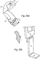
- Figure 20a shows the cover panel (CP) in the open position with a flexing latch arm (A) on the base plate or frame (CF) of the cover and a retaining member/clasp (B) on the underside of the cover panel (CP).
- Figure 20b shows how the clasp (B) engages with the tip of the latch arm (A) as the cover panel (CP) is closing.
- Figure 20c shows the clasp (B) and latch arm (a) fully engaged corresponding to the closed position of the cover panel (CP).
- Figure 20d shows a key (D) being inserted and located in its barrel prior to turning to release the latch arm (A).
- Figure 20e shows the movement of the key blades (E) against the latch arm (A) as the key (D) is being turned to release the latch arm (A) allowing the cover panel (CP) to open.
- This locking mechanism may be used with any of the embodiments previously described.
- FIGS 21a-e there is shown yet another locking mechanism for a detachable cover in which the cover frame (CF) is U-shaped to slide behind the faceplate (not shown) of a socket and be secured by the faceplate as described in our UK Patent No.2366457 .
- Figure 21a shows the cover panel (CP) in the open position with the latch arm (A) on the frame (CF) and the retaining member/clasp (B) on the cover panel (CP) as described previously.
- Figure 21b shows the latch arm (A) mounted on an axle and a torsion spring (E) arranged to bias the latch arm (A) to a vertical position engaging a stopper (F).
- Figure 21c shows the clasp (B) engaging the tip of the latch arm (A) as the cover panel (CP) closes to move the latch arm (A) against the spring bias.
- Figure 21d shows the clasp (B) and latch arm (A) engaged under the spring bias when the cover panel (CP) is in the closed position.
- Figure 21e shows a male key (D) inserted into a female barrel on the axle and rotational movement of the axle as the key (D) is being turned to release the latch arm (A) and allow the cover panel (CP) to open.
- Figure 21e also shows the axle with 'sprung tail' (G) as an alternative to the torsion spring (E).
- Figures 22a shows the cover panel (CP) in the open position with clasp (B) on the underside for engagement with the spring loaded latch arm (A) on the cover frame (CF) in the closed position.
- the cover panel (CP) also has a post (H) on the underside adjacent to the clasp (B) that is received in an opening (I) on the cover frame (CF) when the cover panel (CP) is closed.
- the cover panel (CP) is also provided with inwardly directed lugs (J) located around the periphery to co-operate with latching points (K) on the cover frame (CF) in the closed position to prevent additional security in the closed position.
- Figure 22b shows the combined torsion/compression spring (L) that biases the cover panel (CP) for rotational movement about the hinge axis towards the open position and for axial movement parallel to the hinge axis towards a locked position.
- the spring (L) biases the cover panel (CP) to the left as viewed in Figure 22a .
- the cover panel (CP) is not fully closed and on, further movement towards the closed position, the clasp (B) engages the latching arm (A) as described previously to secure the cover panel (CP) in the closed position.
- a double locking action is provided by engagement of the lugs (J) and clasp (B) on the cover panel (CP) with the latching points ((K) and latching arm (A) on the cover frame (CF).
- the cover panel (CP) In the closed position, the cover panel (CP) is prevented from being slid axially against the biasing of the spring (L) to release the engagement of the lugs(J) with the latching points (K) by engagement of a detent (M) with the cover panel (CP).
- Figure 22c shows release of the double latch to open the cover by means of a key (D).
- the key (D) has a pair of radial arms (D1,D2).
- the arm D1 engages the latch arm (A) on initial rotation of the key to release the clasp (B) on the cover panel (CP). This allows the cover panel (CP) to move away from the closed position sufficiently for the cover panel (CP) to clear the detent (M) while still prevented from moving to the open position by engagement of the lugs (J) with the latching points (K) around the perimeter of the cover panel (CP).
- a cam face on the other arm (D2) engages the post (H) on the underside of the cover panel (CP) to displace the cover panel (CP) sideways parallel to the hinge axis against the biasing of the spring (L) until the lugs (J) are clear of the latching points (K) allowing the cover panel (CP) to move freely to the open position under the biasing of spring (L).
- the lugs (J) and latching points (K) are misaligned so that the radiused edged contact each other on closing the cover panel (CP) as described previously.
- the double latching arrangement provides additional security against forcing of the cover panel (CP) in the closed position.
- Figures 23a-d show the application of the double latching arrangement of Figures 22a-c to the locking mechanism of Figures 21a-e in a detachable cover according to the present invention and again like reference numerals are used to indicate corresponding parts where appropriate.
- the cover frame (CF) has four sides to extend all the way around the perimeter of a double socket (not shown).
- the frame (CF) comprises a U-shaped member (CF1) that extends across the top and down both sides of the socket as shown in Figure 21a and a base member (CF2) that extends between and is releasably connected to the outer ends of the legs of the U-shaped member on each side of the frame.
- any suitable connection may be provided, for example interengageable mating formations (CF',CF") that clip together (see Figure 23d ).
- the frame (CF) can be assembled without removing the faceplate of the socket from the wall and arranged so that the interengageable formations are located behind the faceplate in the mounted position of the cover.
- the cover frame (CF) shown in Figure 22a may be of similar construction.
- the axle mounting the latch arm (A) is attached to the base of the cover frame (CF) by means of a threaded screw (N).
- N a threaded screw
- the latch arm (A) is released from the clasp (B) allowing the cover panel (CP) to open slightly to clear the detent (M).
- axle returns to its original position on removal of the key (H) allowing the lugs (J) and clasp (B) to engage the latching points (K) and latch arm (A) when the cover panel (CP) is next closed as described previously.
- Figure 23c shows the axle with a "sprung tail” (G) in place of the torsion spring (E) as described previously.
- Figures 24a-e show its application to the locking mechanism of Figures 16a-d .
- the centre prong (906) of the key (903) initially displaces the shutter (113) to allow entry of the prongs (114) to release the latch arms (112) enabling the cover panel (CP) to partially open in the direction of arrow A to clear the detent (not shown) blocking sideways movement of the cover panel in the closed position.
- the centre prong (906) engages the post (115) on the underside of the cover panel (CP) and moves the cover panel sideways parallel to the hinge axis until the perimeter lugs (not shown) clear the latching points (not shown) allowing the cover panel (CP) to move freely to the open position as described previously.
- Figures 25a & 25b show its application to the locking mechanism of Figures 13 to 15 .
- the centre prong of the key (903) again opens the apertures (904) allowing the outer prongs to release the detents (905) from the eyelets (700) to enable the cover panel to open partially and thereafter the centre prong engages the post (115) on cover panel to move the cover panel sideways to disengage the perimeter lugs (not shown) from the latching points (not shown) on the cover frame to allow the cover panel to move freely to the open position as described previously.
- the detent (M) on the cover frame (CF) to prevent sideways movement of the cover panel (CP) in the closed position is provided with an angled cam extension (M1) of triangular shape that co-operates with the perimeter edge of the cover panel (CP) as it is closed to move the panel sideways (to the left as viewed in Figure 26a ) on closing the cover panel (CP) to ensure the lugs (J) fully engage the latching points (K) in the closed position.
- the axial biasing provided by the compression/torsion spring (L) can be reduced with potential benefits by allowing spring torsion strength to open the cover panel (CP) to be optimised combined with improved spring life from reduced wear and degradation of the spring (L) in use.
- the above modification may be applied to any of the other double latching mechanisms described herein.
- a flexible latch arm (600) on the cover frame (not shown) is engageable with a clasp (not shown) on the underside of the cover panel (not shown) to secure the cover panel in the closed position.
- An axle (601) carries a cam shaped disc (602) and is rotated by insertion of a key (603) to cause a cam lobe (604) on the disc (602) to displace the latch arm (600) in the direction of the arrow (A) to release the clasp.
- This action may completely release the cover panel for movement to the open position or partially release the cover panel with a further action required to disengage additional latch means such as the perimeter latching points described above to fully release the cover panel.
- additional latch means such as the perimeter latching points described above to fully release the cover panel.
- the latch arm does not lie on the same axis or plane as the key barrel through which the key passes to engage the axle. In this way the latch arm (or other suitable latching means) is shielded within the cover and protected out of reach from instruments or tools which may be deployed in an attempt to gain unauthorised access to the cover.
- a flexible latch arm (500) on the cover frame (CF) is engageable with a clasp (501) on the cover panel (CP) to secure the cover panel (CP) in the closed position.
- the latch arm (500) is offset to one side of a two-prong hole (502) in the cover frame (CF) or a three prong hole if a shutter is employed as described previously to cover the hole (502) in the closed position.
- the latch arm (500) has an integral finger (503) that extends transversely and is aligned with the hole (502).
- the finger (502) is cylindrical and carries a sleeve (504) that is freely rotatable on the finger (502).
- a key (505) with two prongs (or three if a shutter is employed) is inserted through the hole (502) towards the finger (503).
- the prongs define a slot (507) in which the finger (503) is received.
- the slot (507) is tapered so that the prongs compress the sleeve (504) so that it grips the finger (503) allowing the latch arm (500) to be displaced to release the clasp (501). If an attempt is made to release the latch arm (500) by inserting a tool such as screwdriver into the hole (504) to move the finger (503), the tool will contact the sleeve (504) which rotates on the finger (503) preventing the application of a pushing force to displace the finger (503) to release the latch arm (500).
- a tool such as screwdriver
- the cover panel (CP) has a plurality of flexible latch arms (300) engageable with a retainer (301) on the cover frame (CF) to secure the cover panel (CP) in the closed position.
- the cover panel (CP) is provided with a profiled slot (302) into which a portion of each latch arm (300) extends.
- a key (not shown) having a profile matching that of the slot (302) can be slid lengthwise of the slot (302) in similar manner to a card operated "swipe" lock to cause the latch arms (300) to disengage the retainer (301) and release the cover frame (CF) for movement to the open position.
- the latch arms (300) automatically re-engage the retainer (301) when the cover panel (CP is next closed.
- the length of the slot (302) and the number of latch arms (300) can be chosen as desired.
- FIG. 30 there is illustrated application of the lockable cover of the invention to voice and data appliances such as telephones, facsimile machines and computers that are connected to telephone and data networks.
- a splitter device (1100) is connected to a standard telephone socket (1101) by way of a cable (1102).
- the splitter device is a modem (1100) with a splitter circuit, that is one circuit to carry voice and another circuit to carry data. It will be understood however that other splitter devices could be employed, for example a DSL filter.
- the modem (1100) is connected by a cable (1103) to a telephone/fax machine (1104) - the voice cable - and by a cable (1105) to a computer (1106) - the data cable.
- the user can choose whether to allow unsupervised connections to the telephone, fax via the telephone or voice cable (1103) and/or the Internet via the data cable (1105).
- the cable (1103) from the telephone (1104) can be inserted into the modem splitter and the lockable cover fitted to prevent connection of the cable (1105) for the computer (1106).
- connection to the internet may be provided by connecting the cable (1105) and use of the telephone/fax prevented by fitting the lockable cover without attaching the cable (1103).
- the lockable cover may be any of the types described herein ie a detachable accessory or an integral part of the frame and the lock can be any of the kinds described herein.
- the locking mechanisms for releasably securing the cover panel in the closed position are mechanically operable by means of a key or similar actuator device. It will be understood however, that the invention is not limited to such mechanical operation and that the cover could include a powered locking mechanism such as a mains or battery powered electrically operable locking mechanism.
- a cover (1200) for a double socket (not shown) comprises a frame (1201) for mounting between a faceplate of the socket and a wall mounting box as described previously.
- the frame (1201) has an upper part (1202) and a lower part (1203).
- the upper part (1202) is provided with a cover panel (1204) that is movable between a closed position shown in Figure 31 to conceal the socket and an open position shown in Figure 32 allowing access to the socket.
- the lower part (1203) is hollow and houses the locking mechanism (1205) for securing the cover panel (1204) in the closed position.
- the lower part (1203) is provided with a pair of recesses (1206) in the front face for passage of cable leads (not shown) connected to plugs (not shown) attached to the socket.
- the recesses (1206) are closed at the front edge of the lower part by cable tie plates (1207) that are a push fit in grooves (1208) to retain the cables in the recesses (1206).
- the upper edges of the tie plates (1207) are concealed by the cover panel (1204) in the closed position and the tie plates (1207) are retained in position by a rib (1209) on the underside of the cover panel (1204).
- the cable tie plates (1207) transfer the applied forces to the securely mounted frame (1200) which is able to withstand the loads. In this way, the application of loads to the plugs and/or cover panel (1204) such as may disconnect the plugs and/or force open the cover panel (1204) can be avoided.
- loads to the plugs and/or cover panel (1204) such as may disconnect the plugs and/or force open the cover panel (1204) can be avoided.
- a similar arrangement may be applied to any of the covers described herein.
- the locking mechanism (1205) includes a U-shaped latch member (1210) pivotally mounted within the lower part (1203) of the frame (1200).
- the latch member (1210) has a pair of latch arms (1211) and is pivotal between a latching position in which hooked ends (1211A) of the arms (1211) project through holes (1212) in the upper surface of the lower part (1203) and a release position in which the hooked ends (1211A) are withdrawn into the lower part (1203).
- the latch member (1210) is biased to the latching position by a spring (not shown) and is movable against the biasing to the release position by actuation of a solenoid operated piston rod (1213).
- the piston rod (1213) is movable between extended and retracted positions according to actuation of the solenoid.
- the solenoid may be powered by a battery or by connection to the mains via suitable transformer.
- the latch member (1210) In the retracted position, the latch member (1210) is biased to the latching position and a plate (1214) on the latch member (1210) contacts the end of the piston rod (1213). In this condition, the latch member (1210) can move away from the latching position in response to movement of the cover panel (1204) towards the closed position. In this way, the latch member (1210) automatically engages the rib (1209) on the underside of the cover panel (1204) when the cover panel (1204) returns to the closed position from the open position.
- the latch member (1210) is movable to the release position against the biasing of the spring by actuation of the solenoid to extend the piston rod (1213) causing the latch member (1210) to pivot to lower the hooked ends (1211A) and release the cover panel (1204) which moves to the open position under its spring biasing.
- the solenoid controlling the piston rod (1213) can be operated remotely by any suitable means such as by a radio signal or by an infra-red signal from an appropriate transmitter with a suitable sensor to receive the signal.
- the transmitter may be incorporated in a portable hand held device such as a key fob that may be programmed to operate more than one lockable cover, for example in installations in domestic or commercial environments where a plurality of lockable covers may be employed and control of access to some or all of these is required.
- a portable hand held device may also be programmed to control over lockable fixtures or items in the home or office to restrict access to authorised users.
- the latch member (1210) may also be operated manually by means of a key (1214) to allow the cover panel (1204) to be released in an emergency, for example if a power supply to the solenoid is interrupted.
- the key (1214) may be inserted through a hole (1215) in the side of the lower part (1203) to engage a shaft (1216) for rotating the latch member (1210).
- the engagement between the key (1214) and shaft (1216) may be by any suitable formations, preferably male and female.
- the key operation may include features from any of embodiments previously described to improve security and reduce the risk of unauthorised release of the cover panel (1204).
- embodiments with integral (built-in) cover and separate, detachable cover have a cover panel that is mounted for hinging movement between open and closed positions.
- a cover panel that opens and closes along a flat plane of movement, that is, by the action of sliding movement, rather than hinging movement.
- Such sliding cover panel may move up or down or from side to side and may either retract into the frame itself or protrude from the upper side, the lower side (or both upper and lower sides) or the left side, the right side (or both the left and right side) of the frame.
- the purpose of the sliding cover panel is to provide all the protection to plugs, sockets and switches afforded by previously described hinged cover panels whilst offering no additional obstruction away from the wall when in either the open or closed position.
- the cover panel opens in a flat plane of motion (either up or down or from side to side) such that no additional space away from the wall is required for the cover to operate successfully.
- a sliding cover panel as opposed to a hinged cover panel that swings outwards, is where obstructions created by leaving a hinged cover panel in the open position may prove hazardous.
- hazardous situations are areas where there is a lot of movement (such as a busy office) or where there are high risk or accident-prone groups nearby (such as in a nursery school or old peoples home), where an individual could suffer injury by tripping or falling over or onto such an open cover panel.
- Commercial premises with areas open to the general public may prefer a sliding cover panel as a means of reducing the likelihood accidents.
- the cover with sliding cover panel may be provided as a separate unit that locates behind the faceplate of an existing plug socket wall fixture or as an integral part of a plug socket fixture as described in the previous embodiments.
- a detachable cover (100) comprising a frame (101) and a sliding cover panel (102).
- the frame (101) is mountable on the wall (not shown) by locating inwardly turned lips (101a) behind the faceplate of a socket (not shown).
- the cover panel (102) comprises a pair of panel members (102A, 102B) slidably mounted between side walls of the frame (101). This is not essential and the panel (102) may comprise one or more panel members as desired.
- the panel members (102A,102B) are shown in a closed position in Figures 33 covering the faceplate.
- the panel members (102A,102B) are biased to an open position (not shown) allowing access to the faceplate of the socket by a spring (201) acting between the frame (101) and the lower panel member (102A).
- the lower panel member (102A) is secured in the closed position by a latch mechanism similar to that shown and described with reference to Figures 28a-c and like reference numerals are used to indicate corresponding parts.
- the operation of the latch mechanism will be understood from the description of Figures 28a-c and is not repeated.
- the cover panel members (102A,102B) are guided for sliding movement in inwardly facing grooves (101b) in the sidewalls of the frame (101) and the lower panel member (102A) is designed to "pick-up" the upper panel member (102B) as it moves to the open position under the biasing of the spring (201).
- cover panel (102) "concertinas" to reduce in size in the open position and can be confined within the frame (101).
- the number of panel members (102A, 102B) may be chosen as desired.
- the frame (101) has a base plate (205) with openings for passage of cable leads and cable ties (not shown) may be provided as described previously so that pulling forces applied to the cables are transferred to the frame (101) away from the cover panel (102).
- At least some embodiments not according to the invention provide a lockable cover that is "built-in" to the socket, either as an integral part thereof or separate but permanently secured thereto (otherwise referred to as the detachable accessory socket).
- the invention proposes a socket with integral lockable cover with a frame that is either formed integrally with the socket plate, or is formed separately and permanently attached to the socket plate, and a latchable cover panel hingedly secured to the frame so as completely to cover the switch or socket and any plug therein when closed.
- Such detachable accessory socket with integral cover may be used for new build and when adding sockets to an existing circuit or to replace an unprotected socket in an existing circuit.
- Other embodiments according to the invention provide a lockable cover that is detachable from the socket and can be fitted to an existing socket.
- At least some embodiments of the invention also provide double latching arrangements for securing the cover panel in the closed position that can be employed with detachable versions of the cover. Furthermore, some embodiments of the invention provide a detachable cover with a frame that extends around the perimeter of the socket plate and is held in place by the socket plate.
- a particular advantage of the latching mechanisms described herein is that they allow single handed operation both for opening and closing the cover panel.
- the cover panel is automatically latched on being pushed to the closed position and, where key-operated, rotation of the key can be sufficient to release fully the cover panel, even with those arrangements employing a double latch to secure the cover panel.
Landscapes
- Engineering & Computer Science (AREA)
- Computer Security & Cryptography (AREA)
- Connector Housings Or Holding Contact Members (AREA)
- Cookers (AREA)
- Switch Cases, Indication, And Locking (AREA)
- Installation Of Indoor Wiring (AREA)
- Fire-Detection Mechanisms (AREA)
- Driving Mechanisms And Operating Circuits Of Arc-Extinguishing High-Tension Switches (AREA)
- Road Signs Or Road Markings (AREA)
- Brushes (AREA)
- Casings For Electric Apparatus (AREA)
Abstract
Description
- This invention is concerned with detachable covers for a switch or a socket (and for a plug when in that socket) such as may be used for providing electricity or a telephone, video or data connection.
- In modern electrical systems as used in houses, offices and other buildings, electricity is delivered by cabling to various points around the building at which there are electric sockets with faceplates into which appliances to be powered using the electricity supply can be plugged. Such sockets may be unswitched or switched so that the power supply to appliances plugged into the sockets can be controlled without unplugging the appliance. Moreover, in a modern building there will be a technically similar system for providing communication channels - for telephone, television and computer.
- Each of the sockets will usually be of the type having an apertured terminal-carrying socket faceplate mountable on a recessed socket box itself flush mounted within a cavity in or on a wall. The apertures lead to the socket's terminals, disposed on the back of the plate and thus out of harm's way inside the box, and are shaped and sized to match the contact pins of the plug for which the socket is designed.
- Another type of socket commonly encountered, especially in electric power circuits, is the "extension socket" where a group of two or more individual sockets are arranged in a box-like carrier and connected by a single lead to a plug that plugs into a single wall-mounted socket (in this way a single such wall socket can, within reason, be "converted" into a plurality of sockets). Such an extension socket device normally has the appropriate plurality of apertured terminal-carrying socket plates mounted on a socket box. In principle, therefore, it is little different from a wall-mounted socket.
There are many reasons why it might be desirable to provide a cover over a socket, or over a plug when in place in that socket. One is to prevent small children from poking their fingers, their toys, or any available long thin object - such as a knitting needle or a screwdriver - into the plug pin apertures in the socket. Another reason is that much modern equipment is designed to be plugged in and left on and connected all the time - falling into this category are refrigerators, televisions (and video recorders) and Fax machines at one extreme, and computers (and their networks) and medical life support systems at the other - and sometimes it may be a minor disaster if the device is disconnected, unplugged or turned off. - The problem, as always, is how to achieve a cover that is both effective, securely hiding the switch, socket or plug from an unauthorised person and yet also relatively easy for an authorised person to remove in order to access the plug, or the socket and its switch.
- One solution for an empty socket is to insert into it an imitation plug with a shallow head that a child's fingers cannot easily grip. Such a solution does not help with the secondary problem of preventing a used socket being switched off, or having the plug removed from it. To deal with this problem, box-like covers that can be secured over the plug-carrying socket so as to prevent access to the plug are known. However, none of these covers is especially convenient - or, sometimes, terribly effective.
- Examples of detachable covers for sockets or switches are disclosed in
WO-A-02/13323 GB-A-2287138 US-A-4163882 . - It is an object of the present invention to provide a detachable cover that is simpler and easier to use whilst at the same time providing the required secure protection.
- Thus, according to the present invention, there is provided a detachable cover for a socket or switch as defined in claim 1. Preferred features of the detachable cover are the subject of the dependent claims.
- The invention has application to sockets with pin receiving apertures for a plug where it may be desirable to conceal a front surface of the face plate provided with pin receiving apertures for a plug and/or a switch, for example to prevent equipment being inadvertently switched off.
- For UK sockets (and switches), the faceplate is traditionally of rectangular shape and the frame may be of U-shape that can be slid into place from above to extend on three sides of the faceplate leaving an opening in the other side for passage of the lead of a plug(s) when the cover is secured in position and the plug(s) is shrouded by the cover panel in the closed position. Typically, the frame extends across the top and down both sides of the faceplate leaving the opening at the bottom.
- With this arrangement, pulling forces applied to the cable may be transferred to the latch(es) via the cover panel and this could result in the cover panel being forced open. The invention therefore provides a frame that extends on all four sides of the faceplate with the opening being arranged so that pulling forces applied to a cable passing through the opening is transferred to the frame which is securely mounted and can better withstand the forces. In this way, the pulling forces are not applied to the latches.
- The transfer of forces to the frame may be achieved by means of a detachable cable tie that can be fitted after locating the cable in the opening. In this way the plug does not have to be removed from the cable in order to feed the cable through the opening. The cable tie may also help to prevent the plug being disconnected by pulling the cable while the cover panel is in the closed position.
- In order that the frame can be fitted to extend on four sides of the faceplate without completely removing the faceplate and disconnecting the electrical connections, the frame comprises at least two frame members that are arranged to extend around the faceplate and located behind the faceplate so as to be secured by the faceplate. The frame members comprise a U-shaped frame member that is slid into place to extend across the top and down both sides of the faceplate and a base frame member that is positioned to extend across the bottom of the faceplate and attached at each end to the U-shaped frame member. For example, the base frame member may be provided with formations at each end that engage mating formations of the U-shaped frame member on both sides of the faceplate. Preferably, the frame members are arranged so that the engaged portions can be located behind the faceplate so as to inhibit disconnection when the
cover is secured in position. The base frame member may be provided with at least one opening for passage of cable lead(s) and at least one tie member so that pulling forces applied to the cable are transferred to the frame and away from the cover member. - Embodiments of the invention in its various aspects will now described in more detail by way of illustration only, with reference to the accompanying diagrammatic drawings in which:
-
Figures 1, 2 and 3 show views of a conventional electric plug, socket box and plate mounted in a wall; -
Figures 4 and 5 show front and perspective views of the faceplate of a single socket with integral (built-in) cover not according to the invention with the cover panel removed; -
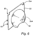
Figure 6 shows a perspective view of the cover panel of the socket shown inFigures 4 and 5 separate from the frame; -
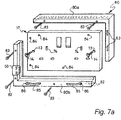
Figures 7a &7b show views of an interlocking frame for a double socket with integral (built-in) cover not according to the invention; -
Figure 8 shows a view of an interlocking frame for a freestanding multi-outlet socket with integral (built-in) cover not according to the invention; -
Figure 9 shows a front view of a double socket with integral (built-in) cover not according to the invention having side hinged cover panels shown in the closed position; -
Figure 10 shows a front view of the socket ofFigure 9 with the cover panels removed; -
Figure 11 shows a rear perspective view, to an enlarged scale, of one of the cover panels shown inFigure 9 ; -
Figures 12a & 12b show a modified version of a single socket with integral (built-in) cover not according to the invention having side hinged cover panels for use with plugs that are centrally mounted; -
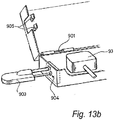
Figures 13a &13b show details of a double socket cover with integral (built-in) cover not according to the invention with a top hinged cover panel shown in the open position and a key operated locking mechanism having a three pronged key; -
Figures 14a & 14b show details of the locking mechanism; -
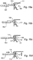
Figures 15a &15b show the operation of the locking mechanism; -
Figures 16a -d show details of an alternative locking mechanism for the cover ofFigures 13a &13b ; -
Figure 17 shows details of an alternative locking mechanism for use in a cover like that ofFigures 13a &13b ; -
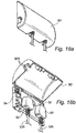
Figures 18a & 18b show perspective views of an alternative socket with integral (built-in) cover not according to the invention in the closed and open positions; -
Figures 19 shows a faceplate incorporating a night light, air freshener and fuse holder for a socket with integral (built-in) cover not according to the invention with the cover panel detached for clarity; -
Figures 20a -e show an alternative type of locking mechanism; -
Figures 21a -e show yet another type of locking mechanism in a detachable cover not according to the invention; -
Figures 22a -c show a modification to the locking mechanism ofFigures 20a-e in a detachable cover not according to the invention; -
Figures 23a -d show a modification to the locking mechanism ofFigures 21a-e in a detachable cover according to the invention; -
Figures 24a -e show a modification to the locking mechanism ofFigures 16a-d ; -
Figures 25a &25b show a modification to the locking mechanism of 13 to 15; -
Figures 26a & 26b show a modification to the locking mechanism ofFigures 22a-c in a detachable cover according to the invention; -
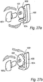
Figures 27a & 27b show an alternative form of locking mechanism; -
Figures 28a -c show another form of locking mechanism; -
Figure 29 shows another type of locking mechanism; -
Figure 30 shows another application of the invention; -
Figure 31 shows a perspective view of another detachable lockable cover according to the invention with the cover panel in the closed position; -
Figure 32 is an exploded perspective view of parts of the cover shown inFigure 31 with the cover panel in the open position; -
Figure 33 shows a front perspective view of a detachable lockable cover according to the invention with a sliding cover panel; and -
Figure 34 shows an exploded isometric rear view of the cover shown inFigure 33 . - Referring first to
Figures 1 to 3 , a conventional plug/socket combination is shown (to avoid confusing complexity, the Figures do not show any of the wires leading to the socket, nor do they show the details of the internal structure of the terminals). Mounted in a hole in the wall (11) is a metal socket box (12) with an inwardly directed front flange (13) onto which a socket plate (17) is affixed by screw-headed bolts (14) engaging with threaded holes (15). The socket plate (17) contains the usual plug pin holes (18) - earth/ground, live, neutral - into which the pins of the plug (19) fit. - With reference now to
Figures 4 to 6 , a socket with integral (built-in) cover not according to the invention is shown comprising the combination of a socket faceplate (20) with integral frame (21) and a lockable cover panel (22). The faceplate (21) is mountable on a wall (not shown) by way of the screw headed bolts (14) for securing the face plate (20) to a mounting box (not shown) either recessed in the wall or surface mounted. - The frame (21) is arranged at the perimeter of the faceplate (20) and extends across the top and bottom. The cover panel (22) is hingedly secured to the frame (21) by a hinge pin/socket arrangement (24a,24b) for hinging movement about a vertical axis at one side of the faceplate (20) (the tight as viewed in the drawing). The panel (22) is swingable between a closed position, where it completely covers and encloses the front surface of the faceplate (17) and any plug therein, and an open position, where it is clear therefrom, allowing access thereto. The hinge mechanism is biased (in a manner not shown here) so that when the panel (22) is released it will spring open by itself.
- In the embodiment shown, the frame (21) is formed integrally with the face plate (17) for example by moulding and the socket is quite bulky. On the side distant from the hinge pin/socket (24a,24b), the faceplate (17) contains internal latch means for holding the cover panel (22) closed. As can seen, the panel (21) has projecting latch pins (64) that pass into the faceplate (17) via corresponding latch holes (65) to engage with the latch means until released by a key (not shown) inserted into two keyholes (66) in the side of the frame (21) to allow the panel (22) to move to the open position under its spring biasing. The latch means is self-latching to secure automatically the cover panel (22) on being moved from the open position to the closed position.
- As will be clear from
Figures 4 to 6 , the frame (21) and the cover panel (22) are shaped, especially at the corners (61), to fit one to the other so as to form a flush front surface that has no protruding edges for a child's finger nails to get under in an attempt to prise the two apart. -
Figures 7a and7b show an interlocking frame (80) for a faceplate (17) of a double socket that is secured to a wall mounting box (not shown) by screws (14) that extend through holes (13) in the faceplate (17). - The perimeter of the socket faceplate (17) is enclosed within the frame (80). The inner perimeter of the frame (80) has within it two parallel lips (82) of flexible material such as plastic or rubber arranged at an angle perpendicular to the front surface of the frame (80) and running along the entire perimeter of the inside of the frame (80). These lips (82) grip the faceplate (17) as it is retained between the lips (82) as a snug fit.
- The frame (80) is assembled first by the interlocking of the
frame parts 80a,80b and lips (82) around the faceplate (17), and then by the application of flat-ended screw bolts (83) that extend through the outer edge of the frame (80) and into holes (84) in the surface of faceplate (17). The screw bolts (83) are of a non-removable, tamper-proof type such that the frame (80) is permanently secured to faceplate (17). In this way, the frame (80) is integral (built-in) to the faceplate (17). - Cable ties (85) are attached by being threaded from the inside of the frame part (80b) through apertures (86) from the underside of the hollow frame part (80b) prior to the frame being slid into place around the faceplate (17). The cable ties (85) are arranged to receive the leads of plugs (not shown) inserted in the sets of pin receiving holes (74) so that pulling forces applied to the leads are transferred to the frame (80). Alternatively, the cable ties (85) can be moulded as a permanent part of the perimeter frame (80).
- Hinges (63) for the cover panel are provided on one side edge and latch means (66) is provided on the opposite side edge for securing the panel in the closed position. In this way, the cover panel (not shown) opens with a hinging motion from left to right on the side hinges (63). The latch means (66) may be of any type described herein to secure the cover panel in the closed position.
-
Figure 8 shows an interlocking frame (70) for a freestanding multipoint extension socket or strip adaptor (81). The frame (70) is assembled around a base (71) of the multipoint socket (81) and secured in similar manner to the frame (80) described above to become an integral (built-in) part of the frame (80). - The frame (70) has cable ties (85) that are threaded through holes in the bottom edge of the frame (70) and receive the leads of plugs (not shown) inserted in the sets of pin receiving holes (74) so that pulling forces applied to the leads are transferred to the frame (70).
- A cover panel (not shown) is connected to the frame (70) by hinges (63) along the top edge of the frame (70) and is secured in the closed position by latch means (not shown) at the bottom edge of the frame (70). In this way, the panel lifts away from the plugs on being opened. The latch means may be of any type described herein to secure the cover panel in the closed position.
-
Figures 9 to 11 show another embodiment of a double socket (41) with integral (built-in) cover (40). The cover (40) has a frame (42) that is formed integrally with or permanently secured around the periphery of the socket (41) as described previously and has cable ties (42a) for the cable leads of plugs (not shown) inserted in the pin receiving holes (43) of the socket (41). - The frame (42) has hinges (44) on both vertical side edges that mount a pair of cover panels (45) for hinging movement between a closed position shown in
Figure 9 in which the panels (45) meet at the centre of the socket (41) and an open position (not shown) in which the panels (45) move outwards with a hinging motion from the centre to the opposed side edges. - The panels (45) are secured in the closed position by a latch mechanism (46) positioned centrally of the top edge of the frame (42) and operable by a key (not shown) inserted through holes (47) in the upper surface of the frame (42). The panels (45) are provided with arcuate sections that provide clearance to accommodate a plug inserted in the socket when the panels (45) are closed. The panels (45) may be secured by a common latch mechanism (46) to be released simultaneously when the key is inserted. Alternatively, each panel (45) may be secured by a separate latch mechanism allowing the panels to be opened/closed individually.
-
Figures 12a and 12b show a modification to the cover (40) suitable for use with plug and socket systems in which the cable extends from the centre of the socket, rather than at the bottom. Such systems are commonly in use throughout America and Europe. For convenience like reference numerals are used to indicate parts corresponding toFigures 9 to 11 . -
Figures 13a and13b show details of another embodiment of a double socket (91) with integral (built-in) cover (90) not according to the invention. The double socket (91), which is a switched socket, has a socket plate (92) having two sets of socket holes (not visible) in each of which is received a standard plug (93) with its attached cable (93A). The socket plate (92) is attached (by screw-headed bolts, not shown) to a mounting box (not visible) mounted in a recess in the wall (not shown). - Surrounding the socket plate (92) is the frame (94) for the cover (90). The frame (94) is formed integrally with or is permanently secured to the socket plate (92) as described previously. The frame (94) has an upstanding perimeter wall (96) that is apertured at (96A) to allow the plug cables (93A) to pass through. The cover (90) has a cover panel (98) hinged by a pin/socket mechanism (99) to the frame (94) along the upper (as viewed) edge of the
socket plate 92. The cover panel (98) is biased by a spring (901) towards the open position. - A lock mechanism (902) is mounted internally of the frame (94) on the left (as viewed) hand side of the perimeter wall of the frame (94) into which a three-pronged key (903) can be inserted via suitably-shaped apertures (904) in the perimeter wall of the frame (94).
- With reference now also to
Figures 14a and 14b , the cover panel (98) is provided with two pin detents (905) that project from the inner surface of the cover panel (98) and engage with retaining apertures (700), or 'flexing eyelets' to secure the cover panel (98) in the closed position. - As best shown in
Figures 15a and15b , the eyelets (700) are mounted on retaining hinges (701) within and perpendicular to the direction of insertion of the three-pronged key (903).Figure 15a shows the cover panel detents (905) engaged with the eyelets (700) rendering the cover locked. The key apertures (904) are closed in the locked condition by flaps (906).Figure 15b shows the key (903) moving along the lock shaft where the centre prong opens the apertures and the outer prongs cause the body of the eyelets (700) to rotate in a counter direction sufficient to disengage the cover panel detents (905) from the eyelets (700) allowing the cover panel (98) to move to the open position under the biasing of the spring (901) to allow access to the socket switches and any plugs inserted in the socket.. - With reference now to
Figures 16a-d , an alternative locking mechanism (902) is shown in which like reference numerals are used to indicate corresponding parts. In this arrangement, the tips (111) of the detents (905) on the underside of the cover panel (98) hook under an inner lip (112) on the side wall of the frame (94) to retain the cover panel (98) in the closed position (seeFigure 16c ). In this condition, a spring-loaded shutter (113) blocks the apertures (904) to prevent a tool being inserted to release the detents (905). - As the three pronged key (903) is inserted into the apertures (904) of the locking mechanism, the centre, longer prong (906) engages the shutter (113) and forces shutter (113) down against its biasing to open the apertures (904) allowing access to the mechanism per se. As the key (903) penetrates further so the two side prongs (114) move on through the now unguarded gap into contact with the tips (111) of the detents (905) and push them away from the lip (112) thus releasing the cover panel (98) and allowing the spring (901) to drive the cover panel (98) to the open position.
- If the key (903) is then removed, the sliding shutter (113) slides shut, blocking off the keyhole apertures (904) and, when the
panel 98 is next pushed shut, the tips (111) of the detents (905) click into place under the lip (112) and the cover panel (98) is held securely in the closed position. - With reference now to
Figures 17a-c , there is shown an alternative locking mechanism for use with the covers described herein. The locking mechanism has two circular discs (951) that are arranged in position between seared release pins (211) or T-shaped rocker cams (221) where fitted, and spring-loaded shutter (213). - The internal discs (951) have solid faces (952) save for a hole machined into the centre of each disc (953) to create a fixing point for an axle type attachment (not shown) that allows the disc to turn, and a further hole (954) machined into the face (952), the shape, positioning and size of which allows a single prong of either the 2 or 3 pin key (903) to pass through unimpeded.
- Each internal disc (951) is serrated on its outer perimeter (955), so that they may engage with and be rotated by a controlling disc (956) - see
Figure 17b . The controlling discs (956) are serrated on their inner perimeter (957) and are numbered on their outer perimeter (958) - seeFigure 17c . - The outer perimeter (958) of each controlling disc (956) protrudes through the casing of the key barrel (959) at points just to the outside of each keyhole aperture (904). When the controlling discs (956) are turned on their axis the numbers on the perimeters are visible to the user.
- Turning the controlling discs (956) causes the internal discs (951) to move around too. The mechanism functions such that the numbers on each controlling disc (956) can be aligned in combination to a predetermined point or marker (for example machined onto the outside of the cover) whereby the holes (954) on each internal disc (951) correspondingly and simultaneously align inside the barrel (959) with the holes (904) for inserting a two prong key or, where the shutter (213) is provided, a three prong key to displace the shutter (213) for passage of the other two prongs to make contact with the mechanism to release the cover panel (not shown) so that it may open. Unless the discs (951) are arranged correctly in combination, the passage for the key prongs to travel along the barrel (959) is blocked and the cover panel remains locked. It will be understood that the number of latches and discs may be altered as desired for use with a key having an appropriate number of prongs.
- Referring now to
Figures 18a & 18b , an alternative double socket with integral (built-in) cover is shown in both the closed and open positions. For convenience, the same reference numerals are used to indicate parts corresponding toFigures 13a &13b . Though visually somewhat different, conceptually this embodiment is similar and the operation will be understood from the description of previous embodiments. - Turning now to
Figure 19 , there is shown an embodiment of a single socket with integral (built-in) cover not according to the present invention with the cover panel removed for clarity and incorporating features providing the socket with added functionality. Where convenient, like reference numerals are used to indicate parts already described. - The socket face plate (17) and the mounting box (not shown) to which it is attached by screws (14) incorporate additional wiring (not shown) and on/off push button switches (961,962) to facilitate the function and control of a powered bulb (960) for a night light located across and close to the top of the faceplate (17).
- The light can project its beam through either a translucent cover panel (not shown) or through a slot cut into a solid (opaque) cover panel (not shown). The switches (961,962) for the night-light are located on the faceplate (17) such that they are accessible only when the safety cover panel is open.
- An L-shaped heat activated scented air freshener (966) is shaped and sized to fit exactly a slot (964) located along the top edge of the cover frame surrounding the faceplate (17). The outer face (965) of the air freshener (966) is perforated with holes to allow scent from below to pass up through the holes.
- The part of the air freshener (966) that drops into the slot (964) is positioned so that at least one face is located close to a suitable heat source - in this case the night-light (960) - and carries self adhesive strips of an absorbent, fire proof material (967) impregnated with scented liquid which, when subjected to a small amount of heat applied nearby, causes the liquid to evaporate and the air about it to perfume.
- All but the open top of the slot (964) is sealed to be water tight from the remainder of the socket. The slot (964) may be located in front of the hinges (not shown), and thereby inside the cover panel, or behind the hinges and therefore outside of the cover panel.
- As shown, a hinged door (972) is also provided along one side of the socket/faceplate frame for a hollow fuse compartment (970) and dispenser (971). The inside of the door (972) has moulded or attached retaining clips (971). Each clip (971) is designed and capable of holding one standard electric fuse in the vertical or horizontal position.
- As will be understood from the description of previous embodiments, a cover panel is hinged to the faceplate for pivotal movement between open and closed positions and has detents that are received in holes (904) in the closed position to engage latch means (not shown) to secure the panel in the closed position. The latch means is released by a key and the panel is biased to the open position as already described for other embodiments.
- Referring now to
Figures 20a-e there is shown another locking mechanism for securing a cover panel (CP) in a closed position. The cover panel (CP) may be part of an integral (built-in) cover as already described or a separate detachable cover of the type described later herein or in our earlierUK Patent No. 2366457 -
Figure 20a shows the cover panel (CP) in the open position with a flexing latch arm (A) on the base plate or frame (CF) of the cover and a retaining member/clasp (B) on the underside of the cover panel (CP).Figure 20b shows how the clasp (B) engages with the tip of the latch arm (A) as the cover panel (CP) is closing.Figure 20c shows the clasp (B) and latch arm (a) fully engaged corresponding to the closed position of the cover panel (CP).Figure 20d shows a key (D) being inserted and located in its barrel prior to turning to release the latch arm (A).Figure 20e shows the movement of the key blades (E) against the latch arm (A) as the key (D) is being turned to release the latch arm (A) allowing the cover panel (CP) to open. This locking mechanism may be used with any of the embodiments previously described. - Referring now to
Figures 21a-e , there is shown yet another locking mechanism for a detachable cover in which the cover frame (CF) is U-shaped to slide behind the faceplate (not shown) of a socket and be secured by the faceplate as described in ourUK Patent No.2366457 -
Figure 21a shows the cover panel (CP) in the open position with the latch arm (A) on the frame (CF) and the retaining member/clasp (B) on the cover panel (CP) as described previously.Figure 21b shows the latch arm (A) mounted on an axle and a torsion spring (E) arranged to bias the latch arm (A) to a vertical position engaging a stopper (F).Figure 21c shows the clasp (B) engaging the tip of the latch arm (A) as the cover panel (CP) closes to move the latch arm (A) against the spring bias.Figure 21d shows the clasp (B) and latch arm (A) engaged under the spring bias when the cover panel (CP) is in the closed position.Figure 21e shows a male key (D) inserted into a female barrel on the axle and rotational movement of the axle as the key (D) is being turned to release the latch arm (A) and allow the cover panel (CP) to open.Figure 21e also shows the axle with 'sprung tail' (G) as an alternative to the torsion spring (E). - Referring now to
Figures 22a-c ,there are shown modifications to the cover and locking mechanism ofFigures 20a-e . For convenience, like reference numerals are used to indicate corresponding parts where appropriate. -
Figures 22a shows the cover panel (CP) in the open position with clasp (B) on the underside for engagement with the spring loaded latch arm (A) on the cover frame (CF) in the closed position. The cover panel (CP) also has a post (H) on the underside adjacent to the clasp (B) that is received in an opening (I) on the cover frame (CF) when the cover panel (CP) is closed. The cover panel (CP) is also provided with inwardly directed lugs (J) located around the periphery to co-operate with latching points (K) on the cover frame (CF) in the closed position to prevent additional security in the closed position. -
Figure 22b shows the combined torsion/compression spring (L) that biases the cover panel (CP) for rotational movement about the hinge axis towards the open position and for axial movement parallel to the hinge axis towards a locked position. When the cover panel (CP) is in the open position, the spring (L) biases the cover panel (CP) to the left as viewed inFigure 22a . On closing the cover panel (CP) radiused edges of the lugs (J) contact radiused edges of the latching points (K) to move the cover panel (CP) to the right against the biasing of the spring (L) until the lugs (J) enter the latching points (K) allowing the cover panel (CP) to slide to the left and engage the lugs (J) with the latching points (K) to prevent the cover panel (CP) opening. - In this condition, the cover panel (CP) is not fully closed and on, further movement towards the closed position, the clasp (B) engages the latching arm (A) as described previously to secure the cover panel (CP) in the closed position. In this way, a double locking action is provided by engagement of the lugs (J) and clasp (B) on the cover panel (CP) with the latching points ((K) and latching arm (A) on the cover frame (CF). In the closed position, the cover panel (CP) is prevented from being slid axially against the biasing of the spring (L) to release the engagement of the lugs(J) with the latching points (K) by engagement of a detent (M) with the cover panel (CP).
-
Figure 22c shows release of the double latch to open the cover by means of a key (D). The key (D) has a pair of radial arms (D1,D2). The arm D1 engages the latch arm (A) on initial rotation of the key to release the clasp (B) on the cover panel (CP). This allows the cover panel (CP) to move away from the closed position sufficiently for the cover panel (CP) to clear the detent (M) while still prevented from moving to the open position by engagement of the lugs (J) with the latching points (K) around the perimeter of the cover panel (CP). - On continued rotation of the key (D), a cam face on the other arm (D2) engages the post (H) on the underside of the cover panel (CP) to displace the cover panel (CP) sideways parallel to the hinge axis against the biasing of the spring (L) until the lugs (J) are clear of the latching points (K) allowing the cover panel (CP) to move freely to the open position under the biasing of spring (L).
- In the open position, the lugs (J) and latching points (K) are misaligned so that the radiused edged contact each other on closing the cover panel (CP) as described previously. As will be appreciated, the double latching arrangement provides additional security against forcing of the cover panel (CP) in the closed position.
-
Figures 23a-d show the application of the double latching arrangement ofFigures 22a-c to the locking mechanism ofFigures 21a-e in a detachable cover according to the present invention and again like reference numerals are used to indicate corresponding parts where appropriate. - As shown in
Figure 23a the cover frame (CF) has four sides to extend all the way around the perimeter of a double socket (not shown). The frame (CF) comprises a U-shaped member (CF1) that extends across the top and down both sides of the socket as shown inFigure 21a and a base member (CF2) that extends between and is releasably connected to the outer ends of the legs of the U-shaped member on each side of the frame. - Any suitable connection may be provided, for example interengageable mating formations (CF',CF") that clip together (see
Figure 23d ). The frame (CF) can be assembled without removing the faceplate of the socket from the wall and arranged so that the interengageable formations are located behind the faceplate in the mounted position of the cover. The cover frame (CF) shown inFigure 22a may be of similar construction. - As shown in
Figure 23b , the axle mounting the latch arm (A) is attached to the base of the cover frame (CF) by means of a threaded screw (N). On initial rotation of the axle by means of a key (D) with the cover panel (CP) in the closed position, the latch arm (A) is released from the clasp (B) allowing the cover panel (CP) to open slightly to clear the detent (M). - On continued rotation of the key (D) the axle moves axially due to the threaded mounting to engage the post (H) to move the cover panel (CP) sideways parallel to the hinge axis until the lugs (J) clear the latching points (K) around the perimeter of the cover panel (CP) allowing the cover panel (CP) to move freely to the open position.
- The axle returns to its original position on removal of the key (H) allowing the lugs (J) and clasp (B) to engage the latching points (K) and latch arm (A) when the cover panel (CP) is next closed as described previously.
Figure 23c shows the axle with a "sprung tail" (G) in place of the torsion spring (E) as described previously. - The application of the double latching described above with reference to the locking mechanisms of
Figures 22 and23 can be applied to the other versions of locking mechanism described herein. -
Figures 24a-e show its application to the locking mechanism ofFigures 16a-d . As shown, the centre prong (906) of the key (903) initially displaces the shutter (113) to allow entry of the prongs (114) to release the latch arms (112) enabling the cover panel (CP) to partially open in the direction of arrow A to clear the detent (not shown) blocking sideways movement of the cover panel in the closed position. On further insertion of the key, the centre prong (906) engages the post (115) on the underside of the cover panel (CP) and moves the cover panel sideways parallel to the hinge axis until the perimeter lugs (not shown) clear the latching points (not shown) allowing the cover panel (CP) to move freely to the open position as described previously. -
Figures 25a &25b show its application to the locking mechanism ofFigures 13 to 15 . As shown, the centre prong of the key (903) again opens the apertures (904) allowing the outer prongs to release the detents (905) from the eyelets (700) to enable the cover panel to open partially and thereafter the centre prong engages the post (115) on cover panel to move the cover panel sideways to disengage the perimeter lugs (not shown) from the latching points (not shown) on the cover frame to allow the cover panel to move freely to the open position as described previously. - Referring now to
Figures 26a & 26b , there is shown a modification to the double latching locking mechanism of the detachable cover shown inFigures 23a-d . In this embodiment, the detent (M) on the cover frame (CF) to prevent sideways movement of the cover panel (CP) in the closed position is provided with an angled cam extension (M1) of triangular shape that co-operates with the perimeter edge of the cover panel (CP) as it is closed to move the panel sideways (to the left as viewed inFigure 26a ) on closing the cover panel (CP) to ensure the lugs (J) fully engage the latching points (K) in the closed position. - With this arrangement, the axial biasing provided by the compression/torsion spring (L) can be reduced with potential benefits by allowing spring torsion strength to open the cover panel (CP) to be optimised combined with improved spring life from reduced wear and degradation of the spring (L) in use. The above modification may be applied to any of the other double latching mechanisms described herein.
- Turning now to
Figures 27a & 27b , there is shown another variant of the locking mechanisms described herein. In this embodiment, a flexible latch arm (600) on the cover frame (not shown) is engageable with a clasp (not shown) on the underside of the cover panel (not shown) to secure the cover panel in the closed position. An axle (601) carries a cam shaped disc (602) and is rotated by insertion of a key (603) to cause a cam lobe (604) on the disc (602) to displace the latch arm (600) in the direction of the arrow (A) to release the clasp. - This action may completely release the cover panel for movement to the open position or partially release the cover panel with a further action required to disengage additional latch means such as the perimeter latching points described above to fully release the cover panel. With this arrangement, the latch arm does not lie on the same axis or plane as the key barrel through which the key passes to engage the axle. In this way the latch arm (or other suitable latching means) is shielded within the cover and protected out of reach from instruments or tools which may be deployed in an attempt to gain unauthorised access to the cover.
- Referring now to
Figures 28a-c , there is shown yet another variant of the locking mechanism described herein. In this embodiment, a flexible latch arm (500) on the cover frame (CF) is engageable with a clasp (501) on the cover panel (CP) to secure the cover panel (CP) in the closed position. The latch arm (500) is offset to one side of a two-prong hole (502) in the cover frame (CF) or a three prong hole if a shutter is employed as described previously to cover the hole (502) in the closed position. - The latch arm (500) has an integral finger (503) that extends transversely and is aligned with the hole (502). The finger (502) is cylindrical and carries a sleeve (504) that is freely rotatable on the finger (502). A key (505) with two prongs (or three if a shutter is employed) is inserted through the hole (502) towards the finger (503).
- The prongs define a slot (507) in which the finger (503) is received. The slot (507) is tapered so that the prongs compress the sleeve (504) so that it grips the finger (503) allowing the latch arm (500) to be displaced to release the clasp (501). If an attempt is made to release the latch arm (500) by inserting a tool such as screwdriver into the hole (504) to move the finger (503), the tool will contact the sleeve (504) which rotates on the finger (503) preventing the application of a pushing force to displace the finger (503) to release the latch arm (500).
- Referring now to
Figure 29 a still further version of a locking mechanism is shown. In this embodiment, the cover panel (CP) has a plurality of flexible latch arms (300) engageable with a retainer (301) on the cover frame (CF) to secure the cover panel (CP) in the closed position. The cover panel (CP) is provided with a profiled slot (302) into which a portion of each latch arm (300) extends. - A key (not shown) having a profile matching that of the slot (302) can be slid lengthwise of the slot (302) in similar manner to a card operated "swipe" lock to cause the latch arms (300) to disengage the retainer (301) and release the cover frame (CF) for movement to the open position. The latch arms (300) automatically re-engage the retainer (301) when the cover panel (CP is next closed. The length of the slot (302) and the number of latch arms (300) can be chosen as desired.
- Referring now to
Figure 30 , there is illustrated application of the lockable cover of the invention to voice and data appliances such as telephones, facsimile machines and computers that are connected to telephone and data networks. - A splitter device (1100) is connected to a standard telephone socket (1101) by way of a cable (1102). In this embodiment, the splitter device is a modem (1100) with a splitter circuit, that is one circuit to carry voice and another circuit to carry data. It will be understood however that other splitter devices could be employed, for example a DSL filter. The modem (1100) is connected by a cable (1103) to a telephone/fax machine (1104) - the voice cable - and by a cable (1105) to a computer (1106) - the data cable.
- By deploying a lockable cover (not shown) such as described herein over the modem (1100), the user can choose whether to allow unsupervised connections to the telephone, fax via the telephone or voice cable (1103) and/or the Internet via the data cable (1105). Thus, if the user wishes to ensure only the telephone (1104) remains connected, then the cable (1103) from the telephone (1104) can be inserted into the modem splitter and the lockable cover fitted to prevent connection of the cable (1105) for the computer (1106). Similarly, connection to the internet may be provided by connecting the cable (1105) and use of the telephone/fax prevented by fitting the lockable cover without attaching the cable (1103).
- This solution is desirable for parents or businesses who wish to control access to any combination of these appliances and the consequences that may arise from unsupervised usage. Using a simple lockable cover obviates the need for electronic programming of devices, such as installing software or configuring passwords to control Internet access from a computer. The computer or data device functions are unaffected, with the exception of data exchange through the Internet modem.
- The lockable cover may be any of the types described herein ie a detachable accessory or an integral part of the frame and the lock can be any of the kinds described herein.
- As described thus far, the locking mechanisms for releasably securing the cover panel in the closed position are mechanically operable by means of a key or similar actuator device. It will be understood however, that the invention is not limited to such mechanical operation and that the cover could include a powered locking mechanism such as a mains or battery powered electrically operable locking mechanism.
- One such arrangement is shown in
Figures 31 and32 , where a cover (1200) for a double socket (not shown) comprises a frame (1201) for mounting between a faceplate of the socket and a wall mounting box as described previously. - The frame (1201) has an upper part (1202) and a lower part (1203). The upper part (1202) is provided with a cover panel (1204) that is movable between a closed position shown in
Figure 31 to conceal the socket and an open position shown inFigure 32 allowing access to the socket. - The lower part (1203) is hollow and houses the locking mechanism (1205) for securing the cover panel (1204) in the closed position. The lower part (1203) is provided with a pair of recesses (1206) in the front face for passage of cable leads (not shown) connected to plugs (not shown) attached to the socket.
- The recesses (1206) are closed at the front edge of the lower part by cable tie plates (1207) that are a push fit in grooves (1208) to retain the cables in the recesses (1206). The upper edges of the tie plates (1207) are concealed by the cover panel (1204) in the closed position and the tie plates (1207) are retained in position by a rib (1209) on the underside of the cover panel (1204).
- In use, if the cables are pulled, the cable tie plates (1207) transfer the applied forces to the securely mounted frame (1200) which is able to withstand the loads. In this way, the application of loads to the plugs and/or cover panel (1204) such as may disconnect the plugs and/or force open the cover panel (1204) can be avoided. A similar arrangement may be applied to any of the covers described herein.
- The locking mechanism (1205) includes a U-shaped latch member (1210) pivotally mounted within the lower part (1203) of the frame (1200). The latch member (1210) has a pair of latch arms (1211) and is pivotal between a latching position in which hooked ends (1211A) of the arms (1211) project through holes (1212) in the upper surface of the lower part (1203) and a release position in which the hooked ends (1211A) are withdrawn into the lower part (1203).
- The latch member (1210) is biased to the latching position by a spring (not shown) and is movable against the biasing to the release position by actuation of a solenoid operated piston rod (1213). The piston rod (1213) is movable between extended and retracted positions according to actuation of the solenoid. The solenoid may be powered by a battery or by connection to the mains via suitable transformer.
- In the retracted position, the latch member (1210) is biased to the latching position and a plate (1214) on the latch member (1210) contacts the end of the piston rod (1213). In this condition, the latch member (1210) can move away from the latching position in response to movement of the cover panel (1204) towards the closed position. In this way, the latch member (1210) automatically engages the rib (1209) on the underside of the cover panel (1204) when the cover panel (1204) returns to the closed position from the open position.
- The latch member (1210) is movable to the release position against the biasing of the spring by actuation of the solenoid to extend the piston rod (1213) causing the latch member (1210) to pivot to lower the hooked ends (1211A) and release the cover panel (1204) which moves to the open position under its spring biasing.
- The solenoid controlling the piston rod (1213) can be operated remotely by any suitable means such as by a radio signal or by an infra-red signal from an appropriate transmitter with a suitable sensor to receive the signal. The transmitter may be incorporated in a portable hand held device such as a key fob that may be programmed to operate more than one lockable cover, for example in installations in domestic or commercial environments where a plurality of lockable covers may be employed and control of access to some or all of these is required. Such portable hand held device may also be programmed to control over lockable fixtures or items in the home or office to restrict access to authorised users.
- The latch member (1210) may also be operated manually by means of a key (1214) to allow the cover panel (1204) to be released in an emergency, for example if a power supply to the solenoid is interrupted. For this, the key (1214) may be inserted through a hole (1215) in the side of the lower part (1203) to engage a shaft (1216) for rotating the latch member (1210). The engagement between the key (1214) and shaft (1216) may be by any suitable formations, preferably male and female. The key operation may include features from any of embodiments previously described to improve security and reduce the risk of unauthorised release of the cover panel (1204).
- As described thus far, embodiments with integral (built-in) cover and separate, detachable cover have a cover panel that is mounted for hinging movement between open and closed positions. There are circumstances, however, where it may be desirable to provide a cover panel that opens and closes along a flat plane of movement, that is, by the action of sliding movement, rather than hinging movement.
- Such sliding cover panel may move up or down or from side to side and may either retract into the frame itself or protrude from the upper side, the lower side (or both upper and lower sides) or the left side, the right side (or both the left and right side) of the frame. The purpose of the sliding cover panel is to provide all the protection to plugs, sockets and switches afforded by previously described hinged cover panels whilst offering no additional obstruction away from the wall when in either the open or closed position.
- For example, in circumstances where available space may not provide enough room for the cover panel to open outwards sufficiently to allow access to the socket or plug retained therein (such as behind a sofa or a set of drawers), it is desirable that the cover panel opens in a flat plane of motion (either up or down or from side to side) such that no additional space away from the wall is required for the cover to operate successfully.
- Another application for a sliding cover panel, as opposed to a hinged cover panel that swings outwards, is where obstructions created by leaving a hinged cover panel in the open position may prove hazardous. Examples of such hazardous situations are areas where there is a lot of movement (such as a busy office) or where there are high risk or accident-prone groups nearby (such as in a nursery school or old peoples home), where an individual could suffer injury by tripping or falling over or onto such an open cover panel. Commercial premises with areas open to the general public may prefer a sliding cover panel as a means of reducing the likelihood accidents.
- The cover with sliding cover panel may be provided as a separate unit that locates behind the faceplate of an existing plug socket wall fixture or as an integral part of a plug socket fixture as described in the previous embodiments.
- One such arrangement is shown in
Figures 33 and 34 where a detachable cover (100) is shown comprising a frame (101) and a sliding cover panel (102). The frame (101) is mountable on the wall (not shown) by locating inwardly turned lips (101a) behind the faceplate of a socket (not shown). - The cover panel (102) comprises a pair of panel members (102A, 102B) slidably mounted between side walls of the frame (101). This is not essential and the panel (102) may comprise one or more panel members as desired.
- The panel members (102A,102B) are shown in a closed position in
Figures 33 covering the faceplate. The panel members (102A,102B) are biased to an open position (not shown) allowing access to the faceplate of the socket by a spring (201) acting between the frame (101) and the lower panel member (102A). - The lower panel member (102A) is secured in the closed position by a latch mechanism similar to that shown and described with reference to
Figures 28a-c and like reference numerals are used to indicate corresponding parts. The operation of the latch mechanism will be understood from the description ofFigures 28a-c and is not repeated. - The cover panel members (102A,102B) are guided for sliding movement in inwardly facing grooves (101b) in the sidewalls of the frame (101) and the lower panel member (102A) is designed to "pick-up" the upper panel member (102B) as it moves to the open position under the biasing of the spring (201).
- In this way, the cover panel (102) "concertinas" to reduce in size in the open position and can be confined within the frame (101). The number of panel members (102A, 102B) may be chosen as desired.
- The frame (101) has a base plate (205) with openings for passage of cable leads and cable ties (not shown) may be provided as described previously so that pulling forces applied to the cables are transferred to the frame (101) away from the cover panel (102).
- It will be understood that the concept of a sliding cover panel can be applied in a variety of different ways and the invention is deemed to include all such arrangements. It will also be understood that the cover may employ similar latching arrangements to those described herein with modification as appropriate to adapt the mechanisms for sliding movement of the cover panel(s) in place of the hinging movement of the previous embodiments.
- As described herein, at least some embodiments not according to the invention provide a lockable cover that is "built-in" to the socket, either as an integral part thereof or separate but permanently secured thereto (otherwise referred to as the detachable accessory socket).
- Thus, for use with an apertured terminal-carrying plate mounted on a box (perhaps itself flush mounted on or within a cavity in a wall for wall mounted sockets or free-standing in the case of extension sockets), the invention proposes a socket with integral lockable cover with a frame that is either formed integrally with the socket plate, or is formed separately and permanently attached to the socket plate, and a latchable cover panel hingedly secured to the frame so as completely to cover the switch or socket and any plug therein when closed.
- Such detachable accessory socket with integral cover may be used for new build and when adding sockets to an existing circuit or to replace an unprotected socket in an existing circuit. Other embodiments according to the invention provide a lockable cover that is detachable from the socket and can be fitted to an existing socket.
- At least some embodiments of the invention also provide double latching arrangements for securing the cover panel in the closed position that can be employed with detachable versions of the cover. Furthermore, some embodiments of the invention provide a detachable cover with a frame that extends around the perimeter of the socket plate and is held in place by the socket plate.
- It will be understood that the invention is not limited to the embodiments above-described. For example, any of the latching mechanisms described herein may be employed in combination with any of the separate, detachable covers described herein and all such combinations are within the scope of the invention.
- A particular advantage of the latching mechanisms described herein is that they allow single handed operation both for opening and closing the cover panel. Thus the cover panel is automatically latched on being pushed to the closed position and, where key-operated, rotation of the key can be sufficient to release fully the cover panel, even with those arrangements employing a double latch to secure the cover panel.
Claims (6)
- A detachable cover suitable for being used with a socket or switch having a rectangular faceplate secured by screws, the cover comprising a frame (CF) having four sides arranged to extend around the perimeter of the faceplate, and a cover panel (CP), the frame (CF) comprising at least two frame members (CF1, CF2), one of the frame members (CF1) is U-shaped and extends on three sides of the faceplate and the other frame member (CF2) extends on a fourth side of the faceplate and is secured to the ends of the U-shaped member (CF1) on each side of the frame (CF) and the frame (CF) extends behind the faceplate so as to be secured in place by the faceplate, wherein the frame members (CF1, CF2) are located and secured in place by partially releasing the screws securing the faceplate to allow the faceplate to be pulled away from a surface to which it is attached a distance sufficient for the frame members (CF1, CF2) to be slid into place and the frame (CF) assembled without completely removing the faceplate and without disconnecting electrical connections characterised in that the cover panel (CP) is connected to the frame (CF) for pivotal movement about a hinge axis along a side of the faceplate between open and closed positions, and wherein a latch is provided such that the cover panel (CP) is releasably secured in the closed position by engagement with a latch arm (A) on the frame (CF).
- The detachable cover as claimed in claim 1 wherein the frame members (CFI., CF2) are connected by interengageable mating formations (CF', CF").
- The detachable cover as claimed in claim 2 wherein the formations (CF', CF") clip together.
- The detachable cover as claimed in any preceding claim wherein the latch arm (A) is movable to disengage and release the cover panel (CP) for movement to the open position.
- The detachable cover as claimed in any preceding claim wherein the latch arm (A) is disengaged by a key (D).
- The detachable cover as claimed in any preceding claim wherein a cable exit opening is provided for passage of a cable lead when the cover panel (CP) is in the closed position.
Applications Claiming Priority (6)
| Application Number | Priority Date | Filing Date | Title |
|---|---|---|---|
| GB0302411A GB0302411D0 (en) | 2003-01-27 | 2003-01-27 | Socket cover with cable ties |
| GB0302412A GB0302412D0 (en) | 2003-01-27 | 2003-01-27 | Multiple latching lock |
| GBGB0301903.1A GB0301903D0 (en) | 2003-01-28 | 2003-01-28 | Integral switch and socket cover |
| GB0325677A GB0325677D0 (en) | 2003-10-23 | 2003-10-23 | Multiple latching lock improvements |
| GB0325676A GB0325676D0 (en) | 2003-10-23 | 2003-10-23 | Cable restraints for lockable cable socket covers |
| EP04705439A EP1593185B1 (en) | 2003-01-27 | 2004-01-27 | Improvements in or relating to safety covers for electric sockets and the like |
Related Parent Applications (2)
| Application Number | Title | Priority Date | Filing Date |
|---|---|---|---|
| EP04705439.0 Division | 2004-01-27 | ||
| EP04705439A Division EP1593185B1 (en) | 2003-01-27 | 2004-01-27 | Improvements in or relating to safety covers for electric sockets and the like |
Publications (3)
| Publication Number | Publication Date |
|---|---|
| EP2367241A2 EP2367241A2 (en) | 2011-09-21 |
| EP2367241A3 EP2367241A3 (en) | 2012-01-11 |
| EP2367241B1 true EP2367241B1 (en) | 2018-05-30 |
Family
ID=32831131
Family Applications (3)
| Application Number | Title | Priority Date | Filing Date |
|---|---|---|---|
| EP04705438A Withdrawn EP1593184A1 (en) | 2003-01-27 | 2004-01-27 | Improvements in or relating to fittings for switches, sockets or the like |
| EP04705439A Expired - Lifetime EP1593185B1 (en) | 2003-01-27 | 2004-01-27 | Improvements in or relating to safety covers for electric sockets and the like |
| EP11169179.6A Expired - Lifetime EP2367241B1 (en) | 2003-01-27 | 2004-01-27 | Detachable safety cover for a socket and the like |
Family Applications Before (2)
| Application Number | Title | Priority Date | Filing Date |
|---|---|---|---|
| EP04705438A Withdrawn EP1593184A1 (en) | 2003-01-27 | 2004-01-27 | Improvements in or relating to fittings for switches, sockets or the like |
| EP04705439A Expired - Lifetime EP1593185B1 (en) | 2003-01-27 | 2004-01-27 | Improvements in or relating to safety covers for electric sockets and the like |
Country Status (13)
| Country | Link |
|---|---|
| US (2) | US7347712B2 (en) |
| EP (3) | EP1593184A1 (en) |
| JP (1) | JP2006515710A (en) |
| CN (1) | CN1771633B (en) |
| AT (1) | ATE528830T1 (en) |
| AU (1) | AU2004207280B2 (en) |
| CA (1) | CA2554411C (en) |
| EA (1) | EA007705B1 (en) |
| IL (1) | IL169890A (en) |
| MX (1) | MXPA05007904A (en) |
| NZ (1) | NZ541470A (en) |
| WO (2) | WO2004068648A1 (en) |
| ZA (1) | ZA200506859B (en) |
Families Citing this family (50)
| Publication number | Priority date | Publication date | Assignee | Title |
|---|---|---|---|---|
| GB0019449D0 (en) * | 2000-08-09 | 2000-09-27 | Connell Michelle C O | Electric socket/plug cover |
| USD554590S1 (en) * | 2005-10-31 | 2007-11-06 | Pentair Water Pool And Spa, Inc. | Junction box |
| CN100391055C (en) * | 2006-02-14 | 2008-05-28 | 史靖海 | Protective cover of electrical appliance socket |
| US9086737B2 (en) * | 2006-06-15 | 2015-07-21 | Apple Inc. | Dynamically controlled keyboard |
| JP4840985B2 (en) * | 2006-07-26 | 2011-12-21 | ピジョン株式会社 | Outlet cover |
| US7855346B2 (en) * | 2006-09-15 | 2010-12-21 | Ricoh Company, Ltd. | Data processing apparatus and removal recording media |
| US20080156515A1 (en) * | 2006-12-27 | 2008-07-03 | Peigen Jiang | Sliding cover for electrical sockets |
| DE102007006550A1 (en) * | 2007-02-09 | 2008-08-14 | Abb Ag | Installation device with a cap-like hinged lid |
| AU2008247297B2 (en) * | 2007-05-04 | 2011-10-06 | Commscope Technologies Llc | Power outlet |
| US8587953B2 (en) * | 2008-01-07 | 2013-11-19 | Apple Inc. | Flexible data cable |
| US7845953B2 (en) * | 2008-01-07 | 2010-12-07 | Apple Inc. | Input/output connector and housing |
| ITFI20080031A1 (en) * | 2008-02-22 | 2009-08-23 | Wiva Group S R L | MODULAR DEVICE FOR ELECTRIC POWER DISTRIBUTION. |
| EP2099108A3 (en) * | 2008-03-03 | 2014-11-12 | The Wiremold Company | Cover assembly for an in-floor box |
| KR200451880Y1 (en) * | 2008-06-24 | 2011-01-17 | 라인업시스템(주) | Fixing clip for USS device |
| US8110744B2 (en) * | 2008-08-19 | 2012-02-07 | Apple Inc. | Flexible shielded cable |
| JP5025602B2 (en) * | 2008-09-03 | 2012-09-12 | 三菱電機株式会社 | Spring holding structure |
| DE102008064454A1 (en) * | 2008-12-22 | 2010-07-01 | Schneider Electric Industries Sas | Electrical installation device |
| US8303375B2 (en) | 2009-01-12 | 2012-11-06 | Novaplanar Technology, Inc. | Polishing pads for chemical mechanical planarization and/or other polishing methods |
| US8353719B2 (en) * | 2009-10-13 | 2013-01-15 | Dustin Watts | Joined cord connection protector with top and bottom conforming to top and bottom of two joined cord connectors |
| GB2477974A (en) * | 2010-02-22 | 2011-08-24 | Ashley Bateup | Socket cover |
| US9655534B2 (en) * | 2010-04-14 | 2017-05-23 | Medtronic, Inc. | Neurological screening connector |
| CN201708290U (en) * | 2010-04-15 | 2011-01-12 | 富士康(昆山)电脑接插件有限公司 | Electric connector |
| TWI435499B (en) * | 2011-09-13 | 2014-04-21 | Wistron Corp | Communication connector |
| JP6056140B2 (en) * | 2011-12-26 | 2017-01-11 | セイコーエプソン株式会社 | Recording device |
| DE102012110907B4 (en) * | 2012-11-13 | 2019-06-13 | Harting Electric Gmbh & Co. Kg | Holding frame for holding connector modules |
| CN102969605A (en) * | 2012-12-17 | 2013-03-13 | 张浩波 | Safety socket |
| US9166337B2 (en) * | 2012-12-18 | 2015-10-20 | Nvidia Corporation | Externally latching I/O housing |
| US9337676B2 (en) * | 2014-01-07 | 2016-05-10 | Joseph Benigno | Outlet enclosure for device chargers |
| PL2904982T3 (en) | 2014-02-10 | 2021-07-19 | Erbe Elektromedizin Gmbh | Electrosurgical device having a female insert, set with a removing tool and method of removing a female insert |
| JP6403249B2 (en) * | 2014-04-02 | 2018-10-10 | パナソニック株式会社 | Kitchen equipment |
| US9685730B2 (en) | 2014-09-12 | 2017-06-20 | Steelcase Inc. | Floor power distribution system |
| WO2016166401A1 (en) | 2015-04-15 | 2016-10-20 | Romi Systems Ab Oy | Extension cord, socket and cover of a socket |
| CN104916071B (en) * | 2015-05-07 | 2017-05-03 | 京东方科技集团股份有限公司 | Alarm device and alarm method |
| RU168343U1 (en) * | 2016-04-12 | 2017-01-30 | Федеральное государственное казенное военное образовательное учреждение высшего образования "Военная академия материально-технического обеспечения имени генерала армии А.В. Хрулёва" Министерства обороны Российской Федерации | VERTICAL SEALED SOCKET |
| JP6658658B2 (en) * | 2017-04-05 | 2020-03-04 | 株式会社デンソー | Cover with interlock connector |
| SI25453A (en) * | 2017-06-16 | 2018-12-31 | Gorenje Gospodinjski Aparati, D.D. | Household appliance comprising a front wall with a frame |
| CN111386585B (en) | 2017-10-06 | 2022-06-03 | 豪沃电力有限公司 | Universal tapping box |
| CN107633615A (en) * | 2017-10-23 | 2018-01-26 | 成都亿佰达电子科技有限公司 | A kind of socket leasing system for mobile phone charging |
| JP7120762B2 (en) * | 2017-12-25 | 2022-08-17 | 株式会社エンプラス | Sockets for electrical components |
| US10547145B2 (en) * | 2018-02-05 | 2020-01-28 | Chatworth Products, Inc. | Electric receptacle with locking feature |
| RU182461U1 (en) * | 2018-03-29 | 2018-08-20 | Закрытое акционерное общество "Бастион" | Uninterruptible power supply enclosure |
| CN110416772B (en) * | 2018-04-29 | 2024-06-14 | 深南电路股份有限公司 | Connector and electronic device |
| CN109064853A (en) * | 2018-09-07 | 2018-12-21 | 安徽育安实验室装备有限公司 | A kind of Experiments of Electricity platform |
| WO2020076794A1 (en) | 2018-10-08 | 2020-04-16 | Hubbell Incorporated | Electrical receptacle cover |
| CN110672885B (en) * | 2019-10-12 | 2021-06-29 | 绵阳瑞联电子机械技术有限公司 | Small positioning fixture device operated by single hand |
| GB2588622A (en) * | 2019-10-29 | 2021-05-05 | Cardea Solutions Ltd | Cover for an electrical wall socket |
| US11539156B1 (en) | 2021-06-23 | 2022-12-27 | Appleton Grp Llc | Flip cover assembly for an electrical plug-receptacle pair |
| KR200499498Y1 (en) * | 2023-11-13 | 2025-08-20 | 전민석 | Outlet Safety Cover Appratus |
| CN118352915A (en) * | 2024-05-14 | 2024-07-16 | 浙江欣亚磁电发展有限公司 | Electronic wire-laying board for power distribution cabinet and use method thereof |
| CN118391560A (en) * | 2024-06-26 | 2024-07-26 | 宁波硕迪智能科技有限公司 | Combined outdoor T-shaped camera |
Citations (1)
| Publication number | Priority date | Publication date | Assignee | Title |
|---|---|---|---|---|
| GB1529788A (en) * | 1975-10-10 | 1978-10-25 | Rankin J | Plug and socket protector |
Family Cites Families (26)
| Publication number | Priority date | Publication date | Assignee | Title |
|---|---|---|---|---|
| US4163882A (en) * | 1977-12-05 | 1979-08-07 | Baslow Floyd M | Adapter for standard electrical wall fixtures |
| US4424407A (en) * | 1981-11-30 | 1984-01-03 | Barbic Mark J | Electrical outlet safety cover |
| JPH0821455B2 (en) * | 1988-08-04 | 1996-03-04 | 山一電機工業株式会社 | Locking mechanism in IC socket |
| US5067907A (en) * | 1990-10-12 | 1991-11-26 | Shotey Michael J | Cover and sheath for electrical outlets |
| US5243135A (en) * | 1990-11-28 | 1993-09-07 | Shotey Michael J | Electrical outlet cover lock |
| GB2277833A (en) * | 1992-10-29 | 1994-11-09 | Paul Edward Davies | A lockable plug socket safety box |
| GB2287138A (en) * | 1994-02-11 | 1995-09-06 | David Owen Skelton | Electrical socket protector |
| US5556289A (en) * | 1995-01-17 | 1996-09-17 | Holbrook, Jr.; Ira C. | Safety cover for an electrical outlet |
| US5785547A (en) | 1996-04-19 | 1998-07-28 | The Dzyne Group, Ltd. | Electrical plug and cord strain relief and coupling device |
| US5934919A (en) * | 1996-06-10 | 1999-08-10 | The Dzyne Group, Ltd. | Electrical plug retainer and outlet cover system |
| US5655924A (en) * | 1996-06-10 | 1997-08-12 | The Dzyne Group, Ltd. | Electrical plug retainer system |
| US5913692A (en) | 1998-02-05 | 1999-06-22 | Targett; John N. | Electrical cord locking assembly |
| WO1999060670A1 (en) * | 1998-05-18 | 1999-11-25 | Foster Albert J | Lock box for power strip |
| US6159034A (en) * | 1998-06-01 | 2000-12-12 | Royer; George R. | Safety cover for electrical outlets |
| US20020001990A1 (en) * | 2000-03-10 | 2002-01-03 | Ellis William G. | Electrical-cord retainer |
| GB2362765A (en) * | 2000-05-23 | 2001-11-28 | Mark Rawlinson Bailey | Lockable mains socket enclosure |
| GB0018566D0 (en) | 2000-07-29 | 2000-09-13 | Timeguard Limited | Electrical connectors |
| GB0019449D0 (en) * | 2000-08-09 | 2000-09-27 | Connell Michelle C O | Electric socket/plug cover |
| RU27272U1 (en) * | 2002-09-30 | 2003-01-10 | Протасов Александр Геннадьевич | DEVICE FOR PREVENTING ACCESS TO ELECTRICAL SOCKET CONTACTS |
| US6699060B1 (en) * | 2002-11-04 | 2004-03-02 | Raven C. Scott | Electrical outlet protection device |
| US6769930B1 (en) * | 2003-06-04 | 2004-08-03 | Mcdevitt, Jr. Charles J. | Child proof outlet/adapter apparatus |
| US7014493B1 (en) * | 2003-07-10 | 2006-03-21 | Battard Derek J | Retaining socket for electrical outlets |
| US6832921B1 (en) * | 2004-02-02 | 2004-12-21 | Darren Stewart | Electrical safety outlet and power cord |
| US7056145B2 (en) * | 2004-03-12 | 2006-06-06 | Campbell Iii Richard G | Plug securing and outlet cover device |
| US7097474B1 (en) * | 2005-09-23 | 2006-08-29 | Naylor Robert M | Safety outlet cover |
| RU80617U1 (en) * | 2008-07-29 | 2009-02-10 | "Федеральное государственное унитарное предприятие "Центральный научно-исследовательский институт конструкционных материалов "Прометей" ("ФГУП "ЦНИИ КМ "Прометей") | FIBERGLASS CYLINDRICAL ELEMENT FOR SUPPORT ELECTRIC INSULATOR |
-
2004
- 2004-01-27 AT AT04705439T patent/ATE528830T1/en not_active IP Right Cessation
- 2004-01-27 JP JP2006502195A patent/JP2006515710A/en active Pending
- 2004-01-27 EA EA200501199A patent/EA007705B1/en not_active IP Right Cessation
- 2004-01-27 ZA ZA200506859A patent/ZA200506859B/en unknown
- 2004-01-27 NZ NZ541470A patent/NZ541470A/en not_active IP Right Cessation
- 2004-01-27 US US10/543,351 patent/US7347712B2/en not_active Expired - Fee Related
- 2004-01-27 WO PCT/GB2004/000261 patent/WO2004068648A1/en not_active Ceased
- 2004-01-27 EP EP04705438A patent/EP1593184A1/en not_active Withdrawn
- 2004-01-27 CA CA2554411A patent/CA2554411C/en not_active Expired - Fee Related
- 2004-01-27 AU AU2004207280A patent/AU2004207280B2/en not_active Ceased
- 2004-01-27 CN CN2004800081535A patent/CN1771633B/en not_active Expired - Fee Related
- 2004-01-27 EP EP04705439A patent/EP1593185B1/en not_active Expired - Lifetime
- 2004-01-27 EP EP11169179.6A patent/EP2367241B1/en not_active Expired - Lifetime
- 2004-01-27 WO PCT/GB2004/000256 patent/WO2004068647A1/en not_active Ceased
- 2004-01-27 US US10/543,379 patent/US7329140B2/en not_active Expired - Fee Related
- 2004-01-27 MX MXPA05007904A patent/MXPA05007904A/en active IP Right Grant
-
2005
- 2005-07-26 IL IL169890A patent/IL169890A/en not_active IP Right Cessation
Patent Citations (1)
| Publication number | Priority date | Publication date | Assignee | Title |
|---|---|---|---|---|
| GB1529788A (en) * | 1975-10-10 | 1978-10-25 | Rankin J | Plug and socket protector |
Also Published As
| Publication number | Publication date |
|---|---|
| EP1593185A1 (en) | 2005-11-09 |
| US7347712B2 (en) | 2008-03-25 |
| IL169890A (en) | 2010-11-30 |
| CN1771633A (en) | 2006-05-10 |
| WO2004068647A1 (en) | 2004-08-12 |
| EA200501199A1 (en) | 2006-02-24 |
| EP2367241A2 (en) | 2011-09-21 |
| CN1771633B (en) | 2012-05-23 |
| JP2006515710A (en) | 2006-06-01 |
| WO2004068648A1 (en) | 2004-08-12 |
| EA007705B1 (en) | 2006-12-29 |
| CA2554411A1 (en) | 2004-08-12 |
| US20060223358A1 (en) | 2006-10-05 |
| EP1593184A1 (en) | 2005-11-09 |
| CA2554411C (en) | 2011-04-26 |
| NZ541470A (en) | 2006-12-22 |
| EP2367241A3 (en) | 2012-01-11 |
| AU2004207280A1 (en) | 2004-08-12 |
| MXPA05007904A (en) | 2006-02-22 |
| EP1593185B1 (en) | 2011-10-12 |
| ATE528830T1 (en) | 2011-10-15 |
| AU2004207280B2 (en) | 2008-10-09 |
| US7329140B2 (en) | 2008-02-12 |
| HK1088444A1 (en) | 2006-11-03 |
| IL169890A0 (en) | 2007-07-04 |
| US20060223359A1 (en) | 2006-10-05 |
| ZA200506859B (en) | 2006-08-30 |
Similar Documents
| Publication | Publication Date | Title |
|---|---|---|
| EP1593185B1 (en) | Improvements in or relating to safety covers for electric sockets and the like | |
| US8622759B2 (en) | Electrical fitting and safety cover | |
| CA2454745C (en) | Hinged weatherproof electrical box cover | |
| US5605466A (en) | Wall outlet adapter having sawtooth profile | |
| US7661966B2 (en) | Electrical power, communication and data cable management systems | |
| US6767228B2 (en) | Internal safety cover and method to prevent electrical shock | |
| US9548566B2 (en) | Electrical fitting and safety cover and method of using same | |
| CA2280218A1 (en) | Weatherproof outlet cover | |
| US20040108126A1 (en) | Electrical plug cord retainer unit | |
| US6780031B1 (en) | Child-proof electrical outlet plate | |
| US3999493A (en) | Vaults and safes employing electrical panel assemblies | |
| EP2403071A1 (en) | An actuator, an electrical plug and socket assembly | |
| GB2158662A (en) | Locking means for plug and socket assembly | |
| WO1991016741A1 (en) | Plug and socket guard | |
| HK1088444B (en) | Improvements in or relating to safety covers for electric sockets and the like | |
| RU27272U1 (en) | DEVICE FOR PREVENTING ACCESS TO ELECTRICAL SOCKET CONTACTS | |
| CN100399483C (en) | Electrical switch assembly | |
| AU2004298121B2 (en) | Improvements in and relating to electrical power, communication and data cable management systems | |
| EP3945641A1 (en) | Power socket having a base part, an aesthetic cover, and a drive member for a movable cover of the aesthetic cover | |
| WO2010103503A1 (en) | An adapter socket assembly | |
| KR101769437B1 (en) | Safety electric outlet |
Legal Events
| Date | Code | Title | Description |
|---|---|---|---|
| PUAI | Public reference made under article 153(3) epc to a published international application that has entered the european phase |
Free format text: ORIGINAL CODE: 0009012 |
|
| AC | Divisional application: reference to earlier application |
Ref document number: 1593185 Country of ref document: EP Kind code of ref document: P |
|
| AK | Designated contracting states |
Kind code of ref document: A2 Designated state(s): AT BE BG CH CY CZ DE DK EE ES FI FR GB GR HU IE IT LI LU MC NL PT RO SE SI SK TR |
|
| AX | Request for extension of the european patent |
Extension state: AL LT LV MK |
|
| PUAL | Search report despatched |
Free format text: ORIGINAL CODE: 0009013 |
|
| AK | Designated contracting states |
Kind code of ref document: A3 Designated state(s): AT BE BG CH CY CZ DE DK EE ES FI FR GB GR HU IE IT LI LU MC NL PT RO SE SI SK TR |
|
| AX | Request for extension of the european patent |
Extension state: AL LT LV MK |
|
| RIC1 | Information provided on ipc code assigned before grant |
Ipc: H01R 24/78 20110101ALN20111207BHEP Ipc: H01R 13/447 20060101ALI20111207BHEP Ipc: H01R 13/639 20060101AFI20111207BHEP |
|
| 17P | Request for examination filed |
Effective date: 20120709 |
|
| 17Q | First examination report despatched |
Effective date: 20130125 |
|
| GRAP | Despatch of communication of intention to grant a patent |
Free format text: ORIGINAL CODE: EPIDOSNIGR1 |
|
| STAA | Information on the status of an ep patent application or granted ep patent |
Free format text: STATUS: GRANT OF PATENT IS INTENDED |
|
| RIC1 | Information provided on ipc code assigned before grant |
Ipc: H01R 13/447 20060101ALI20171012BHEP Ipc: H01R 24/78 20110101ALN20171012BHEP Ipc: H01R 13/639 20060101AFI20171012BHEP |
|
| INTG | Intention to grant announced |
Effective date: 20171108 |
|
| GRAS | Grant fee paid |
Free format text: ORIGINAL CODE: EPIDOSNIGR3 |
|
| GRAJ | Information related to disapproval of communication of intention to grant by the applicant or resumption of examination proceedings by the epo deleted |
Free format text: ORIGINAL CODE: EPIDOSDIGR1 |
|
| GRAL | Information related to payment of fee for publishing/printing deleted |
Free format text: ORIGINAL CODE: EPIDOSDIGR3 |
|
| STAA | Information on the status of an ep patent application or granted ep patent |
Free format text: STATUS: EXAMINATION IS IN PROGRESS |
|
| GRAR | Information related to intention to grant a patent recorded |
Free format text: ORIGINAL CODE: EPIDOSNIGR71 |
|
| STAA | Information on the status of an ep patent application or granted ep patent |
Free format text: STATUS: GRANT OF PATENT IS INTENDED |
|
| INTC | Intention to grant announced (deleted) | ||
| GRAA | (expected) grant |
Free format text: ORIGINAL CODE: 0009210 |
|
| STAA | Information on the status of an ep patent application or granted ep patent |
Free format text: STATUS: THE PATENT HAS BEEN GRANTED |
|
| RIC1 | Information provided on ipc code assigned before grant |
Ipc: H01R 24/78 20110101ALN20180412BHEP Ipc: H01R 13/447 20060101ALI20180412BHEP Ipc: H01R 13/639 20060101AFI20180412BHEP |
|
| AC | Divisional application: reference to earlier application |
Ref document number: 1593185 Country of ref document: EP Kind code of ref document: P |
|
| AK | Designated contracting states |
Kind code of ref document: B1 Designated state(s): AT BE BG CH CY CZ DE DK EE ES FI FR GB GR HU IE IT LI LU MC NL PT RO SE SI SK TR |
|
| INTG | Intention to grant announced |
Effective date: 20180420 |
|
| REG | Reference to a national code |
Ref country code: GB Ref legal event code: FG4D |
|
| REG | Reference to a national code |
Ref country code: CH Ref legal event code: EP |
|
| REG | Reference to a national code |
Ref country code: AT Ref legal event code: REF Ref document number: 1004569 Country of ref document: AT Kind code of ref document: T Effective date: 20180615 |
|
| REG | Reference to a national code |
Ref country code: IE Ref legal event code: FG4D |
|
| REG | Reference to a national code |
Ref country code: DE Ref legal event code: R096 Ref document number: 602004052786 Country of ref document: DE |
|
| REG | Reference to a national code |
Ref country code: NL Ref legal event code: MP Effective date: 20180530 |
|
| PG25 | Lapsed in a contracting state [announced via postgrant information from national office to epo] |
Ref country code: ES Free format text: LAPSE BECAUSE OF FAILURE TO SUBMIT A TRANSLATION OF THE DESCRIPTION OR TO PAY THE FEE WITHIN THE PRESCRIBED TIME-LIMIT Effective date: 20180530 Ref country code: BG Free format text: LAPSE BECAUSE OF FAILURE TO SUBMIT A TRANSLATION OF THE DESCRIPTION OR TO PAY THE FEE WITHIN THE PRESCRIBED TIME-LIMIT Effective date: 20180830 Ref country code: CY Free format text: LAPSE BECAUSE OF FAILURE TO SUBMIT A TRANSLATION OF THE DESCRIPTION OR TO PAY THE FEE WITHIN THE PRESCRIBED TIME-LIMIT Effective date: 20180530 Ref country code: FI Free format text: LAPSE BECAUSE OF FAILURE TO SUBMIT A TRANSLATION OF THE DESCRIPTION OR TO PAY THE FEE WITHIN THE PRESCRIBED TIME-LIMIT Effective date: 20180530 Ref country code: SE Free format text: LAPSE BECAUSE OF FAILURE TO SUBMIT A TRANSLATION OF THE DESCRIPTION OR TO PAY THE FEE WITHIN THE PRESCRIBED TIME-LIMIT Effective date: 20180530 |
|
| PG25 | Lapsed in a contracting state [announced via postgrant information from national office to epo] |
Ref country code: GR Free format text: LAPSE BECAUSE OF FAILURE TO SUBMIT A TRANSLATION OF THE DESCRIPTION OR TO PAY THE FEE WITHIN THE PRESCRIBED TIME-LIMIT Effective date: 20180831 |
|
| REG | Reference to a national code |
Ref country code: AT Ref legal event code: MK05 Ref document number: 1004569 Country of ref document: AT Kind code of ref document: T Effective date: 20180530 |
|
| PG25 | Lapsed in a contracting state [announced via postgrant information from national office to epo] |
Ref country code: NL Free format text: LAPSE BECAUSE OF FAILURE TO SUBMIT A TRANSLATION OF THE DESCRIPTION OR TO PAY THE FEE WITHIN THE PRESCRIBED TIME-LIMIT Effective date: 20180530 |
|
| PG25 | Lapsed in a contracting state [announced via postgrant information from national office to epo] |
Ref country code: RO Free format text: LAPSE BECAUSE OF FAILURE TO SUBMIT A TRANSLATION OF THE DESCRIPTION OR TO PAY THE FEE WITHIN THE PRESCRIBED TIME-LIMIT Effective date: 20180530 Ref country code: CZ Free format text: LAPSE BECAUSE OF FAILURE TO SUBMIT A TRANSLATION OF THE DESCRIPTION OR TO PAY THE FEE WITHIN THE PRESCRIBED TIME-LIMIT Effective date: 20180530 Ref country code: SK Free format text: LAPSE BECAUSE OF FAILURE TO SUBMIT A TRANSLATION OF THE DESCRIPTION OR TO PAY THE FEE WITHIN THE PRESCRIBED TIME-LIMIT Effective date: 20180530 Ref country code: AT Free format text: LAPSE BECAUSE OF FAILURE TO SUBMIT A TRANSLATION OF THE DESCRIPTION OR TO PAY THE FEE WITHIN THE PRESCRIBED TIME-LIMIT Effective date: 20180530 Ref country code: EE Free format text: LAPSE BECAUSE OF FAILURE TO SUBMIT A TRANSLATION OF THE DESCRIPTION OR TO PAY THE FEE WITHIN THE PRESCRIBED TIME-LIMIT Effective date: 20180530 Ref country code: DK Free format text: LAPSE BECAUSE OF FAILURE TO SUBMIT A TRANSLATION OF THE DESCRIPTION OR TO PAY THE FEE WITHIN THE PRESCRIBED TIME-LIMIT Effective date: 20180530 |
|
| PG25 | Lapsed in a contracting state [announced via postgrant information from national office to epo] |
Ref country code: IT Free format text: LAPSE BECAUSE OF FAILURE TO SUBMIT A TRANSLATION OF THE DESCRIPTION OR TO PAY THE FEE WITHIN THE PRESCRIBED TIME-LIMIT Effective date: 20180530 |
|
| REG | Reference to a national code |
Ref country code: DE Ref legal event code: R097 Ref document number: 602004052786 Country of ref document: DE |
|
| PLBE | No opposition filed within time limit |
Free format text: ORIGINAL CODE: 0009261 |
|
| STAA | Information on the status of an ep patent application or granted ep patent |
Free format text: STATUS: NO OPPOSITION FILED WITHIN TIME LIMIT |
|
| 26N | No opposition filed |
Effective date: 20190301 |
|
| PG25 | Lapsed in a contracting state [announced via postgrant information from national office to epo] |
Ref country code: SI Free format text: LAPSE BECAUSE OF FAILURE TO SUBMIT A TRANSLATION OF THE DESCRIPTION OR TO PAY THE FEE WITHIN THE PRESCRIBED TIME-LIMIT Effective date: 20180530 |
|
| PG25 | Lapsed in a contracting state [announced via postgrant information from national office to epo] |
Ref country code: MC Free format text: LAPSE BECAUSE OF FAILURE TO SUBMIT A TRANSLATION OF THE DESCRIPTION OR TO PAY THE FEE WITHIN THE PRESCRIBED TIME-LIMIT Effective date: 20180530 |
|
| REG | Reference to a national code |
Ref country code: CH Ref legal event code: PL |
|
| PG25 | Lapsed in a contracting state [announced via postgrant information from national office to epo] |
Ref country code: LU Free format text: LAPSE BECAUSE OF NON-PAYMENT OF DUE FEES Effective date: 20190127 |
|
| REG | Reference to a national code |
Ref country code: BE Ref legal event code: MM Effective date: 20190131 |
|
| PG25 | Lapsed in a contracting state [announced via postgrant information from national office to epo] |
Ref country code: BE Free format text: LAPSE BECAUSE OF NON-PAYMENT OF DUE FEES Effective date: 20190131 |
|
| PG25 | Lapsed in a contracting state [announced via postgrant information from national office to epo] |
Ref country code: LI Free format text: LAPSE BECAUSE OF NON-PAYMENT OF DUE FEES Effective date: 20190131 Ref country code: CH Free format text: LAPSE BECAUSE OF NON-PAYMENT OF DUE FEES Effective date: 20190131 |
|
| PG25 | Lapsed in a contracting state [announced via postgrant information from national office to epo] |
Ref country code: TR Free format text: LAPSE BECAUSE OF FAILURE TO SUBMIT A TRANSLATION OF THE DESCRIPTION OR TO PAY THE FEE WITHIN THE PRESCRIBED TIME-LIMIT Effective date: 20180530 |
|
| PG25 | Lapsed in a contracting state [announced via postgrant information from national office to epo] |
Ref country code: PT Free format text: LAPSE BECAUSE OF FAILURE TO SUBMIT A TRANSLATION OF THE DESCRIPTION OR TO PAY THE FEE WITHIN THE PRESCRIBED TIME-LIMIT Effective date: 20181001 |
|
| REG | Reference to a national code |
Ref country code: DE Ref legal event code: R119 Ref document number: 602004052786 Country of ref document: DE |
|
| PG25 | Lapsed in a contracting state [announced via postgrant information from national office to epo] |
Ref country code: DE Free format text: LAPSE BECAUSE OF NON-PAYMENT OF DUE FEES Effective date: 20200801 |
|
| PGFP | Annual fee paid to national office [announced via postgrant information from national office to epo] |
Ref country code: FR Payment date: 20200716 Year of fee payment: 17 |
|
| PG25 | Lapsed in a contracting state [announced via postgrant information from national office to epo] |
Ref country code: HU Free format text: LAPSE BECAUSE OF FAILURE TO SUBMIT A TRANSLATION OF THE DESCRIPTION OR TO PAY THE FEE WITHIN THE PRESCRIBED TIME-LIMIT; INVALID AB INITIO Effective date: 20040127 |
|
| PG25 | Lapsed in a contracting state [announced via postgrant information from national office to epo] |
Ref country code: FR Free format text: LAPSE BECAUSE OF NON-PAYMENT OF DUE FEES Effective date: 20210131 |
|
| PGFP | Annual fee paid to national office [announced via postgrant information from national office to epo] |
Ref country code: IE Payment date: 20220722 Year of fee payment: 19 |
|
| PGFP | Annual fee paid to national office [announced via postgrant information from national office to epo] |
Ref country code: GB Payment date: 20230728 Year of fee payment: 20 |
|
| PG25 | Lapsed in a contracting state [announced via postgrant information from national office to epo] |
Ref country code: IE Free format text: LAPSE BECAUSE OF NON-PAYMENT OF DUE FEES Effective date: 20230127 |
|
| REG | Reference to a national code |
Ref country code: GB Ref legal event code: PE20 Expiry date: 20240126 |
|
| PG25 | Lapsed in a contracting state [announced via postgrant information from national office to epo] |
Ref country code: GB Free format text: LAPSE BECAUSE OF EXPIRATION OF PROTECTION Effective date: 20240126 |