EP2367080A1 - Device for controlling and adjusting a timepiece movement - Google Patents
Device for controlling and adjusting a timepiece movement Download PDFInfo
- Publication number
- EP2367080A1 EP2367080A1 EP10156806A EP10156806A EP2367080A1 EP 2367080 A1 EP2367080 A1 EP 2367080A1 EP 10156806 A EP10156806 A EP 10156806A EP 10156806 A EP10156806 A EP 10156806A EP 2367080 A1 EP2367080 A1 EP 2367080A1
- Authority
- EP
- European Patent Office
- Prior art keywords
- wheel
- mode
- adjustment
- alarm
- setting
- Prior art date
- Legal status (The legal status is an assumption and is not a legal conclusion. Google has not performed a legal analysis and makes no representation as to the accuracy of the status listed.)
- Granted
Links
Images


Classifications
-
- G—PHYSICS
- G04—HOROLOGY
- G04B—MECHANICALLY-DRIVEN CLOCKS OR WATCHES; MECHANICAL PARTS OF CLOCKS OR WATCHES IN GENERAL; TIME PIECES USING THE POSITION OF THE SUN, MOON OR STARS
- G04B27/00—Mechanical devices for setting the time indicating means
- G04B27/02—Mechanical devices for setting the time indicating means by making use of the winding means
- G04B27/023—Mechanical devices for setting the time indicating means by making use of the winding means changing of the winding position to the setting position and vice versa is done with an independant part of the winding or setting mechanism
-
- G—PHYSICS
- G04—HOROLOGY
- G04B—MECHANICALLY-DRIVEN CLOCKS OR WATCHES; MECHANICAL PARTS OF CLOCKS OR WATCHES IN GENERAL; TIME PIECES USING THE POSITION OF THE SUN, MOON OR STARS
- G04B23/00—Arrangements producing acoustic signals at preselected times
- G04B23/02—Alarm clocks
- G04B23/12—Alarm watches to be worn in pockets or on the wrist
-
- G—PHYSICS
- G04—HOROLOGY
- G04B—MECHANICALLY-DRIVEN CLOCKS OR WATCHES; MECHANICAL PARTS OF CLOCKS OR WATCHES IN GENERAL; TIME PIECES USING THE POSITION OF THE SUN, MOON OR STARS
- G04B27/00—Mechanical devices for setting the time indicating means
- G04B27/02—Mechanical devices for setting the time indicating means by making use of the winding means
- G04B27/06—Mechanical devices for setting the time indicating means by making use of the winding means with rocking bar
- G04B27/065—Changing the winding position to the setting position and vice versa is done with an independant part of the winding or setting mechanism
Definitions
- the present invention relates to a control and adjustment device for a mechanical watch movement.
- the invention is particularly suitable in particular for mechanical wristwatches type watch alarm clock.
- Adjusting devices based on crowns and drawbars are known, which make it possible to determine different functions of the rotation of the crown as a function of the position of the pull tab.
- control devices for chronographs using column wheels in which the push button function can determine different modes of operation of the chronograph.
- An object of the present invention is to provide a new device and a new control method for a watch movement free from the limitations of the known prior art, which allow a more convenient use and a smaller space on the platen.
- a clockwork movement containing a barrel, a control member, an adjustment member and mechanical display means, the control member enabling the selection of operating modes of the watch movement, the means of display comprising first display means coupled to the controller for displaying the current operating mode, characterized in that the control member performs at least 3 distinct functions according to the selected operating mode.
- An advantage of the proposed solution is to couple the adjustment and control members, so that a single adjustment member can perform several functions, which frees room on the plate for other watch modules.
- the instantaneous display of the current mode makes it possible to determine the function performed by the adjustment member.
- the proposed solution thus allows a simple and fast adjustment, dispensing the use of any electronic part and while remaining particularly user-friendly thanks to the instantaneous visualization of the operating modes during the adjustment steps.
- An additional advantage of the proposed solution is to have dedicated adjustment and control members, so that the use is much more intuitive. Moreover, since the adjusting member has only one axial position, whatever the mode of operation chosen, its use is facilitated over traditional pull mechanisms, for which changing the mode requires tedious operation. of the crown.
- the figure 1 illustrates the dial and the caseband of a watch 101 completely mechanical, that is to say whose housing contains no electronic component for any activation or display function.
- the watch 101 is an alarm clock provided with an alarm device, comprising a barrel as a source of energy 93, further illustrated by the Figures 8A and 8B , and several crowns 103,105 and pushers 102,104.
- a first pusher crown pair 105, 104 is associated with the basic movement of the clock watch 101, while a second pusher crown pair 103,102 is associated with the alarm device.
- the alarm device controlled by the pusher 102 and set by the crown 103 consists of a preferred embodiment of the invention, more generally relating to a watch movement, and which applies here to the alarm module, distinct from the movement basic.
- the watch movement is thus a module comprising a barrel, a control member, an adjusting member and display means, constituted according to the preferred embodiment described hereinafter by first means associated with the display of the operating mode of the watch, formed by the elements 23, 23 'and 108 described below, second display means subdivided between those dedicated to setting a date value of triggering the alarm, formed by the elements 109,109 ', 109 "described below, associated with the first setting time parameter that constitutes here the trigger date 109', and those 110,110 ', 110", 110 "' dedicated to setting the alarm trigger time, which is a second time setting parameter.
- the alarm module described below allows, according to this preferred embodiment, the actuation of a ringing device, but it could also actuate a vibrating alarm, that is not necessarily generating intrinsically a sound. It will also be understood that the setting of two distinct time parameters with the same adjustment member 103 could be applied to other types of parameters.
- annular scale 109 At nine o'clock on the dial is an annular scale containing inscriptions corresponding to date values 109.
- a needle 109 points to a date value chosen for the trigger 109 ', which will determine the day of actuation of the device.
- On the inside of the ring formed by the annular scale 109 "is a counter 108, which makes it possible to display the mode of operation of the alarm clock.
- the mode displayed by the icon corresponds to the D mode of deactivation of the alarm device; as will be seen later, particularly on the basis of Figures 8A and 8B showing the display disk 23 'of the modes in its entirety, the clock watch described hereinafter contains 4 distinct operating modes A, B, C and D, respectively corresponding to an engaged state A, a date adjustment mode of triggering B (visualized with the aid of the needle 109), a mode of setting the triggering time C, visualized in the counter 110 situated at 6 o'clock on the dial, and in which a 110 "ring carrying time indications related to the triggering of the alarm device, accurate according to the embodiment described in steps of a quarter of an hour, and the deactivation mode D, in which the alarm can not be started.
- time selected during the setting of the alarm is displayed in the middle of the wicket 110 ', either by a numerical value, or by half-hour or quarter-hour indications, distinct from each other, the shift indications hour being smaller than cell half an hour to allow intuitive reading.
- Other types of display can however be envisaged as long as they allow a reading and thus easy verification of the alarm setting time 110 '.
- the scrolling through the window 110 is preferably done step by step, by means of an indexing element 111 acting on the ring 110 ", the person skilled in the art will understand that it is possible to adjust this step to a value less than fifteen minutes, or alternatively to use a trailing display for the desired trigger time value 110 'having two specific indication means, formed by the needle 109 and the disk 110 ", arranged in two different places of the dial, allows an easy and intuitive reading of each setting parameter.
- the dissociated display with two different types of indicators, the needle as opposed to a ring also makes it easy to differentiate the parameters when reading the values to be adjusted.
- the middle part of the clock watch 101 carries two push-buttons 102 and 104.
- the push-button 104 makes it possible to correct the date values, in unit increments each time the push-button 104 is pressed.
- the correction of the date, as well as the coupling of the movement of the base which allows the display of the current time by hands 106, 106 'and 106 ", are explained in detail with the help of Figures 9A, B , C, D .
- the pusher 102 is itself a control member, which allows each pressure on the pusher 102 to change the display in the aperture 108 by means of a specific wheel, described below in particular with the help of Figures 6A, 6B , 7A, 7B and 8A, 8B .
- the change of mode causes the rotation of a display disc 23 'comprising 4 different icons, two are associated with the setting of time parameters, here the date 109' and the time 110 ' trigger, and two others on activation or deactivation of the alarm.
- time parameters here the date 109' and the time 110 ' trigger
- two others on activation or deactivation of the alarm.
- each mode change also has an influence on the function of the adjusting ring 103, which alternatively enables a ringing barrel 93 to be raised, illustrated further in particular on the Figures 8A, 8B , to adjust the date value 109 'or to adjust the value of the triggering time 110'. It is thus understood that the function of the ring 103, which acts as a control member as opposed to the push button 102 which acts as control member, changes according to the selected mode.
- the members 102 and 103 are thus coupled, and allow a particularly intuitive adjustment and actuation of the alarm device thus described, since the entry in each adjustment mode, calendar or time, can be viewed simultaneously, and that each pressure on the pusher is then followed, for the actuation of the alarm device, with an adjustment step.
- the actuation of the alarm is effected by means of the succession of three stages of alternation of a pressure of the pusher, and rotation of the crown 103, to wind the barrel, set the date, and adjust the schedule.
- This succession of steps can be done in any order, ie not necessarily starting with a determined adjustment step; however, the succession of modes is, in the embodiment described in a given order, namely: A, D, B, C.
- the winding of the ringer barrel 93 is possible in modes A and D; in which the alarm is respectively activated or deactivated.
- the triggering step of the alarm device A1, illustrated on the figure 3A consists in pivoting the release arm 10 by pressing the pushbutton 102 after setting the alarm 110 'alarm time. In doing so, the user of the alarm clock 101 enters the alarm activation mode A.
- the advantage of using such a ring 103 as adjusting member makes it possible to adjust the chosen time parameters in any direction, that is to say incremental or decremental.
- the differentiated position of the various triggering values of the alarm for the date 109 'and the time 110' also allow an intuitive sequential adjustment in which the set value can be instantly visualized.
- the simultaneous display of the operating modes, including the two adjustment modes B and C, help to make the adjustment and visualization of the time parameters to be set more convenient.
- the arrangement of the display of the trigger date value 109 'opposite the calendar of the basic movement formed by the indications of tens 107', and units 107 ', the indications being arranged respectively at 9 o'clock and 3 hours on the dial allow a very fast comparison of these date values and therefore easy reading
- the choice of a different display mode by needle 109 for triggering the alarm and by digital display for the date current also makes it possible to avoid any confusion about the interpretation of the displayed date values.
- the numerical value will give without effort the desired indication of the current date, which is the one most often consulted by the user on which he is working. will first focus spontaneously.
- the alarm clock of the figure 1 contains another ring gear 105, which makes it possible to raise the barrel of the basic movement driving the clockwork and the needles 106, 106 ', 106'', or to adjust these hands,
- the function of the ring 105 is preferably determined by the position a zipper, which however only needs two positions here since the calendar is set using the push button 104.
- the Figures 2A, B and C illustrate the triggering device of the alarm module according to the preferred embodiment described in different views, the first in perspective, the second in section and the third view from above.
- the alarm consists according to this embodiment in a ringing device, therefore containing a ringing hammer 9 acting on a sound element 92, here a stamp, but this sound element could also take the form of a bell or a bell. any other type of sound element.
- the alarm device also comprises a ringer barrel 93 and a ringer anchor 91, so that the ringer can continue for a time, at the convenience of the manufacturer of the alarm clock.
- the frequency of the repetitions, the duration of actuation of the ringing device, and the intensity of the sounds emitted depends on the energy available in the ringing barrel 93, ie the moment of inertia that it provides to the mobile phone. bell (not illustrated but acting as an escape wheel distributing the energy of the barrel to the bell anchor), and the moment of inertia of the hammer ring 9.
- bell not illustrated but acting as an escape wheel distributing the energy of the barrel to the bell anchor
- the moment of inertia of the hammer ring 9 we can configure these parameters so that the ringing lasts about a minute.
- the ringer anchor 91 is integral with the ringer hammer 9.
- the motor means of the units 107 "and 107 'of the date can be distinguished according to one of claims 2 or 3, which conventionally consist respectively of a wheel 15 having 10 teeth and a cross 14 having four branches. a disk having the values of date units 107 "while the cross 14 drives a disk having the values of tens of days 107 '.
- the cross 14 and the disc 15 are indexed by respective elastic indexing elements 14 'and 15'; the gearing of the elements 15/15 'and 14/14' taking place on different planes.
- the wheel 15 meshes with a first date wheel 11 driven by the base movement, which drives in parallel a series of 4 teeth 13 on a slightly lower plane for the indexation of the tens of calendars and the passage from 31 to 1.
- Each of the 4 teeth meshes on the cross 14 tens.
- Another date wheel 12 meshing with the date deadline wheel 2 of the alarm device according to the invention, which constitutes a first element of triggering means. (references 2,2 ', 3,3', 4,4 ', 5,6,6', 6 ', 7,7', 8,8 ', described below on the basis of Figure 2A ).
- These triggering means are not only associated with a date value 109 ', but also with a triggering time 110'.
- triggering means comprise a date trigger element 4 and a time trigger element 6, each distinct and each armed with a spring 4 ', 6'.
- the triggering element 4 allows the vertical movement of a first triggering wheel 3, associated with the date, with respect to the date of expiration wheel 2, coupled to the watch movement via the date wheel 12.
- a first triggering wheel 3 associated with the date
- the date of expiration wheel 2 coupled to the watch movement via the date wheel 12.
- the first triggering wheel 3 is pressed onto the date-of-calendar wheel 2 by the calendar triggering element 4, and the first triggering wheel 3 contains recesses 3 'to allow the penetration of lugs 2' of the wheel. Date deadline 2 when triggering. It is understood here that including the recesses and / or lugs 2 ', 3' cooperate mutually and that their positions could be reversed on each of the wheels 2 and 3.
- the triggering means of the alarm device described comprise a second trigger wheel 7 pressed onto a clock wheel 8 by the time trigger element 6, which allows the vertical movement thereof, as well as the trigger element 4 for the first trigger wheel 2
- the clock wheel 8 is coupled to an hour wheel of a clock movement 1061, 1061 ', illustrated later in the drawings. Figures 9A to D .
- the second trigger wheel 7 and the clock wheel 8 include recesses respectively cooperating pins mutually. 7 ', 8'.
- the protruding parts could however be arranged on one or the other of these wheels.
- the first and second trigger wheels 3,7 are kinematically connected to one another via the calendar trigger element 4, taking the form of a potentially elastic lever, one end of which is arranged under a release bridge 5 integral with the second trigger wheel 7.
- the illustrated triggering means comprising a time trigger element 6 in the form of a preferably elastic lever, a first end of which is fixed to the second triggering wheel 7, and provided at a second end with a first gripping member 6 "engageable with a second gripping member 9 'of the striking hammer 9.
- the respective gripping members of the hammer 9' and the time trigger element 6 are particularly visible on Figures 2B and 2C .
- the alarm device comprises a release arm 10, which makes it possible to arm and disarm the ringing device.
- the release arm 10 is disposed below the release bridge 5, as will be seen in the following figures 4 having attraction to the adjustment functions, in all modes except the mode A of engagement of the alarm, which is the mode in which is the alarm device for Figures 2A, B and C illustrated. In this mode, the arm is thus in an unobstructed position, which will allow, as will be seen in the following figures 3 A, B and C, the vertical movement of the wheels 2/3 and 7/8 relative to one another. .
- the release arm 10 also comprises a heel 10 'cooperating with a control cam described with the column wheel 22 on the basis of the Figures 6 to 8 .
- the column wheel 22 serves as a control device for the arm 10, via the cam located on the floor 224 visible on the Figures 6 to 8 following, and the release of the arm 10 is caused by an action on the push button 102.
- the column wheel 22 determines the operating modes A, B, C, D of the alarm device; the clearance of the arm 10 corresponds to the entry into the mode A and the activation step of the alarm device A1, and vice versa, when the arm 10 is released, that is to say when is in this mode A, the engagement of the arm 10 corresponds to the entry into the deactivation mode D and the action on the pusher 102 to enter this mode corresponds to the deactivation step D1.
- steps A1 and D1 are visualized by arrows on the Figures 3A, B, C .
- the release arm 10 is used to activate and deactivate respectively a ring module, it will be understood that this release arm 10 could be used to deactivate any type of gear powered by a barrel.
- the Figure 2B shows also a third date wheel 16, and an associated indexing element 16 '.
- the third date wheel 16 is used for the correction of the current date value with the aid of the push-button 104. This correction will be explained later on the basis of the Figures 9 A to D .
- the Figures 3 A to C show the alarm device in the same mode of engagement of the ring, with all the same elements as those illustrated in the Figures 2A, B, C previous and according to the same views as the Figures 2A, B, C previous, but at the moment of the ringing.
- the trigger occurs "in cascade" with respect to each of the triggers associated with each trigger parameter, namely in this case first the date, then the time chosen for the alarm.
- the first trigger wheel 3 sinks on the date deadline wheel 2, in a vertical movement illustrated by the arrow A2.
- the calendar trigger element 4 also decreases, according to the arrow A4.
- the second trigger wheel 7 sinks on the date deadline wheel 2, in a vertical movement illustrated by the arrow A4. Simultaneously, the time trigger element 6 also lowers, according to the arrow A5, thus releasing the hammer 9 and causing the ringing.
- the lugs of the date expiry wheel 2' push back the first trigger wheel, and similarly when the current time is not more equal to the hourly trigger value 110 'the lugs 8' of the hourly wheel expel the second trigger wheel, so that the device is found in the position illustrated in FIGS. Figures 2A, B, C preceding.
- the alarm is no longer triggered not only for a particular schedule, but also for a particular day. Repetition takes place only when these two conditions are met, ie at most once a month.
- This cascade mechanism makes it possible to envisage, although this variant is not described in detail or illustrated, to add an additional trigger stage for a monthly deadline, or a year-end, by coupling a third wheel of triggering a wheel of maturity of the months, or even a fourth a tripping wheel to a year-end wheel (unit wheel from 0 to 9), or other temporal parameters.
- the control of the alarm device may comprise a deactivation step D1 of the alarm device, corresponding to the activation of a specific deactivation mode D by pressing the pushbutton 102.
- This step D1 deactivation can be performed at any time, regardless of the effective triggering of the alarm device, the oscillation frequencies of the hammer 9 and the arrangement of the gripping elements 6 "of the calendar trigger element 6 and the hammer 9 'allowing instantaneous stopping of the buzzer in case of activation of the mode D even in the event of operation of the buzzer.
- the deactivation step D1 corresponds, according to the scrolling order of the modes of the alarm clock 101, to a pressing the push button 102 while the current operating mode is the alarm activation mode A, represented by the ringing icon in the box 108.
- the dice mode activation D corresponds to the display of a barred ringing icon in the window 108, as on the figure 1 .
- the Figures 4A, B and C illustrate the triggering device of the alarm according to the preferred embodiment described according to the same views as the trilogies of figures 3 previous, the first in perspective, the second in section and the third view from above, but this time during mode B of setting the value of the trigger date 109 'of the alarm device.
- the release arm 10 is placed under the release bridge 5 next to the hourly trigger wheel 7 , so that it is blocked horizontally and can never lower.
- the time trigger element 6 can never release the hammer 9 and thus prevents the wheel from setting the ring.
- the setting wheel of the first trigger wheel 3 is detailed on the Figures 4A and 4C , the figure in section does not allow an explicit illustration.
- the setting wheel of the trigger date 109 ' comprises a first wheel 31 provided with a pinion 31', which meshes with a second intermediate wheel 32 returning meshing with the third wheel 33 driving the display needle 109 of the date trigger, located on a higher plane.
- the rotation of the third wheel 33 is indexed by date unit thanks to the elastic indexing element 33 '.
- the number of the teeth of the wheels 33, 32, 31 ', 31 and 3 is chosen such that the angle of rotation of the third wheel 33 is exactly transmitted to the first trigger wheel 3 so that the latter operate completely. synchronized. To do this, it is for example possible to choose an equal number of teeth for the wheels 33 and the pinion 31 ', as well as for the wheels 31 and 3.
- the wheels 33 and the pinion 31' will thus have the same angular velocity of same as the wheels 31 and 3; since the first wheel 31 and the pinion 31 'are also the same, by transitivity that of the wheel 3 will be equal to that of the third wheel 33.
- the wheel is then extended by the fourth and fifth wheels 34 and 35, the fourth wheel 34 meshing on the third wheel 33 and the fifth wheel 35 meshing on the wheel 34.
- the fifth wheel 35 then meshes on a rocking wheel 2522, the second starting from the ring 103, which itself meshes on a first wheel of flip-flop 2511 located on the same flip-flop 251, which is oriented differently according to the operating modes, and more precisely between the operating modes B and C which are adjustment modes.
- this flip-flop is directed towards the date adjustment wheel formed by the elements 31-35 described above.
- the first rocking wheel 2511 finally meshes with the adjustment wheel 26, common to the two adjustment modes B and C, and which meshes with a formed sliding pinion.
- the position of the sliding pinion formed by the first and second coupling gear 241,242 of the rod of the adjusting ring 1033 is determined by the position of a coupling lever 24, which is illustrated further including with the help of Figures 6A, B at 8 A, B .
- a coupling lever 24 which is illustrated further including with the help of Figures 6A, B at 8 A, B .
- the setting wheel of the trigger date 109 forms a first kinematic chain on which can mesh the flip-flop 251.
- FIGS. 5A, B and C illustrate the triggering device of the alarm according to the preferred embodiment described according to the same views as the trilogies of the figures 4 previous, the first in perspective, the second in section and the third view from above, but this time during mode C setting the trigger time 110 'of the alarm device.
- the release arm 10 is disposed under the release bridge 5 next to the trigger wheel hour 7, so that it is blocked horizontally and can never lower.
- the clearance bridge 5 is shown on the Figures 5A and 5B but it is not visible on the Figure 5C on which we clearly see the spacing between the trigger wheel 7 and the hourly wheel 8, but not the clearance bridge 5 above the time trigger element 6, above which we see the ring 110 " bearing the time indications.
- the Figure 5A illustrates in perspective the time setting wheel 110 'trigger, comprising a first wheel 71 of the adjusting wheel of the second trigger wheel, meshing directly with the second trigger wheel 7. This wheel 71 meshes with a second wheel the setting wheel of the second trigger wheel 72, which is engaged, upon activation of the adjustment mode C, with the second flip wheel 2512.
- the gear system of this second flip wheel 2512 at the The wheel of the adjusting ring 1031 is in all respects identical to that described for the adjustment mode B, namely a gear on the first rocking wheel 2511 located on the same lever 251, which then meshes with the adjusting wheel 26, itself meshing with the sliding pinion formed by the first coupling gear 241, meshing with the adjusting wheel 26, and the second coupling gear 242, provided with a Breguet gear for unidirectional gearing, conventionally used for winding the striking barrel 93.
- the position of the sliding pinion formed by the first and second coupling gears 241, 242 of the rod of the adjusting ring 1033 is determined by the position of the lever.
- the Figure 5A shows also a gear train to the internal toothing of the ring bearing the 110 "trigger time indication, which is actuated in stepwise rotation by the indexing elements 111 in engagement with the internal toothing.
- left of the figure shows an exploded view in which one distinguishes the second wheel of the setting wheel of the trigger wheel 72 in engagement with a first wheel of the setting wheel of the trigger time ring 73, in the same plane, including the rotation is secured to a second wheel of the setting wheel of the triggering time ring 73 ', coaxial with the wheel 73 and located in an upper plane.
- the wheel 73' meshes in the same plane with a third gear wheel for adjusting the triggering time ring 74, the rotation of which is secured to a fourth wheel of the setting wheel of the triggering time ring 74 ', coaxial with the wheel 73 and situated in the plane of the toothing internal ring bearing 110 "time indication, with which it meshes.
- the arrangement with coaxial wheels 73,73 'and 74,74' saves space on the plate but has the disadvantage of a larger footprint in height.
- the gear ratios of the gear train are determined so that a complete rotation of the ring 110 "bearing the trip time indication is synchronized to a full rotation of the second trigger wheel 7.
- the Figure 5B illustrates, in addition to the triggering means already described in detail using the FIGS. 2A, B, C, the same setting wheels of the second trigger wheel 7 and the time ring bearing the time indication 110 'trigger that those illustrated in the Figure 5A however, the view from above does not make it possible to determine the plane-by-plane position of the various elements of the gear train, but simply to determine the gear relationships of the various elements: 71-72-2512, forming a first kinematic sub-chain relative to adjusting the position of the second trigger wheel 7, and 72-73 / 73'-74 / 74'-110 ", forming a second kinematic sub-chain associated with adjusting the position of the ring containing the values of 110 "trigger time.
- the writing 73/73 'and 74/74' indicates here that the two elements referenced are coaxial and integral in rotation, but each of the elements being located on a different gear plane.
- Figures 5A, B, C that the preferred embodiment illustrated uses lines on the ring 110 "bearing the time indication trigger, while this indication takes a different shape on the figure 1 .
- Any type of indication making it possible to clearly determine the triggering time 110 'may be indifferently chosen by those skilled in the art.
- FIGS. 6A and 6B illustrate views respectively in perspective and from above of the alarm device according to a preferred embodiment of the invention, with an illustration of a control device based on a column wheel 22. These figures make it possible to explain the selection modes, their implication on the position of the latch 251, their display in the window 108 visible on the figure 1 , as well as the coupling of the function of the crown 103 to the mode selected with the aid of the push-button 102.
- Figures 6A and 6B show the alarm device in the same mode as Figures 4A-C , that is to say the setting mode of the trigger date B.
- the position of the rocker is such that the second rocker wheel 2512 meshes with the fifth wheel of the control gear of the first trigger wheel 35.
- This position is controlled by a control cam of the rocker lever 25, positioned on a stage 222 of a column wheel, composed of 5 superimposed stages.
- the immediately upper stage 223 is that of the control cam of the coupling lever 24, which determines the position of the sliding pinion formed by the first and second coupling gear 241, 242. This stage therefore alternately controls the coupling of the coupling wheel 1032, shown in FIGS.
- FIGs 6A and 6B contrary to Figures 4A and 4B , at the first coupling gear 241, to allow the winding of the ringer barrel 93, or the coupling of the second coupling gear 242 to be coupled to the adjusting wheel. It is therefore found that the modes in which the winding of the barrel 93 and the adjustments are made mutually exclusive, since they each correspond to different positions of the sliding pinion.
- the stage immediately above the stage 223 is the control stage 224 of the release arm 10, which comprises a cam acting on the heel 10 'of the release arm 10. Therefore, this stage controls the engagement and the disable the alarm.
- the last stage 225 located at the upper end of the stack of the column wheel 22, respectively corresponds to the mode display control, the wheel of the stage 225 meshing with the wheel 23, whose rotation is secured. to that of the disk 23 'carrying the icons indicating the operating modes of the alarm device.
- the wheel 23 ' not shown on the Figures 6A and 6B , is shown later on Figures 7A and 7B .
- the annular scale 109 "bearing the date indications the trigger date indicator needle 109 is illustrated only on the Figure 6B but not on the Figure 6A .
- the lower stage 221 corresponds to the gear stage of the column wheel 22 with a pawl 21 actuated by the push button 102, of which only the rod 1021 is shown in the figures.
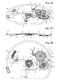
- FIGS 7A and 7B illustrate views respectively in perspective and from above of the alarm device according to the same preferred embodiment of the invention as in the preceding figures, with the illustration of the control device based on a column wheel 22, this time determining the mode C of time adjustment, that is to say the same mode as Figures 5A-C wherein the flip-flop 251 is oriented such that the second flip wheel 2512 meshes with the second wheel of the setting wheel of the second trigger wheel 72.
- a first major difference between Figures 5A, B and the Figures 7A, B relates to the addition of the column wheel 22, which controls the operating modes of the alarm device, as has already been explained in view of of the Figures 6A and 6B .
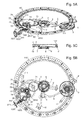
- FIGS. 8A and 8B illustrate respectively perspective and top views of the alarm device according to the same preferred embodiment of the invention as in the previous figures, with the illustration of the control device based on a column wheel 22, this time ci in one of the modes A or D in which the winding of the ringer barrel 93 is possible.
- FIGS. 8A and 8B also illustrate the entirety of the winding gear of the drum 93, which starts from the crown wheel 1031 and the coupling wheel 1032, which is precisely coupled here by a Breguet toothing to the first coupling gear 241 of the sliding pinion mounted on the rod 1033, and which allows to mesh the wheel 1032 in a determined direction of rotation, which is arranged to be that of the winding of the barrel 93, while generating no gearing in the opposite direction.
- the winding gear continues by a gear on the crown wheel 901, which itself meshes with a second winding wheel of the barrel 902 'coaxial and rotationally fixed with a first winding wheel of the barrel 902, meshing in a lower plane.
- the first winding wheel of the barrel 902 meshes with a third winding wheel of the barrel 903, coaxial and integral in rotation with a fourth winding wheel of the barrel 903 ', meshing in a lower plane with the fifth winding wheel of the barrel 904. , engaged with the ratchet wheel 93 "of the barrel, clearly visible on the Figure 8B .
- the ring gear 103 is actuated in a specific direction corresponding to that of the winding of the barrel 93, which is according to the preferred embodiment described chosen distinct from that of the base movement, so not to reduce the power reserve when actuating the alarm device.
- the energy supplied in the barrel 93 will be released during actuation of the alarm device, the ring gear being engaged with the outer toothing of the barrel 93 '.
- the ringing device, acting as an escapement is however not shown and only the anchor 91, integral with the hammer 9, is visible in the figures.
- the triggering means of the alarm device described (references 2,2 ', 3,3', 4,4 ', 5,6,6', 6 ', 7,7', 8.8 ', 10) are already explained in previous figures and will not be detailed for Figures 8A and 8C.
- the illustration of these tripping means next to the winding of the barrel 93 allows to appreciate their mutual positioning and the space generated on the plate.
- the coaxial arrangement of the first and second winding wheels 902, 902 'and the third and fourth wheels 903, 903' makes it possible precisely to reduce the space requirement in the plane of the plate.
- the Figures 9A, B are perspective views of the coupling gear between the timer of the basic movement and the hourly wheel 8, and the date correction wheel of the base movement of the dial and movement respectively.
- the Figures 9 C and D represent the same views as those of Figures A and B, respectively, but from above. These figures are intended to explain how the deadline wheel of date 2 is synchronized with the date date displayed in the window 107 of the watch face, visible on the figure 1 , and also how the deadline wheel 8 is also synchronized with the timer.
- the Figures 9A and B highlight the push rod 104, located at two o'clock on the figure 1 , and which allows the setting of the date displayed in the aperture 107.
- the setting consists of incrementing in steps of one unit each time the pusher 104 is pressed.
- Fixed pivoting at the bottom of the rod of the pusher 104 there is a lever for adjustment of the date of the base movement 1041, which acts on a date adjustment ratchet of the base movement 1042.
- This pawl 1042 drives the toothing of the third calendar program tooth wheel of the base movement 16, which is incremented by a tooth.
- the indexing elements 14 ', 15', and 16 ' have not been represented on the Figures 9A, B , CD , but they allow the unit indexing of each of the elements 14,15 and 16 which it ensures the indexed positioning.
- the rotation of the wheel 16 drives that of the wheel 11 and teeth 13, which increments the unit values 107 ", and respectively tens 107 'displayed in the aperture 107 via the wheel 15 and the star 14.
- the indexation of the date units each day by the basic movement is performed by means of the indexing cam 1043 ', integral with the 24-hour wheel, meshing with the first hour wheel of the base movement 1061, and which acts on the date adjustment ratchet of the base movement 1042.
- the indexing cam 1043 allows the incrementation of a unit of the third calendar program tooth wheel of the basic movement 16, and thus, as explained in the previous paragraph, the incrementation of the value of the units 107 "displayed in the aperture 107.
- the indexing cam 1043 ' is particularly clearly visible on the Figures 9B and 9D .
- the basic movement comprises two wheels of distinct hours located in different planes: a first hour wheel 1061, and a second hour wheel 1061 ', much larger, engaged with the timer.
- the first hour wheel 1061 meshes with the 24 hour wheel 1043, which itself meshes with the transmission wheel 1062, in mesh with the hourly timing wheel 8.
- the transmission wheel 1062 thus acts as a reference and ensures the permanent synchronization of the hourly wheel 8 with the 24-hour wheel 1043, even when the hands 106 and 106 "are set for the hours and minutes of the basic movement through the ring 105.
- the method for controlling and setting the alarm module described according to the invention makes it possible, thanks to the activation of the modes (A, B, C, D) with the aid of the push-button 102, and the setting of the parameters with the aid of the crown 103, a particularly effective handling of the clock watch, similar to that known for electromechanical watches which may include unique dedicated control and adjustment members.
- the solution therefore proposes an emulation of such an environment on a totally mechanical watch.
- the crown also allows an incremental and decremental adjustment of the time parameters used for the adjustment, here the date and the time, according to the direction of rotation. In this way, the use of such a mechanical member has the additional advantage of a faster adjustment because not limited to a single direction of adjustment to obtain the desired adjustment values.
Abstract
Description
La présente invention concerne un dispositif de commande et de réglage pour un mouvement horloger mécanique. L'invention est particulièrement adaptée notamment à des montres bracelets mécaniques de type montre réveil.The present invention relates to a control and adjustment device for a mechanical watch movement. The invention is particularly suitable in particular for mechanical wristwatches type watch alarm clock.
On connaît des dispositifs de réglage basés sur des couronnes et des tirettes, qui permettent de déterminer des fonctions différentes de la rotation de la couronne en fonction de la position de la tirette.Adjusting devices based on crowns and drawbars are known, which make it possible to determine different functions of the rotation of the crown as a function of the position of the pull tab.
On connaît également des dispositifs de commande pour chronographes utilisant des roues à colonnes, dans lesquelles la fonction de boutons poussoir peuvent déterminer différents modes de fonctionnement du chronographe.Also known are control devices for chronographs using column wheels, in which the push button function can determine different modes of operation of the chronograph.
L'inconvénient de ce type de mécanismes de commande et de réglage est qu'il n'est d'une part pas possible à l'utilisateur d'avoir conscience du mode de fonctionnement courant, d'une part, ce qui rend la navigation entre les modes relativement peu pratique et peut également donner lieu à des erreurs de manipulation.The disadvantage of this type of control mechanisms and adjustment is that it is not possible for the user to be aware of the current operating mode, on the one hand, which makes the navigation between the modes relatively impractical and can also give rise to handling errors.
On connaît par ailleurs, dans des montres électromécaniques, des montres avec lesquels différents modes sont sélectionnés à l'aide d'un premier organe de commande, souvent un poussoir, et le réglage de paramètres se fait à l'aide d'un ou plusieurs autres poussoirs. Ce genre de mécanisme présente l'avantage de proposer une navigation plus intuitive, mais n'est toutefois pas applicable à des mouvements ou modules mécaniques, pour lesquelles le réglage implique de nombreux organes de commande dédiés, disposés à des endroits différents sur la carrure de la montre. Cet encombrement empêche par ailleurs d'intégrer facilement des modules additionnels sur la platine, par manque de place.Furthermore, in electromechanical watches, there are known watches with which different modes are selected using a first control member, often a pusher, and the setting of parameters is done using one or more other pushers. This kind of mechanism has the advantage of proposing a more intuitive navigation, but is however not applicable to movements or mechanical modules, for which the adjustment involves many dedicated control members, arranged at different places on the middle of the watch. This size also prevents easily integrate additional modules on the plate, for lack of space.
Un but de la présente invention est de proposer un nouveau dispositif et une nouvelle méthode de commande pour un mouvement horloger exempts des limitations de l'art antérieur connu, qui permettent une utilisation plus commode et un encombrement plus restreint sur la platine.An object of the present invention is to provide a new device and a new control method for a watch movement free from the limitations of the known prior art, which allow a more convenient use and a smaller space on the platen.
Ces buts sont atteints notamment grâce à un mouvement horloger contenant un barillet, un organe de commande, un organe de réglage et des moyens d'affichage mécaniques, l'organe de commande permettant la sélection de modes de fonctionnement du mouvement horloger, les moyens d'affichage comprenant des premiers moyens d'affichage couplés à l'organe de commande pour l'affichage du mode de fonctionnement courant, caractérisé en ce que l'organe de réglage remplit au moins 3 fonctions distinctes selon le mode de fonctionnement choisi.These aims are achieved in particular by means of a clockwork movement containing a barrel, a control member, an adjustment member and mechanical display means, the control member enabling the selection of operating modes of the watch movement, the means of display comprising first display means coupled to the controller for displaying the current operating mode, characterized in that the control member performs at least 3 distinct functions according to the selected operating mode.
Ces buts sont également atteints par une méthode de commande pour mouvement horloger contenant un barillet, un organe de commande, un organe de réglage et des moyens d'affichage mécaniques, l'organe de commande permettant la sélection de modes de fonctionnement du mouvement horloger, les moyens d'affichage comprenant des premiers moyens d'affichage couplés à l'organe de commande pour l'affichage du mode de fonctionnement courant comprenant les étapes suivantes:
- une première étape de sélection d'un premier mode de fonctionnement pour le réglage dudit premier mode de réglage à l'aide dudit organe de commande;
- une première étape de réglage d'un premier paramètre temporel à l'aide dudit organe de réglage;
- une deuxième étape de sélection d'un deuxième mode de fonctionnement à l'aide dudit organe de commande;
- une deuxième étape de réglage d'un deuxième paramètre temporel distinct dudit premier paramètre temporel à l'aide dudit organe de réglage;
- une troisième étape de sélection d'un troisième mode de fonctionnement l'aide dudit organe de commande;
- une troisième étape de remontage d'un barillet dudit mouvement horloger à l'aide dudit organe de réglage.
- a first step of selecting a first operating mode for setting said first adjustment mode with said control member;
- a first step of setting a first time parameter using said adjustment member;
- a second step of selecting a second operating mode using said control member;
- a second step of setting a second temporal parameter distinct from said first temporal parameter with said adjustment member;
- a third step of selecting a third mode of operation using said control member;
- a third step of winding a cylinder of said watch movement using said adjustment member.
Un avantage de la solution proposée est de coupler les organes de réglage et de commande, de telle sorte qu'un organe de réglage unique puisse remplir plusieurs fonctions, ce qui libère de la place sur la platine pour d'autres modules horlogers.An advantage of the proposed solution is to couple the adjustment and control members, so that a single adjustment member can perform several functions, which frees room on the plate for other watch modules.
Par ailleurs, l'affichage instantané du mode courant permet de déterminer la fonction remplie par l'organe de réglage. La solution proposée permet ainsi un réglage simple et rapide, dispensant de l'usage de toute pièce électronique et tout en restant particulièrement convivial grâce la visualisation instantanée des modes de fonctionnement lors des étapes de réglage.Furthermore, the instantaneous display of the current mode makes it possible to determine the function performed by the adjustment member. The proposed solution thus allows a simple and fast adjustment, dispensing the use of any electronic part and while remaining particularly user-friendly thanks to the instantaneous visualization of the operating modes during the adjustment steps.
Un avantage additionnel de la solution proposée est d'avoir des organes de réglage et de commande dédiés, de telle sorte que l'utilisation est beaucoup plus intuitive. L'organe de réglage n'ayant par ailleurs qu'une seule position axiale quel que soit le mode de fonctionnement choisi, son usage s'en trouve facilité par rapport aux mécanismes à tirette traditionnels, pour lesquels le changement de mode nécessite une manipulation fastidieuse de la couronne.An additional advantage of the proposed solution is to have dedicated adjustment and control members, so that the use is much more intuitive. Moreover, since the adjusting member has only one axial position, whatever the mode of operation chosen, its use is facilitated over traditional pull mechanisms, for which changing the mode requires tedious operation. of the crown.
Des exemples de mise en oeuvre de l'invention sont indiqués dans la description et illustrée par les figures annexées dans lesquelles:
- La
figure 1 illustre une montre comprenant un dispositif de commande et de réglage selon une variante préférentielle de l'invention; - Les
figures 2 A,B,C illustrent des vues respectivement en perspective, en coupe et de dessus du mécanisme de déclenchement d'un dispositif d'alarme selon une variante préférentielle de l'invention, en position armée; - Les
figures 3 A,B,C illustrent des vues en perspective, en coupe et de dessus du mécanisme de déclenchement d'un dispositif d'alarme selon une variante préférentielle de l'invention, en position déclenchée; - Les
figures 4 A,B,C illustrent des vues en perspective, en coupe et de dessus d'un dispositif d'alarme selon une variante préférentielle de l'invention et plus particulièrement le rouage de réglage du jour de déclenchement de l'alarme; - Les f
igures 5 A,B,C illustrent des vues en perspective, en coupe et de dessus d'un dispositif d'alarme selon une variante préférentielle de l'invention, et plus particulièrement le rouage de réglage de l'horaire de déclenchement de l'alarme; - Les
figure 6 A et B illustrent respectivement des vues détaillées desfigures 4A et B , montrant plus précisément le mécanisme de commande pour la sélection et l'affichage des modes de fonctionnement, ainsi que l'aiguillage sur le rouage de réglage du jour de déclenchement; - Les
figures 7 A et B illustrent respectivement des vues détaillées desfigures 5 A et B , montrant plus précisément le mécanisme de commande pour la sélection et l'affichage des modes de fonctionnement, ainsi que l'aiguillage sur le rouage de réglage de l'horaire de déclenchement de l'alarme; - Les
figures 8 A et B illustrent des vues en perspective et de dessus du rouage de remontage du barillet de sonnerie utilisé selon une variante préférentielle de l'invention; - Les
figures 9 A,B ,C,D illustrent respectivement des vues côté cadran et côté mouvement, en perspective et de dessus, du rouage pour la correction du quantième du mouvement de base et le couplage du mouvement de base au dispositif d'alarme selon une variante préférentielle de l'invention.
- The
figure 1 illustrates a watch comprising a control and adjustment device according to a preferred embodiment of the invention; - The
Figures 2A, B, C illustrate respectively perspective views, in section and from above of the trigger mechanism of an alarm device according to a preferred embodiment of the invention, in the armed position; - The
Figures 3A, B, C illustrate perspective views, in section and from above of the triggering mechanism of an alarm device according to a preferred variant of the invention, in the tripped position; - The
Figures 4A, B, C illustrate views in perspective, in section and from above of an alarm device according to a preferred variant of the invention and more particularly the setting wheel of the alarm triggering day; - The F
igures 5 A, B, C illustrate views in perspective, in section and from above of an alarm device according to a preferred variant of the invention, and more particularly the work train for setting the alarm initiation time; - The
figure 6 A and B illustrate respectively detailed views ofFigures 4A and B , more specifically showing the control mechanism for the selection and display of the operating modes, as well as the switching on the setting wheel of the trip day; - The
Figures 7 A and B illustrate respectively detailed views ofFigures 5 A and B , showing more precisely the control mechanism for the selection and display of the operating modes, as well as the switching on the work train for setting the alarm trigger time; - The
Figures 8 A and B illustrate views in perspective and from above of the winding train of the striking barrel used according to a preferred variant of the invention; - The
Figures 9A, B ,CD respectively illustrate views of the dial side and movement side, in perspective and from above, of the gear train for the correction of the calendar of the base movement and the coupling of the basic movement to the alarm device according to a preferred variant of the invention.
La
Le module d'alarme décrit ci-après permet, selon ce mode de réalisation préférentiel, l'actionnement d'un dispositif de sonnerie, mais il pourrait également actionner une alarme vibrante, c'est à dire ne générant pas nécessairement intrinsèquement un son. On comprendra également que le réglage de deux paramètres temporels distincts avec le même organe de réglage 103 pourrait s'appliquer à d'autres types de paramètres.The alarm module described below allows, according to this preferred embodiment, the actuation of a ringing device, but it could also actuate a vibrating alarm, that is not necessarily generating intrinsically a sound. It will also be understood that the setting of two distinct time parameters with the
Sur le cadran de la montre, on peut distinguer, partant du centre, les aiguilles du mouvement de la montre, à savoir l'aiguille des heures 106, celle des minutes 106' et celle des secondes 106". A trois heures se trouve un guichet 107, au travers duquel on peut visualiser le quantième, formé par un affichage dissocié des dizaines 107' et des unités 107", les dizaines et les unités se trouvant sur des disques distincts ayant leurs propres moyens d'entraînement, la croix 14 et la roue 15 illustrée sur les figures suivantes, et notamment les
A neuf heures sur le cadran se trouve une échelle annulaire contenant des inscriptions correspondant à des valeurs de quantième 109". Une aiguille 109 pointe sur une valeur de quantième choisie pour le déclenchement 109', qui déterminera le jour d'actionnement du dispositif d'alarme. Sur la face interne de l'anneau que forme l'échelle annulaire 109" se trouve un guichet 108, qui permet d'afficher le mode de fonctionnement de la montre réveil. Sur la
La carrure de la montre réveil 101 porte deux boutons poussoirs 102 et 104. Le poussoir 104 permet de corriger les valeurs de quantième, par incrémentations unitaires lors de chaque pression sur le poussoir 104. La correction du quantième, ainsi que le couplage du mouvement de base qui permet l'affichage de l'heure courante par les aiguilles 106, 106' et 106", sont expliquées en détail à l'aides des
Lors de chaque pression sur le poussoir 102, chaque changement de mode a aussi une influence sur la fonction de la couronne de réglage 103, qui permet alternativement de remonter un barillet de sonnerie 93, illustré plus loin notamment sur les
L'avantage d'utiliser une telle couronne 103 comme organe de réglage permet d'effectuer le réglage des paramètres temporels choisis dans n'importe quel sens, c'est-à-dire incrémental ou décrémental. La position différenciée des différentes valeurs de déclenchement de l'alarme pour le quantième 109' et l'horaire 110' permettent par ailleurs un réglage séquentiel intuitif dans lequel on peut instantanément visualiser la valeur réglée. L'affichage simultané des modes de fonctionnement, dont les deux modes de réglage B et C, contribuent à rendre le réglage et la visualisation des paramètres temporels à régler des plus commodes. Par ailleurs, la disposition de l'affichage de la valeur de quantième de déclenchement 109' en regard du quantième du mouvement de base formé par les indications de dizaine 107', et d'unités 107", les indications étant disposées respectivement à 9 heures et 3 heures sur le cadran, permettent une comparaison très rapide de ces valeurs de quantième et donc une lecture aisée; le choix d'un mode d'affichage différent par aiguille 109 pour le déclenchement de l'alarme et par affichage numérique pour le quantième courant permet par ailleurs d'éviter toute confusion sur l'interprétation des valeurs de quantième affichées. La valeur numérique donnera sans effort l'indication souhaitée du quantième courant, qui est celle consultée a priori le plus souvent par l'utilisateur sur laquelle il se focalisera a priori en premier spontanément.The advantage of using such a
La montre réveil de la
Les
Sur les
Les moyens de déclenchement du dispositif d'alarme décrit ( références 2,2',3,3',4,4',5,6,6',6',7,7',8,8',10 sur les
Comme on peut le constater sur toutes les
La
Les
Ce mécanisme en cascade permet d'envisager, bien que cette variante ne soit pas décrite en détail ni illustrée, de rajouter un étage supplémentaire de déclenchement pour une échéance mensuelle, ou encore une échéance d'année, par couplage d'une troisième roue de déclenchement à une roue d'échéance des mois, voire même d'une quatrième une roue de déclenchement à une roue d'échéance d'année (roue unitaire de 0 à 9), ou encore d'autres paramètres temporels.This cascade mechanism makes it possible to envisage, although this variant is not described in detail or illustrated, to add an additional trigger stage for a monthly deadline, or a year-end, by coupling a third wheel of triggering a wheel of maturity of the months, or even a fourth a tripping wheel to a year-end wheel (unit wheel from 0 to 9), or other temporal parameters.
La commande du dispositif d'alarme selon le mode de réalisation préférentiel illustré peut comprendre une étape de désactivation D1 du dispositif d'alarme, correspondant à l'activation d'un mode de désactivation spécifique D par pression sur le bouton poussoir 102. Cette étape de désactivation D1, peut être effectuée à tout moment, indépendamment du déclenchement effectif du dispositif d'alarme, les fréquences d'oscillation du marteau 9 et l'agencement des éléments de préhension 6" de l'élément déclencheur de quantième 6 et du marteau 9' permettant l'arrêt instantané de la sonnerie en cas d'activation du mode D même en cas de fonctionnement de la sonnerie. L'étape de désactivation D1 correspond, selon l'ordre défilement des modes de la montre réveil 101, à une pression sur le bouton poussoir 102 alors que le mode de fonctionnement courant est le mode A d'enclenchement de l'alarme, représenté par l'icône de sonnerie dans le guichet 108. Le mode de désactivation D correspond à l'affichage d'un icône de sonnerie barré dans le guichet 108, comme sur la
Pour la description des figures suivantes, 4 A,B,C, 5 A,B,C, 6 A,B, 7 A,B et 8 A,B, les moyens de déclenchement, en tous points identiques à ceux décrits dans les
Les
Le rouage de réglage du quantième de déclenchement 109' comprend une première roue 31 munie d'un pignon 31', qui engrène avec une deuxième roue intermédiaire 32 de renvoi engrenant sur la troisième roue 33 entraînant l'aiguille 109 d'affichage du quantième de déclenchement, située sur un plan supérieur. La rotation de la troisième roue 33 est indexée par unité de quantième grâce à l'élément d'indexation élastique 33'. Le nombre des dents des roues 33, 32, 31', 31 et 3 est choisi de telle sorte que l'angle de rotation de la troisième roue 33 soit exactement transmis à la première roue de déclenchement 3 afin que ces dernières fonctionnent de manière totalement synchronisée. Pour ce faire, il est par exemple possible de choisir un nombre de dents égal pour les roues 33 et le pignon 31', ainsi que pour les roues 31 et 3. Les roues 33 et le pignon 31' auront ainsi la même vitesse angulaire de même que les roues 31 et 3; puisque la première roue 31 et le pignon 31' on également la même, par transitivité celle de la roue 3 sera égale à celle de la troisième roue 33. Le rouage se prolonge ensuite par les quatrième et cinquième roues 34 et 35, la quatrième roue 34 engrenant sur la troisième roue 33 et la cinquième roue 35 engrenant sur la roue 34. La cinquième roue 35 engrène ensuite sur une roue de bascule 2522, la deuxième en partant de la couronne 103, qui engrène elle-même sur une première roue de bascule 2511 située sur la même bascule 251, qui est orientée différemment selon les modes de fonctionnement, et plus précisément entre les modes de fonctionnement B et C qui sont des modes de réglage. Dans le cas du mode de fonctionnement B du réglage de la valeur de quantième 109' de déclenchement, illustré par les
Les
La
La
La
Les
Comme on peut le constater sur la
- 222 : 0 = position du levier 24 permettant le remontage du barillet de sonnerie 93, engrenage des éléments 1032-241 ; 1 = position du levier permettant le réglage des paramètres de temps, engrenage des éléments 242-26;
- 223 : 0 = position de la bascule pour un engrenage sur le rouage du réglage du quantième, engrenage des éléments 2512-35 ; 1 = position de la bascule pour un engrenage sur le rouage de réglage de l'horaire, engrenage des éléments 2512-72 ;
- 224 : 0 = bras en position armée, bloquante ; 1 = bras en position dégagée (mode A du dispositif d'alarme).
- 222: 0 = position of the
lever 24 for reassembly of theringer barrel 93, gear elements 1032-241; 1 = position of the lever allowing adjustment of the time parameters, gearing elements 242-26; - 223: 0 = position of the scale for a gear on the gear wheel of the date adjustment, gear of elements 2512-35; 1 = rocker position for a gear on the time control gear, gear elements 2512-72;
- 224: 0 = arm in armed position, blocking; 1 = arm in open position (mode A of the alarm device).
L'état global de la roue à colonne 22 peut ainsi être résumé par le tableau suivant, dans lequel le changement d'état de chaque étage correspond à un déplacement angulaire d'une dent de l'étage inférieur 221. Selon le mode de réalisation préférentiel illustré, la roue de l'étage inférieur comprend 12 dents et donc 12 états sont représentés; l'homme du métier comprendra toutefois, étant donné la périodicité constatée, qu'un nombre de dents égal à n'importe quel multiple de la période pourra être choisi.
- 222 : 0110 0110 0110
- 223 : 1100 1100 1100
- 224 : 0001 0001 0001
- 222: 0110 0110 0110
- 223: 1100 1100 1100
- 224: 0001 0001 0001
En lisant colonne par colonne on remarque bien effectivement que les différents états du système (010, 110, 100, 001) sont répétés après incrémentation de 4 dents de la roue de l'étage inférieur 221; chacun des 4 états correspond donc aux différents modes du système (010 = mode D de désactivation 110 = mode B de réglage de quantième, le premier « 1 » indiquant que le système est en mode réglage et le 2e « 1 » indiquant le type de réglage effectué, 100 = mode C de réglage horaire, et enfin 001 = mode A d'enclenchement dudit dispositif d'alarme.) Les positions d'activation ou de désactivation sur les cames des étages 222 et 223 illustrent comment la fonction exercée par la couronne 103 est déterminée (0 = remontage, 1= réglage, avec 11 = 1er type de réglage et 10 = 2e type de réglage).Reading column by column it is indeed noted that the various states of the system (010, 110, 100, 001) are repeated after incrementation of 4 teeth of the wheel of the
L'homme du métier comprendra que des contraintes fonctionnelles peuvent être appliquées au système comme par exemple: lorsque la valeur de l'étage 222 est à 1, la valeur de l'étage 224 est de préférence à 0, pour qu'aucun déclenchement de l'alarme ne puisse être indûment provoqué pendant le réglage, comme c'est le cas ici selon le mode de réalisation préférentiel illustré, qui décrit une méthode de commande dans laquelle les modes de réglage B,C et d'activation A sont dissociés. D'autres contraintes sont envisageables avec la roue à colonnes 22 décrite, qui permet un nombre de modes potentiels égal à 8 (2 états possibles à chaque étage sur lesquels sont agencés des cames, soit 222,223,224, à la puissance du nombre de ces étages, égal à 3).Those skilled in the art will understand that functional constraints can be applied to the system, for example: when the value of
L'avantage de l'utilisation d'une telle roue à colonne 22 permet de gérer les états du système à partir d'un organe de commande centralisé, dont la disposition peut être déterminée sur la platine. Le fait que cet organe de commande soit actionné par un bouton poussoir 102 unique permet le défilement des modes de manière intuitive, chaque pression correspondant à une étape de changement de mode. Cet agencement dispense de l'usage d'organes de réglage dédiés à des fonctions déterminées; selon le mode de réalisation préférentiel de l'invention, la couronne 103 remplit 3 fonctions différentes. L'homme du métier comprendra que l'aiguillage sur différents rouages de réglage peut être appliqué à d'autres paramètres temporels indépendants, et pas seulement des valeurs de quantième 109' et une valeur horaire 110" combinant des heures et des minutes.The advantage of the use of such a
Les
Les
Comme déjà indiqué précédemment dans la description, les moyens de déclenchement du dispositif d'alarme décrit ( références 2,2',3,3',4,4',5,6,6',6',7,7',8,8',10 ) sont déjà expliquées dans des figures précédentes et ne seront donc pas détaillées pour les
On peut visualiser, sur la
- la cloche barrée: mode D, correspondant au mode désactivé. Ce mode peut être activé indépendamment de l'actionnement effectif de la sonnerie, comme expliqué précédemment.
- le « d » pour « day »: mode B, correspondant au réglage du quantième de déclenchement 109'. C'est le mode qui suit le mode D après une pression sur le bouton poussoir 102, auquel est liée la tige 1021,
car le cliquet 21 entraîne alors la roue à colonnes 22 en rotation dans le sens anti-horaire, et donc la roue 23, auquel le disque d'affichage 23' est fixé, dans le sens horaire. Dans ce mode,la couronne 103 permet d'effectuer un réglage de la valeur de quantième de déclenchement 109'; le réglage est par ailleurs possible dans les deux sens, c'est à dire que la rotation de la couronne 103 dans un premier sens engendre la rotation de l'aiguille 109 dans un premier sens, pas à pas grâce à l'élément élastique d'indexation 33', et que la rotation de la couronne dans le sens inverse engendre la rotation de l'aiguille 109 dans le sens inverse. Cette fonctionnalité permet d'augmenter considérablement l'aisance du réglage. - le « h » pour « hour »: mode C, correspondant au réglage de l'horaire de déclenchement 110'. C'est le mode qui suit le mode B après une autre pression sur le bouton poussoir 102. Dans ce mode,
la couronne 103 permet d'effectuer un réglage d'une valeur d'horaire de déclenchement, avec, selon le mode de réalisation décrit, une précision au quart d'heure; le réglage est par ailleurs possible dans les deux sens, c'est à dire que la rotation de la couronne 103 dans un premier sens engendre la rotation de l'anneau portant les valeurs de déclenchement horaire 110" dans un premier sens, pas à pas grâce aux éléments d'indexation 111, et que la rotation de la couronne dans le sens inverse engendre la rotation de l'anneau dans le sens inverse. Cette fonctionnalité permet également d'augmenter considérablement l'aisance du réglage, dont la visualisation et facilitée par ailleurs grâce à l'affichage dissocié des paramètres de réglage, le guichet 110 et l'index 110"' montrant l'horaire de déclenchement étant situés à 6 heures, tandis que l'aiguille 109 pointant sur la valeur de quantième de déclenchement 109' est située à 9 heures. Le réglage séquentiel de chaque paramètre temporel avec le même organe de réglage, i.e. la couronne 103, est du reste particulièrement intuitif, comme sur une montre électronique.
- the barred bell: mode D, corresponding to the deactivated mode. This mode can be activated independently of the effective operation of the ringer, as explained above.
- the "d" for "day": mode B, corresponding to the setting of the
trigger date 109 '. This is the mode which follows the mode D after a pressure on thepush button 102, to which is connected therod 1021, because thepawl 21 then drives thecolumn wheel 22 in rotation in the counterclockwise direction, and therefore thewheel 23, to which the display disc 23 'is fixed, in the clockwise direction. In this mode, thering 103 makes it possible to adjust thetrigger date value 109 '; the adjustment is also possible in both directions, that is to say that the rotation of thering 103 in a first direction causes the rotation of theneedle 109 in a first direction, step by step through the elastic element of 33 'indexing, and that the rotation of the ring in the opposite direction causes the rotation of theneedle 109 in the opposite direction. This feature greatly increases the ease of adjustment. - the "h" for "hour": mode C, corresponding to the setting of the triggering time 110 '. This is the mode that follows the mode B after another press on the
pushbutton 102. In this mode, thecrown 103 makes it possible to adjust a trigger time value, with, according to the embodiment describes a quarter-hour precision; the adjustment is also possible in both directions, that is to say that the rotation of thering 103 in a first direction causes the rotation of the ring bearing the time-release values 110 "in a first direction, step by step thanks to theindexing elements 111, and that the rotation of the ring in the opposite direction causes the rotation of the ring in the opposite direction.This feature also makes it possible to considerably increase the ease of adjustment, including visualization and facilitated Moreover, the dissociated display of the adjustment parameters, thewindow 110 and theindex 110 "'showing the trigger time being located at 6 o'clock, while theneedle 109 pointing to thetrigger date value 109 is located at 9 o'clock. The sequential adjustment of each time parameter with the same adjustment member, ie thecrown 103, is moreover particularly intuitive, as on an electronic watch.
Toutefois, une fois ce deuxième réglage effectué, le dispositif d'alarme n'est toujours pas activé et il faut effectuer une étape supplémentaire distincte d'enclenchement A1 que l'alarme soit activée, car dans le mode C, le bras de dégagement est toujours situé sous le pont de dégagement 5, empêchement tout mouvement vertical de la roue de déclenchement horaire 7 et ainsi la libération du marteau de sonnerie 9. Selon un mode de réalisation alternatif, on pourrait imaginer que cette étape d'activation A1 ne soit pas nécessaire et que l'activation du mode de réglage du dernier paramètre à déterminer enclenche simultanément le dispositif de sonnerie; cette solution présente toutefois l'inconvénient de pouvoir indûment déclencher l'alarme lors du réglage, ce qui en rend l'usage plus délicat, dans la mesure où il faut s'assurer que l'étape de réglage de fasse jamais coïncider les paramètres temporels de déclenchement à l'heure courante. La solution préférentielle comprenant une étape distincte d'enclenchement A1 permet donc un meilleur confort de réglage.
- la cloche: correspondant au mode A d'enclenchement de l'alarme, activé par une pression sur le bouton poussoir 102 depuis le mode C précédent. Cette pression sur le bouton poussoir 102 est l'étape A1 d'enclenchement nécessaire à l'activation de l'alarme, qui libère le bras de dégagement du pont de dégagement 5. On pourra toutefois noter que, selon le mode de réalisation décrit même cette étape d'activation A1 n'est pas suffisante pour s'assurer que le dispositif d'alarme selon l'invention puisse générer une sonnerie ou tout autre type d'avertissement. Ceci ne pourra être réalisé que par un actionnement additionnel de la couronne 103 dans le sens de remontage du barillet 93; toutefois, cet actionnement aura pu être effectué au préalable et il n'est pas nécessaire, comme déjà expliqué précédemment, de se trouver dans le mode A pour pouvoir effectuer le remontage du barillet 93 de sonnerie, cette étape de remontage peut également être effectuée dans le mode D de désactivation. Dans un mode de réalisation alternatif selon lequel la sonnerie utilise le barillet du mouvement de base, une telle opération de remontage ne serait toutefois pas nécessaire mais simplement souhaitable pour ne pas entamer trop substantiellement la réserve de marche; dans ce cas la seule condition pour que le dispositif d'alarme puisse fonctionner serait que le mouvement horloger de base soit lui-même en fonction lors de l'enclenchement de l'alarme.
- the bell: corresponding to the mode of activation of the alarm, activated by pressing the
pushbutton 102 from the previous mode C. This pressure on thepush button 102 is the activation step A1 needed to the activation of the alarm, which releases the release arm of therelease bridge 5. It may however be noted that, according to the embodiment described even this activation step A1 is not sufficient to ensure that the alarm device according to the invention can generate a ringing or any other type of warning. This can only be achieved by an additional actuation of thering gear 103 in the winding direction of thebarrel 93; however, this actuation could have been done beforehand and it is not necessary, as already explained above, to be in mode A to be able to perform the winding of thebarrel 93 ringer, this reassembly step can also be performed in D mode of deactivation. In an alternative embodiment in which the buzzer uses the barrel of the base movement, such a winding operation would not be necessary, but simply desirable not to too substantially reduce the power reserve; in this case the only condition for the alarm device to function is that the basic watch movement is itself in operation when the alarm is switched on.
Le fait que l'activation de tous les modes de réglage A,B,C,D soit simultanément visualisé par l'intermédiaire de l'icône correspondant sur le disque 23' dans le guichet 108 permet également d'améliorer la commodité d'usage; les réglages sont effectués de manière séquentielle, à chaque fois avec la couronne 103 après activation d'un mode déterminant sa fonction et les conséquences de sa rotation par pression sur le bouton poussoir 102. L'enclenchement de l'alarme nécessite ainsi, selon le mode de réalisation préférentiel décrit, trois pressions successives du bouton poussoir 102, ainsi que l'actionnement d'au moins 3 fois la couronne de réglage 103, respectivement pour le remontage du barillet, avant ou après les étapes de réglage, et les deux étapes de réglage de deux paramètres temporels distincts, ici une valeur de quantième de déclenchement 109' et une valeur d'horaire de déclenchement 110'.The fact that the activation of all adjustment modes A, B, C, D is simultaneously displayed via the corresponding icon on the disk 23 'in the
Les
Les
La synchronisation de la roue d'échéance de quantième 2 avec le quantième du mouvement de base est simplement assurée par l'engrenage mutuel de la deuxième roue dentée du programme de quantième du mouvement de base 12 avec la roue d'échéance de quantième 2, comme cela est particulièrement visible sur la
Le mouvement de base comprend deux roues des heures distinctes situées dans des plans différents: une première roue des heures 1061, et une deuxième roue des heures 1061', beaucoup plus grande, en prise avec la minuterie. La première roue des heures 1061 engrène sur la roue de 24 heures 1043, qui elle-même engrène sur la roue de transmission 1062, en prise avec la roue d'échéance horaire 8. La roue de transmission 1062 fait ainsi office de renvoi et assure la synchronisation permanente de la roue d'échéance horaire 8 avec la roue de 24 heures 1043, même en cas de réglage des aiguilles 106 et 106" des heures et des minutes du mouvement de base par l'intermédiaire de la couronne 105.The basic movement comprises two wheels of distinct hours located in different planes: a
La méthode pour la commande et le réglage du module d'alarme décrit selon l'invention permet, grâce à l'activation des modes (A,B,C,D) à l'aide du bouton poussoir 102, et le réglage des paramètres temporels à l'aide de la couronne 103, une manipulation particulièrement efficace de la montre réveil, similaire à celle connue pour les montres électromécaniques qui peuvent comprendre des organes de commande et de réglage dédiés uniques. La solution propose donc une émulation d'un tel environnement sur une montre totalement mécanique. Toutefois, la couronne permet en outre un réglage incrémental et décrémental des paramètres temporels utilisés pour le réglage, ici le quantième et l'horaire, selon le sens de rotation. De cette façon, l'usage d'un tel organe mécanique présente l'avantage additionnel d'un réglage plus rapide car non limité à un seul sens de réglage pour obtenir les valeurs de réglage souhaitées.The method for controlling and setting the alarm module described according to the invention makes it possible, thanks to the activation of the modes (A, B, C, D) with the aid of the push-
Bien que l'invention ait été décrite en relation avec un module d'alarme couplé au mouvement de base, on comprendra que les dispositifs et méthode de commande décrits utilisant la combinaison d'un poussoir 102, d'une couronne 103 et d'une roue à colonnes 22 permet de déterminer plus de modes de fonctionnement que les 4 modes A,B,C,D décrits et pourrait être utilisée pour activer et respectivement désactiver tout type de rouage alimenté par un barillet, et effectuer différents type de réglages sur ce rouage. On pourrait également envisager le poussoir et la couronne par d'autres type d'organes de commande et de réglage, pour autant que la commodité d'usage ne s'en trouve pas détériorée; la couronne et le poussoir pourraient par exemple être remplacés par des molettes disposées sur la carrure de la montre.Although the invention has been described in connection with an alarm module coupled to the basic movement, it will be understood that the described control devices and method using the combination of a
Claims (14)
Priority Applications (5)
| Application Number | Priority Date | Filing Date | Title |
|---|---|---|---|
| EP10156806.1A EP2367080B1 (en) | 2010-03-17 | 2010-03-17 | Device for controlling and adjusting a timepiece movement |
| CN2013100042599A CN103064279A (en) | 2010-03-17 | 2011-03-17 | Device for controlling and adjusting a timepiece movement |
| JP2011059392A JP5519563B2 (en) | 2010-03-17 | 2011-03-17 | Control and setting device for clock movement |
| CN201110064480.4A CN102193484B (en) | 2010-03-17 | 2011-03-17 | Device for controlling and adjusting a timepiece movement |
| HK12102712.9A HK1162210A1 (en) | 2010-03-17 | 2012-03-19 | Control & setting device for a timepiece movement |
Applications Claiming Priority (1)
| Application Number | Priority Date | Filing Date | Title |
|---|---|---|---|
| EP10156806.1A EP2367080B1 (en) | 2010-03-17 | 2010-03-17 | Device for controlling and adjusting a timepiece movement |
Publications (2)
| Publication Number | Publication Date |
|---|---|
| EP2367080A1 true EP2367080A1 (en) | 2011-09-21 |
| EP2367080B1 EP2367080B1 (en) | 2019-01-16 |
Family
ID=42676816
Family Applications (1)
| Application Number | Title | Priority Date | Filing Date |
|---|---|---|---|
| EP10156806.1A Active EP2367080B1 (en) | 2010-03-17 | 2010-03-17 | Device for controlling and adjusting a timepiece movement |
Country Status (4)
| Country | Link |
|---|---|
| EP (1) | EP2367080B1 (en) |
| JP (1) | JP5519563B2 (en) |
| CN (2) | CN102193484B (en) |
| HK (1) | HK1162210A1 (en) |
Cited By (4)
| Publication number | Priority date | Publication date | Assignee | Title |
|---|---|---|---|---|
| EP3361323A1 (en) * | 2017-02-13 | 2018-08-15 | Rolex Sa | Winding system of a timepiece |
| EP4216000A1 (en) * | 2022-01-24 | 2023-07-26 | Bulgari Horlogerie S.A. | Control device for a timepiece |
| CH719375A1 (en) * | 2022-01-24 | 2023-07-31 | Bulgari Horlogerie Sa | Control device for a timepiece. |
| EP4270114A1 (en) * | 2022-04-25 | 2023-11-01 | Montres Breguet S.A. | Device for selecting and controlling functions of a timepiece movement |
Families Citing this family (6)
| Publication number | Priority date | Publication date | Assignee | Title |
|---|---|---|---|---|
| CN102778838B (en) * | 2011-10-27 | 2014-07-02 | 王维加 | Large clock |
| CH709675A2 (en) * | 2014-05-21 | 2015-11-30 | Blancpain Sa | Mechanism sound display with song selection for a timepiece to ring. |
| EP3070535B1 (en) * | 2015-03-18 | 2020-04-29 | Glashütter Uhrenbetrieb GmbH | Barrel with largely constant torque |
| TWI566060B (en) * | 2015-04-24 | 2017-01-11 | 宏碁股份有限公司 | Wearable electronic device |
| EP3422119B1 (en) * | 2017-05-29 | 2021-06-30 | The Swatch Group Research and Development Ltd | Universal device for preparing a watch |
| EP3719589A1 (en) | 2018-05-21 | 2020-10-07 | The Swatch Group Research and Development Ltd | Universal device for winding and time-setting of a watch |
Citations (5)
| Publication number | Priority date | Publication date | Assignee | Title |
|---|---|---|---|---|
| FR1106848A (en) * | 1954-08-18 | 1955-12-23 | Device for transforming an ordinary watch into an alarm clock | |
| DE3137399A1 (en) * | 1981-09-19 | 1983-04-14 | Pforzheimer Uhren-Rohwerke Porta Gmbh & Co, 7530 Pforzheim | Control device for setting the alarm time in small clocks/watches |
| EP1394637A1 (en) * | 2002-08-27 | 2004-03-03 | Frédéric Piguet S.A. | Timepiece, in particular wristwatch, comprising an alarm mechanism |
| EP1939699A1 (en) * | 2006-12-29 | 2008-07-02 | Montres Breguet S.A. | Multifunctional coaxial corrector device |
| EP2012199A2 (en) * | 2007-07-02 | 2009-01-07 | Rolex Sa | Timepiece fitted with a device for the control of functions and/or time indications |
Family Cites Families (6)
| Publication number | Priority date | Publication date | Assignee | Title |
|---|---|---|---|---|
| JPS5980776U (en) * | 1982-11-24 | 1984-05-31 | 株式会社精工舎 | alarm clock |
| WO1995013570A1 (en) * | 1993-11-10 | 1995-05-18 | Citizen Watch Co., Ltd. | Alarm clock |
| JP3742160B2 (en) * | 1996-11-15 | 2006-02-01 | シチズン時計株式会社 | Electronic watch with water depth gauge |
| JP3629895B2 (en) * | 1997-06-16 | 2005-03-16 | セイコーエプソン株式会社 | Electronically controlled mechanical clock |
| WO2002077724A2 (en) * | 2001-03-21 | 2002-10-03 | Glashütter Uhrenbetrieb GmbH | Timepiece comprising a striking device |
| US20050249051A1 (en) * | 2004-03-24 | 2005-11-10 | Philippe Cogoli | Timepiece |
-
2010
- 2010-03-17 EP EP10156806.1A patent/EP2367080B1/en active Active
-
2011
- 2011-03-17 CN CN201110064480.4A patent/CN102193484B/en active Active
- 2011-03-17 CN CN2013100042599A patent/CN103064279A/en active Pending
- 2011-03-17 JP JP2011059392A patent/JP5519563B2/en active Active
-
2012
- 2012-03-19 HK HK12102712.9A patent/HK1162210A1/en unknown
Patent Citations (5)
| Publication number | Priority date | Publication date | Assignee | Title |
|---|---|---|---|---|
| FR1106848A (en) * | 1954-08-18 | 1955-12-23 | Device for transforming an ordinary watch into an alarm clock | |
| DE3137399A1 (en) * | 1981-09-19 | 1983-04-14 | Pforzheimer Uhren-Rohwerke Porta Gmbh & Co, 7530 Pforzheim | Control device for setting the alarm time in small clocks/watches |
| EP1394637A1 (en) * | 2002-08-27 | 2004-03-03 | Frédéric Piguet S.A. | Timepiece, in particular wristwatch, comprising an alarm mechanism |
| EP1939699A1 (en) * | 2006-12-29 | 2008-07-02 | Montres Breguet S.A. | Multifunctional coaxial corrector device |
| EP2012199A2 (en) * | 2007-07-02 | 2009-01-07 | Rolex Sa | Timepiece fitted with a device for the control of functions and/or time indications |
Cited By (7)
| Publication number | Priority date | Publication date | Assignee | Title |
|---|---|---|---|---|
| EP3361323A1 (en) * | 2017-02-13 | 2018-08-15 | Rolex Sa | Winding system of a timepiece |
| CN108427259A (en) * | 2017-02-13 | 2018-08-21 | 劳力士有限公司 | System for winding up to timer |
| US11112757B2 (en) | 2017-02-13 | 2021-09-07 | Rolex Sa | System for winding a timepiece |
| CN108427259B (en) * | 2017-02-13 | 2022-06-24 | 劳力士有限公司 | System for winding a timepiece |
| EP4216000A1 (en) * | 2022-01-24 | 2023-07-26 | Bulgari Horlogerie S.A. | Control device for a timepiece |
| CH719375A1 (en) * | 2022-01-24 | 2023-07-31 | Bulgari Horlogerie Sa | Control device for a timepiece. |
| EP4270114A1 (en) * | 2022-04-25 | 2023-11-01 | Montres Breguet S.A. | Device for selecting and controlling functions of a timepiece movement |
Also Published As
| Publication number | Publication date |
|---|---|
| CN102193484A (en) | 2011-09-21 |
| CN102193484B (en) | 2014-04-16 |
| EP2367080B1 (en) | 2019-01-16 |
| HK1162210A1 (en) | 2012-08-24 |
| CN103064279A (en) | 2013-04-24 |
| JP5519563B2 (en) | 2014-06-11 |
| JP2011197004A (en) | 2011-10-06 |
Similar Documents
| Publication | Publication Date | Title |
|---|---|---|
| EP2367080B1 (en) | Device for controlling and adjusting a timepiece movement | |
| EP2339413B1 (en) | Timepiece movement equipped with a vibrating alarm | |
| EP3021175B1 (en) | Split-seconds device with epicycloidal train for a timepiece | |
| EP2362277A1 (en) | On-demand time zone displayed on the main hand of a timepiece | |
| CH704948B1 (en) | Watch electromechanical chronograph retrograde. | |
| EP3502801B1 (en) | Chronograph repetition mechanism with safety | |
| EP2367076B1 (en) | Alarm device suitable for being set 30 days in advance | |
| EP3945374A1 (en) | Sympathique timepiece assembly | |
| CH702846A2 (en) | Mechanical clock movement for use in mechanical alarm wristwatch, has display disk coupled with control unit for displaying current operating mode of movement, and adjusting unit satisfying three different functions based on chosen mode | |
| CH702844A2 (en) | Alarm device for alarm watch, has adjusting component acting on triggering units that are associated to predetermined date triggering value, where units include triggering wheels flatten on date and time expiry wheels, respectively | |
| EP4189494A1 (en) | Sympathetic timekeeping assembly | |
| EP3862818A1 (en) | Watch comprising a winding mechanism | |
| EP4189491A1 (en) | Sympathetic timekeeping assembly | |
| EP4189490A1 (en) | Sympathetic timekeeping assembly | |
| CH717650A2 (en) | Step-by-step time-setting process for a sympathetic watch. | |
| CH717655A2 (en) | Method for setting the permanent time of a sympathetic watch. | |
| CH717654A2 (en) | Process for setting the time of a sympathetic watch. | |
| CH717696A2 (en) | Nice set of clocks. | |
| CH717699B1 (en) | Nice set of clocks. | |
| CH717651A2 (en) | Method of winding a sympathetic watch. | |
| EP4189493A1 (en) | Sympathetic timekeeping assembly | |
| CH717695A2 (en) | Nice set of clocks. | |
| CH717653A2 (en) | Nice set of clocks. | |
| WO2022022827A1 (en) | Sympathetic timekeeping assembly | |
| CH717701A1 (en) | Nice set of clocks. |
Legal Events
| Date | Code | Title | Description |
|---|---|---|---|
| PUAI | Public reference made under article 153(3) epc to a published international application that has entered the european phase |
Free format text: ORIGINAL CODE: 0009012 |
|
| AK | Designated contracting states |
Kind code of ref document: A1 Designated state(s): AT BE BG CH CY CZ DE DK EE ES FI FR GB GR HR HU IE IS IT LI LT LU LV MC MK MT NL NO PL PT RO SE SI SK SM TR |
|
| AX | Request for extension of the european patent |
Extension state: AL BA ME RS |
|
| 17P | Request for examination filed |
Effective date: 20120321 |
|
| STAA | Information on the status of an ep patent application or granted ep patent |
Free format text: STATUS: EXAMINATION IS IN PROGRESS |
|
| 17Q | First examination report despatched |
Effective date: 20180124 |
|
| GRAP | Despatch of communication of intention to grant a patent |
Free format text: ORIGINAL CODE: EPIDOSNIGR1 |
|
| STAA | Information on the status of an ep patent application or granted ep patent |
Free format text: STATUS: GRANT OF PATENT IS INTENDED |
|
| INTG | Intention to grant announced |
Effective date: 20180921 |
|
| GRAS | Grant fee paid |
Free format text: ORIGINAL CODE: EPIDOSNIGR3 |
|
| GRAA | (expected) grant |
Free format text: ORIGINAL CODE: 0009210 |
|
| STAA | Information on the status of an ep patent application or granted ep patent |
Free format text: STATUS: THE PATENT HAS BEEN GRANTED |
|
| AK | Designated contracting states |
Kind code of ref document: B1 Designated state(s): AT BE BG CH CY CZ DE DK EE ES FI FR GB GR HR HU IE IS IT LI LT LU LV MC MK MT NL NO PL PT RO SE SI SK SM TR |
|
| REG | Reference to a national code |
Ref country code: GB Ref legal event code: FG4D Free format text: NOT ENGLISH |
|
| REG | Reference to a national code |
Ref country code: CH Ref legal event code: EP |
|
| REG | Reference to a national code |
Ref country code: IE Ref legal event code: FG4D Free format text: LANGUAGE OF EP DOCUMENT: FRENCH |
|
| REG | Reference to a national code |
Ref country code: DE Ref legal event code: R096 Ref document number: 602010056542 Country of ref document: DE |
|
| REG | Reference to a national code |
Ref country code: CH Ref legal event code: NV Representative=s name: ICB INGENIEURS CONSEILS EN BREVETS SA, CH Ref country code: AT Ref legal event code: REF Ref document number: 1090166 Country of ref document: AT Kind code of ref document: T Effective date: 20190215 |
|
| REG | Reference to a national code |
Ref country code: NL Ref legal event code: MP Effective date: 20190116 |
|
| REG | Reference to a national code |
Ref country code: LT Ref legal event code: MG4D |
|
| PG25 | Lapsed in a contracting state [announced via postgrant information from national office to epo] |
Ref country code: NL Free format text: LAPSE BECAUSE OF FAILURE TO SUBMIT A TRANSLATION OF THE DESCRIPTION OR TO PAY THE FEE WITHIN THE PRESCRIBED TIME-LIMIT Effective date: 20190116 |
|
| REG | Reference to a national code |
Ref country code: AT Ref legal event code: MK05 Ref document number: 1090166 Country of ref document: AT Kind code of ref document: T Effective date: 20190116 |
|
| PG25 | Lapsed in a contracting state [announced via postgrant information from national office to epo] |
Ref country code: SE Free format text: LAPSE BECAUSE OF FAILURE TO SUBMIT A TRANSLATION OF THE DESCRIPTION OR TO PAY THE FEE WITHIN THE PRESCRIBED TIME-LIMIT Effective date: 20190116 Ref country code: PL Free format text: LAPSE BECAUSE OF FAILURE TO SUBMIT A TRANSLATION OF THE DESCRIPTION OR TO PAY THE FEE WITHIN THE PRESCRIBED TIME-LIMIT Effective date: 20190116 Ref country code: LT Free format text: LAPSE BECAUSE OF FAILURE TO SUBMIT A TRANSLATION OF THE DESCRIPTION OR TO PAY THE FEE WITHIN THE PRESCRIBED TIME-LIMIT Effective date: 20190116 Ref country code: ES Free format text: LAPSE BECAUSE OF FAILURE TO SUBMIT A TRANSLATION OF THE DESCRIPTION OR TO PAY THE FEE WITHIN THE PRESCRIBED TIME-LIMIT Effective date: 20190116 Ref country code: NO Free format text: LAPSE BECAUSE OF FAILURE TO SUBMIT A TRANSLATION OF THE DESCRIPTION OR TO PAY THE FEE WITHIN THE PRESCRIBED TIME-LIMIT Effective date: 20190416 Ref country code: PT Free format text: LAPSE BECAUSE OF FAILURE TO SUBMIT A TRANSLATION OF THE DESCRIPTION OR TO PAY THE FEE WITHIN THE PRESCRIBED TIME-LIMIT Effective date: 20190516 Ref country code: FI Free format text: LAPSE BECAUSE OF FAILURE TO SUBMIT A TRANSLATION OF THE DESCRIPTION OR TO PAY THE FEE WITHIN THE PRESCRIBED TIME-LIMIT Effective date: 20190116 |
|
| PG25 | Lapsed in a contracting state [announced via postgrant information from national office to epo] |
Ref country code: IS Free format text: LAPSE BECAUSE OF FAILURE TO SUBMIT A TRANSLATION OF THE DESCRIPTION OR TO PAY THE FEE WITHIN THE PRESCRIBED TIME-LIMIT Effective date: 20190516 Ref country code: GR Free format text: LAPSE BECAUSE OF FAILURE TO SUBMIT A TRANSLATION OF THE DESCRIPTION OR TO PAY THE FEE WITHIN THE PRESCRIBED TIME-LIMIT Effective date: 20190417 Ref country code: BG Free format text: LAPSE BECAUSE OF FAILURE TO SUBMIT A TRANSLATION OF THE DESCRIPTION OR TO PAY THE FEE WITHIN THE PRESCRIBED TIME-LIMIT Effective date: 20190416 Ref country code: LV Free format text: LAPSE BECAUSE OF FAILURE TO SUBMIT A TRANSLATION OF THE DESCRIPTION OR TO PAY THE FEE WITHIN THE PRESCRIBED TIME-LIMIT Effective date: 20190116 Ref country code: HR Free format text: LAPSE BECAUSE OF FAILURE TO SUBMIT A TRANSLATION OF THE DESCRIPTION OR TO PAY THE FEE WITHIN THE PRESCRIBED TIME-LIMIT Effective date: 20190116 |
|
| REG | Reference to a national code |
Ref country code: DE Ref legal event code: R097 Ref document number: 602010056542 Country of ref document: DE |
|
| PG25 | Lapsed in a contracting state [announced via postgrant information from national office to epo] |
Ref country code: RO Free format text: LAPSE BECAUSE OF FAILURE TO SUBMIT A TRANSLATION OF THE DESCRIPTION OR TO PAY THE FEE WITHIN THE PRESCRIBED TIME-LIMIT Effective date: 20190116 Ref country code: CZ Free format text: LAPSE BECAUSE OF FAILURE TO SUBMIT A TRANSLATION OF THE DESCRIPTION OR TO PAY THE FEE WITHIN THE PRESCRIBED TIME-LIMIT Effective date: 20190116 Ref country code: SK Free format text: LAPSE BECAUSE OF FAILURE TO SUBMIT A TRANSLATION OF THE DESCRIPTION OR TO PAY THE FEE WITHIN THE PRESCRIBED TIME-LIMIT Effective date: 20190116 Ref country code: MC Free format text: LAPSE BECAUSE OF FAILURE TO SUBMIT A TRANSLATION OF THE DESCRIPTION OR TO PAY THE FEE WITHIN THE PRESCRIBED TIME-LIMIT Effective date: 20190116 Ref country code: DK Free format text: LAPSE BECAUSE OF FAILURE TO SUBMIT A TRANSLATION OF THE DESCRIPTION OR TO PAY THE FEE WITHIN THE PRESCRIBED TIME-LIMIT Effective date: 20190116 Ref country code: AT Free format text: LAPSE BECAUSE OF FAILURE TO SUBMIT A TRANSLATION OF THE DESCRIPTION OR TO PAY THE FEE WITHIN THE PRESCRIBED TIME-LIMIT Effective date: 20190116 Ref country code: IT Free format text: LAPSE BECAUSE OF FAILURE TO SUBMIT A TRANSLATION OF THE DESCRIPTION OR TO PAY THE FEE WITHIN THE PRESCRIBED TIME-LIMIT Effective date: 20190116 Ref country code: EE Free format text: LAPSE BECAUSE OF FAILURE TO SUBMIT A TRANSLATION OF THE DESCRIPTION OR TO PAY THE FEE WITHIN THE PRESCRIBED TIME-LIMIT Effective date: 20190116 |
|
| PLBE | No opposition filed within time limit |
Free format text: ORIGINAL CODE: 0009261 |
|
| STAA | Information on the status of an ep patent application or granted ep patent |
Free format text: STATUS: NO OPPOSITION FILED WITHIN TIME LIMIT |
|
| PG25 | Lapsed in a contracting state [announced via postgrant information from national office to epo] |
Ref country code: SM Free format text: LAPSE BECAUSE OF FAILURE TO SUBMIT A TRANSLATION OF THE DESCRIPTION OR TO PAY THE FEE WITHIN THE PRESCRIBED TIME-LIMIT Effective date: 20190116 Ref country code: LU Free format text: LAPSE BECAUSE OF NON-PAYMENT OF DUE FEES Effective date: 20190317 |
|
| REG | Reference to a national code |
Ref country code: BE Ref legal event code: MM Effective date: 20190331 |
|
| 26N | No opposition filed |
Effective date: 20191017 |
|
| PG25 | Lapsed in a contracting state [announced via postgrant information from national office to epo] |
Ref country code: IE Free format text: LAPSE BECAUSE OF NON-PAYMENT OF DUE FEES Effective date: 20190317 |
|
| PG25 | Lapsed in a contracting state [announced via postgrant information from national office to epo] |
Ref country code: SI Free format text: LAPSE BECAUSE OF FAILURE TO SUBMIT A TRANSLATION OF THE DESCRIPTION OR TO PAY THE FEE WITHIN THE PRESCRIBED TIME-LIMIT Effective date: 20190116 Ref country code: BE Free format text: LAPSE BECAUSE OF NON-PAYMENT OF DUE FEES Effective date: 20190331 |
|
| PG25 | Lapsed in a contracting state [announced via postgrant information from national office to epo] |
Ref country code: TR Free format text: LAPSE BECAUSE OF FAILURE TO SUBMIT A TRANSLATION OF THE DESCRIPTION OR TO PAY THE FEE WITHIN THE PRESCRIBED TIME-LIMIT Effective date: 20190116 |
|
| PG25 | Lapsed in a contracting state [announced via postgrant information from national office to epo] |
Ref country code: MT Free format text: LAPSE BECAUSE OF FAILURE TO SUBMIT A TRANSLATION OF THE DESCRIPTION OR TO PAY THE FEE WITHIN THE PRESCRIBED TIME-LIMIT Effective date: 20190116 |
|
| PG25 | Lapsed in a contracting state [announced via postgrant information from national office to epo] |
Ref country code: CY Free format text: LAPSE BECAUSE OF FAILURE TO SUBMIT A TRANSLATION OF THE DESCRIPTION OR TO PAY THE FEE WITHIN THE PRESCRIBED TIME-LIMIT Effective date: 20190116 |
|
| PG25 | Lapsed in a contracting state [announced via postgrant information from national office to epo] |
Ref country code: HU Free format text: LAPSE BECAUSE OF FAILURE TO SUBMIT A TRANSLATION OF THE DESCRIPTION OR TO PAY THE FEE WITHIN THE PRESCRIBED TIME-LIMIT; INVALID AB INITIO Effective date: 20100317 |
|
| PG25 | Lapsed in a contracting state [announced via postgrant information from national office to epo] |
Ref country code: MK Free format text: LAPSE BECAUSE OF FAILURE TO SUBMIT A TRANSLATION OF THE DESCRIPTION OR TO PAY THE FEE WITHIN THE PRESCRIBED TIME-LIMIT Effective date: 20190116 |
|
| PGFP | Annual fee paid to national office [announced via postgrant information from national office to epo] |
Ref country code: FR Payment date: 20230222 Year of fee payment: 14 |
|
| PGFP | Annual fee paid to national office [announced via postgrant information from national office to epo] |
Ref country code: GB Payment date: 20230222 Year of fee payment: 14 Ref country code: DE Payment date: 20230221 Year of fee payment: 14 |
|
| P01 | Opt-out of the competence of the unified patent court (upc) registered |
Effective date: 20230531 |
|
| PGFP | Annual fee paid to national office [announced via postgrant information from national office to epo] |
Ref country code: CH Payment date: 20230401 Year of fee payment: 14 |