EP2367044A1 - Optical filter, optical filter module, analytical instrument, and optical apparatus - Google Patents
Optical filter, optical filter module, analytical instrument, and optical apparatus Download PDFInfo
- Publication number
- EP2367044A1 EP2367044A1 EP11157865A EP11157865A EP2367044A1 EP 2367044 A1 EP2367044 A1 EP 2367044A1 EP 11157865 A EP11157865 A EP 11157865A EP 11157865 A EP11157865 A EP 11157865A EP 2367044 A1 EP2367044 A1 EP 2367044A1
- Authority
- EP
- European Patent Office
- Prior art keywords
- electrode
- potential difference
- electrical potential
- optical filter
- substrate
- Prior art date
- Legal status (The legal status is an assumption and is not a legal conclusion. Google has not performed a legal analysis and makes no representation as to the accuracy of the status listed.)
- Granted
Links
Images








Classifications
-
- G—PHYSICS
- G01—MEASURING; TESTING
- G01J—MEASUREMENT OF INTENSITY, VELOCITY, SPECTRAL CONTENT, POLARISATION, PHASE OR PULSE CHARACTERISTICS OF INFRARED, VISIBLE OR ULTRAVIOLET LIGHT; COLORIMETRY; RADIATION PYROMETRY
- G01J3/00—Spectrometry; Spectrophotometry; Monochromators; Measuring colours
- G01J3/12—Generating the spectrum; Monochromators
- G01J3/26—Generating the spectrum; Monochromators using multiple reflection, e.g. Fabry-Perot interferometer, variable interference filters
-
- G—PHYSICS
- G02—OPTICS
- G02B—OPTICAL ELEMENTS, SYSTEMS OR APPARATUS
- G02B26/00—Optical devices or arrangements for the control of light using movable or deformable optical elements
- G02B26/001—Optical devices or arrangements for the control of light using movable or deformable optical elements based on interference in an adjustable optical cavity
-
- G—PHYSICS
- G02—OPTICS
- G02B—OPTICAL ELEMENTS, SYSTEMS OR APPARATUS
- G02B5/00—Optical elements other than lenses
- G02B5/20—Filters
- G02B5/28—Interference filters
- G02B5/284—Interference filters of etalon type comprising a resonant cavity other than a thin solid film, e.g. gas, air, solid plates
-
- G—PHYSICS
- G02—OPTICS
- G02B—OPTICAL ELEMENTS, SYSTEMS OR APPARATUS
- G02B6/00—Light guides; Structural details of arrangements comprising light guides and other optical elements, e.g. couplings
- G02B6/24—Coupling light guides
- G02B6/26—Optical coupling means
- G02B6/28—Optical coupling means having data bus means, i.e. plural waveguides interconnected and providing an inherently bidirectional system by mixing and splitting signals
- G02B6/293—Optical coupling means having data bus means, i.e. plural waveguides interconnected and providing an inherently bidirectional system by mixing and splitting signals with wavelength selective means
- G02B6/29346—Optical coupling means having data bus means, i.e. plural waveguides interconnected and providing an inherently bidirectional system by mixing and splitting signals with wavelength selective means operating by wave or beam interference
- G02B6/29358—Multiple beam interferometer external to a light guide, e.g. Fabry-Pérot, etalon, VIPA plate, OTDL plate, continuous interferometer, parallel plate resonator
Definitions
- the present invention relates to an optical filter, an optical filter module, an analytical instrument, and an optical apparatus.
- an interference filter having a variable transmission wavelength JP-A-11-142752 (Document 1)
- a pair of substrate held in parallel to each other a pair of multilayer films (reflecting films) formed on the pair of substrates so as to be opposed to each other and have a gap with a constant distance, and a pair of electrostatic drive electrodes for controlling the gap.
- Such a variable wavelength interference filter generates electrostatic attractive force in accordance with a voltage applied to the electrostatic drive electrodes to control the gap, thereby making it possible to vary the center wavelength of the transmission light beam.
- variable wavelength interference filter it is difficult for such a variable wavelength interference filter to obtain a gap amount with accuracy due to a variation in the drive voltage caused by noise or the like.
- An advantage of some aspects of the invention is to provide an optical filter, an optical filter module, an analytical instrument, and an optical apparatus each capable of obtaining the gap amount with accuracy.
- an optical filter including a first substrate, a second substrate opposed to the first substrate, a first reflecting film provided to the first substrate, a second reflecting film provided to the second substrate and opposed to the first reflecting film, a first electrode provided to the first substrate and formed in a peripheral area of the first reflecting film in a plan view, a second electrode provided to the first substrate and formed in a peripheral area of the first electrode in the plan view, a third electrode provided to the second substrate and opposed to the first electrode, and a fourth electrode provided to the second substrate and opposed to the second electrode.
- the third electrode provided to the second substrate and opposed to the first electrode
- the fourth electrode provided to the second substrate and opposed to the second electrode.
- the first electrode and the second electrode are electrically isolated from each other, and the third electrode and the fourth electrode are electrically connected to each other via a connecting section.
- the third electrode and the fourth electrode are electrically connected via the connection section, the third electrode and the fourth electrode can be used as a common electrode.
- the optical filter according to the above aspect of the invention there are further provided a first wire connected to the first electrode, and a second wire connected to the second electrode, the first electrode has a first ring-like shape, the second electrode has a second ring-like shape having a first slit, and a part of the first wire is formed in an area where the first slit is formed.
- the first wire can be drawn from the first electrode via the first slit.
- the third electrode has a third ring-like shape
- the fourth electrode has a fourth ring-like shape
- the third electrode and the fourth electrode each have a ring-like shape, parallelism between the reflecting films can be kept at a high level when controlling the gap.
- the third electrode has a third ring-like shape
- the fourth electrode has a fourth ring-like shape having a second slit
- the second slit overlaps the first slit in the plan view.
- the second slit overlaps the first slit in the plan view. Therefore, the fourth electrode is not formed above the part of the first wire formed in the area of the first slit. Thus, even if the voltage is applied to the first wire, it is possible to prevent unwanted electrostatic attractive force from being generated between the first wire and the fourth electrode.
- the optical filter according to the above aspect of the invention there are further provided a third wire connected to the third electrode, and a fourth wire connected to the third electrode.
- the wiring resistance can be reduced.
- the first substrate has a first diagonal line and a second diagonal line
- the first wire extends in a first direction along the first diagonal line
- the second wire extends in a second direction along the first diagonal line and reverse to the first direction
- the third wire extends in a third direction along the second diagonal line
- the fourth wire extends in a fourth direction along the second diagonal line and reverse to the third direction.
- the parasitic capacitance between these wires can be reduced.
- a ring width of the second electrode is larger than a ring width of the first electrode
- a ring width of the fourth electrode is larger than a ring width of the second electrode
- the second electrode and the fourth electrode are located in an area closer to the junction section between the first substrate and the second substrate, there is required an electrostatic attractive force stronger than the electrostatic attractive force between the first electrode and the second electrode. Therefore, by increasing the ring width of the second electrode and the fourth electrode, the stronger electrostatic attractive force can be generated.
- the second substrate includes a first part and a second part having a thickness smaller than a thickness of the first part, the second reflecting film is provided to the first part of the second substrate, and the third electrode and the fourth electrode are provided to the second part of the second substrate.
- the third electrode and the fourth electrode are provided to the second part having the thickness smaller than the first part, the first substrate can be moved easily when performing the gap control.
- the first substrate includes a first surface and a second surface lower than the first surface, the first reflecting film is provided to the first surface, and the first electrode and the second electrode are provided to the second surface.
- an electrical potential difference control section adapted to control an electrical potential difference between the first electrode and the third electrode, and an electrical potential difference between the second electrode and the fourth electrode.
- the electrical potential difference control section sets an electrical potential difference between the second electrode and the fourth electrode to a first electrical potential difference, and then sets an electrical potential difference between the first electrode and the third electrode to a second electrical potential difference.
- the gap control can easily be performed.
- the electrical potential difference control section sets the electrical potential difference between the first electrode and the third electrode to the second electrical potential difference in a state of setting the electrical potential difference between the second electrode and the fourth electrode to the first electrical potential difference.
- the electrical potential difference control section sets the electrical potential difference between the first electrode and the third electrode to the second electrical potential difference in a state of setting the electrical potential difference between the second electrode and the fourth electrode to the first electrical potential difference, the prompt gap control can be performed as described later.
- the electrical potential difference control section sets an electrical potential difference between the second electrode and the fourth electrode to a first electrical potential difference, sets the electrical potential difference between the second electrode and the fourth electrode to a second electrical potential difference larger than the first electrical potential difference after setting the electrical potential difference between the second electrode and the fourth electrode to the first electrical potential difference, sets an electrical potential difference between the first electrode and the third electrode to a third electrical potential difference in a state of setting the electrical potential difference between the second electrode and the fourth electrode to the second electrical potential difference, and sets the electrical potential difference between the first electrode and the third electrode to a fourth electrical potential difference larger than the third electrical potential difference in the state of setting the electrical potential difference between the second electrode and the fourth electrode to the second electrical potential difference after setting the electrical potential difference between the first electrode and the third electrode to the third electrical potential difference.
- the gap control in larger number of levels can be performed. Further, since the electrical potential difference is changed from the first electrical potential difference to the second electrical potential difference larger than the first electrical potential difference, and is changed from the third electrical potential difference to the fourth electrical potential difference larger than the third electrical potential difference, the prompt gap control can be performed.
- a period during which the electrical potential difference between the second electrode and the fourth electrode is set to the second electrical potential difference is longer than a period during which the electrical potential difference between the second electrode and the fourth electrode is set to the first electrical potential difference, and a period during which the electrical potential difference between the first electrode and the third electrode is set to the fourth electrical potential difference is longer than a period during which the electrical potential difference between the first electrode and the third electrode is set to the third electrical potential difference.
- the electrical potential difference control section sets an electrical potential difference between the second electrode and the fourth electrode to a first electrical potential difference, sets the electrical potential difference between the second electrode and the fourth electrode to a second electrical potential difference larger than the first electrical potential difference after setting the electrical potential difference between the second electrode and the fourth electrode to the first electrical potential difference, sets the electrical potential difference between the second electrode and the fourth electrode to a third electrical potential difference larger than the second electrical potential difference after setting the electrical potential difference between the second electrode and the fourth electrode to the second electrical potential difference, sets an electrical potential difference between the first electrode and the third electrode to a fourth electrical potential difference in a state of setting the electrical potential difference between the second electrode and the fourth electrode to the third electrical potential difference, sets the electrical potential difference between the first electrode and the third electrode to a fifth electrical potential difference larger than the fourth electrical potential difference in the state of setting the electrical potential difference between the second electrode and the fourth electrode to the third electrical potential difference after setting the electrical potential difference between the first electrode and the third electrode to
- an optical filter module including any one of the optical filters described above, and a light receiving element adapted to receive a light beam transmitted through the optical filter.
- an analytical instrument including any one of the optical filters described above.
- an optical apparatus including any one of the optical filters described above.
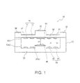
- Fig. 1 is a cross-sectional view showing a non-voltage application state of an optical filter according to an embodiment of the invention.
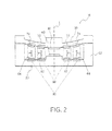
- Fig. 2 is a cross-sectional view showing a voltage application state of the optical filter shown in Fig. 1 .
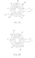
- Fig. 3A is a plan view of a lower electrode
- Fig. 3B is a plan view of an upper electrode of the embodiment.
- Figs. 4A and 4B are plan views of the lower and upper electrodes in an overlapping state viewed from the side of a second substrate.
- Fig. 5 is a plan view showing a wiring layout of first through fourth lead wires viewed from the side of the second substrate through the second substrate.
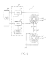
- Fig. 6 is a block diagram of an applied voltage control system of the optical filter.
- Fig. 7 is a characteristics table showing an example of voltage table data.
- Fig. 8 is a timing chart of voltage application realized with the voltage table data.
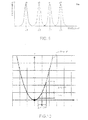
- Fig. 9 is a characteristics chart showing a relationship between a gap between first and second reflecting films of the optical filter and a transmission peak wavelength.
- Fig. 10 is a characteristics chart showing a relationship between an electrical potential difference between the first and second electrodes and the electrostatic attractive force.
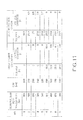
- Fig. 11 is a characteristics table showing data of the embodiment regarding the electrical potential difference, the gap, and the variable wavelength shown in Fig. 7 .
- Fig. 12 is a characteristics chart showing a relationship between the applied voltage and the gap shown in Fig. 11 .
- Fig. 13 is a characteristics chart showing a relationship between the applied voltage and the transmission peak wavelength shown in Fig. 11 .
- Figs. 14A and 14B are plan views showing first and second electrodes of a comparative example.
- Fig. 15 is a characteristics table showing data of the comparative example related to the electrical potential difference, gap, and variable wavelength.
- Fig. 16 is a characteristics chart showing a relationship between the applied voltage and the gap shown in Fig. 15 .
- Fig. 17 is a characteristics chart showing a relationship between the applied voltage and the transmission peak wavelength shown in Fig. 15 .
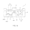
- Fig. 18 is a cross-sectional view showing non-voltage application state of an optical filter according to another embodiment of the invention.
- Fig. 19 is a block diagram of an analytical instrument of still another embodiment of the invention.
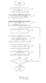
- Fig. 20 is a flowchart showing spectrometric measurement operation in the instrument shown in Fig. 19 .
- Fig. 21 is a block diagram of an optical apparatus of still another embodiment of the invention.
- Fig. 1 is a cross-sectional view of an optical filter according to the present embodiment in a non-voltage application state
- Fig. 2 is a cross-sectional view thereof in a voltage application state.
- the optical filter 10 shown in Figs. 1 and 2 includes a first substrate 20 and a second substrate 30 opposed to the first substrate 20. Although in the present embodiment a fixed substrate is used as the first substrate 20, and a movable substrate or diaphragm is used as the second substrate 30, it is sufficient that either one or both of the substrates can move.
- a support section 22 formed, for example, integrally with the first substrate 20, and for movably supporting the second substrate 30.
- the support section 22 can also be provided to the second substrate 30, or can be formed separately from the first and second substrates 20, 30.
- the first and second substrates 20, 30 are each made of various types of glass such as soda glass, crystalline glass, quartz glass, lead glass, potassium glass, borosilicate glass, or alkali-free glass, a quartz crystal, or the like.
- glass containing alkali metal such as sodium (Na) or potassium (K) is preferable, and by forming the substrates 20, 30 using such glass materials, the adhesiveness with reflecting films 40, 50 and electrodes 60, 70 described later, and the bonding strength between the substrates can be improved.
- these two substrates 20, 30 are bonded by, for example, surface activated bonding with a plasma-polymerized film to thereby be integrated with each other.
- Each of the first and second substrates 20, 30 is formed to have a square shape, for example 10mm on a side, and the greatest diameter of the portion functioning as a diaphragm is, for example, 5mm.
- the first substrate 20 is formed by etching a glass substrate formed to have a thickness of, for example, 500 ⁇ m.
- the first substrate 20 is provided with a first reflecting film 40 having, for example, a circular shape formed on a first opposed surface 20A1 at a central portion of the opposed surface opposed to the second substrate 30.
- the second substrate 30 is formed by etching a glass substrate formed to have a thickness of, for example, 200 ⁇ m.
- the second substrate 30 is provided with a second reflecting film 50 having, for example, a circular shape opposed to the first reflecting film 40 formed at a central position of an opposed surface 30A opposed to the first substrate 20.
- first and second reflecting films 40, 50 are each formed to have, for example, a circular shape with a diameter of about 3mm.
- the first and second reflecting films 40, 50 are each a reflecting film formed of an AgC single layer, and can be provided respectively to the first and second substrates 20, 30 by a method such as sputtering.
- the AgC single layer reflecting film is formed to have a thickness dimension of, for example, 0.03 ⁇ m.
- a dielectric multilayer film obtained by stacking laminated films of, for example, TiO 2 and SiO 2 , which can perform the dispersion operation in a narrower wavelength band, but has a higher transmittance of the dispersed light beams, a narrower half-value width of the transmittance, and more preferable resolution compared to the AgC single layer reflecting film.
- antireflection films AR
- the antireflection films are each formed by alternately stacking low refractive index films and high refractive index films, and decrease the reflectance to the visible light on the interfaces of the first and second substrates 20, 30 while increasing the transmittance thereof.
- the first and second reflecting films 40, 50 are disposed so as to be opposed to each other via a first gap G1 in the non-voltage application state shown in Fig. 1 . It should be noted that although in the present embodiment a fixed mirror is used as the first reflecting film 40 and a movable mirror is used as the second reflecting film 50, it is possible to make either one or both of the first and second reflecting films 40, 50 movable in accordance with the configuration of the first and second substrates 20, 30 described above.
- a second opposed surface 20A2 which is located on the periphery of the first reflecting film 40 and on the periphery of the first opposed surface 20A1 of the first substrate 20 in the plan view, is provided with, for example, a lower electrode 60.
- the opposed surface 30A of the second substrate 30 is provided with an upper electrode 70 so as to correspond to the lower electrode 60.
- the lower electrode 60 and the upper electrode 70 are disposed so as to be opposed to each other via a second gap G2. It should be noted that the surfaces of the lower and upper electrodes 60, 70 can be covered by an insulating film.
- the surface of the first substrate 20 opposed to the second substrate 30 includes the first opposed surface 20A1 provided with the first reflecting film 40 and the second opposed surface 20A2 disposed in the periphery of the first opposed surface 20A1 in the plan view, and provided with the lower electrode 60.
- the first opposed surface 20A1 and the second opposed surface 20A2 can be coplanar with each other, in the present embodiment there is a step between the first opposed surface 20A1 and the second opposed surface 20A2, and the first opposed surface 20A1 is placed nearer to the second substrate 30 than the second opposed surface 20A2.
- the upper electrode 70 is also divided into third and fourth electrodes 72, 74.
- the third and fourth electrodes 72, 74 are not necessarily set to the common electrodes having the same electrical potential, but the structure in which the third electrode 72 and the fourth electrode 74 are electrically isolated (independently controllable) can be adopted.
- the third electrode 72 and the fourth electrode 74 have the structure shown in Fig. 4A . Further, in the structure of the lower electrode 60 and the upper electrode 70, it is sufficient that the electrical potential difference between the first electrode 62 and the third electrode 72 and the electrical potential difference between the second electrode 64 and the fourth electrode 74 can be controlled independently. It should be noted that if K ⁇ 3 is satisfied, the relationship between the first and second electrodes 62, 64 described below can be applied to any two segment electrodes adjacent to each other.
- the first and second substrates 20, 30 have respective areas where the reflecting films (the first and second reflecting films 40, 50) are respectively formed and respective areas where the electrodes (the lower and upper electrodes 60, 70) are respectively formed as areas different from each other in the plan view, and there is no chance of stacking the reflecting film and the electrode with each other as described in Document 1. Therefore, even if at least either one (the second substrate 30 in the present embodiment) of the first and second substrates 20, 30 is formed as a movable substrate, the reflecting film and the electrode are not stacked with each other, and therefore, the movable substrate can be assured to be easy to deflect.
- the optical filter 10 since the reflecting films are not formed on the lower and upper electrodes 60, 70, even if the optical filter 10 is used as a transmissive or reflecting variable wavelength interference filter, the restriction that light transmissive electrodes are used as the lower and upper electrodes 60, 70 does not arise. It should be noted that since even the light transmissive electrode affects the transmission characteristics, by eliminating the formation of the reflecting film on the lower and upper electrodes 60, 70, the optical filter 10 as a transmissive variable wavelength interference filter can be provided with desired transmission characteristics.
- the first gap G1 between the first and second reflecting films 40, 50 can be varied so as to have a value smaller than the initial gap.
- a first gap variable drive section (an electrostatic actuator) 80 composed of the first electrode 62 and the upper electrode 70 opposed thereto
- a second gap variable drive section (an electrostatic actuator) 90 composed of the second electrode 64 and the upper electrode 70 opposed thereto are driven independently.
- the plurality (K) of gap variable drive sections 80, 90 independent of each other disposed only in the periphery of the first and second reflecting films 40, 50 in the plan view, and varying two parameters, namely the values of the voltages applied respectively to the K segment electrodes 62, 64 and the number of segment electrodes selected for applying the voltage among the K segment electrodes 62, 64, the size of the gap between the first and second reflecting films 40, 50 is controlled.
- the maximum value of the applied voltage is Vmax, and the gap can be varied in N levels.
- the lower electrode is not divided into a plurality of segments, it is necessary to divide the maximum voltage Vmax into N to thereby assign the applied voltages.
- the minimum value of the voltage variation between the applied voltages different from each other is ⁇ V1min.
- the applied voltage to each of the K segment electrodes can be assigned by dividing the maximum voltage Vmax into averagely (N/K) .
- the minimum value of the voltage variation between the applied voltages different from each other applied to the same segment electrode with respect to each of the K segment electrodes is ⁇ Vkmin. In this case, it is obvious that ⁇ V1min ⁇ Vkmin is true.
- the gap variation can be reduced even when the applied voltages to the K (first and second) electrodes 62, 64 vary in a certain extent due to the noise depending on the power supply variation and the environment. In other words, the sensitivity to the noise becomes low, or the voltage sensitivity becomes lower.
- the gap control with high accuracy becomes possible, and it is not necessarily required to perform the feedback control on the gap, which is required in Document 1. Further, even if the feedback control is performed on the gap, since the sensitivity to the noise is low, early settling can be achieved.
- an area where the upper electrode 70 is formed is formed as a thin-wall section 34 with a thickness dimension of, for example, 50 ⁇ m as shown in Fig. 1 .
- the thin-wall section 34 is formed to have a wall thickness thinner than a thick-wall section 32 of the area where the second reflecting film 50 is disposed and a thick-wall section 36 of the area having contact with the support section 22.
- the thick-wall section 32 is formed in a first area where the second reflecting film 50 is disposed, and the thin-wall section 34 is formed in a second area where the upper electrode 70 is formed.
- the thick-wall section 32 difficult to bend while assuring the bendability with the thin-wall section 34, it becomes possible to vary the gap while keeping the flatness of the second reflecting film 50.
- the (K) gap variable drive sections independent of each other are each constituted with an electrostatic actuator composed of a pair of electrodes, it is also possible to replace at least one of those electrostatic actuators with another actuator such as a piezoelectric element. It should be noted that the electrostatic actuator for providing attractive force in a non-contact manner causes little interference between gap variable drive sections, and is therefore suitable for controlling the gap with high accuracy.
- the piezoelectric element which is not driven, acts as what hinders the gap variation caused by the other piezoelectric element, which is driven, and a harmful effect is caused in the method of driving two or more gap variable drive sections independently of each other.
- the plurality of gap variable drive sections is preferably composed of the electrostatic actuators.
- the K segment electrodes 62, 64 constituting the lower electrode 60 can be arranged to have ring-like shapes concentric with each other around the center of the first reflecting film 40.
- the first electrode 62 has a first ring-like electrode section 62A
- the second electrode 64 has a second ring-like electrode section 64A outside the first ring-like electrode section 62A
- each of the ring-like electrode sections 62A, 64A is formed to have the concentric ring-like shape with respect to the first reflecting film.
- ring-like shape and a “ring shape” are terms not limited to the shape of an endless ring, but includes a discontinuous ring shape, and are not limited to the shape of a circular ring, but includes the shapes of rectangular ring, polygonal ring, and so on.
- the first and second electrodes 62, 64 are in an axisymmetric arrangement with respect to the center line L of the first reflecting film 40. According to this configuration, since the electrostatic attractive forces F1, F2 acting between the lower and upper electrodes 60, 70 in response to application of the voltages acts thereon axisymmetrically with respect to the center line L of the first reflecting film 40, parallelism between the first and second reflecting films 40, 50 is enhanced.
- the ring width W2 of the second electrode 64 can be set larger than the ring width W1 of the first electrode 62 (W2>W1) . This is because the electrostatic attractive force is proportional to the area of the electrode, and it is required that the electrostatic attractive force F2 generated by the second electrode 64 is stronger than the electrostatic attractive force F1 generated by the first electrode 62.
- the second electrode 64 located outside is disposed nearer to the support section 22 of the substrates functions as a hinge section compared to the first electrode 62. Therefore, it is required for the second electrode 64 to generate the electrostatic attractive force F2 strong enough to overcome the resistive force at the support section (the hinge section) 22.
- the second electrode 64 located outside is driven prior to the first electrode 62 as described later, since the initial gap G2 between the second electrode 64 and the upper electrode 70 is large, it is advantageous in view of the fact that it is possible to make the area of the second electrode 64 larger to thereby increase the electrostatic attractive force F2 generated there. On that occasion, since the gap is made smaller when starting to drive the first electrode 62 located inside as long as the drive state of the second electrode 64 is maintained, there is no harmful effect on driving if the ring width W1 of the first electrode 62 is small.
- a first lead wire 62B is connected to the first electrode 62
- a second lead wire 64B is connected to the second electrode 64.
- the first and second lead wires 62B, 64B are formed so as to extend in radial directions from the center of the first reflecting film 40, for example.
- the first lead wire 62B extending from the first electrode 62 located inside is drawn to the outside of the second electrode 64 via the first slit 64C provided to the second electrode 64 located outside.
- first and second electrodes 62, 64 respectively have the ring-like electrode sections 62A, 64A, a taking-cut path for the first lead wire 62B of the first electrode 62 located inside can easily be assured by the first slit 64C provided to the second electrode 64 located outside.
- the upper electrode 70 disposed on the second substrate 30 can be formed in an area of the second substrate 30 including an area opposed to the lower electrode 60 (the first and second electrodes 62, 64) provided to the first substrate 20.
- the upper electrode 70 a common electrode set to the same voltage, it is possible to form the upper electrode 70 as, for example, a mat electrode.
- the upper electrode 70 disposed on the second electrode 30 displaced with respect to the first substrate 20 as in the present embodiment can be divided into K segment electrodes similarly to the lower electrode 60.
- the K segment electrodes can also be arranged to have concentric ring-like shapes with respect to the center of the second reflecting film 50. According to this configuration, since the area of the electrode provided to the second substrate 30, which is movable, is reduced to the necessity minimum, the rigidity of the second substrate 30 is reduced, and the bendability can be assured.
- the K segment electrodes constituting the upper electrode 70 can include the third electrode 72 and the fourth electrode 74.
- the third electrode 72 has a third ring-like electrode section 72A
- the fourth electrode 74 has a fourth ring-like electrode section 74A outside the third ring-like electrode section 72A
- each of the ring-like electrode sections 72A, 74A is formed to have the concentric ring-like shape with respect to the second reflecting film.
- the meaning of the "concentric ring-like shape" is the same as used for the lower electrode 60.
- the third electrode 72 corresponds to the first electrode 62
- the fourth electrode 74 corresponds to the second electrode 64. Therefore, in the present embodiment, the ring width (equal to the ring width W2 of the second electrode 64) of the fourth electrode 74 is larger than the ring width (equal to the ring width W1 of the first electrode 62) of the third electrode 72.
- third and fourth lead electrodes 76A, 76B are formed so as to extend from the center of the second reflecting film 50 in radial directions, for example.
- Each of the third and fourth lead electrodes 76A, 76B is electrically connected to both of the third electrode 72 located inside and the fourth electrode 74 located outside.
- the wiring resistance can be reduced by providing two or more lead electrodes to thereby improve the charging/discharging rate of the common electrode.
- Fig. 4A shows an overlapping state in a plan view of the lower and upper electrodes 60, 70 of the present embodiment viewed from the side of the second substrate 30.
- the lower electrode 60 located on the lower side does not appear in the plan view thereof viewed from the side of the second substrate 30. Only the first and second lead wires 62B, 64B of the lower electrode 60 located on the lower side appear in the plan view viewed from the side of the second substrate 30 as indicated by hatching.
- the first lead wire 62B is opposed to the opposed area 74A1 of the third ring-like electrode section 74A in an intermediate area 62B1 thereof.
- the electrostatic attractive force F2 (see Fig. 2 ) based on the voltage applied to the second electrode 64 does not act in the area of the slit 64C.
- the electrostatic attractive force F1 (see Fig. 2 ) acting between the first lead wire 62B having the same electrical potential as the first electrode 62 located inside and the fourth electrode 74 located outside can be generated in the first slit 64C.
- uniform electrostatic attractive force can be generated in substantially the whole circumference (including the opposed area 74A1 to the first slit 64C) of the fourth electrode 74 located outside.
- Fig. 4B shows an overlapping state in a plan view of the lower and upper electrodes 60, 70' of a modified example viewed from the side of the second substrate 30.
- the upper electrode 70' shown in Fig. 4B is different from the upper electrode 70 shown in Fig. 4A in the point that the fourth electrode 74 is further provided with a second slit 78 for making the fourth ring-like electrode section 74' discontinuous at the position opposed to the first slit 64C of the lower electrode 60.
- the upper electrode 70' shown in Fig. 4B is the same as the upper electrode 70 shown in Fig. 4A .
- the electrode opposed to the first lead wire 62B is eliminated. Therefore, it is possible to prevent unwanted electrostatic attractive force acting between the first lead wire 62B having the same electric potential as the first electrode 62 located inside and a fourth electrode 74' located outside from being generated in the first slit 64C when driving the first electrode 62 located inside, for example.
- Fig. 5 is a plan view viewed from the side of the second substrate 30 through the second substrate 30, and shows a wiring layout of the first through fourth lead wires 62B, 64B, 76A, and 76B.
- at least one of the first and second substrates 20, 30 is formed as a rectangular substrate having first and second diagonal lines.
- each of the first and second substrates 20, 30 is formed to have a square shape, for example 10mm on a side.
- the second lead wire 64B extends on the first diagonal line in a second direction D2 which is the reverse direction to the first direction D1.
- the third lead wire 76A extends in a third direction D3 along the second diagonal line.
- the fourth lead wire 76B extends on the second diagonal line in a fourth direction D4 which is the reverse direction to the third direction D3.
- first through fourth external connection electrode sections 101 through 104 located at four corners of the rectangular substrates 20, 30 in the plan view to which the first through fourth lead wires 62B, 64B, 76A, and 76B are connected respectively.
- the first and second lead wires 62B, 64B provided to the first substrate 20 and the third and fourth lead wires 76A, 76B provided to the second substrate 30 do not overlap with each other in the plan view, and therefore, no parallel electrodes are constituted. Therefore, the wasteful electrostatic attractive force is hardly generated between the first and second lead wires 628, 64B and the third and fourth lead wires 76A, 76B, and further the wasteful capacitance can be reduced. Further, the wiring lengths of the first through fourth lead wires 62B, 64B, 76A, and 76B respectively to the first through fourth external connection electrode sections 101 through 104 become the shortest.
- the wiring resistances and the wiring capacitances of the first through fourth lead wires 62B, 64B, 76A, and 76B are reduced, and the charging/discharging rate of the first through fourth electrodes 62, 64, 72, and 74 can be raised.
- first through fourth lead wires 62B, 64B, 76A, and 76B it is also possible to adopt a structure in which the first substrate has a first imaginary straight line and a second imaginary straight line intersecting the first imaginary straight line, the first lead wire 62B extends in a first direction along the first imaginary straight line, the second lead wire 64B extends in a second direction along the first imaginary straight line and opposite to the first direction, the third lead wire 76A extends in a third direction along the second imaginary straight line, and the fourth lead wire 76B extends in a fourth direction along the second imaginary straight line and opposite to the third direction.
- first through fourth external connection electrode sections 101 through 104 it is also possible to provide the first through fourth external connection electrode sections 101 through 104 to either one of the first and second substrates 20, 30, or to provide some of the first through fourth external connection electrodes 101 through 104 and the rest thereof to the respective substrates 20, 30.
- the lead wire provided to the other of the first and second substrates 20, 30 can be connected to the external connection electrode section provided to the one of the substrates via a conductive paste or the like.
- the first through fourth external connection electrode sections 101 through 104 are connected to the outside via connection sections such as lead wires or wire bonding.
- first through fourth lead wires 62B, 648, 76A, and 76B can intersect, for example, a plasma polymeric film for bonding the first and second substrates 20, 30 to each other.
- first through fourth lead wires 62B, 642, 76A, and 76B can intersect, for example, a plasma polymeric film for bonding the first and second substrates 20, 30 to each other.
- Fig. 6 is a block diagram of an applied voltage control system of the optical filter 10.
- the optical filter 10 has an electrical potential difference control section 110 for controlling the electrical potential difference between the lower electrode 60 and the upper electrode 70.
- the electrical potential control section 110 varies the applied voltages to the first and second electrodes 62, 64 as the K segment electrodes constituting the lower electrode 60 to thereby respectively control an inner electrical potential difference ⁇ Vseg1 and an outer electrical potential difference ⁇ Vseg2 between the respective first and second electrodes 62, 64 and the upper electrode 70.
- the upper electrode 70 can apply the common voltage other than the ground voltage, and on that occasion, it is possible for the electrical potential difference control section 110 to control application/non-application of the common voltage to the upper electrode 70.
- the electrical potential difference control section 110 includes a first electrode drive section connected to the first electrode 62 such as a first digital-analog converter (DAC1) 112, a second electrode drive section connected to the second electrode 64 such as a second digital-analog converter (DAC2) 114, and a digital control section 116 for performing control, such as digital control, on the digital-analog converters.
- the first and second digital-analog converters 112, 114 are supplied with voltages from a power supply 120.
- the first and second digital-analog converters 112, 114 are supplied with the voltages from the power supply 120, and at the same time output analog voltages corresponding to the digital values from the digital control section 116.
- the power supply 120 what is implemented in an analytical instrument or an optical apparatus to which the optical filter 10 is mounted can be used, and further, a power supply dedicated to the optical filter 10 can also be used.
- Fig. 7 is a characteristics table showing an example of voltage table data, which is original data of the control in the digital control section 116 shown in Fig. 6 .
- the voltage table data can be provided to the digital control section 116 itself, or implemented in the analytical instrument or the optical apparatus to which the optical filter 10 is mounted.
- the electrical potential difference control section 110 sets the voltage values to the respective K segment electrodes (the first and second electrodes 62, 64) in accordance with the voltage table data shown in Fig. 7 , and then applies the voltage values to the respective K segment electrodes (the first and second electrodes 62, 64).
- Fig. 8 is a timing chart of the voltage application realized by performing the drive in the order of the data number of the voltage table data shown in Fig. 7 .
- the optical filter 10 can realize the wavelength transmission characteristics shown in Fig. 9.
- Fig. 9 shows the wavelength transmission characteristics in the case of varying the dimension of the first gap G1 between the first and second reflecting films 40, 50 in a range of, for example, g0 through g3.
- the transmission peak wavelength is determined in accordance with the dimension of the first gap G1.
- the light beam having the wavelength ⁇ which fails to satisfy the condition that the value obtained by multiplying the half wavelength ( ⁇ /2) by an integer (n) is equal to the dimension of the first gap G1, interferes itself to be attenuated in the process of being multiply-reflected by the first and second reflecting films 40, 50, and is never transmitted.
- the light beam transmitted through the optical filter 10 varies in the wavelength, namely the transmission peak wavelength, sequentially to ⁇ 0, ⁇ 1, ⁇ 2, and then ⁇ 3 ( ⁇ 0> ⁇ 1> ⁇ 2> ⁇ 3) so as to be shortened.
- L, M, and N can arbitrarily be changed, the integers satisfying L ⁇ 3, M ⁇ 3, and N ⁇ 6 are preferable. If the integers satisfying L ⁇ 3, M ⁇ 3 , and N ⁇ 6 are used, it is possible to switch the inner electrical potential difference ⁇ Vseg1 and the outer electrical potential difference ⁇ Vseg2 set respectively to the first and second electrodes 62, 64 from the first electrical potential difference ⁇ V1 to the second electrical potential difference ⁇ V2 larger than the first electrical potential difference ⁇ V1, and then the third electrical potential difference ⁇ V3 larger than the second electrical potential difference ⁇ V2.
- the electrical potential difference control section 110 firstly applies the voltages VO1 through VO5 sequentially to the second electrode 64 located outside. Since the upper electrode 70 is set to 0V, the electrical potential difference between the upper electrode 70 and the second electrode 64, namely the outer electrical potential difference Vseg2, can sequentially be increased to the first electrical potential difference VO1, the second electrical potential difference VO2, the third electrical potential difference VO3, the fourth electrical potential difference VO4, and then the fifth electrical potential difference VO5. Thus, the dimension of the first gap G1 between the first and second reflecting films 40, 50 is sequentially reduced in such a manner as g0 ⁇ g1 ⁇ g2 ⁇ g3 ⁇ g4. As a result, the wavelength ⁇ of the light beam transmitted through the optical filter 10, namely the transmission peak wavelength, sequentially varies so as to be shortened in such a manner as ⁇ 0 ⁇ 1 ⁇ 2 ⁇ 3 ⁇ 4.
- the electrical potential difference control section 110 sequentially applies the voltages VI1 through VI4 to the first electrode 62 located inside while keeping the application of the maximum applied voltage VO5 to the second electrode 64. Since the upper electrode 70 is set to 0V, the electrical potential difference between the upper electrode 70 and the first electrode 62, namely the inner electrical potential difference Vseg1, can sequentially be increased to the first electrical potential difference VI1, the second electrical potential difference VI2, the third electrical potential difference VI3, and then the fourth electrical potential difference VI4. Thus, the dimension of the first gap G1 between the first and second reflecting films 40, 50 is sequentially reduced in such a manner as g5 ⁇ g6 ⁇ g7 ⁇ g8. As a result, the wavelength ⁇ of the light beam transmitted through the optical filter 10, namely the transmission peak wavelength, sequentially varies so as to be shortened in such a manner as ⁇ 5 ⁇ 6 ⁇ 7 ⁇ 8.
- the electrical potential difference control section 110 switches the outer electrical potential difference Vseg2 at least from the first electrical potential difference VO1 to the second electrical potential difference VO2 larger than the first electrical potential difference VO1, and further the third electrical potential difference VO3 larger than the second electrical potential difference VO2 and further switches the inner electrical potential difference Vseg1 at least from the first electrical potential difference VI1 to the second electrical potential difference VI2 larger than the first electrical potential difference VI1, and further the third electrical potential difference VI3 larger than the second electrical potential difference VI2, it is possible to suppress the damped free vibration of the second substrate 30, the movable substrate, and thus the prompt wavelength varying operation can be performed.
- the electrical potential difference control section 110 applies three or more voltage values (voltage of 0 can be included) to each of the first and second electrodes 62, 64, namely applies at least the first segment voltage VI1, the second segment voltage VI2, and the third segment voltage VI3 to the first electrode 62, and applies at least the first segment voltage VO1, the second segment voltage VO2, and the third segment voltage VO3 to the second electrode 64. Therefore, it becomes possible to vary the gap in three or more levels only by driving either one of the first and second electrodes 62, 64, and therefore, it can be prevented to unnecessarily increase the number of segment electrodes of the lower electrode 60.
- the electrical potential difference control section 110 can make the absolute value of the difference between the second electrical potential difference and the third electrical potential difference smaller than the absolute value of the difference between the first electrical potential difference and the second electrical potential difference with respect to each of the inner electrical potential difference Vseg1 and the outer electrical potential difference Vseg2. Since in the present embodiment the upper electrode 70 is fixed to the common voltage of 0V, the absolute value of the difference between the first electrical potential difference and the second electrical potential difference as the outer electrical potential difference Vseg2, for example, is equivalent to the voltage variation ⁇ VO1 between the first segment voltage VO1 and the second segment voltage VO2 applied to the second electrode 64 as shown in Figs. 7 and 8 . As shown in Figs.
- the voltage variations of the outer electrical potential difference Vseg2 are in a descending relationship of ⁇ VO1> ⁇ VO2> ⁇ VO3> ⁇ VO4, and the voltage variations of the inner electrical potential difference Vseg1 are in a descending relationship of ⁇ VI1> ⁇ VI2> ⁇ VI3.
- ⁇ denotes the dielectric constant
- V denotes the applied voltage
- G denotes an inter-electrode gap
- S denotes the opposed electrode area.
- the electrostatic attractive force F is proportional to the square of the electrical potential difference (the applied voltage V to the lower electrode 60 in the present embodiment) between the lower and upper electrodes 60, 70.
- the absolute value ⁇ V2 of the difference between the second electrical potential difference and the third electrical potential difference is smaller than the absolute value ⁇ A1 of the difference between the first electrical potential difference and the second electrical potential difference.
- the electrical potential difference control section 110 can set the period during which the electrical potential difference is set to the second electrical potential difference longer than the period during which the electrical potential difference is set to the first electrical potential difference, and the period during which the electrical potential difference is set to the third electrical potential difference longer than the period during which the electrical potential difference is set to the second electrical potential difference with respect to each of the inner electrical potential difference Vseg1 and the outer electrical potential difference Vseg2.
- the present embodiment as shown in Fig.
- the period TO2 of the second electrical potential difference VO2 is longer than the period TO1 of the first electrical potential difference VO1
- the period TO3 of the third electrical potential difference VO3 is longer than the period TO2 of the second electrical potential difference VO2 and the periods are in an ascending relationship of TO1 ⁇ TO2 ⁇ TC3 ⁇ TO4 ⁇ TO5.
- the period TI2 of the second electrical potential difference VI2 is longer than the period TI1 of the first electrical potential difference VI1
- the period TI3 of the third electrical potential difference VI3 is longer than the period TI2 of the second electrical potential difference VI2
- the periods are in an ascending relationship of TI1 ⁇ TI2 ⁇ TI3 ⁇ TI4.
- the restoring force of the second substrate 30 also increases. Therefore, the time until the second substrate 30 stops becomes longer. In other words, the time until the first gap G1 between the first and second reflecting films 40, 50 settles in place becomes longer.
- the period set for the second electrical potential difference longer than the period set for the first electrical potential difference, and setting the period set for the third electrical potential difference longer than the period set for the second electrical potential difference as in the present embodiment it is possible to settle the first gap G1 at a predetermined value.
- Fig. 11 is a characteristics table showing data of the embodiment regarding the electrical potential difference, the gap, and the variable wavelength shown in Fig. 7 .
- the data numbers 1 through 9 in Fig. 11 correspond to the data numbers 1 through 9 in Fig. 7 .
- Fig. 12 is a characteristics chart showing a relationship between the applied voltage and the gap shown in Fig. 11 .
- Fig. 13 is a characteristics chart showing a relationship between the applied voltage and the transmission peak wavelength shown in Fig. 11 .
- the transmission peak wavelength is made variable in 9 levels from the maximum wavelength ⁇ 0 to the minimum wavelength ⁇ 8 (see also Fig. 13 ).
- the transmission peak wavelength is also shortened by a constant value.
- the dimension of the first gap G1 between the first and second reflecting films 40, 50 is more significantly affected by the electrostatic attractive force F1 based on the inner electrical potential difference Vseg1 than the electrostatic attractive force F2 based on the outer electrical potential difference Vseg2. Therefore, if the inner electrical potential difference Vseg1 is firstly varied, and then the outer electrical potential difference Vseg2 is varied while keeping the inner electrical potential difference Vseg1 at a constant value, since the electrostatic attractive force F1 by the inner electrical potential difference Vseg1 is dominant, the gap between the first and second reflecting films 40, 50 does not vary so largely as the outer electrical potential difference Vseg2 varies. Therefore, in the present embodiment, the outer electrical potential difference Vseg2 is varied first, and then the inner electrical potential difference Vseg1 is varied while keeping the outer electrical potential difference Vseg2 at a constant value.
- the electrical potential difference control section 110 varies the inner electrical potential difference Vseg1 while keeping the outer electrical potential difference Vseg2 at the outer maximum electrical potential difference VO5. According to this process, a further gap variation corresponding to one step from the first gap G1 set by the outer maximum electrical potential difference VO5 becomes possible due to the application of the inner electrical potential difference Vseg1. Moreover, since the outer maximum electrical potential difference VO5 has already been reached, it is not required to further vary the outer electrical potential difference Vseg2 after the inner electrical potential difference Vseg1 is applied. Therefore, when varying the outer electrical potential difference Vseg2, no harmful influence is caused by the dominant electrostatic attractive force F1 based on the inner electrical potential difference Vseg1.
- the electrical potential difference control section 110 set the inner electrical potential difference Vseg1 to the inner maximum electrical potential difference VI4, the first gap G1 between the first and second reflecting films 40, 50 is set to the minimum distance g8.
- the outer maximum electrical potential difference VO5 and the inner maximum electrical potential difference VI4 can be set substantially equal to each other within a range not exceeding the maximum supply voltage Vmax to the electrical potential difference control section 110.
- the outer maximum electrical potential difference VO5 is set to 29.8V not exceeding the maximum supply voltage Vmax (30V)
- the inner maximum electrical potential difference VI4 is also set to 29.3V not exceeding the maximum supply voltage Vmax (30V).
- Fig. 11 although there exists a minute difference of 0.5V between the outer maximum electrical potential difference VO5 and the inner maximum electrical potential difference VI4, it can be said that they are substantially the same.
- the minute difference occurs as a result of the design made under the intention that the transmission peak wavelength is obtained using the full scale (see Figs. 12 and 13 ) of the range not exceeding the maximum supply voltage Vmax (30V) with respect to each of the inner electrical potential difference Vseg1 and the outer electrical potential difference Vseg2. It is possible to strictly conform the outer maximum electrical potential difference VO5 and the inner maximum electrical potential difference VI4 to each other by adjusting the area ratio between the first and second electrodes 62, 64 and so on. However, there is little necessity for strictly conforming them.
- the power supply noise is about 0.1V, it is obvious from the comparison with the comparative example described below that the minimum voltage value ⁇ Vkmin has low sensitivity
- the lower electrode 61 shown in Fig. 14A is used instead of the lower electrode 60 of the present embodiment
- the upper electrode 71 shown in Fig. 14B is used instead of the upper electrode 70 of the present embodiment.
- the lower and upper electrodes 61, 71 of the comparative example are not divided into segments.
- Fig. 15 is a characteristics table showing the data of the electrical potential difference between the lower and upper electrodes 61, 71 shown in Figs. 14A and 14B , and the gap and the variable wavelength obtained therefrom.
- the data numbers 1 through 9 in Fig. 15 correspond to the data numbers 1 through 9 in Fig. 11 .
- Fig. 16 is a characteristics chart showing a relationship between the applied voltage and the gap shown in Fig. 15 .
- Fig. 17 is a characteristics chart showing a relationship between the applied voltage and the transmission peak wavelength shown in Fig. 15 .
- the transmission peak wavelength is made variable in 9 levels from the maximum wavelength ⁇ 0 to the minimum wavelength ⁇ 8 (see also Fig. 16 ).
- the voltage minimum variation between the 9 levels of applied voltage in the case of forming the lower electrode 61 of a unique electrode as in the comparative example is defined as ⁇ V1min.
- the voltage minimum variation ⁇ V1min of the comparative example has high sensitivity to the noise.
- FIG. 18 shows an optical filter 11 different from the optical filter 10 shown in Fig. 1 .
- a first substrate 21 shown in Fig. 18 includes the second opposed surface 20A2 provided with the lower electrode 60 in Fig. 1 , a first surface 20A21 in the periphery of the first opposed surface 20A1 provided with the first reflecting film 40 in a plan view, and a second surface 20A22 disposed in the periphery of the first surface 20A21 in the plan view and different in level from the first surface 20A21.
- the first electrode 62 is disposed on the first surface 20A21
- the second electrode 64 is disposed on the second surface 20A22
- an initial value of a gap G22 between the second electrode 64 and the upper electrode 70 and an initial value of a gap G21 between the first electrode 62 and the upper electrode 70 are different from each other.
- the reason of setting such a relationship as described above is as follows.
- the gap G22 in the initial state which is driven first, and corresponds to the second electrode 64, is reduced by the electrostatic attractive force acting between the second electrode 64 and the upper electrode 70.
- the gap G21 is also narrowed at the same time to be smaller than the initial gap. Therefore, when starting to drive the first electrode 62, the gap G21 is smaller than the initial value.
- the gap G22 in the case of first driving the second electrode 64 is larger than the gap G21 in the case of driving the first electrode 62 later. Therefore, it becomes necessary to set the electrostatic attractive force in the case of first driving the second electrode 64 to be excessively stronger than the electrostatic attractive force in the case in which the first electrode 64 is driven.
- the initial value of the gap G22 it is preferable that to set the initial value of the gap G22 to be smaller than the initial value of the gap G21 as shown in Fig. 18 . It should be noted that when the first electrode 62 is driven first, it is sufficient to set the initial value of the gap G21 to be smaller than the initial value of the gap G22.
- Fig. 19 is a block diagram showing a schematic configuration of a colorimeter as an example of an analytical instrument according to an embodiment of the invention.
- the colorimeter 200 is provided with a light source device 202, a spectral measurement device 203, and a colorimetric control device 204.
- the colorimeter 200 emits, for example, a white light beam from the light source device 202 toward the test object A, and then input the test target light beam, the light beam reflected by the test object A, to the spectral measurement device 203. Subsequently, the colorimeter 200 disperses the test target light beam with the spectral measurement device 203, and then spectral characteristics measurement for measuring the intensity of each of the light beams with respective wavelengths obtained by the dispersion is performed.
- the colorimeter 200 makes the test target light beam as the light beam reflected by the test object A enter the optical filter (an etalon) 10, and then performs the spectral characteristics measurement for measuring the intensity of the light beam transmitted through the etalon 10. Subsequently, the colorimetric control device 204 performs the colorimetric process of the test object A, namely analyzes the wavelengths of the colored light beams included therein, and the proportions of the colored light beams, based on the spectral characteristics thus obtained.
- the light source device 202 is provided with a light source 210 and a plurality of lenses 212 (one of the lenses is shown in Fig. 19 ), and emits a white light beam to the test object A. Further, the plurality of lenses 212 includes a collimator lens, and the light source device 202 modifies the white light beam emitted from the light source 210 into a parallel light beam with the collimator lens, and emits it from the projection lens not shown to the test object A.
- the spectral measurement device 203 is provided with the etalon 10, a light receiving section 220 including light receiving elements, a drive circuit 230, and a control circuit section 240. Further, the spectral measurement device 203 has an entrance optical lens not shown disposed at a position opposed to the etalon 10, the entrance optical lens guiding the reflected light beam (the test target light beam) reflected by the test object A into the inside thereof.
- the light receiving section 220 is composed of a plurality of photoelectric conversion elements (the light receiving elements), and generates an electric signal corresponding to the received light intensity. Further, the light receiving section 220 is connected to the control circuit section 240, and outputs the electric signal thus generated to the control circuit section 240 as a light reception signal. It should be noted that it is possible to constitute an optical filter module by integrating the etalon 10 and the light receiving section (the light receiving elements) 220 as a unit.
- the drive circuit 230 is connected to the lower electrode 60 and the upper electrode 70 of the etalon 10, and the control circuit section 240.
- the drive circuit 230 applies the drive voltage between the lower electrode 60 and the upper electrode 70 based on the drive control signal input from the control circuit section 240 to thereby displace the second substrate 30 to a predetermined displacement position.
- the drive voltage can be applied so that the desired electrical potential difference is caused between the lower electrode 60 and the upper electrode 70, and for example, it is also possible to apply a predetermined voltage to the lower electrode 60 while setting the upper electrode 70 to the ground potential.
- a direct-current voltage is preferably used as the drive voltage.
- the control circuit section 240 controls overall operations of the spectral measurement device 203. As shown in Fig. 19 , the control circuit section 240 is mainly composed of, for example, a CPU 250 and a storage section 260. Further, the CPU 250 performs a spectral measurement process based on various programs and various data stored in the storage section 260.
- the storage section 260 is configured including a recording medium such as a memory or a hard disk drive, and stores the various programs and various data so as to be arbitrarily retrieved.
- the storage section 260 stores a voltage adjustment section 261, a gap measurement section 262, a light intensity recognition section 263, and a measurement section 264 as a program. It should be noted that as described above the gap measurement section 262 can be omitted.
- the storage section 260 stores voltage table data 265 shown in Fig. 7 containing voltage values to be applied to the electrostatic actuators 80, 90 for controlling the spacing of the first gap G1 and the time periods, during which the respective voltage values are applied, in conjunction with each other.
- the colorimetric control device 204 is connected to the spectral measurement device 203 and the light source device 202, and performs the control of the light source device 202 and the colorimetric process based on the spectral characteristics obtained by the spectral measurement device 203.
- a general-purpose personal computer, a handheld terminal, a colorimetric-dedicated computer, and so on can be used as the colorimetric control device 204.
- the colorimetric control device 204 is configured including a light source control section 272, a spectral characteristics obtaining section 270, a colorimetric processing section 271, and so on.
- the light source control section 272 is connected to the light source device 202. Further, the light source control section 272 outputs a predetermined control signal to the light source device 202 based on, for example, a setting input by the user to thereby make the light source device 202 emit a white light beam with a predetermined brightness.
- the spectral characteristic obtaining section 270 is connected to the spectral measurement device 203, and obtains the spectral characteristics input from the spectral measurement device 203.
- the colorimetric processing section 271 performs the colorimetric process for measuring the chromaticity of the test object A based on the spectral characteristics. For example, the colorimetric processing section 271 performs a process of making a graph of the spectral characteristics obtained from the spectral measurement device 203, and then outputting it to an output device such as a printer or a display not shown.
- Fig. 20 is a flowchart showing the spectral measurement operation of the spectral measurement device 203.
- the measurement section 264 measures (step S2) the intensity of the light beam transmitted through the etalon 10 in the initial state, namely the state in which no voltage is applied to the electrostatic actuators 80, 90. It should be noted that it is also possible to previously measure the dimension of the first gap G1 in the initial state, for example, at the time of manufacturing of the spectral measurement device and store it in the storage section 260. Then, the measurement section 264 outputs the intensity of the transmitted light beam and the dimension of the first gap in the initial state obtained here to the colorimetric control device 204.
- the voltage adjustment section 261 retrieves (step S3) the voltage table data 265 stored in the storage section 260. Further, the voltage adjustment section 261 adds (step S4) "1" to the measurement count variable n.
- the voltage adjustment section 261 obtains (step S5) the voltage data of the first and second electrodes 62, 64 and the voltage application period data corresponding to the measurement count variable n from the voltage table data 265. Then, the voltage adjustment section 261 outputs the drive control signal to the drive circuit 230 to thereby perform (step S6) the process of driving the electrostatic actuators 80, 90 in accordance with the data of the voltage table data 265.
- the measurement section 264 performs (step S7) the spectral measurement process at the application time elapse timing. Specifically, the measurement section 264 makes the light intensity recognition section 263 measure the intensity of the transmitted light. Further, the measurement section 264 performs the control of outputting the spectral measurement result, which includes the intensity of the transmitted light beam thus measured and the wavelength of the transmitted light beam in conjunction with each other, to the colorimetric control device 204.
- the measurement of the light intensity it is also possible to store the data of the light intensity of a plurality of times of measurement or all of the times of the measurement in the storage section 260, and then measure the light intensity of each of the turns of the measurement in a lump after the data of the light intensity of a plurality of times of measurement or all of the data of the light intensity has been obtained.
- the CPU 250 determines (step S8) whether or not the measurement count variable n reaches the maximum value N, and if it determines that the measurement count variable n is equal to N, it terminates the series of spectral measurement operation. In contrast, if it is determined in the step S8 that the measurement count variable n is smaller than N, the CPU 250 returns to step S4 and performs the process of adding "1" to the measurement count variable n, and then repeats the process of the steps S5 through S8.
- Fig. 21 is a block diagram showing a schematic configuration of a transmitter of a wavelength division multiplexing communication system as an example of an optical apparatus according to an embodiment of the invention.
- WDM wavelength division multiplexing
- a wavelength division multiplexing transmitter 300 has an optical filter 10 to which a light beam from a light source 301 is input, and a plurality of light beams with respective wavelengths ⁇ 0, ⁇ 1, ⁇ 2, ... is transmitted through the optical filter 10.
- Transmission devices 311, 312, and 313 are provided corresponding to the respective wavelengths.
- Optical pulse signals corresponding to a plurality of channels output from the transmission devices 311, 312 , and 313 are combined by a wavelength division multiplexing device 321 into one signal, and then output to an optical fiber transmission channel 331.
- the invention can also be applied to an optical code division multiplexing (OCDM) transmitter in a similar manner. This is because although in the OCDM the channels are discriminated by pattern matching of encoded optical pulse signals, the optical pulses constituting the optical pulse signals include light components with respective wavelengths different from each other.
- OCDM optical code division multiplexing
Landscapes
- Physics & Mathematics (AREA)
- Spectroscopy & Molecular Physics (AREA)
- General Physics & Mathematics (AREA)
- Optics & Photonics (AREA)
- Mechanical Light Control Or Optical Switches (AREA)
- Spectrometry And Color Measurement (AREA)
- Optical Filters (AREA)
- Investigating Or Analysing Materials By Optical Means (AREA)
- Investigating, Analyzing Materials By Fluorescence Or Luminescence (AREA)
Abstract
Description
- The present invention relates to an optical filter, an optical filter module, an analytical instrument, and an optical apparatus.
- There has been proposed an interference filter having a variable transmission wavelength (
JP-A-11-142752 Fig. 3 ofDocument 1, there are provided a pair of substrate held in parallel to each other, a pair of multilayer films (reflecting films) formed on the pair of substrates so as to be opposed to each other and have a gap with a constant distance, and a pair of electrostatic drive electrodes for controlling the gap. Such a variable wavelength interference filter generates electrostatic attractive force in accordance with a voltage applied to the electrostatic drive electrodes to control the gap, thereby making it possible to vary the center wavelength of the transmission light beam. - However, it is difficult for such a variable wavelength interference filter to obtain a gap amount with accuracy due to a variation in the drive voltage caused by noise or the like.
- An advantage of some aspects of the invention is to provide an optical filter, an optical filter module, an analytical instrument, and an optical apparatus each capable of obtaining the gap amount with accuracy.
- 1. According to one aspect of the invention, there is provided an optical filter including a first substrate, a second substrate opposed to the first substrate, a first reflecting film provided to the first substrate, a second reflecting film provided to the second substrate and opposed to the first reflecting film, a first electrode provided to the first substrate and formed in a peripheral area of the first reflecting film in a plan view, a second electrode provided to the first substrate and formed in a peripheral area of the first electrode in the plan view, a third electrode provided to the second substrate and opposed to the first electrode, and a fourth electrode provided to the second substrate and opposed to the second electrode.
- According to this aspect of the invention, there are provided the third electrode provided to the second substrate and opposed to the first electrode, and the fourth electrode provided to the second substrate and opposed to the second electrode. Thus, as described later, the gap amount can be obtained with better accuracy compared to the configuration of controlling the gap amount between the reflecting films only with a pair of electrodes.
- 2. According to another aspect of the invention, in the optical filter according to the above aspect of the invention, the first electrode and the second electrode are electrically isolated from each other, and the third electrode and the fourth electrode are electrically connected to each other via a connecting section.
- Since the third electrode and the fourth electrode are electrically connected via the connection section, the third electrode and the fourth electrode can be used as a common electrode.
- 3. According to another aspect of the invention, in the optical filter according to the above aspect of the invention, there are further provided a first wire connected to the first electrode, and a second wire connected to the second electrode, the first electrode has a first ring-like shape, the second electrode has a second ring-like shape having a first slit, and a part of the first wire is formed in an area where the first slit is formed.
- Since the second electrode has the second ring-like shape having the first slit, the first wire can be drawn from the first electrode via the first slit.
- 4. According to another aspect of the invention, in the optical filter according to the above aspect of the invention, the third electrode has a third ring-like shape, and the fourth electrode has a fourth ring-like shape.
- Since the third electrode and the fourth electrode each have a ring-like shape, parallelism between the reflecting films can be kept at a high level when controlling the gap.
- 5. According to another aspect of the invention, in the optical filter according to the above aspect of the invention, the third electrode has a third ring-like shape, the fourth electrode has a fourth ring-like shape having a second slit, and the second slit overlaps the first slit in the plan view.
- The second slit overlaps the first slit in the plan view. Therefore, the fourth electrode is not formed above the part of the first wire formed in the area of the first slit. Thus, even if the voltage is applied to the first wire, it is possible to prevent unwanted electrostatic attractive force from being generated between the first wire and the fourth electrode.
- 6. According to another aspect of the invention, in the optical filter according to the above aspect of the invention, there are further provided a third wire connected to the third electrode, and a fourth wire connected to the third electrode.
- Since the third wire and the fourth wire are connected to the third electrode, the wiring resistance can be reduced.
- 7. According to another aspect of the invention, in the optical filter according to the above aspect of the invention, the first substrate has a first diagonal line and a second diagonal line, the first wire extends in a first direction along the first diagonal line, the second wire extends in a second direction along the first diagonal line and reverse to the first direction, the third wire extends in a third direction along the second diagonal line, and the fourth wire extends in a fourth direction along the second diagonal line and reverse to the third direction.
- By thus forming the first wire, the second wire, the third wire, and the fourth wire, the parasitic capacitance between these wires can be reduced.
- 8. According to another aspect of the invention, in the optical filter according to the above aspect of the invention, a ring width of the second electrode is larger than a ring width of the first electrode, and a ring width of the fourth electrode is larger than a ring width of the second electrode.
- Since the second electrode and the fourth electrode are located in an area closer to the junction section between the first substrate and the second substrate, there is required an electrostatic attractive force stronger than the electrostatic attractive force between the first electrode and the second electrode. Therefore, by increasing the ring width of the second electrode and the fourth electrode, the stronger electrostatic attractive force can be generated.
- 9. According to another aspect of the invention, in the optical filter according to the above aspect of the invention, the second substrate includes a first part and a second part having a thickness smaller than a thickness of the first part, the second reflecting film is provided to the first part of the second substrate, and the third electrode and the fourth electrode are provided to the second part of the second substrate.
- Since the third electrode and the fourth electrode are provided to the second part having the thickness smaller than the first part, the first substrate can be moved easily when performing the gap control.
- 10. According to another aspect of the invention, in the optical filter according to the above aspect of the invention, the first substrate includes a first surface and a second surface lower than the first surface, the first reflecting film is provided to the first surface, and the first electrode and the second electrode are provided to the second surface.
- 11. According to another aspect of the invention, in the optical filter according to the above aspect of the invention, there is further provided an electrical potential difference control section adapted to control an electrical potential difference between the first electrode and the third electrode, and an electrical potential difference between the second electrode and the fourth electrode.
- 12. According to another aspect of the invention, in the optical filter according to the above aspect of the invention, the electrical potential difference control section sets an electrical potential difference between the second electrode and the fourth electrode to a first electrical potential difference, and then sets an electrical potential difference between the first electrode and the third electrode to a second electrical potential difference.
- Thus, as described later, the gap control can easily be performed.
- 13. According to another aspect of the invention, in the optical filter according to the above aspect of the invention, the electrical potential difference control section sets the electrical potential difference between the first electrode and the third electrode to the second electrical potential difference in a state of setting the electrical potential difference between the second electrode and the fourth electrode to the first electrical potential difference.
- Since the electrical potential difference control section sets the electrical potential difference between the first electrode and the third electrode to the second electrical potential difference in a state of setting the electrical potential difference between the second electrode and the fourth electrode to the first electrical potential difference, the prompt gap control can be performed as described later.
- 14. According to another aspect of the invention, in the optical filter according to the above aspect of the invention, the electrical potential difference control section sets an electrical potential difference between the second electrode and the fourth electrode to a first electrical potential difference, sets the electrical potential difference between the second electrode and the fourth electrode to a second electrical potential difference larger than the first electrical potential difference after setting the electrical potential difference between the second electrode and the fourth electrode to the first electrical potential difference, sets an electrical potential difference between the first electrode and the third electrode to a third electrical potential difference in a state of setting the electrical potential difference between the second electrode and the fourth electrode to the second electrical potential difference, and sets the electrical potential difference between the first electrode and the third electrode to a fourth electrical potential difference larger than the third electrical potential difference in the state of setting the electrical potential difference between the second electrode and the fourth electrode to the second electrical potential difference after setting the electrical potential difference between the first electrode and the third electrode to the third electrical potential difference.
- Thus, the gap control in larger number of levels can be performed. Further, since the electrical potential difference is changed from the first electrical potential difference to the second electrical potential difference larger than the first electrical potential difference, and is changed from the third electrical potential difference to the fourth electrical potential difference larger than the third electrical potential difference, the prompt gap control can be performed.
- 15. According to another aspect of the invention, in the optical filter according to the above aspect of the invention, a period during which the electrical potential difference between the second electrode and the fourth electrode is set to the second electrical potential difference is longer than a period during which the electrical potential difference between the second electrode and the fourth electrode is set to the first electrical potential difference, and a period during which the electrical potential difference between the first electrode and the third electrode is set to the fourth electrical potential difference is longer than a period during which the electrical potential difference between the first electrode and the third electrode is set to the third electrical potential difference.
- Thus, as described later, it is possible to settle the substrates at the desired gap spacing.
- 16. According to another aspect of the invention, in the optical filter according to the above aspect of the invention, the electrical potential difference control section sets an electrical potential difference between the second electrode and the fourth electrode to a first electrical potential difference, sets the electrical potential difference between the second electrode and the fourth electrode to a second electrical potential difference larger than the first electrical potential difference after setting the electrical potential difference between the second electrode and the fourth electrode to the first electrical potential difference, sets the electrical potential difference between the second electrode and the fourth electrode to a third electrical potential difference larger than the second electrical potential difference after setting the electrical potential difference between the second electrode and the fourth electrode to the second electrical potential difference, sets an electrical potential difference between the first electrode and the third electrode to a fourth electrical potential difference in a state of setting the electrical potential difference between the second electrode and the fourth electrode to the third electrical potential difference, sets the electrical potential difference between the first electrode and the third electrode to a fifth electrical potential difference larger than the fourth electrical potential difference in the state of setting the electrical potential difference between the second electrode and the fourth electrode to the third electrical potential difference after setting the electrical potential difference between the first electrode and the third electrode to the fourth electrical potential difference, and sets the electrical potential difference between the first electrode and the third electrode to a sixth electrical potential difference larger than the fifth electrical potential difference in the state of setting the electrical potential difference between the second electrode and the fourth electrode to the third electrical potential difference after setting the electrical potential difference between the first electrode and the third electrode to the fifth electrical potential difference, an absolute value of a difference between the second electrical potential difference and the third electrical potential difference is smaller than an absolute value of a difference between the first electrical potential difference and the second electrical potential difference, and an absolute value of a difference between the fifth electrical potential difference and the sixth electrical potential difference is smaller than an absolute value of a difference between the fourth electrical potential difference and the fifth electrical potential difference.
- Thus, as described later, it is possible to settle the substrates at the desired gap spacing.
- 17. According to another aspect of the invention, there is provided an optical filter module including any one of the optical filters described above, and a light receiving element adapted to receive a light beam transmitted through the optical filter.
- 18. According to an aspect of the invention, there is provided an analytical instrument including any one of the optical filters described above.
- 19. According to an aspect of the invention, there is provided an optical apparatus including any one of the optical filters described above.
- The invention will be described with reference to the accompanying drawings, wherein like numbers reference like elements.
-
Fig. 1 is a cross-sectional view showing a non-voltage application state of an optical filter according to an embodiment of the invention. -
Fig. 2 is a cross-sectional view showing a voltage application state of the optical filter shown inFig. 1 . -
Fig. 3A is a plan view of a lower electrode, andFig. 3B is a plan view of an upper electrode of the embodiment. -
Figs. 4A and 4B are plan views of the lower and upper electrodes in an overlapping state viewed from the side of a second substrate. -
Fig. 5 is a plan view showing a wiring layout of first through fourth lead wires viewed from the side of the second substrate through the second substrate. -
Fig. 6 is a block diagram of an applied voltage control system of the optical filter. -
Fig. 7 is a characteristics table showing an example of voltage table data. -
Fig. 8 is a timing chart of voltage application realized with the voltage table data. -
Fig. 9 is a characteristics chart showing a relationship between a gap between first and second reflecting films of the optical filter and a transmission peak wavelength. -
Fig. 10 is a characteristics chart showing a relationship between an electrical potential difference between the first and second electrodes and the electrostatic attractive force. -
Fig. 11 is a characteristics table showing data of the embodiment regarding the electrical potential difference, the gap, and the variable wavelength shown inFig. 7 . -
Fig. 12 is a characteristics chart showing a relationship between the applied voltage and the gap shown inFig. 11 . -
Fig. 13 is a characteristics chart showing a relationship between the applied voltage and the transmission peak wavelength shown inFig. 11 . -
Figs. 14A and 14B are plan views showing first and second electrodes of a comparative example. -
Fig. 15 is a characteristics table showing data of the comparative example related to the electrical potential difference, gap, and variable wavelength. -
Fig. 16 is a characteristics chart showing a relationship between the applied voltage and the gap shown inFig. 15 . -
Fig. 17 is a characteristics chart showing a relationship between the applied voltage and the transmission peak wavelength shown inFig. 15 . -
Fig. 18 is a cross-sectional view showing non-voltage application state of an optical filter according to another embodiment of the invention. -
Fig. 19 is a block diagram of an analytical instrument of still another embodiment of the invention. -
Fig. 20 is a flowchart showing spectrometric measurement operation in the instrument shown inFig. 19 . -
Fig. 21 is a block diagram of an optical apparatus of still another embodiment of the invention. - Hereinafter, some preferred embodiments of the invention will be described in detail. It should be noted that the present embodiment explained below does not unreasonably limit the content of the invention as set forth in the appended claims, and all of the constituents set forth in the present embodiments are not necessarily essential as means of the invention for solving the problems.
-
Fig. 1 is a cross-sectional view of an optical filter according to the present embodiment in a non-voltage application state, andFig. 2 is a cross-sectional view thereof in a voltage application state. Theoptical filter 10 shown inFigs. 1 and2 includes afirst substrate 20 and asecond substrate 30 opposed to thefirst substrate 20. Although in the present embodiment a fixed substrate is used as thefirst substrate 20, and a movable substrate or diaphragm is used as thesecond substrate 30, it is sufficient that either one or both of the substrates can move. - In the present embodiment, there is provided a
support section 22 formed, for example, integrally with thefirst substrate 20, and for movably supporting thesecond substrate 30. Thesupport section 22 can also be provided to thesecond substrate 30, or can be formed separately from the first andsecond substrates - The first and
second substrates substrates substrates films electrodes substrates second substrates - The
first substrate 20 is formed by etching a glass substrate formed to have a thickness of, for example, 500µm. Thefirst substrate 20 is provided with a first reflectingfilm 40 having, for example, a circular shape formed on a first opposed surface 20A1 at a central portion of the opposed surface opposed to thesecond substrate 30. Similarly, thesecond substrate 30 is formed by etching a glass substrate formed to have a thickness of, for example, 200µm. Thesecond substrate 30 is provided with a second reflectingfilm 50 having, for example, a circular shape opposed to the first reflectingfilm 40 formed at a central position of anopposed surface 30A opposed to thefirst substrate 20. - It should be noted that the first and second reflecting
films films second substrates films - Further, it is possible to form antireflection films (AR) on the respective surfaces of the first and
second substrates films second substrates - The first and second reflecting
films Fig. 1 . It should be noted that although in the present embodiment a fixed mirror is used as the first reflectingfilm 40 and a movable mirror is used as the second reflectingfilm 50, it is possible to make either one or both of the first and second reflectingfilms second substrates - A second opposed surface 20A2, which is located on the periphery of the first reflecting
film 40 and on the periphery of the first opposed surface 20A1 of thefirst substrate 20 in the plan view, is provided with, for example, alower electrode 60. Similarly, theopposed surface 30A of thesecond substrate 30 is provided with anupper electrode 70 so as to correspond to thelower electrode 60. Thelower electrode 60 and theupper electrode 70 are disposed so as to be opposed to each other via a second gap G2. It should be noted that the surfaces of the lower andupper electrodes - In the present embodiment, the surface of the
first substrate 20 opposed to thesecond substrate 30 includes the first opposed surface 20A1 provided with the first reflectingfilm 40 and the second opposed surface 20A2 disposed in the periphery of the first opposed surface 20A1 in the plan view, and provided with thelower electrode 60. Although the first opposed surface 20A1 and the second opposed surface 20A2 can be coplanar with each other, in the present embodiment there is a step between the first opposed surface 20A1 and the second opposed surface 20A2, and the first opposed surface 20A1 is placed nearer to thesecond substrate 30 than the second opposed surface 20A2. Thus, the relationship of (first gap G1)<(second gap G2) becomes true. - The
lower electrode 60 is divided into at least K (K is an integer equal to or greater than 2) segment electrodes electrically isolated from each other, and in the present embodiment, thelower electrode 60 has first andsecond electrodes K segment electrodes upper electrode 70 is a common electrode having the same electrical potential. Theupper electrode 70 is also divided into third andfourth electrodes fourth electrodes third electrode 72 and thefourth electrode 74 are electrically isolated (independently controllable) can be adopted. For example, it is also possible that thethird electrode 72 and thefourth electrode 74 have the structure shown inFig. 4A . Further, in the structure of thelower electrode 60 and theupper electrode 70, it is sufficient that the electrical potential difference between thefirst electrode 62 and thethird electrode 72 and the electrical potential difference between thesecond electrode 64 and thefourth electrode 74 can be controlled independently. It should be noted that if K≥3 is satisfied, the relationship between the first andsecond electrodes - In the
optical filter 10 having such a structure, the first andsecond substrates films 40, 50) are respectively formed and respective areas where the electrodes (the lower andupper electrodes 60, 70) are respectively formed as areas different from each other in the plan view, and there is no chance of stacking the reflecting film and the electrode with each other as described inDocument 1. Therefore, even if at least either one (thesecond substrate 30 in the present embodiment) of the first andsecond substrates Document 1, since the reflecting films are not formed on the lower andupper electrodes optical filter 10 is used as a transmissive or reflecting variable wavelength interference filter, the restriction that light transmissive electrodes are used as the lower andupper electrodes upper electrodes optical filter 10 as a transmissive variable wavelength interference filter can be provided with desired transmission characteristics. - Further, in the
optical filter 10 by applying the common voltage (e.g., the ground voltage) to theupper electrode 70 disposed in the periphery of the second reflectingfilm 50 in the plan view, and applying voltages independent of each other to the respectiveK segment electrodes lower electrode 60 disposed in the periphery of the first reflectingfilm 40 in the plan view to thereby act the electrostatic attractive force indicated by the arrow between the opposed electrodes as shown inFig. 2 , the first gap G1 between the first and second reflectingfilms - In other words, as shown in
Fig. 2 showing the optical filter in the voltage application state, a first gap variable drive section (an electrostatic actuator) 80 composed of thefirst electrode 62 and theupper electrode 70 opposed thereto, and a second gap variable drive section (an electrostatic actuator) 90 composed of thesecond electrode 64 and theupper electrode 70 opposed thereto are driven independently. - As described above, by providing the plurality (K) of gap
variable drive sections films K segment electrodes K segment electrodes films - It is difficult to obtain both of the large gap variable range and the low sensitivity to the voltage variation due to noise or the like with the parameter of the type of voltage alone as in
Document 1. By adding the parameter of the number of electrodes as in the present embodiment, it becomes possible to generate more fine-tuned electrostatic attractive force to thereby perform the fine gap adjustment in a larger gap variable range by applying the applied voltage range the same as in the case of controlling it by voltage alone to the individual segment electrodes. - Here, it is assumed that the maximum value of the applied voltage is Vmax, and the gap can be varied in N levels. In the case in which the lower electrode is not divided into a plurality of segments, it is necessary to divide the maximum voltage Vmax into N to thereby assign the applied voltages. On this occasion, it is assumed that the minimum value of the voltage variation between the applied voltages different from each other is ΔV1min. In contrast, in the present embodiment, the applied voltage to each of the K segment electrodes can be assigned by dividing the maximum voltage Vmax into averagely (N/K) . On this occasion, it is assumed that the minimum value of the voltage variation between the applied voltages different from each other applied to the same segment electrode with respect to each of the K segment electrodes is ΔVkmin. In this case, it is obvious that ΔV1min<ΔVkmin is true.
- As described above, if the voltage minimum variation ΔVkmin can be assured to be large, the gap variation can be reduced even when the applied voltages to the K (first and second)
electrodes Document 1. Further, even if the feedback control is performed on the gap, since the sensitivity to the noise is low, early settling can be achieved. - In the present embodiment, in order for assuring bendability of the
second substrate 30 as the movable substrate, an area where theupper electrode 70 is formed is formed as a thin-wall section 34 with a thickness dimension of, for example, 50µm as shown inFig. 1 . The thin-wall section 34 is formed to have a wall thickness thinner than a thick-wall section 32 of the area where the second reflectingfilm 50 is disposed and a thick-wall section 36 of the area having contact with thesupport section 22. In other words, in thesecond substrate 30 thesurface 30A where the second reflectingfilm 50 and theupper electrode 70 are formed is a flat plane, the thick-wall section 32 is formed in a first area where the second reflectingfilm 50 is disposed, and the thin-wall section 34 is formed in a second area where theupper electrode 70 is formed. As described above, by making the thick-wall section 32 difficult to bend while assuring the bendability with the thin-wall section 34, it becomes possible to vary the gap while keeping the flatness of the second reflectingfilm 50. - It should be noted that although in the present embodiment the (K) gap variable drive sections independent of each other are each constituted with an electrostatic actuator composed of a pair of electrodes, it is also possible to replace at least one of those electrostatic actuators with another actuator such as a piezoelectric element. It should be noted that the electrostatic actuator for providing attractive force in a non-contact manner causes little interference between gap variable drive sections, and is therefore suitable for controlling the gap with high accuracy. In contrast thereto, in the case, for example, in which two piezoelectric elements are disposed between the first and
second substrates - As shown in
Fig. 3A , theK segment electrodes lower electrode 60 can be arranged to have ring-like shapes concentric with each other around the center of the first reflectingfilm 40. Specifically, thefirst electrode 62 has a first ring-like electrode section 62A, thesecond electrode 64 has a second ring-like electrode section 64A outside the first ring-like electrode section 62A, and each of the ring-like electrode sections - According to this configuration, as shown in
Fig. 2 , the first andsecond electrodes film 40. According to this configuration, since the electrostatic attractive forces F1, F2 acting between the lower andupper electrodes film 40, parallelism between the first and second reflectingfilms - It should be noted that as shown in
Fig. 3A , the ring width W2 of thesecond electrode 64 can be set larger than the ring width W1 of the first electrode 62 (W2>W1) . This is because the electrostatic attractive force is proportional to the area of the electrode, and it is required that the electrostatic attractive force F2 generated by thesecond electrode 64 is stronger than the electrostatic attractive force F1 generated by thefirst electrode 62. In more detail, thesecond electrode 64 located outside is disposed nearer to thesupport section 22 of the substrates functions as a hinge section compared to thefirst electrode 62. Therefore, it is required for thesecond electrode 64 to generate the electrostatic attractive force F2 strong enough to overcome the resistive force at the support section (the hinge section) 22. Thesecond electrode 64 located outside has a larger diameter than that of thefirst electrode 62 located inside, and therefore, even if the widths are the same (W1=W2), the area of thesecond electrode 64 is larger. Therefore, although it is also possible to make the widths equal to each other (W1=W2), the ring width W2 is made larger to thereby make it possible to further increase the area to increase the electrostatic attractive force F2 generated by thesecond electrode 64. In particular, in the case in which thesecond electrode 64 located outside is driven prior to thefirst electrode 62 as described later, since the initial gap G2 between thesecond electrode 64 and theupper electrode 70 is large, it is advantageous in view of the fact that it is possible to make the area of thesecond electrode 64 larger to thereby increase the electrostatic attractive force F2 generated there. On that occasion, since the gap is made smaller when starting to drive thefirst electrode 62 located inside as long as the drive state of thesecond electrode 64 is maintained, there is no harmful effect on driving if the ring width W1 of thefirst electrode 62 is small. - Here, a
first lead wire 62B is connected to thefirst electrode 62, and asecond lead wire 64B is connected to thesecond electrode 64. The first and secondlead wires film 40, for example. There is provided a first slit 64C for making the second ring-like electrode section 64A of thesecond electrode 64 discontinuous. Thefirst lead wire 62B extending from thefirst electrode 62 located inside is drawn to the outside of thesecond electrode 64 via the first slit 64C provided to thesecond electrode 64 located outside. - As described above, in the case of making the first and
second electrodes like electrode sections first lead wire 62B of thefirst electrode 62 located inside can easily be assured by the first slit 64C provided to thesecond electrode 64 located outside. - The
upper electrode 70 disposed on thesecond substrate 30 can be formed in an area of thesecond substrate 30 including an area opposed to the lower electrode 60 (the first andsecond electrodes 62, 64) provided to thefirst substrate 20. In the case of making the upper electrode 70 a common electrode set to the same voltage, it is possible to form theupper electrode 70 as, for example, a mat electrode. - Alternatively, the
upper electrode 70 disposed on thesecond electrode 30 displaced with respect to thefirst substrate 20 as in the present embodiment can be divided into K segment electrodes similarly to thelower electrode 60. The K segment electrodes can also be arranged to have concentric ring-like shapes with respect to the center of the second reflectingfilm 50. According to this configuration, since the area of the electrode provided to thesecond substrate 30, which is movable, is reduced to the necessity minimum, the rigidity of thesecond substrate 30 is reduced, and the bendability can be assured. - As shown in
Figs. 1 ,2 , and3B , the K segment electrodes constituting theupper electrode 70 can include thethird electrode 72 and thefourth electrode 74. Thethird electrode 72 has a third ring-like electrode section 72A, thefourth electrode 74 has a fourth ring-like electrode section 74A outside the third ring-like electrode section 72A, and each of the ring-like electrode sections lower electrode 60. Thethird electrode 72 corresponds to thefirst electrode 62, and thefourth electrode 74 corresponds to thesecond electrode 64. Therefore, in the present embodiment, the ring width (equal to the ring width W2 of the second electrode 64) of thefourth electrode 74 is larger than the ring width (equal to the ring width W1 of the first electrode 62) of thethird electrode 72. - Further, it is possible to electrically connect the third and
fourth electrodes fourth lead electrodes film 50 in radial directions, for example. Each of the third andfourth lead electrodes third electrode 72 located inside and thefourth electrode 74 located outside. It should be noted that since the third andfourth electrodes fourth electrodes electrodes -
Fig. 4A shows an overlapping state in a plan view of the lower andupper electrodes second substrate 30. InFig. 4A , since the first andsecond electrodes fourth electrodes second electrode 70, thelower electrode 60 located on the lower side does not appear in the plan view thereof viewed from the side of thesecond substrate 30. Only the first and secondlead wires lower electrode 60 located on the lower side appear in the plan view viewed from the side of thesecond substrate 30 as indicated by hatching. Since the third ring-like electrode section 74A of theupper electrode 70 is continuous in the circumferential direction, thefirst lead wire 62B is opposed to the opposed area 74A1 of the third ring-like electrode section 74A in an intermediate area 62B1 thereof. - As shown in
Fig. 3A , in the present embodiment since thesecond electrode 64 located outside out of thelower electrode 60 has a first slit 64C, the electrostatic attractive force F2 (seeFig. 2 ) based on the voltage applied to thesecond electrode 64 does not act in the area of the slit 64C. - On the other hand, since the
first lead wire 62B is disposed in the first slit 64C as shown inFig. 3A , the electrostatic attractive force F1 (seeFig. 2 ) acting between thefirst lead wire 62B having the same electrical potential as thefirst electrode 62 located inside and thefourth electrode 74 located outside can be generated in the first slit 64C. As an advantage of this configuration, in the case of, for example, driving the first andsecond electrodes fourth electrode 74 located outside. -
Fig. 4B shows an overlapping state in a plan view of the lower andupper electrodes 60, 70' of a modified example viewed from the side of thesecond substrate 30. The upper electrode 70' shown inFig. 4B is different from theupper electrode 70 shown inFig. 4A in the point that thefourth electrode 74 is further provided with asecond slit 78 for making the fourth ring-like electrode section 74' discontinuous at the position opposed to the first slit 64C of thelower electrode 60. In other points, the upper electrode 70' shown inFig. 4B is the same as theupper electrode 70 shown inFig. 4A . - According to this configuration, the electrode opposed to the
first lead wire 62B is eliminated. Therefore, it is possible to prevent unwanted electrostatic attractive force acting between thefirst lead wire 62B having the same electric potential as thefirst electrode 62 located inside and a fourth electrode 74' located outside from being generated in the first slit 64C when driving thefirst electrode 62 located inside, for example. -
Fig. 5 is a plan view viewed from the side of thesecond substrate 30 through thesecond substrate 30, and shows a wiring layout of the first through fourthlead wires Fig. 5 , at least one of the first andsecond substrates second substrates first lead wire 62B extends from thefirst electrode 62A along the first diagonal line is a first direction D1, thesecond lead wire 64B extends on the first diagonal line in a second direction D2 which is the reverse direction to the first direction D1. Thethird lead wire 76A extends in a third direction D3 along the second diagonal line. Thefourth lead wire 76B extends on the second diagonal line in a fourth direction D4 which is the reverse direction to the third direction D3. Further, there are disposed first through fourth externalconnection electrode sections 101 through 104 located at four corners of therectangular substrates lead wires - According to this configuration, firstly, the first and second
lead wires first substrate 20 and the third andfourth lead wires second substrate 30 do not overlap with each other in the plan view, and therefore, no parallel electrodes are constituted. Therefore, the wasteful electrostatic attractive force is hardly generated between the first and secondlead wires 628, 64B and the third andfourth lead wires lead wires connection electrode sections 101 through 104 become the shortest. Therefore, the wiring resistances and the wiring capacitances of the first through fourthlead wires fourth electrodes - It should be noted that as the structure of the first through fourth
lead wires first lead wire 62B extends in a first direction along the first imaginary straight line, thesecond lead wire 64B extends in a second direction along the first imaginary straight line and opposite to the first direction, thethird lead wire 76A extends in a third direction along the second imaginary straight line, and thefourth lead wire 76B extends in a fourth direction along the second imaginary straight line and opposite to the third direction. - It should be noted that it is also possible to provide the first through fourth external
connection electrode sections 101 through 104 to either one of the first andsecond substrates external connection electrodes 101 through 104 and the rest thereof to therespective substrates external connection electrodes 101 through 104 to either one of the first andsecond substrates second substrates connection electrode sections 101 through 104 are connected to the outside via connection sections such as lead wires or wire bonding. - Further, the first through fourth
lead wires second substrates lead wires second substrates -
Fig. 6 is a block diagram of an applied voltage control system of theoptical filter 10. As shown in Fig- 6, theoptical filter 10 has an electrical potentialdifference control section 110 for controlling the electrical potential difference between thelower electrode 60 and theupper electrode 70. In the present embodiment, since the upper electrode 70 (the third andfourth electrodes 72, 74) as the common electrode is fixed to a constant common voltage, for example, the ground voltage (0V), the electricalpotential control section 110 varies the applied voltages to the first andsecond electrodes lower electrode 60 to thereby respectively control an inner electrical potential difference ΔVseg1 and an outer electrical potential difference ΔVseg2 between the respective first andsecond electrodes upper electrode 70. It should be noted that theupper electrode 70 can apply the common voltage other than the ground voltage, and on that occasion, it is possible for the electrical potentialdifference control section 110 to control application/non-application of the common voltage to theupper electrode 70. - In
Fig. 6 the electrical potentialdifference control section 110 includes a first electrode drive section connected to thefirst electrode 62 such as a first digital-analog converter (DAC1) 112, a second electrode drive section connected to thesecond electrode 64 such as a second digital-analog converter (DAC2) 114, and adigital control section 116 for performing control, such as digital control, on the digital-analog converters. The first and second digital-analog converters power supply 120. The first and second digital-analog converters power supply 120, and at the same time output analog voltages corresponding to the digital values from thedigital control section 116. As thepower supply 120, what is implemented in an analytical instrument or an optical apparatus to which theoptical filter 10 is mounted can be used, and further, a power supply dedicated to theoptical filter 10 can also be used. -
Fig. 7 is a characteristics table showing an example of voltage table data, which is original data of the control in thedigital control section 116 shown inFig. 6 . The voltage table data can be provided to thedigital control section 116 itself, or implemented in the analytical instrument or the optical apparatus to which theoptical filter 10 is mounted. -
Fig. 7 shows an example with N=9 as the voltage table data for varying the gap between the first and second reflectingfilms second electrodes Fig. 7 , the case in which the respective electrical potential differences between the first andsecond electrodes upper electrode 70 are 0V is not included in the N levels of gap variable range.Fig. 7 shows only the case in which the voltage value other than the voltage value (0V) of the common voltage applied to theupper electrode 70 is applied to at least one of the first andsecond electrodes second electrodes upper electrode 70 are 0V, as the maximum transmission peak wavelength. - The electrical potential
difference control section 110 sets the voltage values to the respective K segment electrodes (the first andsecond electrodes 62, 64) in accordance with the voltage table data shown inFig. 7 , and then applies the voltage values to the respective K segment electrodes (the first andsecond electrodes 62, 64).Fig. 8 is a timing chart of the voltage application realized by performing the drive in the order of the data number of the voltage table data shown inFig. 7 . - As shown in
Figs. 7 and8 , L (=4) levels of voltages (VI1 through VI4; VI1<VI2<VI3<VI4) are applied to thefirst electrode 62, and M (=5) levels of voltages (VO1 through VO5; VO1<VO2<VO3<VO4<VO5) are applied to thesecond electrode 64, thereby varying the first gap G1 between the first and second reflectingfilms - According to the voltage control described above, the
optical filter 10 can realize the wavelength transmission characteristics shown inFig. 9. Fig. 9 shows the wavelength transmission characteristics in the case of varying the dimension of the first gap G1 between the first and second reflectingfilms optical filter 10, when the dimension of the first gap G1 between the first and second reflectingfilms optical filter 10 satisfies the condition that the value obtained by multiplying the half wavelength (λ/2) by an integer (n) is equal to the dimension of the first gap G1 (n×λ=2G1). The light beam having the wavelength λ, which fails to satisfy the condition that the value obtained by multiplying the half wavelength (λ/2) by an integer (n) is equal to the dimension of the first gap G1, interferes itself to be attenuated in the process of being multiply-reflected by the first and second reflectingfilms - Therefore, as shown in
Fig. 9 , by varying the dimension of the first gap G1 between the first and second reflectingfilms optical filter 10 varies in the wavelength, namely the transmission peak wavelength, sequentially to λ0, λ1, λ2, and then λ3 (λ0>λ1>λ2>λ3) so as to be shortened. - Here, although the values of L, M, and N can arbitrarily be changed, the integers satisfying L≥3, M≥3, and N≥6 are preferable. If the integers satisfying L≥3, M≥3 , and N≥6 are used, it is possible to switch the inner electrical potential difference ΔVseg1 and the outer electrical potential difference ΔVseg2 set respectively to the first and
second electrodes - As shown in
Fig. 8 , the electrical potentialdifference control section 110 firstly applies the voltages VO1 through VO5 sequentially to thesecond electrode 64 located outside. Since theupper electrode 70 is set to 0V, the electrical potential difference between theupper electrode 70 and thesecond electrode 64, namely the outer electrical potential difference Vseg2, can sequentially be increased to the first electrical potential difference VO1, the second electrical potential difference VO2, the third electrical potential difference VO3, the fourth electrical potential difference VO4, and then the fifth electrical potential difference VO5. Thus, the dimension of the first gap G1 between the first and second reflectingfilms optical filter 10, namely the transmission peak wavelength, sequentially varies so as to be shortened in such a manner as λ0→λ1→λ2→λ3→λ4. - Subsequently, as shown in
Fig. 8 , the electrical potentialdifference control section 110 sequentially applies the voltages VI1 through VI4 to thefirst electrode 62 located inside while keeping the application of the maximum applied voltage VO5 to thesecond electrode 64. Since theupper electrode 70 is set to 0V, the electrical potential difference between theupper electrode 70 and thefirst electrode 62, namely the inner electrical potential difference Vseg1, can sequentially be increased to the first electrical potential difference VI1, the second electrical potential difference VI2, the third electrical potential difference VI3, and then the fourth electrical potential difference VI4. Thus, the dimension of the first gap G1 between the first and second reflectingfilms optical filter 10, namely the transmission peak wavelength, sequentially varies so as to be shortened in such a manner as λ5→λ6→λ7→λ8. - Since the electrical potential
difference control section 110 switches the outer electrical potential difference Vseg2 at least from the first electrical potential difference VO1 to the second electrical potential difference VO2 larger than the first electrical potential difference VO1, and further the third electrical potential difference VO3 larger than the second electrical potential difference VO2 and further switches the inner electrical potential difference Vseg1 at least from the first electrical potential difference VI1 to the second electrical potential difference VI2 larger than the first electrical potential difference VI1, and further the third electrical potential difference VI3 larger than the second electrical potential difference VI2, it is possible to suppress the damped free vibration of thesecond substrate 30, the movable substrate, and thus the prompt wavelength varying operation can be performed. Moreover, the electrical potentialdifference control section 110 applies three or more voltage values (voltage of 0 can be included) to each of the first andsecond electrodes first electrode 62, and applies at least the first segment voltage VO1, the second segment voltage VO2, and the third segment voltage VO3 to thesecond electrode 64. Therefore, it becomes possible to vary the gap in three or more levels only by driving either one of the first andsecond electrodes lower electrode 60. - The electrical potential
difference control section 110 can make the absolute value of the difference between the second electrical potential difference and the third electrical potential difference smaller than the absolute value of the difference between the first electrical potential difference and the second electrical potential difference with respect to each of the inner electrical potential difference Vseg1 and the outer electrical potential difference Vseg2. Since in the present embodiment theupper electrode 70 is fixed to the common voltage of 0V, the absolute value of the difference between the first electrical potential difference and the second electrical potential difference as the outer electrical potential difference Vseg2, for example, is equivalent to the voltage variation ΔVO1 between the first segment voltage VO1 and the second segment voltage VO2 applied to thesecond electrode 64 as shown inFigs. 7 and8 . As shown inFigs. 7 and8 , the voltage variations of the outer electrical potential difference Vseg2 are in a descending relationship of ΔVO1>ΔVO2>ΔVO3>ΔVO4, and the voltage variations of the inner electrical potential difference Vseg1 are in a descending relationship of ΔVI1>ΔVI2>ΔVI3. - The reason of setting such a relationship as described above is as follows.
- The electrostatic attractive force F can be represented as "F=(1/2)ε(V/G )2S." Here, ε denotes the dielectric constant, V denotes the applied voltage, G denotes an inter-electrode gap, and S denotes the opposed electrode area. According to this formula, the electrostatic attractive force F is proportional to the square of the electrical potential difference (the applied voltage V to the
lower electrode 60 in the present embodiment) between the lower andupper electrodes Fig. 10 is a characteristics chart (the chart showing F=V2) of the electrostatic attractive force F proportional to the square of the electrical potential difference V. As shown inFig. 10 , when switching the electrical potential difference V in the ascending direction to the first electrical potential difference, the second electrical potential difference, and then the third electrical potential difference, if the absolute value ΔV1 of the difference between the first electrical potential difference and the second electrical potential difference and the absolute value ΔV2 of the difference between the second electrical potential difference and the third electrical potential difference are the same (ΔV1=ΔV2 inFig. 10 ), it results that the increment ΔF of the electrostatic attractive force rapidly increases from ΔF1 to ΔF2, which causes an overshoot. - Therefore, it is arranged that the absolute value ΔV2 of the difference between the second electrical potential difference and the third electrical potential difference is smaller than the absolute value ΔA1 of the difference between the first electrical potential difference and the second electrical potential difference. Thus, it is possible to suppress the rapid increase in the electrostatic attractive force when the gap is narrowed to thereby further suppress the overshoot, and thus, the prompter wavelength variation operation can be realized.
- The electrical potential
difference control section 110 can set the period during which the electrical potential difference is set to the second electrical potential difference longer than the period during which the electrical potential difference is set to the first electrical potential difference, and the period during which the electrical potential difference is set to the third electrical potential difference longer than the period during which the electrical potential difference is set to the second electrical potential difference with respect to each of the inner electrical potential difference Vseg1 and the outer electrical potential difference Vseg2. In the present embodiment, as shown inFig. 8 , regarding the outer electrical potential difference Vseg2, the period TO2 of the second electrical potential difference VO2 is longer than the period TO1 of the first electrical potential difference VO1, the period TO3 of the third electrical potential difference VO3 is longer than the period TO2 of the second electrical potential difference VO2 and the periods are in an ascending relationship of TO1<TO2<TC3<TO4<TO5. Similarly, as shown inFig. 8 , regarding the inner electrical potential difference Vseg1, the period TI2 of the second electrical potential difference VI2 is longer than the period TI1 of the first electrical potential difference VI1, the period TI3 of the third electrical potential difference VI3 is longer than the period TI2 of the second electrical potential difference VI2, and the periods are in an ascending relationship of TI1<TI2<TI3<TI4. - When the second electrical potential difference larger than the first electrical potential difference is set, or the third electrical potential difference larger than the second electrical potential difference is set, the restoring force of the
second substrate 30 also increases. Therefore, the time until thesecond substrate 30 stops becomes longer. In other words, the time until the first gap G1 between the first and second reflectingfilms -
Fig. 11 is a characteristics table showing data of the embodiment regarding the electrical potential difference, the gap, and the variable wavelength shown inFig. 7 . The data numbers 1 through 9 inFig. 11 correspond to thedata numbers 1 through 9 inFig. 7 .Fig. 12 is a characteristics chart showing a relationship between the applied voltage and the gap shown inFig. 11 .Fig. 13 is a characteristics chart showing a relationship between the applied voltage and the transmission peak wavelength shown inFig. 11 . - In
Fig. 11 , in order for making the transmission peak wavelength variable in 9 levels from the maximum wavelength λ0 (=700nm) to the minimum wavelength λ8 (=380nm) of the transmission peak wavelength, the first gap G1 between the first and second reflectingfilms Fig. 12 ). In accordance therewith, the transmission peak wavelength is made variable in 9 levels from the maximum wavelength λ0 to the minimum wavelength λ8 (see alsoFig. 13 ). Moreover, inFig. 11 , by setting the 9 levels of gaps g0 through g8 from the maximum gap g0 to the minimum gap g8 at regular intervals (=20nm), the 9 levels of the wavelength λ0 through λ8 from the maximum wavelength λ0 to the minimum wavelength λ8 are also set to have regular intervals (=40nm). By varying the dimension of the first gap G1 between the first and second reflecting films so as to sequentially decrease by a constant amount, the transmission peak wavelength is also shortened by a constant value. - The electrical potential
difference control section 110 sets the outer electrical potential difference Vseg2 sequentially to VO1 (=16.9V), VO2 (=21.4V), VO3 (=25V), VO4 (=27.6V), and then VO5 (=29.8V), and then sets the inner electrical potential difference Vseg1 sequentially to VI1 (=16.4V), VI2 (=22.2V), VI3 (=26.3V), and then VI4 (=29.3V) while keeping the outer electrical potential difference Vseg2 at VO5 (=29.8V). - It should be noted that the dimension of the first gap G1 between the first and second reflecting
films films - After the outer electrical potential difference Vseg2 reaches the outer maximum electrical potential difference VO5 the electrical potential
difference control section 110 varies the inner electrical potential difference Vseg1 while keeping the outer electrical potential difference Vseg2 at the outer maximum electrical potential difference VO5. According to this process, a further gap variation corresponding to one step from the first gap G1 set by the outer maximum electrical potential difference VO5 becomes possible due to the application of the inner electrical potential difference Vseg1. Moreover, since the outer maximum electrical potential difference VO5 has already been reached, it is not required to further vary the outer electrical potential difference Vseg2 after the inner electrical potential difference Vseg1 is applied. Therefore, when varying the outer electrical potential difference Vseg2, no harmful influence is caused by the dominant electrostatic attractive force F1 based on the inner electrical potential difference Vseg1. - When the electrical potential
difference control section 110 set the inner electrical potential difference Vseg1 to the inner maximum electrical potential difference VI4, the first gap G1 between the first and second reflectingfilms difference control section 110. In the present embodiment the maximum supply voltage Vmax (=30V), for example, is supplied to the electrical potentialdifference control section 110 from thepower supply 120 shown inFig. 6 . On this occasion, the outer maximum electrical potential difference VO5 is set to 29.8V not exceeding the maximum supply voltage Vmax (30V), and further the inner maximum electrical potential difference VI4 is also set to 29.3V not exceeding the maximum supply voltage Vmax (30V). - In
Fig. 11 , although there exists a minute difference of 0.5V between the outer maximum electrical potential difference VO5 and the inner maximum electrical potential difference VI4, it can be said that they are substantially the same. The minute difference occurs as a result of the design made under the intention that the transmission peak wavelength is obtained using the full scale (seeFigs. 12 and 13 ) of the range not exceeding the maximum supply voltage Vmax (30V) with respect to each of the inner electrical potential difference Vseg1 and the outer electrical potential difference Vseg2. It is possible to strictly conform the outer maximum electrical potential difference VO5 and the inner maximum electrical potential difference VI4 to each other by adjusting the area ratio between the first andsecond electrodes Fig. 4A , by making the outer maximum electrical potential difference VO5 and the inner maximum electrical potential difference VI4 substantially equal to each other, there is obtained an advantage that even electrostatic attractive force can be generated in almost entire circumference (including the opposed area 74A1 to the first slit 64C) of thefourth electrode 74 located outside. - In the present embodiment the electrical potential
difference control section 110 sequentially applies the voltages to K (=2) electrodes, namely the first andsecond electrodes films second electrodes Figs. 7 and11 , regarding thefirst electrode 62, Δvkmin=ΔVI3=3. 0V is obtained, and regarding thesecond electrode 64, ΔVkmin=ΔVO4=2.2V is obtained. Considering the fact that the power supply noise is about 0.1V, it is obvious from the comparison with the comparative example described below that the minimum voltage value ΔVkmin has low sensitivity to the noise. - In the comparative example, as shown in
Figs. 14A and 14B , thelower electrode 61 shown inFig. 14A is used instead of thelower electrode 60 of the present embodiment, and theupper electrode 71 shown inFig. 14B is used instead of theupper electrode 70 of the present embodiment. In other words, the lower andupper electrodes -
Fig. 15 is a characteristics table showing the data of the electrical potential difference between the lower andupper electrodes Figs. 14A and 14B , and the gap and the variable wavelength obtained therefrom. The data numbers 1 through 9 inFig. 15 correspond to thedata numbers 1 through 9 inFig. 11 .Fig. 16 is a characteristics chart showing a relationship between the applied voltage and the gap shown inFig. 15 .Fig. 17 is a characteristics chart showing a relationship between the applied voltage and the transmission peak wavelength shown inFig. 15 . - Also in
Fig. 15 , in order for making the transmission peak wavelength variable in 9 levels from the maximum wavelength λ0 (=700nm) to the minimum wavelength λ8 (=380nm) of the transmission peak wavelength, the first gap G1 between the first and second reflectingfilms Fig. 15 ). In accordance therewith, the transmission peak wavelength is made variable in 9 levels from the maximum wavelength λ0 to the minimum wavelength λ8 (see alsoFig. 16 ). - It should be noted that in the comparative example it is required to set the 9 levels of voltage applied to the
lower electrode 61 as a unique electrode within the full scale with the maximum supply voltage Vmax (30V). - The voltage minimum variation between the 9 levels of applied voltage in the case of forming the
lower electrode 61 of a unique electrode as in the comparative example is defined as ΔV1min. In the example shown inFig. 15 , ΔV1min=0.9V is provided. Considering the fact that the power supply noise is about 0.1V, the voltage minimum variation ΔV1min of the comparative example has high sensitivity to the noise. - In comparison, between the voltage minimum variation ΔVkmin of the present embodiment and the voltage minimum variation ΔV1min of the comparative example, ΔV1min<ΔVkmin becomes true, and therefore, according to the present embodiment, the sensitivity to the noise can be reduced.
-
Fig. 18 shows anoptical filter 11 different from theoptical filter 10 shown inFig. 1 . Afirst substrate 21 shown inFig. 18 includes the second opposed surface 20A2 provided with thelower electrode 60 inFig. 1 , a first surface 20A21 in the periphery of the first opposed surface 20A1 provided with the first reflectingfilm 40 in a plan view, and a second surface 20A22 disposed in the periphery of the first surface 20A21 in the plan view and different in level from the first surface 20A21. - The
first electrode 62 is disposed on the first surface 20A21, thesecond electrode 64 is disposed on the second surface 20A22, and an initial value of a gap G22 between thesecond electrode 64 and theupper electrode 70 and an initial value of a gap G21 between thefirst electrode 62 and theupper electrode 70 are different from each other. - The reason of setting such a relationship as described above is as follows. Among the gaps G21, G22 in the initial state, the gap G22 in the initial state, which is driven first, and corresponds to the
second electrode 64, is reduced by the electrostatic attractive force acting between thesecond electrode 64 and theupper electrode 70. On this occasion, the gap G21 is also narrowed at the same time to be smaller than the initial gap. Therefore, when starting to drive thefirst electrode 62, the gap G21 is smaller than the initial value. - Here, it is assumed that the first surface 20A21 and the second surface 20A22 are coplanar with each other, and the initial values of the gaps G21, G22 are the same. In this case, the gap G22 in the case of first driving the
second electrode 64, for example, is larger than the gap G21 in the case of driving thefirst electrode 62 later. Therefore, it becomes necessary to set the electrostatic attractive force in the case of first driving thesecond electrode 64 to be excessively stronger than the electrostatic attractive force in the case in which thefirst electrode 64 is driven. - Therefore, in this case, it is preferable that to set the initial value of the gap G22 to be smaller than the initial value of the gap G21 as shown in
Fig. 18 . It should be noted that when thefirst electrode 62 is driven first, it is sufficient to set the initial value of the gap G21 to be smaller than the initial value of the gap G22. -
Fig. 19 is a block diagram showing a schematic configuration of a colorimeter as an example of an analytical instrument according to an embodiment of the invention. - In
Fig. 19 , thecolorimeter 200 is provided with alight source device 202, aspectral measurement device 203, and acolorimetric control device 204. Thecolorimeter 200 emits, for example, a white light beam from thelight source device 202 toward the test object A, and then input the test target light beam, the light beam reflected by the test object A, to thespectral measurement device 203. Subsequently, thecolorimeter 200 disperses the test target light beam with thespectral measurement device 203, and then spectral characteristics measurement for measuring the intensity of each of the light beams with respective wavelengths obtained by the dispersion is performed. In other words, thecolorimeter 200 makes the test target light beam as the light beam reflected by the test object A enter the optical filter (an etalon) 10, and then performs the spectral characteristics measurement for measuring the intensity of the light beam transmitted through theetalon 10. Subsequently, thecolorimetric control device 204 performs the colorimetric process of the test object A, namely analyzes the wavelengths of the colored light beams included therein, and the proportions of the colored light beams, based on the spectral characteristics thus obtained. - The
light source device 202 is provided with alight source 210 and a plurality of lenses 212 (one of the lenses is shown inFig. 19 ), and emits a white light beam to the test object A. Further, the plurality oflenses 212 includes a collimator lens, and thelight source device 202 modifies the white light beam emitted from thelight source 210 into a parallel light beam with the collimator lens, and emits it from the projection lens not shown to the test object A. - As shown in
Fig. 19 , thespectral measurement device 203 is provided with theetalon 10, alight receiving section 220 including light receiving elements, adrive circuit 230, and acontrol circuit section 240. Further, thespectral measurement device 203 has an entrance optical lens not shown disposed at a position opposed to theetalon 10, the entrance optical lens guiding the reflected light beam (the test target light beam) reflected by the test object A into the inside thereof. - The
light receiving section 220 is composed of a plurality of photoelectric conversion elements (the light receiving elements), and generates an electric signal corresponding to the received light intensity. Further, thelight receiving section 220 is connected to thecontrol circuit section 240, and outputs the electric signal thus generated to thecontrol circuit section 240 as a light reception signal. It should be noted that it is possible to constitute an optical filter module by integrating theetalon 10 and the light receiving section (the light receiving elements) 220 as a unit. - The
drive circuit 230 is connected to thelower electrode 60 and theupper electrode 70 of theetalon 10, and thecontrol circuit section 240. Thedrive circuit 230 applies the drive voltage between thelower electrode 60 and theupper electrode 70 based on the drive control signal input from thecontrol circuit section 240 to thereby displace thesecond substrate 30 to a predetermined displacement position. The drive voltage can be applied so that the desired electrical potential difference is caused between thelower electrode 60 and theupper electrode 70, and for example, it is also possible to apply a predetermined voltage to thelower electrode 60 while setting theupper electrode 70 to the ground potential. A direct-current voltage is preferably used as the drive voltage. - The
control circuit section 240 controls overall operations of thespectral measurement device 203. As shown inFig. 19 , thecontrol circuit section 240 is mainly composed of, for example, aCPU 250 and astorage section 260. Further, theCPU 250 performs a spectral measurement process based on various programs and various data stored in thestorage section 260. Thestorage section 260 is configured including a recording medium such as a memory or a hard disk drive, and stores the various programs and various data so as to be arbitrarily retrieved. - Here, the
storage section 260 stores avoltage adjustment section 261, agap measurement section 262, a lightintensity recognition section 263, and ameasurement section 264 as a program. It should be noted that as described above thegap measurement section 262 can be omitted. - Further, the
storage section 260 storesvoltage table data 265 shown inFig. 7 containing voltage values to be applied to theelectrostatic actuators - The
colorimetric control device 204 is connected to thespectral measurement device 203 and thelight source device 202, and performs the control of thelight source device 202 and the colorimetric process based on the spectral characteristics obtained by thespectral measurement device 203. As thecolorimetric control device 204, a general-purpose personal computer, a handheld terminal, a colorimetric-dedicated computer, and so on can be used. - Further, as shown in
Fig. 19 , thecolorimetric control device 204 is configured including a lightsource control section 272, a spectralcharacteristics obtaining section 270, acolorimetric processing section 271, and so on. - The light
source control section 272 is connected to thelight source device 202. Further, the lightsource control section 272 outputs a predetermined control signal to thelight source device 202 based on, for example, a setting input by the user to thereby make thelight source device 202 emit a white light beam with a predetermined brightness. - The spectral
characteristic obtaining section 270 is connected to thespectral measurement device 203, and obtains the spectral characteristics input from thespectral measurement device 203. - The
colorimetric processing section 271 performs the colorimetric process for measuring the chromaticity of the test object A based on the spectral characteristics. For example, thecolorimetric processing section 271 performs a process of making a graph of the spectral characteristics obtained from thespectral measurement device 203, and then outputting it to an output device such as a printer or a display not shown. -
Fig. 20 is a flowchart showing the spectral measurement operation of thespectral measurement device 203. Firstly, theCPU 250 of thecontrol circuit section 240 starts thevoltage adjustment section 261, the lightintensity recognition section 263, and themeasurement section 264. Further, theCPU 250 initializes a measurement count variable "n" (set n=0) as an initial state (step S1). It should be noted that the measurement count variable n takes an integer value equal to or larger than 0. - Subsequently, the
measurement section 264 measures (step S2) the intensity of the light beam transmitted through theetalon 10 in the initial state, namely the state in which no voltage is applied to theelectrostatic actuators storage section 260. Then, themeasurement section 264 outputs the intensity of the transmitted light beam and the dimension of the first gap in the initial state obtained here to thecolorimetric control device 204. - Subsequently, the
voltage adjustment section 261 retrieves (step S3) thevoltage table data 265 stored in thestorage section 260. Further, thevoltage adjustment section 261 adds (step S4) "1" to the measurement count variable n. - Subsequently, the
voltage adjustment section 261 obtains (step S5) the voltage data of the first andsecond electrodes voltage table data 265. Then, thevoltage adjustment section 261 outputs the drive control signal to thedrive circuit 230 to thereby perform (step S6) the process of driving theelectrostatic actuators voltage table data 265. - Further, the
measurement section 264 performs (step S7) the spectral measurement process at the application time elapse timing. Specifically, themeasurement section 264 makes the lightintensity recognition section 263 measure the intensity of the transmitted light. Further, themeasurement section 264 performs the control of outputting the spectral measurement result, which includes the intensity of the transmitted light beam thus measured and the wavelength of the transmitted light beam in conjunction with each other, to thecolorimetric control device 204. It should be noted that in the measurement of the light intensity, it is also possible to store the data of the light intensity of a plurality of times of measurement or all of the times of the measurement in thestorage section 260, and then measure the light intensity of each of the turns of the measurement in a lump after the data of the light intensity of a plurality of times of measurement or all of the data of the light intensity has been obtained. - Subsequently, the
CPU 250 determines (step S8) whether or not the measurement count variable n reaches the maximum value N, and if it determines that the measurement count variable n is equal to N, it terminates the series of spectral measurement operation. In contrast, if it is determined in the step S8 that the measurement count variable n is smaller than N, theCPU 250 returns to step S4 and performs the process of adding "1" to the measurement count variable n, and then repeats the process of the steps S5 through S8. -
Fig. 21 is a block diagram showing a schematic configuration of a transmitter of a wavelength division multiplexing communication system as an example of an optical apparatus according to an embodiment of the invention. In the wavelength division multiplexing (WDM) communication, using the property of the light that the signals with respective wavelengths different from each other do not interfere each other, by using a plurality of light signals with respective wavelengths different from each other in a single optical fiber in a multiplexed manner, it becomes possible to increase the data transmission quantity without expanding the optical fiber lines. - in
Fig. 21 , a wavelengthdivision multiplexing transmitter 300 has anoptical filter 10 to which a light beam from alight source 301 is input, and a plurality of light beams with respective wavelengths λ0, λ1, λ2, ... is transmitted through theoptical filter 10.Transmission devices transmission devices division multiplexing device 321 into one signal, and then output to an opticalfiber transmission channel 331. - The invention can also be applied to an optical code division multiplexing (OCDM) transmitter in a similar manner. This is because although in the OCDM the channels are discriminated by pattern matching of encoded optical pulse signals, the optical pulses constituting the optical pulse signals include light components with respective wavelengths different from each other.
- Although some embodiments are hereinabove explained, it should easily be understood by those skilled in the art that various modifications not substantially departing from the novel matters and the effects of the invention are possible. Therefore, such modified examples should be included in the scope of the invention as defined by the appended claims. For example, a term described at least once with a different term having a broader sense or the same meaning in the specification or the accompanying drawings can be replaced with the different term in any part of the specification or the accompanying drawings.
Claims (20)
- An optical filter comprising:a first reflecting film capable or reflecting a light beam and transmitting a light beam with a specific wavelength;a second reflecting film disposed so as to be opposed to the first reflecting film via a gap, and capable of reflecting a light beam and transmitting a light beam with a specific wavelength;a first electrode formed in a peripheral area of the first reflecting film;a second electrode formed in a peripheral area of the first electrode;a third electrode disposed to be opposed to the first electrode; anda fourth electrode disposed to be opposed to the second electrode.
- The optical filter according to Claim 1, further comprising:a first substrate; anda second substrate opposed to the first substrate,wherein the first reflecting film provided to the first substrate;the second reflecting film provided to the second substrate;the first electrode provided to the first substrate and formed in a peripheral area of the first reflecting film in a plan view;the second electrode provided to the first substrate and formed in a peripheral area of the first electrode in the plan view;the third electrode provided to the second substrate; andthe fourth electrode provided to the second substrate.
- The optical filter according to Claim 1 or 2, wherein the first electrode and the second electrode are electrically isolated from each other, and
the third electrode and the fourth electrode are electrically connected to each other via a connecting section. - The optical filter according to Claim 1, 2 or 3, further comprising:a first wire connected to the first electrode; anda second wire connected to the second electrode,wherein the first electrode has a first ring-like shape,the second electrode has a second ring-like shape having a first slit, anda part of the first wire is formed in an area where the first slit is formed.
- The optical filter according to Claim 4, wherein the third electrode has a third ring-like shape, and the fourth electrode has a fourth ring-like shape.
- The optical filter according to Claim 4, wherein the third electrode has a third ring-like shape,
the fourth electrode has a fourth ring-like shape having a second slit, and
the second slit overlaps the first slit in the plan view. - The optical filter according to Claim 4, 5 or 6, further comprising:a third wire connected to the third electrode; anda fourth wire connected to the third electrode.
- The optical filter according to Claim 7, wherein the first substrate includes a first imaginary straight line and a second imaginary straight line intersecting the first imaginary straight line in the plan view,
the first wire extends in a first direction along the first imaginary straight line,
the second wire extends in a second direction along the first imaginary straight line and reverse to the first direction,
the third wire extends in a third direction along the second imaginary straight line, and
the fourth wire extends in a fourth direction along the second imaginary straight line and reverse to the third direction. - The optical filter according to any of the preceding Claims, wherein
a ring width of the second electrode is larger than a ring width of the first electrode, and
a ring width of the fourth electrode is larger than a ring width of the second electrode. - The optical filter according to any of the preceding Claims, wherein
the second substrate includes a first part and a second part having a thickness smaller than a thickness of the first part,
the second reflecting film is provided to the first part of the second substrate, and
the third electrode and the fourth electrode are provided to the second part of the second substrate. - The optical filter according to any of the preceding Claims, wherein
the first substrate includes a first surface and a second surface lower than the first surface,
the first reflecting film is provided to the first surface, and
the first electrode and the second electrode are provided to the second surface. - The optical filter according to any of the preceding Claims, further comprising:an electrical potential difference control section adapted to control an electrical potential difference between the first electrode and the third electrode, and an electrical potential difference between the second electrode and the fourth electrode.
- A method of driving an optical filter according to Claim 12, wherein
the electrical potential difference control section sets an electrical potential difference between the second electrode and the fourth electrode to a first electrical potential difference, and then sets an electrical potential difference between the first electrode and the third electrode to a second electrical potential difference. - The method according to Claim 13, wherein
the electrical potential difference control section sets the electrical potential difference between the first electrode and the third electrode to the second electrical potential difference in a state of setting the electrical potential difference between the second electrode and the fourth electrode to the first electrical potential difference. - A method of driving an optical filter according to Claim 12, wherein
the electrical potential difference control section
sets an electrical potential difference between the second electrode and the fourth electrode to a first electrical potential difference,
sets the electrical potential difference between the second electrode and the fourth electrode to a second electrical potential difference larger than the first electrical potential difference after setting the electrical potential difference between the second electrode and the fourth electrode to the first electrical potential difference,
sets an electrical potential difference between the first electrode and the third electrode to a third electrical potential difference in a state of setting the electrical potential difference between the second electrode and the fourth electrode to the second electrical potential difference, and
sets the electrical potential difference between the first electrode and the third electrode to a fourth electrical potential difference larger than the third electrical potential difference in the state of setting the electrical potential difference between the second electrode and the fourth electrode to the second electrical potential difference after setting the electrical potential difference between the first electrode and the third electrode to the third electrical potential difference. - The method according to Claim 15, wherein
a period during which the electrical potential difference between the second electrode and the fourth electrode is set to the second electrical potential difference is longer than a period during which the electrical potential difference between the second electrode and the fourth electrode is set to the first electrical potential difference, and
a period during which the electrical potential difference between the first electrode and the third electrode is set to the fourth electrical potential difference is longer than a period during which the electrical potential difference between the first electrode and the third electrode is set to the third electrical potential difference. - A method of driving an optical filter according to Claim 12, wherein
the electrical potential difference control section
sets an electrical potential difference between
the second electrode and the fourth electrode to a first electrical potential difference,
sets the electrical potential difference between the second electrode and the fourth electrode to a second electrical potential difference larger than the first electrical potential difference after setting the electrical potential difference between the second electrode and the fourth electrode to the first electrical potential difference,
sets the electrical potential difference between the second electrode and the fourth electrode to a third electrical potential difference larger than the second electrical potential difference after setting the electrical potential difference between the second electrode and the fourth electrode to the second electrical potential difference,
sets an electrical potential difference between the first electrode and the third electrode to a fourth electrical potential difference in a state of setting the electrical potential difference between the second electrode and the fourth electrode to the third electrical potential difference,
sets the electrical potential difference between the first electrode and the third electrode to a fifth electrical potential difference larger than the fourth electrical potential difference in the state of setting the electrical potential difference between the second electrode and the fourth electrode to the third electrical potential difference after setting the electrical potential difference between the first electrode and the third electrode to the fourth electrical potential difference, and
sets the electrical potential difference between the first electrode and the third electrode to a sixth electrical potential difference larger than the fifth electrical potential difference in the state of setting the electrical potential difference between the second electrode and the fourth electrode to the third electrical potential difference after setting the electrical potential difference between the first electrode and the third electrode to the fifth electrical potential difference,
an absolute value of a difference between the second electrical potential difference and the third electrical potential difference is smaller than an absolute value of a difference between the first electrical potential difference and the second electrical potential difference, and
an absolute value of a difference between the fifth electrical potential difference and the sixth electrical potential difference is smaller than an absolute value of a difference between the fourth electrical potential difference and the fifth electrical potential difference. - An optical filter module comprising:the optical filter according to any of the preceding Claims; anda light receiving element adapted to receive a light beam transmitted through the optical filter.
- An analytical instrument comprising the optical filter according to any of Claims 1 to 17.
- An optical apparatus comprising the optical filter according to any of Claims 1 to 17.
Applications Claiming Priority (1)
| Application Number | Priority Date | Filing Date | Title |
|---|---|---|---|
| JP2010057290A JP5589459B2 (en) | 2010-03-15 | 2010-03-15 | Optical filter, optical filter module, analytical instrument and optical instrument |
Publications (3)
| Publication Number | Publication Date |
|---|---|
| EP2367044A1 true EP2367044A1 (en) | 2011-09-21 |
| EP2367044B1 EP2367044B1 (en) | 2014-08-20 |
| EP2367044B8 EP2367044B8 (en) | 2014-09-24 |
Family
ID=44146675
Family Applications (1)
| Application Number | Title | Priority Date | Filing Date |
|---|---|---|---|
| EP11157865.4A Active EP2367044B8 (en) | 2010-03-15 | 2011-03-11 | Optical filter, optical filter module, analytical instrument, and optical apparatus |
Country Status (6)
| Country | Link |
|---|---|
| US (3) | US9030743B2 (en) |
| EP (1) | EP2367044B8 (en) |
| JP (1) | JP5589459B2 (en) |
| KR (1) | KR20110103880A (en) |
| CN (2) | CN102193184B (en) |
| TW (1) | TWI510808B (en) |
Cited By (4)
| Publication number | Priority date | Publication date | Assignee | Title |
|---|---|---|---|---|
| EP2650715A1 (en) * | 2012-04-11 | 2013-10-16 | Seiko Epson Corporation | Variable wavelength interference filter, optical filter device, optical module, and electronic apparatus |
| CN103424865A (en) * | 2012-05-16 | 2013-12-04 | 精工爱普生株式会社 | Optical modules, electronics, food analysis devices, and spectroscopic cameras |
| EP2600191A3 (en) * | 2010-03-19 | 2013-12-25 | Seiko Epson Corporation | Optical filter and analytical instrument |
| EP2804032A1 (en) * | 2013-05-14 | 2014-11-19 | Compagnie Industrielle des Lasers Cilas | Quick-shutter optical device |
Families Citing this family (25)
| Publication number | Priority date | Publication date | Assignee | Title |
|---|---|---|---|---|
| JP5589459B2 (en) | 2010-03-15 | 2014-09-17 | セイコーエプソン株式会社 | Optical filter, optical filter module, analytical instrument and optical instrument |
| JP5884393B2 (en) * | 2011-10-13 | 2016-03-15 | セイコーエプソン株式会社 | Wavelength variable interference filter, optical filter device, optical module, and electronic apparatus |
| JP5807353B2 (en) * | 2011-03-18 | 2015-11-10 | セイコーエプソン株式会社 | Optical filter, optical filter module, analytical instrument and optical instrument |
| FI125897B (en) * | 2011-06-06 | 2016-03-31 | Teknologian Tutkimuskeskus Vtt Oy | Micromechanically adjustable Fabry-Perot interferometer and method for manufacturing the same |
| JP5834718B2 (en) * | 2011-09-29 | 2015-12-24 | セイコーエプソン株式会社 | Wavelength variable interference filter, optical filter device, optical module, and electronic apparatus |
| JP5879910B2 (en) * | 2011-10-18 | 2016-03-08 | セイコーエプソン株式会社 | Optical filter, optical filter module, analytical instrument, and optical instrument |
| JP5919728B2 (en) * | 2011-10-26 | 2016-05-18 | セイコーエプソン株式会社 | Spectrometer |
| JP5888080B2 (en) * | 2012-04-11 | 2016-03-16 | セイコーエプソン株式会社 | Wavelength variable interference filter, optical filter device, optical module, electronic apparatus, and wavelength variable interference filter driving method |
| JP6015090B2 (en) * | 2012-04-18 | 2016-10-26 | セイコーエプソン株式会社 | Wavelength variable interference filter, optical filter device, optical module, and electronic apparatus |
| JP6098051B2 (en) | 2012-07-04 | 2017-03-22 | セイコーエプソン株式会社 | Spectrometer |
| US9996199B2 (en) * | 2012-07-10 | 2018-06-12 | Electronics And Telecommunications Research Institute | Film haptic system having multiple operation points |
| JP5987573B2 (en) | 2012-09-12 | 2016-09-07 | セイコーエプソン株式会社 | Optical module, electronic device, and driving method |
| JP6036341B2 (en) * | 2013-01-29 | 2016-11-30 | セイコーエプソン株式会社 | Optical module and electronic device |
| JP6107186B2 (en) | 2013-02-05 | 2017-04-05 | セイコーエプソン株式会社 | Optical module, electronic device, and spectroscopic camera |
| JP2015066611A (en) | 2013-09-27 | 2015-04-13 | セイコーエプソン株式会社 | Actuator drive system, optical module, and electronic equipment |
| JP6543884B2 (en) | 2014-01-27 | 2019-07-17 | セイコーエプソン株式会社 | Actuator control device, optical module, electronic device, and actuator control method |
| JP6413325B2 (en) | 2014-05-01 | 2018-10-31 | セイコーエプソン株式会社 | Actuator device, electronic device, and control method |
| US11768376B1 (en) * | 2016-11-21 | 2023-09-26 | Apple Inc. | Head-mounted display system with display and adjustable optical components |
| JP7142419B2 (en) | 2017-05-01 | 2022-09-27 | 浜松ホトニクス株式会社 | Optical measurement control program, optical measurement system and optical measurement method |
| CN107479185A (en) * | 2017-09-30 | 2017-12-15 | 广东欧珀移动通信有限公司 | Optical filter, display device and electronic device |
| CN107561685B (en) * | 2017-09-30 | 2020-10-02 | Oppo广东移动通信有限公司 | Optical filter, lens module and imaging module |
| JP7006172B2 (en) * | 2017-11-21 | 2022-01-24 | セイコーエプソン株式会社 | Tunable interference filters, optical devices, optical modules, and electronic devices |
| FR3076290B1 (en) * | 2018-01-03 | 2020-02-07 | Commissariat A L'energie Atomique Et Aux Energies Alternatives | DEVICE FOR MICRO OR NANOMECHANICAL DETECTION OF PARTICLES |
| EP3640690B1 (en) * | 2018-09-27 | 2023-06-21 | Seiko Epson Corporation | Optical device and electronic apparatus |
| JP7200842B2 (en) * | 2019-06-21 | 2023-01-10 | セイコーエプソン株式会社 | Tunable Interference Filter |
Citations (5)
| Publication number | Priority date | Publication date | Assignee | Title |
|---|---|---|---|---|
| JPH11142752A (en) | 1997-11-05 | 1999-05-28 | Yokogawa Electric Corp | Variable transmission wavelength interference filter and spectroscope using the same |
| WO2002075872A1 (en) * | 2001-03-16 | 2002-09-26 | Coretek, Inc. | Tunable fabry-perot filter and tunable vertical cavity surface emitting laser |
| JP2005338534A (en) * | 2004-05-28 | 2005-12-08 | Seiko Epson Corp | Wavelength tunable filter and method of manufacturing wavelength tunable filter |
| WO2007022326A2 (en) * | 2005-08-16 | 2007-02-22 | Infotonics Technology Center Inc. | Tunable light filter |
| EP2120082A1 (en) * | 2007-02-13 | 2009-11-18 | Olympus Corporation | Variable spectral element |
Family Cites Families (22)
| Publication number | Priority date | Publication date | Assignee | Title |
|---|---|---|---|---|
| US4301492A (en) | 1980-01-28 | 1981-11-17 | Paquin Maurice J | Pressure-sensing transducer |
| FI84401C (en) | 1987-05-08 | 1991-11-25 | Vaisala Oy | Capacitive pressure sensor construction |
| JPH02195223A (en) | 1989-01-25 | 1990-08-01 | Matsushita Electric Ind Co Ltd | Pressure sensor element |
| US5142414A (en) | 1991-04-22 | 1992-08-25 | Koehler Dale R | Electrically actuatable temporal tristimulus-color device |
| JPH06213613A (en) | 1993-01-14 | 1994-08-05 | Sumitomo Electric Ind Ltd | Strain resistance material, manufacturing method thereof, and thin film strain sensor |
| US6813291B2 (en) * | 1998-06-26 | 2004-11-02 | Coretek Inc | Tunable fabry-perot filter and tunable vertical cavity surface emitting laser |
| JP2001221913A (en) * | 2000-02-08 | 2001-08-17 | Yokogawa Electric Corp | Fabry-Perot filter and infrared gas analyzer |
| CN1279386C (en) * | 2003-05-26 | 2006-10-11 | 中国科学院上海微系统与信息技术研究所 | Piezoelectric-driven Fabry-Perot cavity tunable optical filter device and manufacturing method |
| JP2005099206A (en) | 2003-09-22 | 2005-04-14 | Seiko Epson Corp | Wavelength tunable filter and method of manufacturing wavelength tunable filter |
| US7265477B2 (en) | 2004-01-05 | 2007-09-04 | Chang-Feng Wan | Stepping actuator and method of manufacture therefore |
| CN100410723C (en) * | 2005-01-28 | 2008-08-13 | 精工爱普生株式会社 | Variable wavelength filter and manufacturing method of variable wavelength filter |
| JP4466634B2 (en) | 2006-01-19 | 2010-05-26 | セイコーエプソン株式会社 | Optical device, wavelength tunable filter, wavelength tunable filter module, and optical spectrum analyzer |
| US7734131B2 (en) * | 2006-04-18 | 2010-06-08 | Xerox Corporation | Fabry-Perot tunable filter using a bonded pair of transparent substrates |
| US20100108957A1 (en) * | 2006-12-15 | 2010-05-06 | Adeka Corporation | Optical filter |
| JP5141213B2 (en) | 2007-11-29 | 2013-02-13 | セイコーエプソン株式会社 | Optical device, tunable filter module, and optical spectrum analyzer |
| JP5446110B2 (en) * | 2008-03-31 | 2014-03-19 | セイコーエプソン株式会社 | Receiver |
| JP5369515B2 (en) | 2008-06-26 | 2013-12-18 | セイコーエプソン株式会社 | Optical filter, method for manufacturing the same, and optical filter device module |
| JP5151944B2 (en) * | 2008-12-09 | 2013-02-27 | セイコーエプソン株式会社 | Optical filter and optical module including the same |
| JP5798709B2 (en) | 2009-03-04 | 2015-10-21 | セイコーエプソン株式会社 | Optical filter and optical module having the same |
| JP5589459B2 (en) | 2010-03-15 | 2014-09-17 | セイコーエプソン株式会社 | Optical filter, optical filter module, analytical instrument and optical instrument |
| JP5673049B2 (en) | 2010-12-08 | 2015-02-18 | セイコーエプソン株式会社 | Wavelength variable interference filter, optical module, and optical analyzer |
| JP5834418B2 (en) * | 2011-02-04 | 2015-12-24 | セイコーエプソン株式会社 | Optical filter, optical filter module, analytical instrument and optical instrument |
-
2010
- 2010-03-15 JP JP2010057290A patent/JP5589459B2/en active Active
-
2011
- 2011-03-02 US US13/038,583 patent/US9030743B2/en active Active
- 2011-03-11 CN CN201110061726.2A patent/CN102193184B/en active Active
- 2011-03-11 CN CN201610380460.0A patent/CN106094197A/en active Pending
- 2011-03-11 TW TW100108368A patent/TWI510808B/en active
- 2011-03-11 EP EP11157865.4A patent/EP2367044B8/en active Active
- 2011-03-14 KR KR1020110022468A patent/KR20110103880A/en not_active Ceased
-
2015
- 2015-04-13 US US14/684,725 patent/US9921403B2/en active Active
-
2018
- 2018-02-02 US US15/887,123 patent/US10578859B2/en active Active
Patent Citations (5)
| Publication number | Priority date | Publication date | Assignee | Title |
|---|---|---|---|---|
| JPH11142752A (en) | 1997-11-05 | 1999-05-28 | Yokogawa Electric Corp | Variable transmission wavelength interference filter and spectroscope using the same |
| WO2002075872A1 (en) * | 2001-03-16 | 2002-09-26 | Coretek, Inc. | Tunable fabry-perot filter and tunable vertical cavity surface emitting laser |
| JP2005338534A (en) * | 2004-05-28 | 2005-12-08 | Seiko Epson Corp | Wavelength tunable filter and method of manufacturing wavelength tunable filter |
| WO2007022326A2 (en) * | 2005-08-16 | 2007-02-22 | Infotonics Technology Center Inc. | Tunable light filter |
| EP2120082A1 (en) * | 2007-02-13 | 2009-11-18 | Olympus Corporation | Variable spectral element |
Cited By (7)
| Publication number | Priority date | Publication date | Assignee | Title |
|---|---|---|---|---|
| EP2600191A3 (en) * | 2010-03-19 | 2013-12-25 | Seiko Epson Corporation | Optical filter and analytical instrument |
| EP2650715A1 (en) * | 2012-04-11 | 2013-10-16 | Seiko Epson Corporation | Variable wavelength interference filter, optical filter device, optical module, and electronic apparatus |
| US9753199B2 (en) | 2012-04-11 | 2017-09-05 | Seiko Epson Corporation | Variable wavelength interference filter, optical filter device, optical module, and electronic apparatus |
| CN103424865A (en) * | 2012-05-16 | 2013-12-04 | 精工爱普生株式会社 | Optical modules, electronics, food analysis devices, and spectroscopic cameras |
| EP2664947B1 (en) * | 2012-05-16 | 2019-06-26 | Seiko Epson Corporation | Optical module, electronic device, food analyzer, spectroscopic camera, driving method of wavelength variable interference filter |
| EP2804032A1 (en) * | 2013-05-14 | 2014-11-19 | Compagnie Industrielle des Lasers Cilas | Quick-shutter optical device |
| FR3005750A1 (en) * | 2013-05-14 | 2014-11-21 | Cilas | OPTICAL DEVICE FOR RAPID SHUTTERING. |
Also Published As
| Publication number | Publication date |
|---|---|
| TWI510808B (en) | 2015-12-01 |
| KR20110103880A (en) | 2011-09-21 |
| CN102193184B (en) | 2017-03-01 |
| US9921403B2 (en) | 2018-03-20 |
| CN106094197A (en) | 2016-11-09 |
| EP2367044B1 (en) | 2014-08-20 |
| US20150219889A1 (en) | 2015-08-06 |
| JP5589459B2 (en) | 2014-09-17 |
| TW201144857A (en) | 2011-12-16 |
| CN102193184A (en) | 2011-09-21 |
| US20110222157A1 (en) | 2011-09-15 |
| JP2011191492A (en) | 2011-09-29 |
| EP2367044B8 (en) | 2014-09-24 |
| US20180172976A1 (en) | 2018-06-21 |
| US9030743B2 (en) | 2015-05-12 |
| US10578859B2 (en) | 2020-03-03 |
Similar Documents
| Publication | Publication Date | Title |
|---|---|---|
| EP2367044B1 (en) | Optical filter, optical filter module, analytical instrument, and optical apparatus | |
| EP2367035B1 (en) | Optical filter, and analytical instrument and optical apparatus using the optical filter | |
| JP5348032B2 (en) | Optical filter and analytical instrument and optical instrument using the same | |
| JP5834418B2 (en) | Optical filter, optical filter module, analytical instrument and optical instrument | |
| JP5807353B2 (en) | Optical filter, optical filter module, analytical instrument and optical instrument | |
| JP5879910B2 (en) | Optical filter, optical filter module, analytical instrument, and optical instrument | |
| JP6135707B2 (en) | Optical filter and analytical instrument and optical instrument using the same | |
| JP5915693B2 (en) | Optical filter, optical filter module, analytical instrument and optical instrument | |
| JP2017187799A (en) | Method for driving optical filter | |
| JP6168137B2 (en) | Optical filter, optical filter module, analytical instrument and optical instrument | |
| JP6798566B2 (en) | Optical filter and optical filter module, analytical equipment and optical equipment | |
| JP6264356B2 (en) | Optical filter, optical filter module, analytical instrument and optical instrument |
Legal Events
| Date | Code | Title | Description |
|---|---|---|---|
| PUAI | Public reference made under article 153(3) epc to a published international application that has entered the european phase |
Free format text: ORIGINAL CODE: 0009012 |
|
| AK | Designated contracting states |
Kind code of ref document: A1 Designated state(s): AL AT BE BG CH CY CZ DE DK EE ES FI FR GB GR HR HU IE IS IT LI LT LU LV MC MK MT NL NO PL PT RO RS SE SI SK SM TR |
|
| AX | Request for extension of the european patent |
Extension state: BA ME |
|
| 17P | Request for examination filed |
Effective date: 20120223 |
|
| GRAP | Despatch of communication of intention to grant a patent |
Free format text: ORIGINAL CODE: EPIDOSNIGR1 |
|
| RIC1 | Information provided on ipc code assigned before grant |
Ipc: G02B 26/00 20060101AFI20140305BHEP Ipc: G02B 6/293 20060101ALN20140305BHEP Ipc: G02B 5/28 20060101ALI20140305BHEP |
|
| INTG | Intention to grant announced |
Effective date: 20140321 |
|
| GRAS | Grant fee paid |
Free format text: ORIGINAL CODE: EPIDOSNIGR3 |
|
| GRAA | (expected) grant |
Free format text: ORIGINAL CODE: 0009210 |
|
| GRAT | Correction requested after decision to grant or after decision to maintain patent in amended form |
Free format text: ORIGINAL CODE: EPIDOSNCDEC |
|
| AK | Designated contracting states |
Kind code of ref document: B1 Designated state(s): AL AT BE BG CH CY CZ DE DK EE ES FI FR GB GR HR HU IE IS IT LI LT LU LV MC MK MT NL NO PL PT RO RS SE SI SK SM TR |
|
| REG | Reference to a national code |
Ref country code: GB Ref legal event code: FG4D |
|
| RBV | Designated contracting states (corrected) |
Designated state(s): DE FI FR GB |
|
| REG | Reference to a national code |
Ref country code: CH Ref legal event code: EP Ref country code: CH Ref legal event code: PK Free format text: DIE BENENNUNG CH/LI WURDE VOR DER ERTEILUNG ZURUECKGENOMMEN |
|
| REG | Reference to a national code |
Ref country code: NL Ref legal event code: XEP Effective date: 20140725 |
|
| REG | Reference to a national code |
Ref country code: AT Ref legal event code: REF Ref document number: 683765 Country of ref document: AT Kind code of ref document: T Effective date: 20140915 |
|
| REG | Reference to a national code |
Ref country code: IE Ref legal event code: FG4D |
|
| REG | Reference to a national code |
Ref country code: DE Ref legal event code: R096 Ref document number: 602011009210 Country of ref document: DE Effective date: 20141002 |
|
| REG | Reference to a national code |
Ref country code: DE Ref legal event code: R097 Ref document number: 602011009210 Country of ref document: DE |
|
| PLBE | No opposition filed within time limit |
Free format text: ORIGINAL CODE: 0009261 |
|
| STAA | Information on the status of an ep patent application or granted ep patent |
Free format text: STATUS: NO OPPOSITION FILED WITHIN TIME LIMIT |
|
| 26N | No opposition filed |
Effective date: 20150521 |
|
| REG | Reference to a national code |
Ref country code: FR Ref legal event code: PLFP Year of fee payment: 6 |
|
| REG | Reference to a national code |
Ref country code: FR Ref legal event code: PLFP Year of fee payment: 7 |
|
| REG | Reference to a national code |
Ref country code: FR Ref legal event code: PLFP Year of fee payment: 8 |
|
| PGFP | Annual fee paid to national office [announced via postgrant information from national office to epo] |
Ref country code: GB Payment date: 20260202 Year of fee payment: 16 |
|
| PGFP | Annual fee paid to national office [announced via postgrant information from national office to epo] |
Ref country code: DE Payment date: 20260128 Year of fee payment: 16 |
|
| PGFP | Annual fee paid to national office [announced via postgrant information from national office to epo] |
Ref country code: FI Payment date: 20260312 Year of fee payment: 16 |
|
| PGFP | Annual fee paid to national office [announced via postgrant information from national office to epo] |
Ref country code: FR Payment date: 20260209 Year of fee payment: 16 |