EP2366564A1 - Tow bar - Google Patents
Tow bar Download PDFInfo
- Publication number
- EP2366564A1 EP2366564A1 EP11004346A EP11004346A EP2366564A1 EP 2366564 A1 EP2366564 A1 EP 2366564A1 EP 11004346 A EP11004346 A EP 11004346A EP 11004346 A EP11004346 A EP 11004346A EP 2366564 A1 EP2366564 A1 EP 2366564A1
- Authority
- EP
- European Patent Office
- Prior art keywords
- ball
- ball head
- trailer
- coupling
- towing vehicle
- Prior art date
- Legal status (The legal status is an assumption and is not a legal conclusion. Google has not performed a legal analysis and makes no representation as to the accuracy of the status listed.)
- Granted
Links
- 230000008878 coupling Effects 0.000 claims abstract description 170
- 238000010168 coupling process Methods 0.000 claims abstract description 170
- 238000005859 coupling reaction Methods 0.000 claims abstract description 170
- 230000000903 blocking effect Effects 0.000 claims abstract description 11
- 238000004891 communication Methods 0.000 claims description 25
- 238000005096 rolling process Methods 0.000 claims description 18
- 238000003780 insertion Methods 0.000 claims description 12
- 230000037431 insertion Effects 0.000 claims description 12
- 230000001681 protective effect Effects 0.000 claims description 12
- 230000007613 environmental effect Effects 0.000 claims description 7
- 230000005540 biological transmission Effects 0.000 claims description 2
- 230000006641 stabilisation Effects 0.000 description 11
- 238000011105 stabilization Methods 0.000 description 11
- 238000007789 sealing Methods 0.000 description 5
- 230000003287 optical effect Effects 0.000 description 4
- 241001236644 Lavinia Species 0.000 description 3
- 230000002093 peripheral effect Effects 0.000 description 3
- 239000000853 adhesive Substances 0.000 description 2
- 230000001070 adhesive effect Effects 0.000 description 2
- 238000013461 design Methods 0.000 description 2
- 238000006073 displacement reaction Methods 0.000 description 2
- 230000000694 effects Effects 0.000 description 2
- 238000003860 storage Methods 0.000 description 2
- 230000004308 accommodation Effects 0.000 description 1
- XAGFODPZIPBFFR-UHFFFAOYSA-N aluminium Chemical compound [Al] XAGFODPZIPBFFR-UHFFFAOYSA-N 0.000 description 1
- 229910052782 aluminium Inorganic materials 0.000 description 1
- 230000009286 beneficial effect Effects 0.000 description 1
- 239000003990 capacitor Substances 0.000 description 1
- 238000005266 casting Methods 0.000 description 1
- 230000007423 decrease Effects 0.000 description 1
- 230000001419 dependent effect Effects 0.000 description 1
- 238000011156 evaluation Methods 0.000 description 1
- 238000005242 forging Methods 0.000 description 1
- 239000004615 ingredient Substances 0.000 description 1
- 238000009434 installation Methods 0.000 description 1
- 230000003993 interaction Effects 0.000 description 1
- 239000000696 magnetic material Substances 0.000 description 1
- 238000004519 manufacturing process Methods 0.000 description 1
- 238000005259 measurement Methods 0.000 description 1
- 238000000034 method Methods 0.000 description 1
- 239000012466 permeate Substances 0.000 description 1
- 230000001105 regulatory effect Effects 0.000 description 1
Images


Classifications
-
- B—PERFORMING OPERATIONS; TRANSPORTING
- B60—VEHICLES IN GENERAL
- B60D—VEHICLE CONNECTIONS
- B60D1/00—Traction couplings; Hitches; Draw-gear; Towing devices
- B60D1/01—Traction couplings or hitches characterised by their type
- B60D1/06—Ball-and-socket hitches, e.g. constructional details, auxiliary devices, their arrangement on the vehicle
-
- B—PERFORMING OPERATIONS; TRANSPORTING
- B60—VEHICLES IN GENERAL
- B60D—VEHICLE CONNECTIONS
- B60D1/00—Traction couplings; Hitches; Draw-gear; Towing devices
- B60D1/24—Traction couplings; Hitches; Draw-gear; Towing devices characterised by arrangements for particular functions
- B60D1/30—Traction couplings; Hitches; Draw-gear; Towing devices characterised by arrangements for particular functions for sway control, e.g. stabilising or anti-fishtail devices; Sway alarm means
-
- B—PERFORMING OPERATIONS; TRANSPORTING
- B60—VEHICLES IN GENERAL
- B60D—VEHICLE CONNECTIONS
- B60D1/00—Traction couplings; Hitches; Draw-gear; Towing devices
- B60D1/58—Auxiliary devices
Definitions
- the invention relates to a towing hitch for a towing vehicle, in particular a passenger motor vehicle, for attaching a trailer to the towing vehicle, with a coupling ball, which is arranged at a free end of a ball carrier and on which a coupling receptacle of a trailer coupling of the trailer can be placed, and with a pivot bearing for rotatably supporting the ball head with respect to the towing vehicle.
- Such a trailer coupling is for example from the DE 103 34 000 A1 known.
- the ball head is rotatably mounted on a ball carrier, for example by means of a roller bearing. This makes it possible to pivot the trailer about a vertical axis.
- the pivot bearing which is for example a plain bearing or rolling bearing is arranged in an interior of the ball head and is located between the ball head and the upper end of the coupling shaft, which thus has the function of a ball carrier.
- a sensor device for detecting the rotation angle of the ball head with respect to the motor vehicle is still present in the interior of the ball head.
- the known bearing concept has, inter alia, the disadvantage that on the ball head with respect to the vehicle vertical axis acting supporting forces or tensile forces of the trailer, for example when driving over a dome, act directly on the rolling bearing in the interior of the ball head.
- the coupling ball and the ball carrier are firmly connected or integral and form a ball head piece that the ball carrier on a firmly connected to the towing vehicle or connected coupling arm based on the pivot bearing about an axis of rotation is mounted, wherein the ball carrier projects in front of the ball head and forms a ball support rotary shaft for pivotal mounting of the ball head on a coupling arm bearing portion of the coupling arm or has.
- the coupling ball is firmly connected to the ball carrier or in one piece.
- the ball carrier in turn is rotatably mounted about a vertical axis of the towing vehicle by means of the pivot bearing on a coupling arm firmly connected or connected to the towing vehicle.
- This embodiment could be realized in principle without the above-mentioned braking device.
- the pivot bearing according to DE 103 34 000 A1 is the pivot bearing away from the coupling ball, namely between the coupling arm and ball carrier, so that the design of the pivot bearing can be optimized.
- a seal of the pivot bearing against environmental influences easier to implement, if not the relatively tight, hard to reach installation space under the coupling ball for sealing measures is available.
- the ball carrier and the ball head are, for example, by means of a welded joint, an adhesive bond or a Screw connected together, with combinations are readily possible. If the ball carrier and the ball head are initially separate components, for example, a lighter production of the two components and / or a more efficient assembly technique is possible.
- the pivot bearing takes place in the trailer coupling according to the invention preferably around a vertical axis.
- the axis of rotation could e.g. but also obliquely to the vertical axis.
- the coupling arm bearing section has, for example, a bearing receptacle or a bearing projection for the ball carrier shaft or forms a bearing projection or a bearing receptacle.
- the coupling arm bearing portion is expediently configured as a hollow shaft receiving the ball carrier shaft.
- the coupling arm thus has a hollow shaft portion in which the ball carrier rotary shaft is received.
- the ball carrier rotary shaft is designed as a hollow shaft, which is placed on a corresponding bearing projection of the coupling arm bearing portion.
- coupling arm bearing portion and the ball bearing pivot shaft are directly connected to e.g. a sliding bearing can be stored together.
- a rolling bearing for example a needle bearing, ball bearings or the like, is arranged between the two components.
- the ball carrier rotary shaft has an elongated shape, so that an optimal introduction of forces acting transversely to the axis of rotation on the coupling arm is possible.
- the length of a front of the ball protruding rotary shaft portion of the ball carrier rotation shaft suitably corresponds to at least one Diameter of the ball head, but is preferably larger, for example, 1.5 to 2 times larger than the diameter of the ball head or even larger.
- the ball head has a relatively long thrust bearing with respect to the coupling arm.
- the trailer coupling expediently has at least one axial stop acting against displacement along the axis of rotation, for example on the ball head piece, in particular on the ball carrier. It is understood that also the coupling head can have such an axial stop.
- the at least one axial stop is preferably designed as a component of a thrust bearing or has a thrust bearing.
- the thrust bearing is e.g. a plain bearing or rolling bearing.
- the at least one axial stop is preferably provided on a flange projection of the ball carrier. It is understood that may be provided as an axial stops, for example, an annular groove or an annular projection on the ball carrier rotary shaft.
- the coupling arm bearing portion is expediently in an interior of the ball head.
- the coupling arm bearing portion is expediently in an interior of the ball head.
- the coupling arm bearing portion between axial stops of the ball head piece is arranged. From this one can be formed, for example, by the aforementioned flange projection, the other by the ball head piece, in particular an inner wall of the same.
- the at least one axial stop is associated with a rotatable about the axis of rotation thrust roller bearing for receiving along the axis of rotation acting on the ball head forces. It is understood that in the case of several axial stops, preferably all axial stops are associated with such an axial rolling bearing. Compared to a sliding bearing thereby the rotatability of the ball head piece is improved with respect to the coupling arm.
- the axial roller bearing is expediently arranged between the axial stop and the coupling arm bearing section. If one wanted to designate the thrust bearing as a part of the ball head piece, it would form, for example, the axial stop.
- the axial roller bearing expediently absorbs tensile forces or compressive forces, depending on which axial stop it is associated with. For example, the axial rolling bearing absorbs a load on the ball head load.
- a radial rolling bearing is provided between the ball head and the coupling arm bearing portion.
- roller bearing of course, all types of bearings include, for example, ball bearings, roller bearings, roller bearings, needle roller bearings or the like.
- At least one rolling bearing for example a radial roller bearing and / or an axial roller bearing arranged.
- the trailer coupling advantageously has at least one spring arrangement acting against axial play and / or radial play of the ball head piece with respect to the coupling arm bearing section of the coupling arm.
- the spring arrangement may comprise, for example, a plate spring or a plurality of disc springs.
- the storage concept according to the invention can e.g. a certain play on the one hand the coupling arm bearing portion and on the other hand provide the ball head piece, e.g. in the direction of the axis of rotation.
- the game counteracts the spring arrangement.
- the spring arrangement is arranged between the at least one axial stop and the coupling arm bearing section. It is also possible to arrange the spring arrangement between, for example, the abovementioned axial bearing and the axial stop or the coupling arm bearing section.
- several spring arrangements can be provided.
- the hitch on a braking device for braking a rotation of the ball head with respect to the towing vehicle is a braking device for braking a rotation of the ball head with respect to the towing vehicle.
- the braking device brakes the rotation.
- the braking device preferably even blocks. This makes it possible to do that Team to stabilize even at higher speeds.
- the pivot bearing expediently allows a rotational degree of freedom with respect to a vertical axis, wherein a rotational degree of freedom with respect to a horizontally extending axis can advantageously also be braked by means of the braking device.
- the trailer coupling has a sensor device for detecting a rotational angle position of the trailer with respect to the towing vehicle, wherein the sensor device is a vehicle fixed rotational angle sensor, preferably a magnetic sensor and / or optical sensor, for cooperation with a rotary encoder, eg a permanent magnet, an optical marking or the like, which is rotationally fixed relative to the ball head.
- a rotary encoder eg a permanent magnet, an optical marking or the like
- the rotary encoder is fixed to the vehicle and the rotation angle sensor participates in a rotation of the ball head.
- the sensor device may also comprise a plurality of rotation angle sensors.
- the rotary encoder is expediently arranged on the ball carrier or the ball head. It is understood that several rotary encoder can be provided.
- the one or more rotary encoder can also be arranged on the trailer, preferably on the trailer coupling. For example, it is possible to attach one or more permanent magnets to a coupling socket of the trailer coupling.
- the angle of rotation sensor expediently comprises at least one magnetic sensor, while the rotary encoder comprises at least one permanent magnet.
- the at least one rotation angle sensor is a magnetoresistive sensor, e.g. an AMR or GMR sensor.
- Preferred is an angle-dependent sensor. It can also be provided several sensors, in particular to detect a rotation angle at different locations.
- the angle of rotation sensor is preferably arranged on the coupling head holding the ball.
- the coupling arm is fixed to the vehicle, while the ball head is rotatable relative to this pivot bearing.
- the rotary encoder is preferably arranged on the ball carrier above the rotation angle sensor.
- the rotation angle sensor is located below the ball carrier.
- the ball carrier e.g. A magnetic field of the rotary encoder expediently runs transversely to the vertical axis, advantageously horizontally, in the region of the at least one angle of rotation sensor.
- the rotary encoder on or in a preferably non-magnetic region of the ball carrier or the coupling ball, for example in aluminum or plastic.
- the rotation angle sensor advantageous to arrange this in a non-magnetic area.
- the rotary encoder and / or the rotation angle sensor are preferably protected against environmental influences.
- a housing, a pouring of the relevant components or the like are advantageous.
- protective receptacles for the rotary encoder or the rotation angle sensor for example on the ball carrier, coupling arm or ball head, in which the respective component is protected housed.
- the aforementioned housing has e.g. two mutually relatively rotatable housing parts, one of which is fixed to the vehicle and the other non-rotatably connected to the ball head or the ball carrier. Between the two housing parts is expediently a seal, advantageously e.g. provided a labyrinth seal.
- the sensor device preferably has a communication interface for a communication network of the towing vehicle, for example a bus interface.
- a communication network of the towing vehicle for example a bus interface.
- the sensor device on the communication network for example, a CAN bus, a FlexRay bus or the like, send rotational angle information, which detects them on the basis of the rotary encoder.
- each sensor device for a towing hitch which can detect a rotation angle, meaningful measure is that the sensor device for determining a base angular position of the ball head or the trailer coupling relative to the coupling arm, ie relative to the towing vehicle, driving information on a driving condition of Towing vehicle on the communication network receives and evaluates.
- This driving condition is expediently information about a direction of travel.
- the driving information about the driving state contains rotational speed information of speed sensors of the towing vehicle, so that the sensor device can determine a straight ahead, a cornering, a forward drive or a reverse drive on the basis of this speed information.
- the sensor device determines a respective rotational angle signal of the rotational angle sensor as a base angle information in the case of a straightforward forward drive.
- the trailer coupling according to the invention is preferably designed to determine a straight-ahead position of the coupling head or of the trailer coupled thereto with respect to the towing vehicle.
- the driving information can also be so-called processed driving information, for example, from an electronic driving stabilization, an antilock braking system or the like, prepared driving information.
- Driving information of a rotational angle sensor connected to the communication network can also be evaluated by the sensor device.
- the sensor device is expediently designed for communication with an electronic driving stabilization device of the towing vehicle.
- the sensor device has, for example, a corresponding communication controller.
- the sensor device can, for example, obtain driving information about the driving state of the towing vehicle from this driving stabilization device and, conversely, send the rotational angle information to the driving stabilization device.
- the hitch invention in this embodiment of the invention via its communication interface such a parking aid system angle information on the coupling head and thus the attached trailer, so that the parking aid system can park the towing vehicle with attached trailer in a parking space or parking bay. It is understood that a semi-automatic or fully automatic parking is readily possible here.
- the braking device includes a friction brake, a piezoelectric braking device or the like.
- the braking device acts on the ball head or the ball carrier. But it is also possible that the braking device acts on the pivot bearing, for example, a pressure on the pivot bearing affects, so that the pivot bearing rotates easier or harder.
- the controller can set a small braking force, for example, when driving slowly or reversing, which improves the mobility of the team, while at high speeds, especially fast forward drive, a high braking force is appropriate.
- the control device may have a control for regulating the braking force.
- the control device for the braking device expediently has a communication interface for a communication network of the towing vehicle, for example a CAN bus, FlexRay bus or preferably another vehicle bus.
- the control device expediently forms part of the aforementioned sensor device. It is also possible for the control device to form part of the braking device. Furthermore, it is advantageous that the sensor device or the braking device comprise the control device. In any case, it is advantageous if the braking device and the control device, the sensor device and the control device, or all the aforementioned devices are each formed integrally by a single component.
- the sensor device and the braking device may form a structural unit, e.g. be formed by an integrated electronic module.
- At the ball head and the ball carrier is expediently at least one positive locking contour to a horizontally rotationally fixed interaction with a counter-positive locking contour of the trailer coupling arranged.
- a rotational movement of the trailer to the ball head or the ball carrier.
- This is advantageous in view of the braking device according to the invention, which can ultimately effect an optimal braking effect on the trailer.
- a defined position of the rotary encoder which rotates with the trailer and the vehicle-fixed rotation angle sensor is possible. It is obvious that a frictional connection is possible instead of the positive connection.
- the form-fitting contour expediently comprises at least one receptacle, e.g. a groove into which a projection of the trailer coupling can engage.
- a receptacle e.g. a groove into which a projection of the trailer coupling can engage.
- the insertion bevel and / or an extended region of the form-fitting contour is dimensioned so that a rotational play of 10 ° to 20 °, preferably about 15 ° of the trailer with respect to the coupling or the ball head is possible.
- the insertion is particularly easy.
- the extended region of the positive locking contour is expediently arranged on an upper side of the ball head, which facilitates insertion.
- the at least one positive locking contour preferably allows a rotational movement of the trailer with respect to the ball head with respect a horizontal plane, while with respect to a rotation about a vertical axis a rotational strength is given.
- the at least one positive locking contour is expediently arranged on a vertical side surface of the ball head.
- the form-fitting contour expediently has a substantially vertical course. For example, the form-fitting contour extends from a free upper side of the ball head to the underside of the ball head.
- a plurality of form-fitting contours are provided on the ball head, which are offset from one another with respect to the vehicle vertical axis. It is particularly advantageous to provide positive locking contours on vertical sides of the ball head which are entangled with each other. Thus, it is for example possible to introduce the counter-form-fitting contour optionally in one or the other form-fitting contour. It is understood that several counter-form-fitting contours can be provided on the trailer coupling. Also, it is advantageous if a plurality of form-fitting contours for this counter-form-fitting contours are provided on the ball head.
- the coupling arm is preferably made of a bent sheet.
- a trailer coupling 11a is arranged on a towing vehicle 12, for example on a cross member 13, which extends in the rear region of a schematically illustrated body of the towing vehicle 12.
- the cross member 13 carries a coupling arm 14a.
- the coupling arm 14a is presently firmly connected to the cross member 13. It would also be possible in principle, releasably, for example pluggable, to design a coupling arm 14a of a trailer coupling 11a according to the invention, which will be described later in connection with FIG FIG. 4 will be explained.
- a movable mounting in particular a pivotable and / or sliding movable mounting, the coupling arm with respect to the respective towing vehicle is possible in a trailer coupling according to the invention.
- a ball carrier 15a On the coupling arm 14a is a ball carrier 15a, at the upper, free end of a ball head 16a is arranged by means of a Rotary bearings 17a rotatably mounted about a rotational axis 24.
- the ball carrier 15a and the ball head 16a are preferably made in one piece, for example as a casting, forging or the like. In any case, a firm connection between ball head 16a and ball carrier 15a is present.
- the ball carrier 15a and the ball head 16a form a ball head piece 27a.
- the pivot bearing 17a comprises a support flange 18 on the ball carrier 15a, which is rotatably received in a recess 19 on the upper side of the coupling arm 14a.
- the support flange 18 protrudes in front of a cylindrical bearing portion 20 of the ball carrier 15a radially outward and is supported in the recess 19, which has a larger diameter than a bearing portion 20 of the ball carrier 15a receiving rotary receptacle 21 from.
- the recess 19 can readily absorb vertical forces while the bearing portion 20 receives substantially horizontal forces.
- the ball carrier 15a is captively attached to the coupling arm 14a with a lock nut 22, which is supported on the underside of the coupling arm 14a.
- the lock nut 22 is screwed onto a screw portion below the bearing portion 20 of the ball carrier 15 a.
- the bearing properties of the pivot bearing 17a can of course be improved by ball bearings, rolling bearings, roller bearings, plain bearings or the like.
- a ball bearing 23 is shown.
- the ball carrier 15a is configured in the region of its bearing section 20 as a ball carrier rotary shaft 28a.
- the coupling arm 14a has a Kugelarm bearing portion 29a for receiving the ball carrier rotary shaft 28a and the bearing portion 20, respectively.
- the support flange 18 forms with its the coupling arm bearing portion 29a facing bottom an axial stop 77a, the top of the lock nut 22 which is fixedly connected to the ball head piece 27a, forms with its top an axial stop 78a.
- the axial stops 77a, 78a prevent a displacement or adjustment of the ball carrier 15a along the axis of rotation 24.
- the two axial stops 77a, 78a support forces and tensile forces acting on the ball head 16a, on. It is understood that in the region of the axial stops 77a, 78a instead of the sliding bearing proposed in the drawing, rolling bearings, e.g. Ball bearings or the like, could be provided.
- a trailer coupling 50a of a trailer 51 can be coupled.
- the ball head 16a is then received in a ball socket 52a of a housing 53a of the trailer coupling 50a.
- the trailer coupling 50a is arranged, for example, at the front, free end of a drawbar 54 of the trailer 51.
- a jaw 55 which by means of an actuating lever 56 between a in FIG. 2 illustrated closed position in which the ball head 16a is held by the jaw 55 in the ball seat 52a, and a pivotable down about an axis 57 release position. This is known per se.
- a locking pawl 58 cooperating with a stop 59 on the housing 53a secures the operating lever 56 in the closed position so that the trailer coupling 50a can not inadvertently disengage from the ball head 16a.
- the ball carrier 15a and thus the ball head 16a fixedly connected thereto are rotatable about a vertical axis 25 with respect to the coupling arm 14a and thus with respect to the towing vehicle 12, as indicated by an arrow 26.
- This rotation is particularly when maneuvering, eg when Reversing, the combination consisting of towing vehicle 12 and trailer 51 advantageous.
- an advantageous measure provides that the trailer 51 is rotatable relative to the ball head 16a.
- form-locking contours 30 are provided on the ball head 16a, which cooperate with counter-positive contours 60 of the trailer coupling 50a.
- the counter-positive contour 60 is provided on the front side of a pin 61 which projects into the interior of the ball seat 52a.
- the pin 61 is movably mounted with respect to the housing 53 a, for example in the direction of an in FIG. 2 drawn double arrow. This makes it possible to couple the trailer coupling 50a on conventional, non-inventive towbars. In any case, the pin 61 engages in the positive locking contour 30 and causes a rotational drive.
- a counter-form-fitting contour according to the invention for example the counter-form-fitting contour 60, expediently extends in the longitudinal direction of a respective trailer, for example the trailer 51.
- the pin 61 is arranged, for example, on a free end face of the housing 53a.
- the form-fitting contours 30 include grooves 31a, 31b whose inner width corresponds to the outer width of the pin 61 and the front end of the pin 61, respectively.
- the two grooves 31a, 31b extend from an upper side 32 of the ball head 16a down to the underside thereof. Preferably, however, remains at the lower edge region of the ball head 16a, a collar-like edge 33, which improves the grip in the ball seat 52a.
- an extended insertion section 34 is further provided, which extends between the two grooves 31a, 31b. Insertion of the pin 61 into this insertion portion 34 is facilitated by being wider than the two grooves 31a, 31b.
- the trailer 51 for example, at an angle from about 10 ° to 20 ° obliquely to the two grooves 31a, 31b is placed on the ball head 16a.
- the counter-positive contour 60 slides when placing the ball seat 52a on the ball head 16a along one of the insertion bevels 35, which extend from the extended insertion portion 34 in the direction of the narrower grooves 31a, 31b.
- the two grooves 31a, 31b extend on mutually opposite vertical side surfaces of the ball head 16a, so that the driving pin 61 can be inserted into both the one and the other groove 31a, 31b.
- the rotationally fixed coupling of the trailer coupling 50a with the ball head 16a is advantageous in cooperation with a sensor device 40a, which contains a rotation angle sensor 41.
- the rotation angle sensor 41 is arranged below a rotation angle sensor 42, for example a permanent magnet 43.
- the permanent magnet 43 is arranged in a lying position so that its magnetic field is substantially horizontal and the angle of rotation sensor 41 below the permanent magnet 43 lies in a plane perpendicular to the vertical axis 25 is angle-sensitive, permeates.
- the sensor device 40a comprises an evaluation and control device 44a for evaluating measurement signals of the rotation angle sensor 41.
- the control device 44a contains a communication interface 45, for example a CAN controller, for connection to a communication network 46 of the towing vehicle 12.
- the control device 44a can communicate, for example, with a driving stabilization device 47 of the towing vehicle 12 and / or speed sensors 48 of the towing vehicle 12 associated with wheels 49 ,
- the control device 44a transmits a rotation angle of the trailer 51 with respect to the vertical axis 25 Rotation angle signal 37 to the driving stabilization device 47th
- the reverse direction receives the control device 44a of the driving stabilization device 47 or the speed sensors 48 driving information 38 on a driving condition of the towing vehicle 12, for example, straight ahead or cornering, for example, to determine a basic rotational angular position of the rotary encoder 42 with respect to the rotation angle sensor 41.
- this measure is not necessary in the case of the trailer coupling 11a according to the invention, since a defined rotational angle position of the rotary encoder 42 with respect to the rotational angle sensor 41 is possible by the positive locking contours 30.
- the braking device 65 is, for example, a piezoelectric braking device which acts on the ball bearing 23 or another point of the pivot bearing 17a.
- the braking device 66 is an electromechanical brake device with a, for example, the ball carrier 15a towards and braking braking member 67.
- the brake member 67 is adjustable for example by an electromagnet, an electric motor or the like between a ball carrier 15a remote and a position applied to this, which a double arrow in FIG. 2 is indicated.
- the control device 44a controls a respective braking force of the brake devices 65, 66, for example as a function of the rotation angle signal 37 and / or in dependence on the driving information 38. For example, the control device 44a actuates a higher braking force when the rotational speed sensors 48 are driving backwards or downwards Signal forward movement of towing vehicle 12.
- the driving stabilization device 47, the braking devices 65, 66 also controls directly, for which this, which is not shown, should be equipped with a corresponding communication interface for the communication network 46.
- the driving stabilization device 47 can actuate the brake devices 65, 66 via the control device 44a to increase or reduce the respective braking force.
- the rotary encoder 42 is disposed above the rotation angle sensor 41.
- the rotary encoder 42 is arranged on the lower end side of the ball carrier 15a.
- the rotation angle sensor 42 and the rotation angle sensor 41 are protected by a protective housing 70.
- An upper housing part 71 of the protective housing 70 is arranged on the underside of the coupling arm 14.
- a lower housing part 72 is sealed to the upper housing part 71.
- a housing bottom 74 which may be integral with the lower housing part 72, but in the present case forms a separate component, carries the rotation angle sensor 41.
- the housing bottom 74 is fastened by means of a carrier 75 on the coupling arm 14a.
- trailer coupling 11a is shown partially schematically.
- the protective housing 70 can be constructed differently, preferably simpler.
- the rotation angle sensor 41 and the rotation angle sensor 42 in the hitch 11a are arranged close to each other, in the present case immediately opposite each other.
- the permanent magnet is possible.
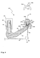
- a trailer hitch 11b has a coupling arm 14b with a plug-in end 80, which is arranged in a plug-in receptacle 82 of a vehicle fixed to the towing vehicle 12, for example, on the cross member 13 fixed bracket 81 can be inserted and locked by means not shown form-fitting contours on the plug-in receptacle 82.
- the clutch arm 14b is removable from the bracket 81 when not in use.
- a pivot bearing 17b is provided for a ball carrier 15b on which a ball head 16b is arranged.
- the ball carrier 15b forms a ball carrier rotary shaft 28b, which is rotatably received in a coupling arm bearing portion 29b of the coupling arm 14b.
- the ball head 16b is rotatable with respect to the vertical axis 25.
- the ball head 16b protrudes upward in front of the coupling arm 14b.
- the ball carrier 15b and the ball head 16b form a ball head piece 27b.
- a rotary encoder 42 and a rotation angle sensor 41 are received in the ball head 16b and at the free end of the coupling arm 14b recesses 83, 84 are provided, in which a rotary encoder 42 and a rotation angle sensor 41 are received.
- the rotary encoder 42 is disposed above the rotation angle sensor 41, so that the rotation angle sensor 41 is penetrated by the magnetic field of the rotary encoder 42.
- the rotation angle sensor 41 forms part of a sensor device 40b, which detects a rotation of the ball head 16b with respect to the coupling arm 14b about the vertical axis 25 and reports to an electrical system 86 of the towing vehicle 12.
- the sensor device 40b is connected via a line 85 leading to an appendix socket 87 for the power supply of the in FIG. 4 trailer, not shown, which in turn is connected to the electrical system 86.
- the socket 87 contains plug contacts for inserting a trailer-side plug.
- the pivot bearing 17b is associated with a braking device 68, for example, a piezoelectric braking device which brakes a rotation of the ball head 16b about the vertical axis 25 in response to a control signal.
- a braking device 68 for example, a piezoelectric braking device which brakes a rotation of the ball head 16b about the vertical axis 25 in response to a control signal.
- the sensor device 40b preferably contains the braking device 68 integrally.
- the sensor device 40b forms an integrated control device 44b for the brake device 68.
- the control device 44b increases or decreases the braking force of the brake device 68, for example, providing higher braking force for rapid rotation angle changes Trailer stabilization sets.
- the controller 44b sets a smaller braking force on the brake device 68.
- the two recesses 83, 84 are aligned.
- the lower recess 84 forms a channel from which the connection line 85 is led out.
- the two recesses 83, 84 extend substantially vertically.
- the line 85 exits below the ball head 16b from the coupling arm 14b down.
- a channel 90 extending along a neck portion 89 and leading in the direction of the towing vehicle 12 could be provided, so that the cable outlet for the conduit 85 is closer to the towing vehicle.
- the rotary encoder 42 is not arranged in the ball head 16b but in a trailer coupling 50b.
- a rotary encoder 42 ' e.g. a permanent magnet, arranged in a housing 53b of the trailer coupling 50b, which provides a ball seat 52b for coupling to the ball head 16b.
- a trailer hitch 11c according to FIGS. 5 and 6 is realized over the aforementioned trailer hitches improved rotary bearing concept. Otherwise, all embodiments and features illustrated in the trailer hitches 10a, 10b can also be applied to the trailer hitch 11c.
- a form-fitting contour 30 ' eg a groove or the like, for the positive connection with a in FIG. 5 not shown trailer coupling, for example, in the manner of the trailer hitches 50a, be provided.
- a sensor device 40c of the hitch 11c is configured similarly to the sensor device 40a, that is, it has, for example, a rotation angle sensor 41 which cooperates with a rotary encoder 42 to determine a rotational position of the ball head 16c with respect to the towing vehicle 12. Furthermore, the sensor device 40c has a communication interface 45 for coupling to the communication network 46 of the towing vehicle 12 shown schematically.
- a coupling arm 14 c can be fastened to the towing vehicle 12, for example, by means of a bolt connection.
- extending holes 210 are provided for the passage of fastening bolts.
- the coupling arm 14c is in the state mounted on the towing vehicle 12 substantially horizontally rearward in front of the towing vehicle 12.
- a coupling arm bearing portion 29c for rotatably supporting the ball head 16c is provided.
- the Kugelarm bearing portion 29c has a bearing receptacle 212, in which a spherical head 16c at its upper end festhaltender ball carrier 15c is rotatably received.
- the bearing receptacle 212 extends substantially vertically, so that the ball head 16 c is rotatable about a vertical axis 25.
- the bearing receiver 212 forms part of a pivot bearing 17c for the rotatable mounting of the ball head 16c.
- the ball arm bearing section 29c forms a type of hollow shaft 213, which rotatably receives the ball carrier 15c, which is configured as a ball carrier rotary shaft 28c at least in its lower section.
- the ball carrier 15c and the ball head 16c are firmly connected.
- an adhesive or welded connection could be provided for the fixed connection.
- a screw connection is provided at the trailer hitch 11c.
- a screw connection a screw 214 is screwed from an upper flat side of the ball head 16c into an upper end side of the ball carrier 15c.
- a screw 215 which extends in the longitudinal direction 216 of the ball carrier 15c.
- the bearing receiver 212 and the ball carrier rotary shaft 28c are elongated. This provides optimal support of the ball head piece 27c with respect to the coupling arm 14c, so that during operation of the hitch 11c occurring forces, in particular lateral forces, tensile forces and the like horizontal forces can be optimally absorbed by the pivot bearing 17c.
- a rotary shaft portion 217 of the ball carrier 15c projecting in front of the ball head 16c is approximately 1.5 to 2 times as long as a diameter of the ball head 16c.
- an axial stop 77 c is provided in an inner space 218.
- the axial stop 77 c is provided by an upper wall side 219 of the inner space 218.
- a lower axial stop 78c is provided at the end of the ball head piece 27c remote from the ball head 16c.
- the axial stop 78c is provided on a flange projection 220 of the ball carrier 15c.
- the flange projection 220 forms a kind of plate.
- the flange projection 220 is disposed at a free end of the ball support rotation shaft 28c remote from the ball head 16c. Consequently the coupling arm bearing portion 29c is received between the two axial stops 77c, 78c.
- a sliding bearing is provided between the axial stops 77c and / or 78c on the one hand and the coupling arm 14c on the other hand.
- axial roller bearings 221, 222 are provided.
- the front axial roller bearing 221 is supported on the one hand on the upper wall side 219 and on the other hand on an upper, free end 223 of the Kugelarm bearing portion 29c.
- the thrust roller bearing 221 is received in a bearing seat 224 of the inner space 218.
- the lower, provided substantially for the ball head 16c axial roller bearing 222 is received in a bearing receiving space 225 of the coupling arm 14c.
- the bearing receiving space 225 immediately adjoins the bearing receptacle 212 for the ball carrier rotary shaft 28c.
- a spring assembly 226 is provided between the axial stop 78c and the thrust roller bearing 222.
- the spring assembly 226 includes a plate spring 227 between the thrust roller bearing 222 and the flange projection 220.
- the plate spring 227 is penetrated by the ball carrier rotation shaft 28c.
- the spring arrangement 226 compensates, for example, for an axial clearance occurring during operation and / or due to wear of the trailer coupling 11c between the ball-arm bearing section 29c and the axial stops 77c, 78c.
- a radial rolling bearing 228 is provided for radially supporting the ball-headed piece 27c with respect to the ball-arm bearing portion 29c.
- the radial roller bearing 228 is arranged in a bearing receiving space 229 of the interior 218 of the ball head 16c and thus protected from environmental influences.
- the radial rolling bearing 228 is supported, on the one hand, on a peripheral wall 230 of the upper, free end 223 of the ball-arm bearing section 29c, which projects into the inner space 218, and on the other hand, an inner peripheral wall 231 of the bearing receiving space 229 or of the inner space 218 ,
- the radial rolling bearing 228 is completely received in the inner space 218 and thus already well protected against environmental influences.
- seals 232, 233 are provided as additional sealing measures.
- the seals 232, 233 are suitably O-rings.
- the seal 232 is disposed between the ball head 16c and the peripheral wall 230 for sealing the inner space 218 of the ball head 16c receiving the rolling bearings 221, 228.
- the free, accommodated in the inner space 218 free end 223 has a smaller diameter than a lying outside of the inner space 218 portion of the Kugelarm bearing portion 29c, thereby creating a seal seat for the seal 232 is provided.
- the seal 233 is disposed between the flange projection 220 and a lower end face of the ball arm support portion 29c in the drawing, for example, in an annular groove 234 on this end face.
- the sensor device 40c comprises a protective housing 70c in which the rotational angle sensor 41 is accommodated, for example a magnetoresistive sensor, a Hall sensor or the like.
- the rotational angle sensor 41 is located directly below the ball head piece 27c, in particular directly below the free end of the ball carrier rotary shaft 28c.
- a receptacle 235 is provided for the rotary encoder 42, for example, a permanent magnet.
- the rotation angle sensor 41 may also be an optical sensor which scans optical markings on the ball head piece 27c, for example line markings, and generates a rotation angle signal 37 therefrom.
- the ball support rotation shaft 28c forms a transmission member 241 for transmitting a rotational position of the ball head 16c to the rotation angle sensor 41.
- the rotation angle sensor 41 is disposed on the clutch arm 14c at a distance from the ball head 16c.
- the communication interface 45 is designed for coupling to a parking assistance system 260 of the towing vehicle 12 and / or the driving stabilization device 47 of the towing vehicle 12.
- a parking assistance system 260 which controls, for example front, steerable wheels 49 and also also a drive motor and brakes of the towing vehicle 12
- an automatic or semi-automatic parking of the combination of towing vehicle 12 and trailer 51 is possible.
- the hitch 11c may be suitably configured with at least one braking device, e.g. with a braking device 69, for braking a rotational movement of the ball head 16c relative to the coupling arm 14c.
- the braking device 69 is arranged, for example, on the pivot bearing 17c.
- the braking device 69 operates according to a magnetic principle, a friction principle or the like.
- a braking force of the braking device 69 can be controlled by a control device 44c which, for example in the manner of the above-described control device 44a, 44c, in particular interactively with devices of the towing vehicle 12, controls the braking device 69 to set its braking force.
- the braking device 69 is configured to completely decelerate in the sense of blocking the ball head 16c.
- a blocking device 236 is provided with which a rotational movement of the ball head 16c with respect to the coupling arm 14c is completely blocked.
- the blocking device 236 comprises a blocking part 237 which is displaceably mounted on the ball arm bearing section 29c and which engages in a blocking receptacle 238 on the ball head piece 27c, for example its ball bearing rotary shaft 28c.
- the protective housing 70c is fastened to the coupling arm 14c, for example, by means of a screw 239.
- a protective housing for a sensor device and / or a control device of a trailer coupling according to the invention can also form an integral part of a coupling arm.
- the protective housing 70c has a cable outlet 240 for passing connecting lines to the communication network 46 of the towing vehicle 12, for example at a bottom of the protective housing.
- a wireless connection between the sensor device and / or control device for the braking device on the one hand and communication network of a towing vehicle on the other hand is wireless.
- a wireless and wired connection between a towing device according to the invention and the towing vehicle is advantageous, wherein, for example, control information and message information are transmitted wirelessly while a power flow is wired.
- an electrical buffer store for example a buffer capacitor, accumulator or the like is provided on the side of the sensor device and / or the control device for the braking device.
- the sensor device in particular its protective housing, is not arranged below a lowest point of the respective coupling arm or at least not projecting in front of the lowest coupling arm point.
- the coupling arm 14c for example, a curvature 242, so that the protective housing 70c is disposed in a region of the coupling arm 14c curved away from the ground and at least not substantially before a deepest portion 243 of the coupling arm 14c projects downward.
- the deepest region 243 is in the vicinity of the towing vehicle 12, while the curved away, upper region, on which the sensor device 40c is arranged, in the region of the free end 211 of the coupling arm 14c.
Abstract
Description
Die Erfindung betrifft eine Anhängekupplung für ein Zugfahrzeug, insbesondere ein Personen-Kraftfahrzeug, zum Anhängen eines Anhängers an das Zugfahrzeug, mit einer Kupplungskugel, die an einem freien Ende eines Kugelträgers angeordnet ist und auf die eine Kupplungsaufnahme einer Anhänger-Kupplung des Anhängers aufsetzbar ist, und mit einem Drehlager zur drehbaren Lagerung des Kugelkopfs bezüglich des Zugfahrzeugs.The invention relates to a towing hitch for a towing vehicle, in particular a passenger motor vehicle, for attaching a trailer to the towing vehicle, with a coupling ball, which is arranged at a free end of a ball carrier and on which a coupling receptacle of a trailer coupling of the trailer can be placed, and with a pivot bearing for rotatably supporting the ball head with respect to the towing vehicle.
Eine derartige Anhängekupplung ist beispielsweise aus der
Das Drehlager, das beispielsweise ein Gleitlager oder Wälzlager ist, ist in einem Innenraum des Kugelkopfs angeordnet und befindet sich zwischen dem Kugelkopf und dem oberen Ende des Kupplungsschaftes, der somit die Funktion eines Kugelträgers hat. Zudem ist im Innenraum des Kugelkopfes noch eine Sensoreinrichtung zur Drehwinkelerfassung des Kugelkopfes bezüglich des Kraftfahrzeuges vorhanden.The pivot bearing, which is for example a plain bearing or rolling bearing is arranged in an interior of the ball head and is located between the ball head and the upper end of the coupling shaft, which thus has the function of a ball carrier. In addition, a sensor device for detecting the rotation angle of the ball head with respect to the motor vehicle is still present in the interior of the ball head.
Das bekannte Lagerkonzept hat unter anderem den Nachteil, dass auf den Kugelkopf bezüglich der Fahrzeughochachse wirkende Stützkräfte oder auch Zugkräfte des Anhängers, beispielsweise beim Überfahren einer Kuppe, direkt auf das Wälzlager im Innenraum des Kugelkopfs wirken.The known bearing concept has, inter alia, the disadvantage that on the ball head with respect to the vehicle vertical axis acting supporting forces or tensile forces of the trailer, for example when driving over a dome, act directly on the rolling bearing in the interior of the ball head.
Es ist daher die Aufgabe der vorliegenden Erfindung, ein verbessertes Lagerkonzept für eine Anhängekupplung der eingangs genannten Art zu stellen.It is therefore the object of the present invention to provide an improved bearing concept for a trailer coupling of the type mentioned.
Zur Lösung der Aufgabe ist bei einer Anhängekupplung der eingangs genannten Art vorgesehen, dass die Kupplungskugel und der Kugelträger fest verbunden oder einstückig sind und ein Kugelkopfstück bilden, dass der Kugelträger an einem mit dem Zugfahrzeug fest verbindbaren oder verbundenen Kupplungsarm anhand des Drehlagers um eine Drehachse drehbar gelagert ist, wobei der Kugelträger vor den Kugelkopf vorsteht und eine Kugelträgerdrehwelle zur Drehlagerung des Kugelkopfs an einem Kupplungsarm-Lagerabschnitt des Kupplungsarms bildet oder aufweist.To solve the problem is provided in a trailer hitch of the type mentioned above, that the coupling ball and the ball carrier are firmly connected or integral and form a ball head piece that the ball carrier on a firmly connected to the towing vehicle or connected coupling arm based on the pivot bearing about an axis of rotation is mounted, wherein the ball carrier projects in front of the ball head and forms a ball support rotary shaft for pivotal mounting of the ball head on a coupling arm bearing portion of the coupling arm or has.
Die Kupplungskugel ist mit dem Kugelträger fest verbunden oder einstückig. Der Kugelträger wiederum ist mittels des Drehlagers an einem mit dem Zugfahrzeug fest verbindbaren oder verbundenen Kupplungsarm um eine Hochachse des Zugfahrzeugs drehbar gelagert. Diese Ausführungsform ließe sich im Prinzip auch ohne die oben genannte Bremseinrichtung realisieren. Im Unterschied zu der Drehlagerung gemäß
Der Kugelträger und der Kugelkopf sind beispielsweise mittels einer Schweißverbindung, einer Klebeverbindung oder einer Schraubverbindung miteinander verbunden, wobei Kombinationen ohne weiteres möglich sind. Wenn der Kugelträger und der Kugelkopf zunächst voneinander getrennte Bauteile sind, ist beispielsweise eine leichtere Fertigung der beiden Bauteile und/oder eine effizientere Montagetechnik möglich.The ball carrier and the ball head are, for example, by means of a welded joint, an adhesive bond or a Screw connected together, with combinations are readily possible. If the ball carrier and the ball head are initially separate components, for example, a lighter production of the two components and / or a more efficient assembly technique is possible.
Die Drehlagerung erfolgt bei der erfindungsgemäßen Anhängekupplung vorzugsweise um eine Hochachse. Die Drehachse könnte z.B. aber auch schräg zur Hochachse stehen.The pivot bearing takes place in the trailer coupling according to the invention preferably around a vertical axis. The axis of rotation could e.g. but also obliquely to the vertical axis.
Der Kupplungsarm-Lagerabschnitt weist beispielsweise eine Lageraufnahme oder einen Lagervorsprung für die Kugelträgerwelle auf oder bildet einen Lagervorsprung oder eine Lageraufnahme.The coupling arm bearing section has, for example, a bearing receptacle or a bearing projection for the ball carrier shaft or forms a bearing projection or a bearing receptacle.
Der Kupplungsarm-Lagerabschnitt ist zweckmäßigerweise als eine die Kugelträgerwelle aufnehmende Hohlwelle ausgestaltet. Mithin hat der Kupplungsarm also einen Hohlwellenabschnitt, in dem die Kugelträgerdrehwelle aufgenommen ist. Eine alternative Ausführungsform kann vorsehen, dass die Kugelträgerdrehwelle als eine Hohlwelle ausgestaltet ist, die auf einen entsprechenden Lagervorsprung des Kupplungsarm-Lagerabschnitts aufgesetzt ist.The coupling arm bearing portion is expediently configured as a hollow shaft receiving the ball carrier shaft. Thus, the coupling arm thus has a hollow shaft portion in which the ball carrier rotary shaft is received. An alternative embodiment may provide that the ball carrier rotary shaft is designed as a hollow shaft, which is placed on a corresponding bearing projection of the coupling arm bearing portion.
Es versteht sich, dass der Kupplungsarm-Lagerabschnitt und die Kugelträgerdrehwelle unmittelbar mit z.B. einer Gleitlagerung aneinander gelagert sein können. Alternativ ist es auch möglich, dass zwischen den beiden Bauteilen ein Wälzlager, beispielsweise ein Nadellager, Kugellager oder dergleichen, angeordnet ist.It will be understood that the coupling arm bearing portion and the ball bearing pivot shaft are directly connected to e.g. a sliding bearing can be stored together. Alternatively, it is also possible that a rolling bearing, for example a needle bearing, ball bearings or the like, is arranged between the two components.
Eine besonders bevorzugte Ausführungsform sieht vor, dass die Kugelträgerdrehwelle eine langgestreckte Form aufweist, so dass eine optimale Einleitung von quer zur Drehachse wirkenden Kräften auf den Kupplungsarm möglich ist. Die Länge eines vor den Kugelkopf vorstehenden Drehwellenabschnitts der Kugelträgerdrehwelle entspricht zweckmäßigerweise zumindest einem Durchmesser des Kugelkopfs, ist aber vorzugsweise größer, beispielsweise 1,5 bis 2-fach größer als der Durchmesser des Kugelkopfs oder gar noch größer. Somit hat das Kugelkopfstück ein verhältnismäßig langes Axiallager bezüglich des Kupplungsarmes.A particularly preferred embodiment provides that the ball carrier rotary shaft has an elongated shape, so that an optimal introduction of forces acting transversely to the axis of rotation on the coupling arm is possible. The length of a front of the ball protruding rotary shaft portion of the ball carrier rotation shaft suitably corresponds to at least one Diameter of the ball head, but is preferably larger, for example, 1.5 to 2 times larger than the diameter of the ball head or even larger. Thus, the ball head has a relatively long thrust bearing with respect to the coupling arm.
Entlang der Drehachse des Drehlagers können Axialkräfte auftreten, beispielsweise durch eine auf der Kupplungskugel auflastende Anhängelast. Darüber hinaus können aber auch Zugkräfte auftreten, beispielsweise beim Überfahren von Kuppen oder Durchfahren von Senken oder dergleichen. Daher weist die Anhängekupplung zweckmäßigerweise mindestens einen gegen ein Verschieben entlang der Drehachse wirksamen Axialanschlag auf, beispielsweise am Kugelkopfstück, insbesondere am Kugelträger. Es versteht sich, dass auch der Kupplungskopf einen solchen Axialanschlag aufweisen kann.Along the axis of rotation of the pivot bearing axial forces can occur, for example, by a load on the coupling ball trailer load. In addition, however, tensile forces can also occur, for example, when driving over hills or passing through depressions or the like. Therefore, the trailer coupling expediently has at least one axial stop acting against displacement along the axis of rotation, for example on the ball head piece, in particular on the ball carrier. It is understood that also the coupling head can have such an axial stop.
Der mindestens eine Axialanschlag ist vorzugsweise als ein Bestandteil eines Axiallagers ausgestaltet oder weist ein Axiallager auf. Das Axiallager ist z.B. ein Gleitlager oder Wälzlager.The at least one axial stop is preferably designed as a component of a thrust bearing or has a thrust bearing. The thrust bearing is e.g. a plain bearing or rolling bearing.
Der mindestens eine Axialanschlag ist vorzugsweise an einem Flanschvorsprung des Kugelträgers vorgesehen. Es versteht sich, dass als Axialanschläge auch beispielsweise eine Ringnut oder ein Ringvorsprung an der Kugelträgerdrehwelle vorgesehen sein können.The at least one axial stop is preferably provided on a flange projection of the ball carrier. It is understood that may be provided as an axial stops, for example, an annular groove or an annular projection on the ball carrier rotary shaft.
Der Kupplungsarm-Lagerabschnitt steht zweckmäßigerweise in einen Innenraum des Kugelkopfs vor. Somit sind auch dort, das heißt im Innenraum des Kugelkopfs, später noch beschriebene Anordnungen von Axiallagern und/oder Radiallagern ohne weiteres möglich.The coupling arm bearing portion is expediently in an interior of the ball head. Thus, even there, that is in the interior of the ball head, later described arrangements of thrust bearings and / or radial bearings readily possible.
Vorteilhaft ist der Kupplungsarm-Lagerabschnitt zwischen Axialanschlägen des Kugelkopfstücks angeordnet. Von diesem kann einer beispielsweise durch den vorgenannten Flanschvorsprung, der andere durch das Kugelkopfstück, insbesondere eine Innenwandung desselben gebildet sein.Advantageously, the coupling arm bearing portion between axial stops of the ball head piece is arranged. From this one can be formed, for example, by the aforementioned flange projection, the other by the ball head piece, in particular an inner wall of the same.
Zweckmäßigerweise ist dem mindestens einen Axialanschlag ein um die Drehachse drehbares Axial-Wälzlager zur Aufnahme von entlang der Drehachse auf den Kugelkopf wirkenden Kräften zugeordnet. Es versteht sich, dass bei mehreren Axialanschlägen vorzugsweise allen Axialanschlägen, ein solches Axial-Wälzlager zugeordnet ist. Gegenüber eine Gleitlagerung wird dadurch die Drehbarkeit des Kugelkopfstücks bezüglich des Kupplungsarms verbessert. Das Axial-Wälzlager ist zweckmäßigerweise zwischen dem Axialanschlag und dem Kupplungsarm-Lagerabschnitt angeordnet. Wenn man das Axial-Wälzlager als einen Bestandteil des Kugelkopfstücks bezeichnen wollte, würde es beispielsweise den Axialanschlag bilden. Das Axial-Wälzlager nimmt zweckmäßigerweise Zugkräfte oder Druckkräfte auf, je nach dem welchem Axialanschlag es zugeordnet ist. Beispielsweise nimmt das Axial-Wälzlager eine auf dem Kugelkopf auflastende Stützlast auf.Conveniently, the at least one axial stop is associated with a rotatable about the axis of rotation thrust roller bearing for receiving along the axis of rotation acting on the ball head forces. It is understood that in the case of several axial stops, preferably all axial stops are associated with such an axial rolling bearing. Compared to a sliding bearing thereby the rotatability of the ball head piece is improved with respect to the coupling arm. The axial roller bearing is expediently arranged between the axial stop and the coupling arm bearing section. If one wanted to designate the thrust bearing as a part of the ball head piece, it would form, for example, the axial stop. The axial roller bearing expediently absorbs tensile forces or compressive forces, depending on which axial stop it is associated with. For example, the axial rolling bearing absorbs a load on the ball head load.
Vorzugsweise ist auch ein Radial-Wälzlager zwischen dem Kugelkopf und dem Kupplungsarm-Lagerabschnitt vorgesehen.Preferably, a radial rolling bearing is provided between the ball head and the coupling arm bearing portion.
Es versteht sich, dass alternativ zu den obengenannten Radial-und/oder Axial-Wälzlagern auch eine Gleitlagerung möglich ist.It is understood that as an alternative to the above-mentioned radial and / or axial rolling bearings and a sliding bearing is possible.
Bei dem Begriff "Wälzlager" sind selbstverständlich alle Typen von Wälzlagern umfasst, beispielsweise Kugellager, Rollenlager, Tonnenlager, Nadellager oder dergleichen.The term "roller bearing" of course, all types of bearings include, for example, ball bearings, roller bearings, roller bearings, needle roller bearings or the like.
Wie oben bereits angedeutet, ist in einem Innenraum des Kugelkopfs zweckmäßigerweise mindestens ein Wälzlager, beispielsweise ein Radial-Wälzlager und/oder ein Axial-Wälzlager, angeordnet.As already indicated above, in an interior of the ball head expediently at least one rolling bearing, for example a radial roller bearing and / or an axial roller bearing arranged.
Weiterhin ist es vorteilhaft, wenn mindestens eine Dichtung zwischen dem Kupplungsarm-Lagerabschnitt und einem Bestandteil des Kugelkopfstücks, beispielsweise der Kugelträgerdrehwelle oder dem Kugelkopf, vorgesehen ist. Insgesamt ist es vorteilhaft, wenn eine Dichtungsanordnung sämtliche beweglichen Bestandteile der erfindungsgemäßen Anhängekupplung gegen Umwelteinflüsse abdichtet.Furthermore, it is advantageous if at least one seal between the coupling arm bearing portion and a part of the ball head piece, for example, the ball support rotary shaft or the ball head, is provided. Overall, it is advantageous if a sealing arrangement seals all movable components of the trailer coupling according to the invention against environmental influences.
Die Anhängekupplung hat vorteilhaft mindestens eine gegen ein Axialspiel und/oder ein Radialspiel des Kugelkopfstücks bezüglich des Kupplungsarm-Lagerabschnitts des Kupplungsarms wirkende Federanordnung. Die Federanordnung kann beispielsweise eine Tellerfeder oder mehrere Tellerfedern umfassen. Das erfindungsgemäße Lagerkonzept kann z.B. ein gewisses Spiel einerseits dem Kupplungsarm-Lagerabschnitt und andererseits dem Kugelkopfstück vorsehen, z.B. in Richtung der Drehachse. Ferner kann ein solches Spiel beim Fahrbetrieb, insbesondere durch Abnutzung, entstehen. Dem Spiel wirkt die Federanordnung entgegen. Beispielsweise ist die Federanordnung zwischen dem mindestens einen Axialanschlag und dem Kupplungsarm-Lagerabschnitt angeordnet. Es ist auch möglich, die Federanordnung zwischen beispielsweise dem oben genannten Axial-Lager und dem Axialanschlag oder dem Kupplungsarm-Lagerabschnitt anzuordnen. Selbstverständlich können auch mehrere Federanordnungen vorgesehen sein.The trailer coupling advantageously has at least one spring arrangement acting against axial play and / or radial play of the ball head piece with respect to the coupling arm bearing section of the coupling arm. The spring arrangement may comprise, for example, a plate spring or a plurality of disc springs. The storage concept according to the invention can e.g. a certain play on the one hand the coupling arm bearing portion and on the other hand provide the ball head piece, e.g. in the direction of the axis of rotation. Furthermore, such a game during driving, in particular by wear, arise. The game counteracts the spring arrangement. For example, the spring arrangement is arranged between the at least one axial stop and the coupling arm bearing section. It is also possible to arrange the spring arrangement between, for example, the abovementioned axial bearing and the axial stop or the coupling arm bearing section. Of course, several spring arrangements can be provided.
Vorteilhaft weist die Anhängekupplung eine Bremseinrichtung zum Bremsen einer Drehung des Kugelkopfs bezüglich des Zugfahrzeugs auf. Der Kugelkopf kann zwar drehen, die Bremseinrichtung bremst jedoch die Drehung. In manchen Fahrsituationen blockiert die Bremseinrichtung vorzugsweise sogar. Dadurch ist es möglich, das Gespann auch bei höheren Geschwindigkeiten zu stabilisieren. Das Drehlager ermöglicht zweckmäßigerweise einen Drehfreiheitsgrad bezüglich einer Hochachse, wobei auch ein Drehfreiheitsgrad bezüglich einer horizontal verlaufenden Achse vorteilhaft mittels der Bremseinrichtung bremsbar ist.Advantageously, the hitch on a braking device for braking a rotation of the ball head with respect to the towing vehicle. Although the ball head can rotate, the braking device brakes the rotation. In some driving situations, the braking device preferably even blocks. This makes it possible to do that Team to stabilize even at higher speeds. The pivot bearing expediently allows a rotational degree of freedom with respect to a vertical axis, wherein a rotational degree of freedom with respect to a horizontally extending axis can advantageously also be braked by means of the braking device.
Ein an sich bei jeder Anhängekupplung mit einem drehbaren Kugelkopf sinnvolle Maßnahme, die auch bei der erfindungsgemäßen Anhängekupplung vorteilhaft ist, wenn die jeweilige Anhängekupplung eine Blockiereinrichtung zum Blockieren einer Drehung des Kugelkopfs bezüglich des Zugfahrzeugs aufweist. Dies ist insbesondere dann vorteilhaft, wenn die Anhängekupplung beispielsweise zum Tragen eines Heckträgers, insbesondere eines Fahrradträgers, verwendet werden soll. Die Blockierung kann beispielsweise durch ein entsprechendes Riegelelement realisiert sein. Es ist aber auch möglich, dass die oben erläuterte Bremseinrichtung zum Blockieren des Kugelkopfs bezüglich des Kupplungsarmes ausgestaltet ist, das heißt zu einem vollständigen, keine Bewegung des Kupplungsarms zulassenden Bremsung.An in itself in each trailer hitch with a rotatable ball head meaningful measure, which is also advantageous in the trailer coupling according to the invention, when the respective hitch has a blocking device for blocking a rotation of the ball head with respect to the towing vehicle. This is particularly advantageous if the hitch is to be used for example for carrying a rear carrier, in particular a bicycle carrier. The blocking can be realized for example by a corresponding locking element. But it is also possible that the above-described braking device is designed to block the ball head with respect to the coupling arm, that is to a complete, no movement of the coupling arm permitting braking.
Eine weitere vorteilhafte Ausgestaltung der Erfindung sieht vor, dass die Anhängekupplung eine Sensoreinrichtung zur Erfassung einer Drehwinkellage des Anhängers bezüglich des Zugfahrzeugs aufweist, wobei die Sensoreinrichtung einen fahrzeugfest angeordneten Drehwinkelsensor, vorzugsweise einen magnetischen Sensor und/oder optischen Sensor, zur Zusammenwirkung mit einem Drehwinkelgeber, z.B. einem Permanentmagneten, einer optischen Markierung oder dergleichen, umfasst, der bezüglich des Kugelkopf drehfest ist. Es ist auch möglich, dass der Drehwinkelgeber fahrzeugfest ist und der Drehwinkelsensor eine Drehung des Kugelkopfs mitmacht. Die Sensoreinrichtung kann selbstverständlich auch mehrere Drehwinkelsensoren umfassen.A further advantageous embodiment of the invention provides that the trailer coupling has a sensor device for detecting a rotational angle position of the trailer with respect to the towing vehicle, wherein the sensor device is a vehicle fixed rotational angle sensor, preferably a magnetic sensor and / or optical sensor, for cooperation with a rotary encoder, eg a permanent magnet, an optical marking or the like, which is rotationally fixed relative to the ball head. It is also possible that the rotary encoder is fixed to the vehicle and the rotation angle sensor participates in a rotation of the ball head. Of course, the sensor device may also comprise a plurality of rotation angle sensors.
Der Drehwinkelgeber ist zweckmäßigerweise an dem Kugelträger oder dem Kugelkopf angeordnet. Es versteht sich, dass auch mehrere Drehwinkelgeber vorgesehen sein können. Der oder die Drehwinkelgeber können auch am Anhänger, vorzugsweise an der Anhänger-Kupplung angeordnet sein. Beispielsweise ist es möglich, einen oder mehrere Permanentmagnete an einer Kupplungspfanne der Anhänger-Kupplung anzubringen.The rotary encoder is expediently arranged on the ball carrier or the ball head. It is understood that several rotary encoder can be provided. The one or more rotary encoder can also be arranged on the trailer, preferably on the trailer coupling. For example, it is possible to attach one or more permanent magnets to a coupling socket of the trailer coupling.
Der Drehwinkelsensor umfasst zweckmäßigerweise mindestens einen Magnetsensor, während der Drehwinkelgeber mindestens einen Permanentmagneten umfasst. Vorzugsweise ist der mindestens eine Drehwinkelsensor ein magnetoresistiver Sensor, z.B. ein AMR oder GMR Sensor. Bevorzugt ist ein winkelabhängiger Sensor. Es können auch mehrere Sensoren vorgesehen sein, insbesondere um einen Drehwinkel an verschiedenen Stellen zu erfassen.The angle of rotation sensor expediently comprises at least one magnetic sensor, while the rotary encoder comprises at least one permanent magnet. Preferably, the at least one rotation angle sensor is a magnetoresistive sensor, e.g. an AMR or GMR sensor. Preferred is an angle-dependent sensor. It can also be provided several sensors, in particular to detect a rotation angle at different locations.
Der Drehwinkelsensor ist vorzugsweise an dem den Kugelkopf haltenden Kupplungsarm angeordnet. Der Kupplungsarm ist fahrzeugfest, während der Kugelkopf relativ zu diesem Drehlager drehbar ist.The angle of rotation sensor is preferably arranged on the coupling head holding the ball. The coupling arm is fixed to the vehicle, while the ball head is rotatable relative to this pivot bearing.
Der Drehwinkelgeber ist vorzugsweise an dem Kugelträger oberhalb des Drehwinkelsensors angeordnet. Somit befindet sich der Drehwinkelsensor unterhalb des Kugelträgers. Der Kugelträger, z.B. die Kugelträgerdrehwelle, bildet vorteilhaft ein Übertragungsglied zur Übertragung einer Drehposition des Kugelkopfs Ein Magnetfeld des Drehwinkelgebers verläuft zweckmäßigerweise quer zur Hochachse, vorteilhaft horizontal, im Bereich des mindestens einen Drehwinkelsensors.The rotary encoder is preferably arranged on the ball carrier above the rotation angle sensor. Thus, the rotation angle sensor is located below the ball carrier. The ball carrier, e.g. A magnetic field of the rotary encoder expediently runs transversely to the vertical axis, advantageously horizontally, in the region of the at least one angle of rotation sensor.
Vorteilhaft ist es, den Drehwinkelgeber an oder in einem vorzugsweise nicht magnetischen Bereich des Kugelträgers oder des Kupplungskugel anzuordnen, z.B. in Aluminium oder Kunststoff. Selbstverständlich ist es auch bei dem Drehwinkelsensor vorteilhaft, diesen in einem nicht magnetischen Bereich anzuordnen. Es hat sich aber in der Praxis gezeigt, dass durch entsprechende Kalibrierung auch eine Unterbringung in magnetischen Material möglich ist.It is advantageous to arrange the rotary encoder on or in a preferably non-magnetic region of the ball carrier or the coupling ball, for example in aluminum or plastic. Of course, it is also in the rotation angle sensor advantageous to arrange this in a non-magnetic area. However, it has been found in practice that by appropriate calibration and accommodation in magnetic material is possible.
Der Drehwinkelgeber und/oder der Drehwinkelsensor sind vorzugsweise gegen Umwelteinflüsse geschützt. In der Praxis ist beispielsweise ein Gehäuse, ein Eingießen der betreffenden Bauteile oder dergleichen vorteilhaft. Es können auch Schutzaufnahmen für den Drehwinkelgeber oder den Drehwinkelsensor beispielsweise am Kugelträger, Kupplungsarm oder Kugelkopf vorgesehen sein, in denen das jeweilige Bauteil geschützt unterbringbar ist. Das vorgenannte Gehäuse hat z.B. zwei zueinander relativ drehbewegliche Gehäuseteile, von denen eines fahrzeugfest und das andere drehfest mit dem Kugelkopf oder dem Kugelträger verbunden ist. Zwischen den beiden Gehäuseteilen ist zweckmäßigerweise eine Dichtung, vorteilhaft z.B. eine Labyrinthdichtung vorgesehen.The rotary encoder and / or the rotation angle sensor are preferably protected against environmental influences. In practice, for example, a housing, a pouring of the relevant components or the like are advantageous. It can also be provided protective receptacles for the rotary encoder or the rotation angle sensor, for example on the ball carrier, coupling arm or ball head, in which the respective component is protected housed. The aforementioned housing has e.g. two mutually relatively rotatable housing parts, one of which is fixed to the vehicle and the other non-rotatably connected to the ball head or the ball carrier. Between the two housing parts is expediently a seal, advantageously e.g. provided a labyrinth seal.
Die Sensoreinrichtung hat vorzugsweise eine Kommunikationsschnittstelle für ein Kommunikationsnetz des Zugfahrzeugs, beispielsweise ein Bus-Schnittstelle. Somit kann die Sensoreinrichtung auf dem Kommunikationsnetz, beispielsweise einem CAN-Bus, einem FlexRay-Bus oder dergleichen, Drehwinkelinformationen versenden, die sie anhand des Drehwinkelgebers erfasst.The sensor device preferably has a communication interface for a communication network of the towing vehicle, for example a bus interface. Thus, the sensor device on the communication network, for example, a CAN bus, a FlexRay bus or the like, send rotational angle information, which detects them on the basis of the rotary encoder.
Ein weiterer, an sich bei jeder Sensoreinrichtung für eine Anhängekupplung, die einen Drehwinkel erfassen kann, sinnvolle Maßnahme ist, dass die Sensoreinrichtung zur Ermittlung einer Basiswinkellage des Kugelkopfs oder der Anhänger-Kupplung relativ zum Kupplungsarm, d.h. relativ zum Zugfahrzeug, Fahrinformationen über einen Fahrzustand des Zugfahrzeugs auf dem Kommunikationsnetz empfängt und auswertet. Dieser Fahrzustand ist zweckmäßigerweise eine Information über eine Fahrtrichtung. Beispielsweise enthält die Fahrinformation über den Fahrzustand Drehzahlinformationen von Drehzahlgebern des Zugfahrzeugs, so dass die Sensoreinrichtung anhand dieser Drehzahlinformationen eine Geradeausfahrt, eine Kurvenfahrt, eine Vorwärtsfahrt oder eine Rückwärtsfahrt ermitteln kann.Another, at each sensor device for a towing hitch, which can detect a rotation angle, meaningful measure is that the sensor device for determining a base angular position of the ball head or the trailer coupling relative to the coupling arm, ie relative to the towing vehicle, driving information on a driving condition of Towing vehicle on the communication network receives and evaluates. This driving condition is expediently information about a direction of travel. For example, the driving information about the driving state contains rotational speed information of speed sensors of the towing vehicle, so that the sensor device can determine a straight ahead, a cornering, a forward drive or a reverse drive on the basis of this speed information.
So ist es beispielsweise möglich, dass die Sensoreinrichtung bei einer Geradeaus-Vorwärtsfahrt ein jeweiliges Drehwinkelsignal des Drehwinkelsensors als eine Basiswinkelinformation ermittelt.Thus, for example, it is possible for the sensor device to determine a respective rotational angle signal of the rotational angle sensor as a base angle information in the case of a straightforward forward drive.
Die erfindungsgemäße Anhängekupplung ist vorzugsweise zur Ermittlung einer Geradeaus-Stellung des Kupplungskopfs bzw. des daran angekoppelten Anhängers bezüglich des Zugfahrzeugs ausgestaltet.The trailer coupling according to the invention is preferably designed to determine a straight-ahead position of the coupling head or of the trailer coupled thereto with respect to the towing vehicle.
Es versteht sich, dass die Fahrinformationen auch sozusagen aufbereitete Fahrinformationen sein können, beispielsweise von einer elektronischen Fahrstabilisierung, von einem Antiblockiersystem oder dergleichen, aufbereitete Fahrinformationen. Auch Fahrinformationen eines an das Kommunikationsnetz angeschlossenen Drehwinkelsensors können von der Sensoreinrichtung ausgewertet werden.It is understood that the driving information can also be so-called processed driving information, for example, from an electronic driving stabilization, an antilock braking system or the like, prepared driving information. Driving information of a rotational angle sensor connected to the communication network can also be evaluated by the sensor device.
Die Sensoreinrichtung ist zweckmäßigerweise zu einer Kommunikation mit einer elektronischen Fahrstabilisierungseinrichtung des Zugfahrzeugs ausgestaltet. Dazu hat die Sensoreinrichtung beispielsweise einen entsprechenden Kommunikationscontroller. Somit kann die Sensoreinrichtung beispielsweise Fahrinformationen über den Fahrzustand des Zugsfahrzeugs von dieser Fahrstabilisierungseinrichtung erhalten und umgekehrt die Drehwinkelinformationen an die Fahrstabilisierungseinrichtung senden.The sensor device is expediently designed for communication with an electronic driving stabilization device of the towing vehicle. For this purpose, the sensor device has, for example, a corresponding communication controller. Thus, the sensor device can, for example, obtain driving information about the driving state of the towing vehicle from this driving stabilization device and, conversely, send the rotational angle information to the driving stabilization device.
Auch eine Kommunikation mit einer Einparkhilfeeinrichtung oder einem Einparksystem zum Einparken des Zugfahrzeugs mit oder ohne angehängtem Anhänger ist vorteilhaft. So kann die erfindungsgemäße Anhängekupplung bei dieser Ausgestaltung der Erfindung über ihre Kommunikationsschnittstelle einem derartigen Einparkhilfesystem Winkelinformationen über den Kupplungskopf und somit den daran angehängten Anhänger übermitteln, so dass das Einparkhilfesystem das Zugfahrzeug mit angehängtem Anhänger in eine Parklücke oder Parkbucht einparken kann. Es versteht sich, dass hier ein halbautomatisches oder vollautomatisches Einparken ohne weiteres möglich ist.Also, communication with a parking aid device or a parking system for parking the towing vehicle with or without trailer attached is advantageous. Thus, the hitch invention in this embodiment of the invention via its communication interface such a parking aid system angle information on the coupling head and thus the attached trailer, so that the parking aid system can park the towing vehicle with attached trailer in a parking space or parking bay. It is understood that a semi-automatic or fully automatic parking is readily possible here.
Bei der Bremseinrichtung sind verschiedenartige mechanische Ausgestaltungen möglich. Beispielsweise enthält die Bremseinrichtung eine Reibbremse, eine piezo-elektrische Bremseinrichtung oder dergleichen.In the braking device various mechanical configurations are possible. For example, the braking device includes a friction brake, a piezoelectric braking device or the like.
Vorzugsweise wirkt die Bremseinrichtung auf den Kugelkopf oder den Kugelträger. Es ist aber auch möglich, dass die Bremseinrichtung auf das Drehlager wirkt, beispielsweise einen Druck auf das Drehlager auswirkt, so dass das Drehlager leichter oder schwerer dreht.Preferably, the braking device acts on the ball head or the ball carrier. But it is also possible that the braking device acts on the pivot bearing, for example, a pressure on the pivot bearing affects, so that the pivot bearing rotates easier or harder.
Eine Bremskraft der Bremseinrichtung ist vorzugsweise einstellbar. Dazu hat die Bremseinrichtung vorzugsweise einen Stelleingang. Beispielsweise hat die Bremseinrichtung einen elektrischen Stellantrieb, z.B. einen elektromagnetischen Antrieb, zum Einstellen der Bremskraft. Vorzugsweise ist eine Steuereinrichtung zu einer Veränderung der Bremskraft der Bremseinrichtung in Abhängigkeit von einem oder mehreren der nachfolgenden Parameter vorgesehen:
- Fahrtrichtung
- Fahrgeschwindigkeit
- Drehwinkelgeschwindigkeit eines Drehwinkels des Anhängers relativ zu dem Zugfahrzeug.
- direction of travel
- driving speed
- Rotational angular velocity of a rotation angle of the trailer relative to the towing vehicle.
Somit kann die Steuereinrichtung beispielsweise bei langsamer Fahrt oder Rückwärtsfahrt eine kleine Bremskraft einstellen, was die Beweglichkeit des Gespanns verbessert, während bei schneller Fahrt, insbesondere schneller Vorwärtsfahrt, eine hohe Bremskraft zweckmäßig ist. Selbstverständlich ist es möglich, dass die Steuereinrichtung eine Regelung zur Regelung der Bremskraft aufweisen kann.Thus, the controller can set a small braking force, for example, when driving slowly or reversing, which improves the mobility of the team, while at high speeds, especially fast forward drive, a high braking force is appropriate. Of course, it is possible that the control device may have a control for regulating the braking force.
Die Steuereinrichtung für die Bremseinrichtung hat zweckmäßigerweise eine Kommunikationsschnittstelle für ein Kommunikationsnetz des Zugfahrzeugs, beispielsweise einen CAN-Bus, FlexRay-Bus oder vorzugsweise einen sonstigen Fahrzeug-Bus.The control device for the braking device expediently has a communication interface for a communication network of the towing vehicle, for example a CAN bus, FlexRay bus or preferably another vehicle bus.
Die Steuereinrichtung bildet zweckmäßigerweise einen Bestandteil der vorgenannten Sensoreinrichtung. Es ist auch möglich, dass die Steuereinrichtung einen Bestandteil der Bremseinrichtung bildet. Weiterhin ist es vorteilhaft, dass die Sensoreinrichtung oder die Bremseinrichtung die Steuereinrichtung umfassen. Jedenfalls ist es vorteilhaft, wenn die Bremseinrichtung und die Steuereinrichtung, die Sensoreinrichtung und die Steuereinrichtung, oder alle vorgenannten Einrichtungen jeweils durch ein einziges Bauteil integriert gebildet sind. So können beispielsweise die Sensoreinrichtung und die Bremseinrichtung eine Baueinheit bilden, z.B. durch einen integrierten elektronischen Baustein gebildet sein. Der Baustein ist beispielsweise ein ASIC (= Application Specific Integrated Circuit).The control device expediently forms part of the aforementioned sensor device. It is also possible for the control device to form part of the braking device. Furthermore, it is advantageous that the sensor device or the braking device comprise the control device. In any case, it is advantageous if the braking device and the control device, the sensor device and the control device, or all the aforementioned devices are each formed integrally by a single component. For example, the sensor device and the braking device may form a structural unit, e.g. be formed by an integrated electronic module. The block is, for example, an ASIC (= Application Specific Integrated Circuit).
An dem Kugelkopf und dem Kugelträger ist zweckmäßigerweise mindestens eine Formschlusskontur zu einer horizontal drehfesten Zusammenwirkung mit einer Gegen-Formschlusskontur der Anhänger-Kupplung angeordnet. Somit ist es möglich, eine Drehbewegung des Anhängers auf den Kugelkopf oder den Kugelträger zu übertragen. Dies ist im Hinblick auf die erfindungsgemäße Bremseinrichtung vorteilhaft, die so eine optimale Bremswirkung letztlich auf den Anhänger bewirken kann. Aber auch bei der Sensoreinrichtung, selbst wenn keine Bremseinrichtung vorhanden ist, ist es vorteilhaft, eine formschlüssige Drehmitnahme zwischen einerseits dem Kugelkopf und andererseits dem Anhänger zu schaffen. Somit ist nämlich eine definierte Lage des Drehwinkelgebers, der mit dem Anhänger dreht und dem fahrzeugfesten Drehwinkelsensor möglich. Es verseht sich, dass anstelle des Formschlusses auch ein Reibschluss möglich ist.At the ball head and the ball carrier is expediently at least one positive locking contour to a horizontally rotationally fixed interaction with a counter-positive locking contour of the trailer coupling arranged. Thus, it is possible to transmit a rotational movement of the trailer to the ball head or the ball carrier. This is advantageous in view of the braking device according to the invention, which can ultimately effect an optimal braking effect on the trailer. But even with the sensor device, even if no braking device is present, it is advantageous to provide a form-locking rotational drive between on the one hand the ball head and on the other hand the trailer. Thus, namely, a defined position of the rotary encoder, which rotates with the trailer and the vehicle-fixed rotation angle sensor is possible. It is obvious that a frictional connection is possible instead of the positive connection.
Die Formschlusskontur umfasst zweckmäßigerweise mindestens eine Aufnahme, z.B. eine Nut, in die ein Vorsprung der Anhänger-Kupplung eingreifen kann. Somit ist es möglich, auch konventionelle Anhänger-Kupplungen zu verwenden, die keinen Vorsprung haben. Die Formschlusskontur-Aufnahme ist dann nicht im Weg.The form-fitting contour expediently comprises at least one receptacle, e.g. a groove into which a projection of the trailer coupling can engage. Thus, it is possible to use conventional trailer couplings that have no projection. The form-fitting contour recording is then not in the way.
Zur Erleichterung eines Einführens der Gegen-Formschlusskontur in die zugfahrzeugseitige Formschlusskontur ist es vorteilhaft, wenn mindestens einen Einführschräge zum Einführen der Gegen-Formschlusskontur vorgesehen ist. Zweckmäßigerweise ist die Einführschräge und/oder ein erweiterter Bereich der Formschlusskontur so bemessen, dass ein Drehspiel von 10° bis 20°, vorzugsweise etwa 15° des Anhängers bezüglich der Kupplung bzw. des Kugelkopfes möglich ist. Das Einführen wird dadurch besonders einfach. Der erweiterte Bereich der Formschlusskontur ist zweckmäßigerweise an einer Oberseite des Kugelkopfes angeordnet, was das Einführen erleichtert.To facilitate insertion of the counter-form-locking contour into the traction vehicle-side form-fitting contour, it is advantageous if at least one insertion bevel is provided for introducing the counter-form-fitting contour. Advantageously, the insertion bevel and / or an extended region of the form-fitting contour is dimensioned so that a rotational play of 10 ° to 20 °, preferably about 15 ° of the trailer with respect to the coupling or the ball head is possible. The insertion is particularly easy. The extended region of the positive locking contour is expediently arranged on an upper side of the ball head, which facilitates insertion.
Die mindestens eine Formschlusskontur lässt vorzugsweise eine Drehbewegung des Anhängers bezüglich des Kugelkopf bezüglich einer Horizontalebene zu, während bezüglich einer Drehung um eine Hochachse eine Drehfestigkeit gegeben ist. Somit ist beispielsweise beim Überfahren einer Kuppe oder Senke ein Drehspiel möglich, während die erfindungsgemäße Formschluss-Drehmitnahme bei einer Kurvenfahrt wirksam ist. Die mindestens eine Formschlusskontur ist zweckmäßigerweise an einer vertikalen Seitenfläche des Kugelkopfes angeordnet. Die Formschlusskontur hat zweckmäßigerweise einen im Wesentlichen vertikalen Verlauf. Beispielsweise erstreckt sich die Formschlusskontur von einer freien Oberseite des Kugelkopfs zur Unterseite des Kugelkopfs.The at least one positive locking contour preferably allows a rotational movement of the trailer with respect to the ball head with respect a horizontal plane, while with respect to a rotation about a vertical axis a rotational strength is given. Thus, for example, when driving over a dome or sink a rotational play possible, while the form-fit rotational drive according to the invention is effective when cornering. The at least one positive locking contour is expediently arranged on a vertical side surface of the ball head. The form-fitting contour expediently has a substantially vertical course. For example, the form-fitting contour extends from a free upper side of the ball head to the underside of the ball head.
Vorzugsweise sind mehrere Formschlusskonturen am Kugelkopf vorgesehen, die zueinander bezüglich der Fahrzeug-Hochachse drehwinkelversetzt sind. Besonders vorteilhaft ist es, an einander entgesetzten Vertikalseiten des Kugelkopf Formschlusskonturen vorzusehen. Somit ist es beispielsweise möglich, die Gegen-Formschlusskontur wahlweise in die eine oder andere Formschlusskontur einzuführen. Es versteht sich, dass auch mehrere Gegen-Formschlusskonturen an der Anhänger-Kupplung vorgesehen sein können. Auch dann ist es vorteilhaft, wenn am Kugelkopf mehrere Formschlusskonturen für diese Gegen-Formschlusskonturen vorgesehen sind.Preferably, a plurality of form-fitting contours are provided on the ball head, which are offset from one another with respect to the vehicle vertical axis. It is particularly advantageous to provide positive locking contours on vertical sides of the ball head which are entangled with each other. Thus, it is for example possible to introduce the counter-form-fitting contour optionally in one or the other form-fitting contour. It is understood that several counter-form-fitting contours can be provided on the trailer coupling. Also, it is advantageous if a plurality of form-fitting contours for this counter-form-fitting contours are provided on the ball head.
Der Kupplungsarm besteht vorzugsweise aus einem gebogenen Flachmaterial.The coupling arm is preferably made of a bent sheet.
Nachfolgend werden Ausführungsbeispiele der Erfindung anhand der Zeichnung erläutert. Es zeigen:
- Figur 1
- eine Draufsicht auf ein erfindungsgemäßes erstes Ausführungsbeispiel eines erfindungsgemäßen Anhängekupplungssystems mit einem schematisch dargestellten Zugfahrzeug,
- Figur 2
- eine Schnittdarstellung des Anhängekupplungssystems gemäß
Figur 1 etwa entlang einer Linie A-A inFigur 1 , - Figur 3
- eine Draufsicht auf eine Anhängekupplung des Anhängekupplungssystems gemäß
Figur 1 , - Figur 4
- ein zweites Ausführungsbeispiel einer erfindungsgemäßen Anhängekupplung im seitlichen Querschnitt,
- Figur 5
- eine Seitenansicht einer dritten Ausführungsbeispiels einer erfindungsgemäßen Anhängekupplung und
- Figur 6
- eine Querschnittsansicht der Anhängekupplung gemäß
Figur 5 etwa entlang einer Schnittlinie B-B inFigur 5 .
- FIG. 1
- a top view of an inventive first embodiment of a trailer coupling system according to the invention with a schematically illustrated towing vehicle,
- FIG. 2
- a sectional view of the hitch system according to
FIG. 1 approximately along a line AA inFIG. 1 . - FIG. 3
- a plan view of a trailer hitch of the hitch system according to
FIG. 1 . - FIG. 4
- A second embodiment of a trailer coupling according to the invention in the lateral cross section,
- FIG. 5
- a side view of a third embodiment of a trailer coupling according to the invention and
- FIG. 6
- a cross-sectional view of the hitch according to
FIG. 5 approximately along a section line BB inFIG. 5 ,
Bei einem Anhängekupplungssystem 10a gemäß
Auch eine bewegliche Lagerung, insbesondere eine schwenkbewegliche und/oder schiebebewegliche Lagerung, des Kupplungsarms bezüglich des jeweiligen Zugfahrzeugs ist bei einer erfindungsgemäßen Anhängekupplung möglich.Also, a movable mounting, in particular a pivotable and / or sliding movable mounting, the coupling arm with respect to the respective towing vehicle is possible in a trailer coupling according to the invention.
An dem Kupplungsarm 14a ist ein Kugelträger 15a, an dessen oberem, freien Ende ein Kugelkopf 16a angeordnet ist, mittels eines Drehlagers 17a um eine Drehachse 24 drehbar gelagert. Der Kugelträger 15a und der Kugelkopf 16a sind vorzugsweise einstückig, beispielsweise als ein Gussteil, Schmiedeteil oder dergleichen, ausgeführt. Jedenfalls ist eine feste Verbindung zwischen Kugelkopf 16a und Kugelträger 15a vorhanden. Der Kugelträger 15a und der Kugelkopf 16a bilden ein Kugelkopfstück 27a.On the
Das Drehlager 17a umfasst einen Stützflansch 18 am Kugelträger 15a, der in einer Ausnehmung 19 an der Oberseite des Kupplungsarms 14a drehbar aufgenommen ist. Der Stützflansch 18 steht vor einem zylindrischen Lagerabschnitt 20 des Kugelträgers 15a nach radial außen vor und stützt sich in der Ausnehmung 19, die einen größeren Durchmesser als eine den Lagerabschnitt 20 des Kugelträgers 15a aufnehmende Drehaufnahme 21 hat, ab. Somit kann die Ausnehmung 19 Vertikalkräfte ohne Weiteres aufnehmen, während der Lagerabschnitt 20 im Wesentlichen horizontale Kräfte aufnimmt.The
Der Kugelträger 15a ist mit einer Sicherungsmutter 22, die sich an der Unterseite des Kupplungsarms 14a abstützt, unverlierbar am Kupplungsarm 14a befestigt. Die Sicherungsmutter 22 ist auf einen Schraubabschnitt unterhalb des Lagerabschnitts 20 des Kugelträgers 15a aufgeschraubt.The
Die Lagereigenschaften des Drehlagers 17a können selbstverständlich durch Kugellager, Wälzlager, Rollenlager, Gleitlager oder dergleichen verbessert sein. Beispielhaft ist ein Kugellager 23 eingezeichnet.The bearing properties of the pivot bearing 17a can of course be improved by ball bearings, rolling bearings, roller bearings, plain bearings or the like. By way of example, a
Der Kugelträger 15a ist im Bereich seines Lagerabschnitts 20 als eine Kugelträgerdrehwelle 28a ausgestaltet. Der Kupplungsarm 14a weist zur Aufnahme der Kugelträgerdrehwelle 28a bzw. des Lagerabschnitts 20 einen Kugelarm-Lagerabschnitt 29a auf.The
Der Stützflansch 18 bildet mit seiner dem Kupplungsarm-Lagerabschnitt 29a zugewandten Unterseite einen Axialanschlag 77a, die Oberseite der Sicherungsmutter 22, die fest mit dem Kugelkopfstück 27a verbunden ist, bildet mit ihrer Oberseite einen Axialanschlag 78a. Die Axialanschläge 77a, 78a verhindern ein Verschieben oder Verstellen des Kugelträgers 15a entlang der Drehachse 24. Mithin nehmen also die beiden Axialanschläge 77a, 78a Stützkräfte und Zugkräfte, die auf den Kugelkopf 16a wirken, auf. Es versteht sich, dass im Bereich der Axialanschläge 77a, 78a an Stelle der in der Zeichnung vorgeschlagenen Gleitlagerung auch Wälzlager, z.B. Kugellager oder dergleichen, vorgesehen sein könnten.The
An die Anhängekupplung 11a ist eine Anhänger-Kupplung 50a eines Anhängers 51 ankuppelbar. Der Kugelkopf 16a ist dann in einer Kugelaufnahme 52a eines Gehäuses 53a der Anhänger-Kupplung 50a aufgenommen. Die Anhänger-Kupplung 50a ist beispielsweise am vorderen, freien Ende einer Deichsel 54 des Anhängers 51 angeordnet. Eine Klemmbacke 55, die mit Hilfe eines Betätigungshebels 56 zwischen einer in
Der Kugelträger 15a und somit der mit diesem fest verbundene Kugelkopf 16a ist anhand des Drehlagers 17a um eine Hochachse 25 bezüglich des Kupplungsarms 14a und somit bezüglich des Zugfahrzeugs 12 drehbar, was durch einen Pfeil 26 angedeutet ist. Diese Drehbarkeit ist insbesondere beim Rangieren, z.B. beim Rückwärtsfahren, des Gespanns bestehend aus Zugfahrzeug 12 und Anhänger 51 vorteilhaft.The
Eine vorteilhafte Maßnahme sieht vor, dass der Anhänger 51 bezüglich des Kugelkopfes 16a drehfest ist. Dazu sind am Kugelkopf 16a Formschlusskonturen 30 vorgesehen, die mit Gegen-Formschlusskonturen 60 der Anhänger-Kupplung 50a zusammenwirken. Die Gegen-Formschlusskontur 60 ist an der Vorderseite eines Stifts 61 vorgesehen, der in den Innenraum der Kugelaufnahme 52a vorsteht. Der Stift 61 ist bezüglich des Gehäuses 53a beweglich gelagert, beispielsweise in Richtung eines in
Die Formschlusskonturen 30 umfassen Nuten 31a, 31b, deren Innenbreite mit der Außenbreite des Stifts 61 bzw. des vorderen Endes des Stifts 61 korrespondiert. Die beiden Nuten 31a, 31b erstrecken sich von einer Oberseite 32 des Kugelkopfs 16a nach unten zu dessen Unterseite. Vorzugsweise verbleibt jedoch am unteren Randbereich des Kugelkopfs 16a ein bundartiger Rand 33, was den Halt in der Kugelaufnahme 52a verbessert. An der Oberseite 32 des Kugelkopf 16a ist ferner ein erweiteter Einführabschnitt 34 vorgesehen, der sich zwischen den beiden Nuten 31a, 31b erstreckt. Ein Einführen des Stifts 61 in diesen Einführabschnitt 34 ist dadurch erleichtert, dass dieser breiter als die beiden Nuten 31a, 31b ist. Durch den erweiterten Einführabschnitt 34 ist es möglich, dass der Anhänger 51 beispielsweise in einem Winkel von etwa 10° bis 20° schräg zu den beiden Nuten 31a, 31b auf den Kugelkopf 16a aufgesetzt wird. Die Gegen-Formschlusskontur 60 gleitet beim Aufsetzen der Kugelaufnahme 52a auf den Kugelkopf 16a an einer der Einführschrägen 35 entlang, die sich vom erweiterten Einführabschnitt 34 in Richtung der engeren Nuten 31a, 31b erstrecken.The form-fitting
Die beiden Nuten 31a, 31b erstrecken sich an einander entgegengesetzten Vertikalseitenflächen des Kugelkopfes 16a, so dass der Mitnehmer-Stift 61 sowohl in die eine als auch in die andere Nut 31a, 31b einführbar ist.The two
Die drehfeste Kupplung der Anhänger-Kupplung 50a mit dem Kugelkopf 16a ist vorteilhaft in Zusammenwirkung mit einer Sensoreinrichtung 40a, die einen Drehwinkelsensor 41 enthält. Der Drehwinkelsensor 41 ist unterhalb eines Drehwinkelgebers 42 angeordnet, beispielsweise eines Permanentmagneten 43. Der Permanentmagnet 43 ist einer liegenden Position angeordnet, so dass sein Magnetfeld im Wesentlichen horizontal verläuft und den unter dem Permanentmagneten 43 liegenden Drehwinkelsensor 41, der in einer zur Hochachse 25 horizontalen Ebene winkelsensitiv ist, durchdringt.The rotationally fixed coupling of the
Die Sensoreinrichtung 40a umfasst zur Auswertung von Messsignalen des Drehwinkelsensors 41 eine Auswerte- und Steuereinrichtung 44a. Die Steuereinrichtung 44a enthält eine Kommunikationsschnittstelle 45, beispielsweise einen CAN-Controller, zur Anbindung an ein Kommunikationsnetz 46 des Zugfahrzeugs 12. Somit kann die Steuereinrichtung 44a beispielsweise mit einer Fahrstabilisierungseinrichtung 47 des Zugfahrzeugs 12 und/oder mit Rädern 49 zugeordneten Drehzahlsensoren 48 des Zugfahrzeugs 12 kommunizieren. Beispielsweise überträgt die Steuereinrichtung 44a eine den Drehwinkel des Anhängers 51 bezüglich der Hochachse 25 enthaltendes Drehwinkelsignal 37 an die Fahrstabilisierungseinrichtung 47.The
Im ungekehrter Richtung erhält die Steuereinrichtung 44a von der Fahrstabilisierungseinrichtung 47 oder den Drehzahlsensoren 48 Fahrinformationen 38 über einen Fahrzustand des Zugfahrzeugs 12, beispielsweise Geradeausfahrt oder Kurvenfahrt, um beispielsweise eine Basis-Drehwinkellage des Drehwinkelgebers 42 bezüglich des Drehwinkelsensors 41 zu ermitteln. An sich ist diese Maßnahme bei der erfindungsgemäßen Anhängekupplung 11a nicht notwendig, da durch die Formschlusskonturen 30 eine definierte Drehwinkellage des Drehwinkelgebers 42 bezüglich des Drehwinkelsensors 41 möglich ist.In the reverse direction receives the
Die Fahrinformationen 38 sind bei der Steuereinrichtung 44a auch zu einem anderen Zweck nutzbar, insbesondere im Zusammenhang mit den Drehwinkelsignalen 37:
Die Steuereinrichtung 44a steuert Bremseinrichtungen Hochachse 25 bremsen können.
- The
control device 44a controlsbrake devices ball head 16a or theball carrier 15a about thevertical axis 25.
Die Bremseinrichtung 65 ist beispielsweise eine piezo-elektrische Bremseinrichtung, die auf das Kugellager 23 oder eine sonstige Stelle des Drehlagers 17a wirkt. Die Bremseinrichtung 66 ist eine elektromechanische Bremseinrichtung mit einem beispielsweise zum Kugelträger 15a hin beweglichen und diesen bremsenden Bremsglied 67. Das Bremsglied 67 ist beispielsweise durch einen Elektromagneten, einen Elektromotor oder dergleichen zwischen einer vom Kugelträger 15a entfernten und einer an diesen angelegten Stellung verstellbar, was durch einen Doppelpfeil in
Die Steuereinrichtung 44a steuert eine jeweilige Bremskraft der Bremseinrichtungen 65, 66, beispielsweise in Abhängigkeit von dem Drehwinkelsignal 37 und/oder in Anhängigkeit von den Fahrinformationen 38. So steuert die Steuereinrichtung 44a beispielsweise eine höhere Bremskraft an, wenn die Drehzahlsensoren 48 eine Rückwärtsfahrt oder eine langsame Vorwärtsfahrt des Zugfahrzeugs 12 signalisieren.The
Selbstverständlich ist es möglich, dass die Fahrstabilisierungseinrichtung 47 die Bremseinrichtungen 65, 66 auch direkt ansteuert, wofür diese, was nicht dargestellt ist, mit einer entsprechenden Kommunikationsschnittstelle für das Kommunikationsnetz 46 ausgerüstet sein sollten.Of course, it is possible that the driving
Es ist auch möglich, dass die Fahrstabilisierungseinrichtung 47 die Bremseinrichtungen 65, 66 über die Steuereinrichtung 44a zu einer Erhöhung oder Verringerung der jeweiligen Bremskraft ansteuert.It is also possible for the driving
Der Drehwinkelgeber 42 ist oberhalb des Drehwinkelsensors 41 angeordnet. Der Drehwinkelgeber 42 ist an der unteren Stirnseite des Kugelträgers 15a angeordnet.The
Der Drehwinkelgeber 42 und der Drehwinkelsensor 41 sind durch ein Schutzgehäuse 70 geschützt. Ein oberes Gehäuseteil 71 des Schutzgehäuses 70 ist an der Unterseite des Kupplungsarms 14 angeordnet. Mittels ineinander greifenden Dichtungsvorsprüngen oder Hakenvorsprüngen 73 ist ein unteres Gehäuseteil 72 mit dem oberen Gehäuseteil 71 dicht verbunden. Ein Gehäuseboden 74, der mit dem unteren Gehäuseteil 72 einstückig sein kann, vorliegend aber ein separates Bauteil bildet, trägt den Drehwinkelsensor 41. Der Gehäuseboden 74 ist mittels eines Trägers 75 am Kupplungsarm 14a befestigt. Jedenfalls ist es vorteilhaft, wenn die Bestandteile der Sensoreinrichtung 40a vor Umwelteinflüssen geschützt an der Anhängekupplung 11 angeordnet sind.The
Es versteht sich, dass die Anhängekupplung 11a teilweise schematisch dargestellt ist. Insbesondere kann das Schutzgehäuse 70 anders, vorzugsweise einfacher aufgebaut sein.It is understood that the
Der Drehwinkelsensor 41 und der Drehwinkelgeber 42 bei der Anhängekupplung 11a sind nahe beieinander angeordnet, vorliegend unmittelbar einander gegenüberliegend.The
Es versteht sich, dass bei dem erfindungsgemäßen Lagerkonzept für die Baueinheit von Kugelträger und Kugelkopf auch eine alternative Anbringung zumindest für den Drehwinkelgeber, beispielsweise den Permanentmagneten möglich ist. So wäre es beispielsweise möglich, an der Anhänger-Kupplung 50a einen Drehwinkelgeber oder Permanentmagneten 42' anzuordnen, beispielsweise am Gehäuse 53a. Durch die erfindungsgemäße Formschluss-Drehmitnahme mittels der Formschlusskonturen 30, 60 dreht der Drehwinkelgeber 42' bei Kurvenfahrt des Gespanns aus Zugfahrzeug 12 und Anhänger 51 relativ zu dem Drehwinkelsensor 41, so dass dieser eine Drehwinkellage bezüglich der Hochachse 25 erfassen kann.It is understood that in the storage concept according to the invention for the assembly of ball carrier and ball head and an alternative attachment at least for the rotary encoder, for example, the permanent magnet is possible. For example, it would be possible to arrange a rotary encoder or permanent magnet 42 'on the
Eine Anhängekupplung 11b hat einen Kupplungsarm 14b mit einem Steckende 80, das in eine Steckaufnahme 82 einer fahrzeugfest am Zugfahrzeug 12 angeordneten, beispielsweise am Querträger 13 befestigten Halterung 81 einsteckbar ist und mittels nicht dargestellter Formschlusskonturen an der Steckaufnahme 82 verriegelbar ist. Somit ist der Kupplungsarm 14b von der Halterung 81 bei Nichtgebrauch entfernbar. Am oberen, freien Ende des Kupplungsarms 14b ist eine Drehlagerung 17b für einen Kugelträger 15b vorgesehen, an dem ein Kugelkopf 16b angeordnet ist. Der Kugelträger 15b bildet eine Kugelträgerdrehwelle 28b, die in einem Kupplungsarm-Lagerabschnitt 29b des Kupplungsarms 14b drehbar aufgenommen ist. Der Kugelkopf 16b ist drehbar bezüglich der Hochachse 25. Der Kugelkopf 16b steht nach oben vor den Kupplungsarm 14b vor. Der Kugelträger 15b und der Kugelkopf 16b bilden ein Kugelkopfstück 27b.A
Im Kugelkopf 16b und am freien Ende des Kupplungsarms 14b sind Ausnehmungen 83, 84 vorgesehen, in denen ein Drehwinkelgeber 42 und ein Drehwinkelsensor 41 aufgenommen sind. Der Drehwinkelgeber 42 ist oberhalb des Drehwinkelsensors 41 angeordnet, so dass der Drehwinkelsensor 41 vom Magnetfeld des Drehwinkelgebers 42 durchdrungen ist. Der Drehwinkelsensor 41 bildet einen Bestandteil einer Sensoreinrichtung 40b, die eine Drehung des Kugelkopf 16b bezüglich des Kupplungsarms 14b um die Hochachse 25 ermittelt und an ein Bordnetz 86 des Zugfahrzeugs 12 meldet. Beispielsweise ist die Sensoreinrichtung 40b über eine Leitung 85, die zu einer Anhänge-Steckdose 87 zur Stromversorgung des in
Dem Drehlager 17b ist eine Bremseinrichtung 68 zugeordnet, beispielsweise eine piezo-elektrische Bremseinrichtung, die eine Drehung des Kugelkopf 16b um die Hochachse 25 in Abhängigkeit von einem Stellsignal bremst.The
Die Sensoreinrichtung 40b enthält die Bremseinrichtung 68 vorzugsweise integral. Somit bildet die Sensoreinrichtung 40b eine integrierte Steuereinrichtung 44b für die Bremseinrichtung 68. Abhängig beispielsweise von einer Drehwinkeländerungsgeschwindigkeit eines Drehwinkels, den der Drehwinkelsensor 41 erfasst, vergrößert oder verkleinert die Steuereinrichtung 44b die Bremskraft der Bremseinrichtung 68, wobei sie beispielsweise bei schnellen Drehwinkeländerungen eine höhere Bremskraft zur Gespannstabilisierung einstellt. Beim Rangieren treten zwar größere Drehwinkel auf, dies aber mit geringerer Drehwinkel-änderungsgeschwindigkeit. Somit stellt die Steuereinrichtung 44b eine kleinere Bremskraft an der Bremseinrichtung 68 ein.The
Die beiden Ausnehmungen 83, 84 fluchten miteinander. Die untere Ausnehmung 84 bildet einen Kanal, aus dem die Anschlussleitung 85 herausgeführt ist. Beim Ausführungsbeispiel verlaufen die beiden Ausnehmungen 83, 84 im Wesentlichen vertikal. Die Leitung 85 tritt unterhalb des Kugelkopfes 16b aus dem Kupplungsarm 14b nach unten aus.The two
Es versteht sich, dass eine alternative Kabelführung ebenfalls möglich ist. So könnte beispielsweise ein entlang einem Halsabschnitt 89 verlaufender, in Richtung des Zugfahrzeugs 12 führender Kanal 90 vorgesehen sein, so dass der Kabelaustritt für die Leitung 85 näher beim Zugfahrzeug ist.It is understood that an alternative cable routing is also possible. For example, a
Bei der Anhängekupplung 11b könnte alternativ auch beispielsweise vorgesehen sein, dass der Drehwinkelgeber 42 nicht im Kugelkopf 16b angeordnet ist, sondern in einer Anhänger-Kupplung 50b. In einem Gehäuse 53b der Anhänger-Kupplung 50b, die einen Kugelaufnahme 52b zur Ankupplung an den Kugelkopf 16b bereitstellt, ist beispielsweise oberseitig ein Drehwinkelgeber 42', z.B. ein Permanentmagnet, angeordnet.In the case of the
Bei einer Anhängekupplung 11c gemäß
Ein Kupplungsarm 14c ist beispielsweise mittels einer Bolzenverbindung an dem Zugfahrzeug 12 befestigbar. Hierfür sind in Querrichtung des Kupplungsarms 14c verlaufende Bohrungen 210 zum Durchstecken von Befestigungsbolzen vorgesehen. Der Kupplungsarm 14c steht im am Zugfahrzeug 12 angebauten Zustand im Wesentlichen horizontal nach hinten vor das Zugfahrzeug 12 vor. An einem freien Ende 211 des Kupplungsarms 14c ist ein Kupplungsarm-Lagerabschnitt 29c zur drehbaren Lagerung des Kugelkopfes 16c vorgesehen. Der Kugelarm-Lagerabschnitt 29c weist eine Lageraufnahme 212 auf, in der ein den Kugelkopf 16c an seinem oberen Ende festhaltender Kugelträger 15c drehbar aufgenommen ist. Die Lageraufnahme 212 verläuft im Wesentlichen vertikal, so dass der Kugelkopf 16c um eine Hochachse 25 drehbar ist. Die Lageraufnahme 212 bildet einen Bestandteil eines Drehlagers 17c zur drehbaren Lagerung des Kugelkopfs 16c. An seinem freien Ende 211 bildet der Kugelarm-Lagerabschnitt 29c eine Art Hohlwelle 213, die den zumindest in seinem unteren Abschnitt als eine Kugelträgerdrehwelle 28c ausgestalten Kugelträger 15c drehbar aufnimmt.A
Der Kugelträger 15c und der Kugelkopf 16c sind fest miteinander verbunden. Zur festen Verbindung könnte beispielsweise eine Klebe- oder Schweißverbindung vorgesehen sein. Bei der Anhängekupplung 11c ist jedoch eine Schraubverbindung vorgesehen. Bei dieser Schraubverbindung ist eine Schraube 214 von einer oberen Flachseite des Kugelkopfs 16c her in eine obere Stirnseite des Kugelträgers 15c eingeschraubt. Dort befindet sich eine Schraubaufnahme 215, die in Längserstreckungsrichtung 216 des Kugelträgers 15c verläuft.The
Die Lageraufnahme 212 sowie die Kugelträgerdrehwelle 28c sind langgestreckt. Dies schafft eine optimale Abstützung des Kugelkopfstücks 27c bezüglich des Kupplungsarms 14c, so dass beim Betrieb der Anhängekupplung 11c auftretende Kräfte, insbesondere Querkräfte, Zugkräfte und dergleichen Horizontalkräfte durch das Drehlager 17c optimal aufgenommen werden können. Ein vor dem Kugelkopf 16c vorstehender Drehwellenabschnitt 217 des Kugelträgers 15c ist beispielsweise ungefähr zu 1,5 bis 2 mal so lang wie ein Durchmesser des Kugelkopfs 16c.The bearing
Aber auch Vertikalkräfte, beispielsweise auf den Kugelkopf 16c wirkende Stützkräfte oder Zugkräfte, sind bei der Anhängekupplung 11c optimal abgestützt:But also vertical forces, for example, on the
Zum Abstützen von Stützkräften, die von vertikal oben auf den Kugelkopf 16c wirken, ist in einem Innenraum 218 ein Axialanschlag 77c vorgesehen. Der Axialanschlag 77c wird durch eine obere Wandseite 219 des Innenraums 218 bereitgestellt. Zum Abfangen von vertikal nach oben wirkenden Axialkräften, die beispielsweise beim Überfahren von Kuppen auftreten können, ist ein unterer Axialanschlag 78c am vom Kugelkopf 16c entfernten Ende des Kugelkopfstücks 27c vorgesehen. Der Axialanschlag 78c ist an einem Flanschvorsprung 220 des Kugelträgers 15c vorgesehen. Der Flanschvorsprung 220 bildet eine Art Teller. Der Flanschvorsprung 220 ist an einem freien, von dem Kugelkopf 16c entfernten Ende der Kugelträgerdrehwelle 28c angeordnet. Somit ist der Kupplungsarm-Lagerabschnitt 29c zwischen den beiden Axialanschlägen 77c, 78c aufgenommen.For supporting supporting forces, which act from vertically above on the
Nun wäre es bei einer nicht dargestellten Ausführungsform der Erfindung zwar prinzipiell möglich, dass die zwischen den Axialanschlägen 77c und/oder 78c einerseits und andererseits dem Kupplungsarm 14c ein Gleitlager vorgesehen ist. Zur Verbesserung der Drehbarkeit des Kugelkopfs 16c auch bei großen Axialkräften, die entlang der Drehachse 24 wirken, sind jedoch Axial-Wälzlager 221, 222 vorgesehen.Although it would be possible in principle in an unillustrated embodiment of the invention that a sliding bearing is provided between the
Das vordere Axial-Wälzlager 221 stützt sich einerseits an der oberen Wandseite 219 und andererseits an einem oberen, freien Ende 223 des Kugelarm-Lagerabschnitts 29c ab. Das Axial-Wälzlager 221 ist in einer Lageraufnahme 224 des Innenraums 218 aufgenommen. Das untere, im Wesentlichen für am Kugelkopf 16c vorgesehene Axial-Wälzlager 222 ist in einem Lageraufnahmeraum 225 des Kupplungsarms 14c aufgenommen. Der Lageraufnahmeraum 225 schließt sich an die Lageraufnahme 212 für die Kugelträgerdrehwelle 28c unmittelbar an.The front
Nun wäre es zwar möglich, dass sich der Axialanschlag 28c bzw. der Flanschvorsprung 220 unmittelbar auf dem Axial-Wälzlager 222 abstützt (nicht dargestellt). Bei der Anhängekupplung 11c ist jedoch eine Federanordnung 226 zwischen dem Axialanschlag 78c und dem Axial-Wälzlager 222 vorgesehen. Die Federanordnung 226 umfasst eine Tellerfeder 227 zwischen dem Axial-Wälzlager 222 und dem Flanschvorsprung 220. Die Tellerfeder 227 wird von der Kugelträgerdrehwelle 28c durchdrungen. Die Federanordnung 226 gleicht z.B. ein beim Betrieb und/oder durch Abnutzung der Anhängekupplung 11c auftretendes Axialspiel zwischen dem Kugelarm-Lagerabschnitt 29c und den Axialanschlägen 77c, 78c aus.Although it would be possible for the
Es versteht sich, dass zum Ausgleich eines Radialspiels ebenfalls Federanordnungen vorgesehen sein können (nicht dargestellt).It is understood that to compensate for a radial clearance also spring arrangements can be provided (not shown).
Zusätzlich zu der Drehlagerung zwischen der Kugelträgerdrehwelle 28c und der Lageraufnahme 212 ist zur radialen Lagerung des Kugelkopfstücks 27c bezüglich des Kugelarm-Lagerabschnitts 29c ein Radial-Wälzlager 228 vorgesehen. Das Radial-Wälzlager 228 ist in einem Lageraufnahmeraum 229 des Innenraums 218 des Kugelkopfes 16c angeordnet und somit vor Umwelteinflüssen geschützt. Das Radial-Wälzlager 228 stützt sich einerseits an einer Umfangswand 230 des oberen, freien Endes 223 des Kugelarm-Lagerabschnitts 29c, das in den Innenraum 218 hineinragt bzw. dort angeordnet ist, und andererseits einer inneren Umfangswand 231 des Lageraufnahmeraums 229 oder des Innenraums 218 ab.In addition to the pivotal mounting between the ball-
Das Radial-Wälzlager 228 ist vollständig in dem Innenraum 218 aufgenommen und bereits dadurch gut gegenüber Umwelteinflüssen geschützt.The
Bei der Anhängekupplung 11c sind jedoch als zusätzliche Dichtmaßnahmen Dichtungen 232, 233 vorgesehen. Die Dichtungen 232, 233 sind zweckmäßigerweise O-Ringe.In the
Die Dichtung 232 ist zwischen dem Kugelkopf 16c und der Umfangswand 230 zur Abdichtung des die Wälzlager 221, 228 aufnehmenden Innenraums 218 des Kugelkopfs 16c angeordnet. Beispielsweise weist das freie, im Innenraum 218 aufgenommene freie Ende 223 einen geringeren Durchmesser als ein außerhalb des Innenraums 218 liegender Abschnitt des Kugelarm-Lagerabschnitt 29c auf, so dass dadurch ein Dichtungssitz für die Dichtung 232 geschaffen ist.The
Die Dichtung 233 ist zwischen dem Flanschvorsprung 220 und einer in der Zeichnung unteren Stirnseite des Kugelarm-Lagerabschnitts 29c angeordnet, beispielsweise in einer Ringnut 234 an dieser Stirnseite.The
Unterhalb des Kugelarm-Lagerabschnittes 29c ist die Sensoreinrichtung 40c angeordnet. Die Sensoreinrichtung 40c umfasst ein Schutzgehäuse 70c, in dem der Drehwinkelsensor 41 aufgenommen ist, beispielsweise ein magnetoresistiver Sensor, ein Hall-Sensor oder dergleichen. Der Drehwinkelsensor 41 befindet sich direkt unterhalb des Kugelkopfstücks 27c, insbesondere direkt unterhalb des freien Endes der Kugelträgerdrehwelle 28c. Dort ist eine Aufnahme 235 für den Drehwinkelgeber 42 vorgesehen, beispielsweise einen Permanentmagneten. An dieser Stelle sei bemerkt, dass der Drehwinkelsensor 41 auch ein optischer Sensor sein kann, der optische Markierungen am Kugelkopfstück 27c, beispielsweise Linienmarkierungen, abtastet und daraus ein Drehwinkelsignal 37 generiert.Below the
Die Kugelträgerdrehwelle 28c bildet ein Übertragungsglied 241 zur Übertragung einer Drehposition des Kugelkopfs 16c zum Drehwinkelsensor 41. Der Drehwinkelsensor 41 ist am Kupplungsarm 14c mit einem Abstand zu dem Kugelkopf 16c angeordnet.The ball
Die Kommunikationsschnittstelle 45 ist zur Ankopplung an ein Einparkhilfesystem 260 des Zugfahrzeuges 12 und/oder der Fahrstabilisierungseinrichtung 47 des Zugfahrzeugs 12 ausgestaltet. Mit Hilfe des Einparkhilfesystems 260, das beispielsweise vordere, lenkbare Räder 49 ansteuert und ferner auch einen Antriebsmotor sowie Bremsen des Zugfahrzeugs 12, ist ein automatisches oder halbautomatisches Einparken des Gespanns aus Zugfahrzeug 12 und Anhänger 51 möglich.The
Auch die Anhängekupplung 11c kann zweckmäßigerweise mit mindestens einer Bremseinrichtung ausgestaltet sei, so z.B. mit einer Bremseinrichtung 69, zum Bremsen einer Drehbewegung des Kugelkopfs 16c relativ zum Kupplungsarm 14c. Die Bremseinrichtung 69 ist beispielsweise am Drehlager 17c angeordnet. Beispielsweise arbeitet die Bremseinrichtung 69 nach einem magnetischen Prinzip, einem Reibprinzip oder dergleichen.Also, the
Eine Bremskraft der Bremseinrichtung 69 kann durch eine Steuereinrichtung 44c gesteuert werden, die beispielsweise in der Art der vorbeschriebenen Steuereinrichtung 44a, 44c, insbesondere interaktiv mit Einrichtungen des Zugfahrzeugs 12, die Bremseinrichtung 69 zur Einstellung ihrer Bremskraft ansteuert.A braking force of the
Insbesondere zum Aufsetzen eines Heckträgers auf den Kugelkopf 16c, beispielsweise eines Fahrradträgers oder dergleichen, ist es vorteilhaft, wenn die Bremseinrichtung 69 zu einem vollständigen Abbremsen im Sinne eines Blockierens des Kugelkopfes 16c ausgestaltet ist. Es ist aber auch möglich, dass alternativ oder ergänzend eine Blockiereinrichtung 236 vorgesehen ist, mit der eine Drehbewegung des Kugelkopfes 16c bezüglich des Kupplungsarmes 14c vollständig blockierbar ist. Die Blockiereinrichtung 236 umfasst ein am Kugelarm-Lagerabschnitt 29c verschieblich gelagertes Blockierteil 237, das in einer Blockierstellung in eine Blockieraufnahme 238 an dem Kugelkopfstück 27c, beispielsweise dessen Kugelträgerdrehwelle 28c, eingreift.In particular, for placing a rear carrier on the
Das Schutzgehäuse 70c ist beispielsweise mittels einer Schraube 239 am Kupplungsarms 14c befestigt. Ein Schutzgehäuse für eine Sensoreinrichtung und/oder eine Steuereinrichtung einer erfindungsgemäßen Anhängekupplung kann aber auch einen integralen Bestandteil eines Kupplungsarmes bilden.The
Das Schutzgehäuse 70c hat einen Kabelauslass 240 zur Durchführung von Verbindungsleitungen zum Kommunikationsnetz 46 des Zugfahrzeugs 12, beispielsweise an einem Boden des Schutzgehäuses.The
Alternativ ist es auch möglich, dass bei einer erfindungsgemäßen Anhängekupplung eine drahtlose Verbindung zwischen Sensoreinrichtung und/oder Steuereinrichtung für die Bremseinrichtung einerseits und Kommunikationsnetz eines Zugfahrzeugs andererseits drahtlos erfolgt.Alternatively, it is also possible that in a trailer coupling according to the invention a wireless connection between the sensor device and / or control device for the braking device on the one hand and communication network of a towing vehicle on the other hand is wireless.
Ferner ist eine drahtlose und drahtgebundene Verbindung zwischen einer erfindungsgemäßen Anhängekupplung und dem Zugfahrzeug vorteilhaft, wobei beispielsweise Steuerinformationen und Meldeinformationen drahtlos übermittelt werden, während ein Energiefluss drahtgebunden ist. Bei dieser Ausführungsform ist es vorteilhaft, wenn auf Seiten der Sensoreinrichtung und/oder der Steuereinrichtung für die Bremseinrichtung ein elektrischer Pufferspeicher, beispielsweise ein Pufferkondensator, Akkumulator oder dergleichen vorgesehen ist.Furthermore, a wireless and wired connection between a towing device according to the invention and the towing vehicle is advantageous, wherein, for example, control information and message information are transmitted wirelessly while a power flow is wired. In this embodiment, it is advantageous if an electrical buffer store, for example a buffer capacitor, accumulator or the like is provided on the side of the sensor device and / or the control device for the braking device.
Bei einer erfindungsgemäßen Anhängekupplung ist es vorteilhaft, wenn die Sensoreinrichtung, insbesondere deren Schutzgehäuse, nicht unterhalb eines tiefsten Punktes des jeweiligen Kupplungsarmes angeordnet ist oder zumindest nicht vor den tiefsten Kupplungsarm-Punkt vorsteht. Zu diesem Zweck weist der Kupplungsarm 14c beispielsweise eine Krümmung 242 auf, so dass das Schutzgehäuse 70c in einem vom Untergrund weg gekrümmten Bereich des Kupplungsarms 14c angeordnet ist und zumindest nicht wesentlich vor einen tiefsten Bereich 243 des Kupplungsarms 14c nach unten vorsteht. Der tiefste Bereich 243 ist in der Nähe des Zugfahrzeugs 12, während der weggekrümmte, obere Bereich, an dem die Sensoreinrichtung 40c angeordnet ist, im Bereich des freien Endes 211 des Kupplungsarms 14c angeordnet ist.In a trailer coupling according to the invention, it is advantageous if the sensor device, in particular its protective housing, is not arranged below a lowest point of the respective coupling arm or at least not projecting in front of the lowest coupling arm point. For this purpose, the
Claims (15)
Applications Claiming Priority (3)
| Application Number | Priority Date | Filing Date | Title |
|---|---|---|---|
| DE102008019713A DE102008019713A1 (en) | 2008-04-18 | 2008-04-18 | Towing |
| DE102008045695A DE102008045695A1 (en) | 2008-04-18 | 2008-09-04 | Towing |
| EP20090003993 EP2110271B1 (en) | 2008-04-18 | 2009-03-20 | Trailer tow-bar |
Related Parent Applications (1)
| Application Number | Title | Priority Date | Filing Date |
|---|---|---|---|
| EP09003993.4 Division | 2009-03-20 |
Publications (2)
| Publication Number | Publication Date |
|---|---|
| EP2366564A1 true EP2366564A1 (en) | 2011-09-21 |
| EP2366564B1 EP2366564B1 (en) | 2013-09-04 |
Family
ID=41112591
Family Applications (3)
| Application Number | Title | Priority Date | Filing Date |
|---|---|---|---|
| EP20090003993 Active EP2110271B1 (en) | 2008-04-18 | 2009-03-20 | Trailer tow-bar |
| EP11004346.0A Active EP2366564B1 (en) | 2008-04-18 | 2009-03-20 | Tow bar |
| EP11004136A Active EP2368726B1 (en) | 2008-04-18 | 2009-03-20 | Tow bar |
Family Applications Before (1)
| Application Number | Title | Priority Date | Filing Date |
|---|---|---|---|
| EP20090003993 Active EP2110271B1 (en) | 2008-04-18 | 2009-03-20 | Trailer tow-bar |
Family Applications After (1)
| Application Number | Title | Priority Date | Filing Date |
|---|---|---|---|
| EP11004136A Active EP2368726B1 (en) | 2008-04-18 | 2009-03-20 | Tow bar |
Country Status (2)
| Country | Link |
|---|---|
| EP (3) | EP2110271B1 (en) |
| DE (1) | DE102008045695A1 (en) |
Families Citing this family (21)
| Publication number | Priority date | Publication date | Assignee | Title |
|---|---|---|---|---|
| DE102009046113A1 (en) * | 2009-10-28 | 2011-05-12 | Zf Friedrichshafen Ag | Towing device for a towing vehicle |
| DE102009053266A1 (en) * | 2009-11-13 | 2011-05-19 | GM Global Technology Operations, Inc., Detroit | Device for determining support load acting on trailer coupling of vehicle, has processing unit determining actual support load from determined change of vehicle position by drawing scaling data |
| DE102009057871A1 (en) | 2009-12-11 | 2011-06-16 | Westfalia-Automotive Gmbh | Tow coupling for use in sensor arranged for towing vehicle, particularly passenger-motor vehicle, for suspending roll trailer at towing vehicle, has coupling unit which has ball carrier and coupling ball |
| DE102010010242A1 (en) | 2009-12-11 | 2011-06-16 | Westfalia-Automotive Gmbh | Tow coupling for use in sensor arranged for towing vehicle, particularly passenger-motor vehicle, for suspending roll trailer at towing vehicle, has coupling unit which has ball carrier and coupling ball |
| EP3747677A1 (en) | 2009-12-11 | 2020-12-09 | WESTFALIA - Automotive GmbH | Trailer coupling with a sensor assembly and a rotating slave body |
| DE102010009986A1 (en) | 2010-03-02 | 2011-09-08 | Westfalia-Automotive Gmbh | Trailer coupling with a force sensor |
| DE102010003791A1 (en) | 2010-04-09 | 2011-10-13 | Zf Friedrichshafen Ag | Tow coupling for drawing vehicle, has ball carrier that carries coupling ball and is connected with drawing vehicle, where ball carrier is coupled with clutch dog of trailer vehicle |
| DE102010033641A1 (en) | 2010-08-06 | 2012-02-09 | Westfalia-Automotive Gmbh | Trailer coupling for attaching trailer at passenger motor vehicle, has annular actuator body forming component of sensor arrangement for detecting angle position of traction coupling relative to coupling body support |
| EP3909795A1 (en) * | 2010-08-06 | 2021-11-17 | WESTFALIA - Automotive GmbH | Trailer coupling with a sensor |
| DE102010034468A1 (en) | 2010-08-09 | 2012-02-09 | Bischoff Technologie-Management Gmbh | Trailer coupling for attaching trailer to towing vehicle e.g. passenger car, has hydraulic damping unit which is provided to attenuate rotating movement of ball head element which is formed by coupling ball and ball carrier |
| DE202011105552U1 (en) * | 2011-05-31 | 2012-09-05 | Westfalia-Automotive Gmbh | Trailer coupling with a sensor device and sensor device therefor |
| DE102011079422A1 (en) * | 2011-07-19 | 2013-01-24 | Zf Friedrichshafen Ag | Tow bar for pairing of trailer vehicle and tractor, has pin that is rotatably mounted on support about vertical axis, which is set with coupling ball through universal joint |
| DE102011120649A1 (en) * | 2011-12-09 | 2013-06-13 | Westfalia-Automotive Gmbh | Control unit for a trailer hitch and trailer hitch equipped therewith |
| DE102016119393A1 (en) * | 2016-10-07 | 2018-04-12 | Westfalia-Automotive Gmbh | Trailer coupling with a connection device |
| EP3379222B1 (en) | 2017-03-22 | 2020-12-30 | Methode Electronics Malta Ltd. | Magnetoelastic based sensor assembly |
| DE102017215175B4 (en) | 2017-08-30 | 2020-09-24 | Audi Ag | Coupling arrangement for coupling a motor vehicle to a trailer, a combination comprising a motor vehicle and a trailer, as well as a motor vehicle |
| US11491832B2 (en) | 2018-02-27 | 2022-11-08 | Methode Electronics, Inc. | Towing systems and methods using magnetic field sensing |
| DE18907724T1 (en) | 2018-02-27 | 2021-03-25 | Methode Electronics, Inc. | Towing systems and methods using magnetic field measurement |
| US11084342B2 (en) | 2018-02-27 | 2021-08-10 | Methode Electronics, Inc. | Towing systems and methods using magnetic field sensing |
| US11135882B2 (en) | 2018-02-27 | 2021-10-05 | Methode Electronics, Inc. | Towing systems and methods using magnetic field sensing |
| US11221262B2 (en) | 2018-02-27 | 2022-01-11 | Methode Electronics, Inc. | Towing systems and methods using magnetic field sensing |
Citations (3)
| Publication number | Priority date | Publication date | Assignee | Title |
|---|---|---|---|---|
| DE10334000A1 (en) | 2003-07-25 | 2005-02-24 | Volkswagen Ag | Vehicle tow bar coupling has coupling head with integrated permanent magnet sensor to measure relative motion of coupled drawbar |
| US6956468B2 (en) * | 2003-05-09 | 2005-10-18 | General Motors Corporation | Sensing mechanism for hitch articulation angle |
| US7309076B2 (en) * | 2005-07-21 | 2007-12-18 | Allen Daniel L | Towing hitch assembly |
Family Cites Families (5)
| Publication number | Priority date | Publication date | Assignee | Title |
|---|---|---|---|---|
| ES232357Y (en) * | 1977-11-22 | 1978-06-16 | OSCILLATION DAMPER FOR TRAILER HITCHES. | |
| DE2841746A1 (en) * | 1978-09-26 | 1980-04-03 | Graubremse Gmbh | DEVICE FOR DAMPING SWING MOVEMENTS BETWEEN TRAIN VEHICLE AND TRAILER VEHICLE |
| GB2275241A (en) * | 1993-02-23 | 1994-08-24 | Ian Stanley Warn | Hydraulic towed vehicle stabiliser. |
| DE19754808C1 (en) * | 1997-12-10 | 1999-01-07 | Meier Karl H | Movement damper for funicular ropes |
| DE20116706U1 (en) * | 2001-10-11 | 2001-12-06 | Knott Gmbh | Train coupling with stabilizing device |
-
2008
- 2008-09-04 DE DE102008045695A patent/DE102008045695A1/en not_active Withdrawn
-
2009
- 2009-03-20 EP EP20090003993 patent/EP2110271B1/en active Active
- 2009-03-20 EP EP11004346.0A patent/EP2366564B1/en active Active
- 2009-03-20 EP EP11004136A patent/EP2368726B1/en active Active
Patent Citations (3)
| Publication number | Priority date | Publication date | Assignee | Title |
|---|---|---|---|---|
| US6956468B2 (en) * | 2003-05-09 | 2005-10-18 | General Motors Corporation | Sensing mechanism for hitch articulation angle |
| DE10334000A1 (en) | 2003-07-25 | 2005-02-24 | Volkswagen Ag | Vehicle tow bar coupling has coupling head with integrated permanent magnet sensor to measure relative motion of coupled drawbar |
| US7309076B2 (en) * | 2005-07-21 | 2007-12-18 | Allen Daniel L | Towing hitch assembly |
Also Published As
| Publication number | Publication date |
|---|---|
| EP2368726B1 (en) | 2013-01-09 |
| DE102008045695A1 (en) | 2009-10-29 |
| EP2368726A1 (en) | 2011-09-28 |
| EP2110271B1 (en) | 2011-08-24 |
| EP2110271A1 (en) | 2009-10-21 |
| EP2366564B1 (en) | 2013-09-04 |
Similar Documents
| Publication | Publication Date | Title |
|---|---|---|
| EP2366564B1 (en) | Tow bar | |
| EP2110272B1 (en) | Tow bar | |
| EP2415620B1 (en) | Trailer coupling with a sensor | |
| EP2442990B1 (en) | Coupling lock for a trailer coupling | |
| EP3047986A1 (en) | Coupling sensor | |
| WO1997036760A1 (en) | Tow hitch | |
| EP2623344B1 (en) | Trailer coupling with a sensor | |
| EP2332750B1 (en) | Trailer coupling with a sensor assembly and a rotating reciprocating rod | |
| DE102010033641A1 (en) | Trailer coupling for attaching trailer at passenger motor vehicle, has annular actuator body forming component of sensor arrangement for detecting angle position of traction coupling relative to coupling body support | |
| EP2511110B1 (en) | Trailer coupling with a sensor | |
| DE202011005144U1 (en) | Trailer coupling with a sensor | |
| DE102010010242A1 (en) | Tow coupling for use in sensor arranged for towing vehicle, particularly passenger-motor vehicle, for suspending roll trailer at towing vehicle, has coupling unit which has ball carrier and coupling ball | |
| EP3299192B1 (en) | Additional brake device for a trailer with an inertia brake system | |
| DE202009017810U1 (en) | Trailer coupling with a sensor arrangement and a rotary drive body | |
| EP0481199B1 (en) | Locking device for steering axles | |
| DE102012001923A1 (en) | Trailer coupling for motor vehicle, particularly passenger motor vehicle, for attaching trailer to motor vehicle, has coupling body carrier fixed at motor vehicle | |
| DE3145871A1 (en) | Trailer coupling device of a lorry | |
| DE102017215175A1 (en) | Coupling arrangement for coupling a motor vehicle with a trailer | |
| DE102010028015A1 (en) | Rolling motion reducing method for vehicle axle, involves detecting rolling motion of trailer vehicle, and reducing rolling motion of vehicle axle by changing track or steering angle of vehicle axle | |
| DE202007010323U1 (en) | pendant | |
| DE102010028014A1 (en) | Device for steering towed vehicle, has vehicle body, vehicle axle connected with vehicle body and comprising two vehicle wheels, and shaft with coupling element | |
| DE102011108805A1 (en) | Trailer coupling for attaching trailer to passenger motor car, has drive elements rotatably mounted at coupling body, and sensor arrangement whose component detects angle position of traction coupling relative to dome body carrier |
Legal Events
| Date | Code | Title | Description |
|---|---|---|---|
| PUAI | Public reference made under article 153(3) epc to a published international application that has entered the european phase |
Free format text: ORIGINAL CODE: 0009012 |
|
| AC | Divisional application: reference to earlier application |
Ref document number: 2110271 Country of ref document: EP Kind code of ref document: P |
|
| AK | Designated contracting states |
Kind code of ref document: A1 Designated state(s): DE FR |
|
| 17P | Request for examination filed |
Effective date: 20120320 |
|
| GRAP | Despatch of communication of intention to grant a patent |
Free format text: ORIGINAL CODE: EPIDOSNIGR1 |
|
| INTG | Intention to grant announced |
Effective date: 20130418 |
|
| GRAS | Grant fee paid |
Free format text: ORIGINAL CODE: EPIDOSNIGR3 |
|
| GRAA | (expected) grant |
Free format text: ORIGINAL CODE: 0009210 |
|
| AC | Divisional application: reference to earlier application |
Ref document number: 2110271 Country of ref document: EP Kind code of ref document: P |
|
| AK | Designated contracting states |
Kind code of ref document: B1 Designated state(s): DE FR |
|
| REG | Reference to a national code |
Ref country code: DE Ref legal event code: R096 Ref document number: 502009007966 Country of ref document: DE Effective date: 20131031 |
|
| REG | Reference to a national code |
Ref country code: DE Ref legal event code: R097 Ref document number: 502009007966 Country of ref document: DE |
|
| PLBE | No opposition filed within time limit |
Free format text: ORIGINAL CODE: 0009261 |
|
| STAA | Information on the status of an ep patent application or granted ep patent |
Free format text: STATUS: NO OPPOSITION FILED WITHIN TIME LIMIT |
|
| 26N | No opposition filed |
Effective date: 20140605 |
|
| REG | Reference to a national code |
Ref country code: DE Ref legal event code: R097 Ref document number: 502009007966 Country of ref document: DE Effective date: 20140605 |
|
| REG | Reference to a national code |
Ref country code: DE Ref legal event code: R082 Ref document number: 502009007966 Country of ref document: DE Representative=s name: BREGENZER, MICHAEL, DIPL.-ING., DE Ref country code: DE Ref legal event code: R082 Ref document number: 502009007966 Country of ref document: DE Representative=s name: PATENTANWAELTE BREGENZER UND REULE PARTNERSCHA, DE |
|
| REG | Reference to a national code |
Ref country code: DE Ref legal event code: R082 Ref document number: 502009007966 Country of ref document: DE Representative=s name: PATENTANWAELTE BREGENZER UND REULE PARTNERSCHA, DE |
|
| REG | Reference to a national code |
Ref country code: FR Ref legal event code: PLFP Year of fee payment: 8 |
|
| REG | Reference to a national code |
Ref country code: FR Ref legal event code: PLFP Year of fee payment: 9 |
|
| REG | Reference to a national code |
Ref country code: FR Ref legal event code: PLFP Year of fee payment: 10 |
|
| PGFP | Annual fee paid to national office [announced via postgrant information from national office to epo] |
Ref country code: FR Payment date: 20220203 Year of fee payment: 14 |
|
| PGFP | Annual fee paid to national office [announced via postgrant information from national office to epo] |
Ref country code: DE Payment date: 20230304 Year of fee payment: 15 |
|
| PG25 | Lapsed in a contracting state [announced via postgrant information from national office to epo] |
Ref country code: FR Free format text: LAPSE BECAUSE OF NON-PAYMENT OF DUE FEES Effective date: 20230331 |