EP2365175A2 - Drive for a window, flap or similar - Google Patents
Drive for a window, flap or similar Download PDFInfo
- Publication number
- EP2365175A2 EP2365175A2 EP11157132A EP11157132A EP2365175A2 EP 2365175 A2 EP2365175 A2 EP 2365175A2 EP 11157132 A EP11157132 A EP 11157132A EP 11157132 A EP11157132 A EP 11157132A EP 2365175 A2 EP2365175 A2 EP 2365175A2
- Authority
- EP
- European Patent Office
- Prior art keywords
- drive
- outlet
- drive housing
- housing
- actuating element
- Prior art date
- Legal status (The legal status is an assumption and is not a legal conclusion. Google has not performed a legal analysis and makes no representation as to the accuracy of the status listed.)
- Granted
Links
- 240000004752 Laburnum anagyroides Species 0.000 abstract 1
- 238000009434 installation Methods 0.000 description 3
- 230000002349 favourable effect Effects 0.000 description 2
- 230000005540 biological transmission Effects 0.000 description 1
- 230000037431 insertion Effects 0.000 description 1
- 238000003780 insertion Methods 0.000 description 1
- 230000035515 penetration Effects 0.000 description 1
- 230000001681 protective effect Effects 0.000 description 1
Images
Classifications
-
- E—FIXED CONSTRUCTIONS
- E05—LOCKS; KEYS; WINDOW OR DOOR FITTINGS; SAFES
- E05F—DEVICES FOR MOVING WINGS INTO OPEN OR CLOSED POSITION; CHECKS FOR WINGS; WING FITTINGS NOT OTHERWISE PROVIDED FOR, CONCERNED WITH THE FUNCTIONING OF THE WING
- E05F11/00—Man-operated mechanisms for operating wings, including those which also operate the fastening
- E05F11/02—Man-operated mechanisms for operating wings, including those which also operate the fastening for wings in general, e.g. fanlights
- E05F11/04—Man-operated mechanisms for operating wings, including those which also operate the fastening for wings in general, e.g. fanlights with cords, chains or cables
- E05F11/06—Man-operated mechanisms for operating wings, including those which also operate the fastening for wings in general, e.g. fanlights with cords, chains or cables in guide-channels
-
- E—FIXED CONSTRUCTIONS
- E05—LOCKS; KEYS; WINDOW OR DOOR FITTINGS; SAFES
- E05F—DEVICES FOR MOVING WINGS INTO OPEN OR CLOSED POSITION; CHECKS FOR WINGS; WING FITTINGS NOT OTHERWISE PROVIDED FOR, CONCERNED WITH THE FUNCTIONING OF THE WING
- E05F15/00—Power-operated mechanisms for wings
- E05F15/60—Power-operated mechanisms for wings using electrical actuators
- E05F15/603—Power-operated mechanisms for wings using electrical actuators using rotary electromotors
- E05F15/611—Power-operated mechanisms for wings using electrical actuators using rotary electromotors for swinging wings
- E05F15/616—Power-operated mechanisms for wings using electrical actuators using rotary electromotors for swinging wings operated by push-pull mechanisms
- E05F15/619—Power-operated mechanisms for wings using electrical actuators using rotary electromotors for swinging wings operated by push-pull mechanisms using flexible or rigid rack-and-pinion arrangements
-
- E—FIXED CONSTRUCTIONS
- E05—LOCKS; KEYS; WINDOW OR DOOR FITTINGS; SAFES
- E05Y—INDEXING SCHEME ASSOCIATED WITH SUBCLASSES E05D AND E05F, RELATING TO CONSTRUCTION ELEMENTS, ELECTRIC CONTROL, POWER SUPPLY, POWER SIGNAL OR TRANSMISSION, USER INTERFACES, MOUNTING OR COUPLING, DETAILS, ACCESSORIES, AUXILIARY OPERATIONS NOT OTHERWISE PROVIDED FOR, APPLICATION THEREOF
- E05Y2201/00—Constructional elements; Accessories therefor
- E05Y2201/10—Covers; Housings
-
- E—FIXED CONSTRUCTIONS
- E05—LOCKS; KEYS; WINDOW OR DOOR FITTINGS; SAFES
- E05Y—INDEXING SCHEME ASSOCIATED WITH SUBCLASSES E05D AND E05F, RELATING TO CONSTRUCTION ELEMENTS, ELECTRIC CONTROL, POWER SUPPLY, POWER SIGNAL OR TRANSMISSION, USER INTERFACES, MOUNTING OR COUPLING, DETAILS, ACCESSORIES, AUXILIARY OPERATIONS NOT OTHERWISE PROVIDED FOR, APPLICATION THEREOF
- E05Y2201/00—Constructional elements; Accessories therefor
- E05Y2201/40—Motors; Magnets; Springs; Weights; Accessories therefor
- E05Y2201/43—Motors
- E05Y2201/434—Electromotors; Details thereof
-
- E—FIXED CONSTRUCTIONS
- E05—LOCKS; KEYS; WINDOW OR DOOR FITTINGS; SAFES
- E05Y—INDEXING SCHEME ASSOCIATED WITH SUBCLASSES E05D AND E05F, RELATING TO CONSTRUCTION ELEMENTS, ELECTRIC CONTROL, POWER SUPPLY, POWER SIGNAL OR TRANSMISSION, USER INTERFACES, MOUNTING OR COUPLING, DETAILS, ACCESSORIES, AUXILIARY OPERATIONS NOT OTHERWISE PROVIDED FOR, APPLICATION THEREOF
- E05Y2201/00—Constructional elements; Accessories therefor
- E05Y2201/60—Suspension or transmission members; Accessories therefor
- E05Y2201/622—Suspension or transmission members elements
- E05Y2201/644—Flexible elongated pulling elements
- E05Y2201/656—Chains
-
- E—FIXED CONSTRUCTIONS
- E05—LOCKS; KEYS; WINDOW OR DOOR FITTINGS; SAFES
- E05Y—INDEXING SCHEME ASSOCIATED WITH SUBCLASSES E05D AND E05F, RELATING TO CONSTRUCTION ELEMENTS, ELECTRIC CONTROL, POWER SUPPLY, POWER SIGNAL OR TRANSMISSION, USER INTERFACES, MOUNTING OR COUPLING, DETAILS, ACCESSORIES, AUXILIARY OPERATIONS NOT OTHERWISE PROVIDED FOR, APPLICATION THEREOF
- E05Y2201/00—Constructional elements; Accessories therefor
- E05Y2201/60—Suspension or transmission members; Accessories therefor
- E05Y2201/622—Suspension or transmission members elements
- E05Y2201/658—Members cooperating with flexible elongated pulling elements
-
- E—FIXED CONSTRUCTIONS
- E05—LOCKS; KEYS; WINDOW OR DOOR FITTINGS; SAFES
- E05Y—INDEXING SCHEME ASSOCIATED WITH SUBCLASSES E05D AND E05F, RELATING TO CONSTRUCTION ELEMENTS, ELECTRIC CONTROL, POWER SUPPLY, POWER SIGNAL OR TRANSMISSION, USER INTERFACES, MOUNTING OR COUPLING, DETAILS, ACCESSORIES, AUXILIARY OPERATIONS NOT OTHERWISE PROVIDED FOR, APPLICATION THEREOF
- E05Y2201/00—Constructional elements; Accessories therefor
- E05Y2201/60—Suspension or transmission members; Accessories therefor
- E05Y2201/622—Suspension or transmission members elements
- E05Y2201/71—Toothed gearing
- E05Y2201/722—Racks
- E05Y2201/724—Flexible
-
- E—FIXED CONSTRUCTIONS
- E05—LOCKS; KEYS; WINDOW OR DOOR FITTINGS; SAFES
- E05Y—INDEXING SCHEME ASSOCIATED WITH SUBCLASSES E05D AND E05F, RELATING TO CONSTRUCTION ELEMENTS, ELECTRIC CONTROL, POWER SUPPLY, POWER SIGNAL OR TRANSMISSION, USER INTERFACES, MOUNTING OR COUPLING, DETAILS, ACCESSORIES, AUXILIARY OPERATIONS NOT OTHERWISE PROVIDED FOR, APPLICATION THEREOF
- E05Y2600/00—Mounting or coupling arrangements for elements provided for in this subclass
- E05Y2600/50—Mounting methods; Positioning
- E05Y2600/52—Toolless
- E05Y2600/53—Snapping
-
- E—FIXED CONSTRUCTIONS
- E05—LOCKS; KEYS; WINDOW OR DOOR FITTINGS; SAFES
- E05Y—INDEXING SCHEME ASSOCIATED WITH SUBCLASSES E05D AND E05F, RELATING TO CONSTRUCTION ELEMENTS, ELECTRIC CONTROL, POWER SUPPLY, POWER SIGNAL OR TRANSMISSION, USER INTERFACES, MOUNTING OR COUPLING, DETAILS, ACCESSORIES, AUXILIARY OPERATIONS NOT OTHERWISE PROVIDED FOR, APPLICATION THEREOF
- E05Y2800/00—Details, accessories and auxiliary operations not otherwise provided for
- E05Y2800/26—Form or shape
- E05Y2800/27—Profiles; Strips
- E05Y2800/272—Profiles; Strips hollow
-
- E—FIXED CONSTRUCTIONS
- E05—LOCKS; KEYS; WINDOW OR DOOR FITTINGS; SAFES
- E05Y—INDEXING SCHEME ASSOCIATED WITH SUBCLASSES E05D AND E05F, RELATING TO CONSTRUCTION ELEMENTS, ELECTRIC CONTROL, POWER SUPPLY, POWER SIGNAL OR TRANSMISSION, USER INTERFACES, MOUNTING OR COUPLING, DETAILS, ACCESSORIES, AUXILIARY OPERATIONS NOT OTHERWISE PROVIDED FOR, APPLICATION THEREOF
- E05Y2900/00—Application of doors, windows, wings or fittings thereof
- E05Y2900/10—Application of doors, windows, wings or fittings thereof for buildings or parts thereof
- E05Y2900/13—Type of wing
- E05Y2900/148—Windows
Definitions
- the invention relates to a drive of a window, a flap or the like according to claim 1.
- a housing which is provided for receiving at least two individual, jointly operated chain drives.
- the chain drives are aligned in the housing, with the ends of the drive chains protruding through an opening in the housing.
- the opening extends over the entire length of the housing, wherein the opening in the gaps between the individual chain drives and to the ends of the housing is closed by covers.
- a disadvantage is the setting of the drives an expensive clamping device required.
- the invention has for its object to provide a simple way to define a drive in a drive housing.
- the known drives are suitable for motorized opening and closing of, for example, windows, wherein an actuating element, such as a chain, a rope or the like, for pivoting a wing between an open and a closed position out of the drive extendable or in this is retractable.
- the drive can be on the wing and a console for receiving the outer end of the actuating element on the frame, or vice versa, be arranged.
- the drives are advantageously ready prepared arranged in a common drive housing.
- the drive housing is designed as a hollow profile and can be provided for receiving two or more drives.
- the drives are inserted from the front sides of the drive housing forth in the hollow profile, wherein arranged in the hollow profile guides and webs can cause the drives within the hollow profile in the longitudinal direction.
- an outlet guide is provided in the region of the outlet of the actuating element, which is provided for positioning of the drive in the drive housing of the recess opposite.
- the determination and securing of the drive in this position is done quickly and safely by an exit element, which is set by the recess on the outlet guide of the drive.
- the recess limits the penetration of the actuating element in the hollow profile of the drive housing on all sides with a distance from the actuating element, whereby the outlet element can be used to fix the drive in the drive housing.
- the outlet element accommodates the outlet guide in a guide contour for exact positioning.
- the outlet element is fixed, for example with screws, rivets or by a latching connection on the drive housing and is the only means for positioning and fixing the drive, at least in the longitudinal extension of the drive housing.
- the assembly effort is significantly reduced by this exclusive positioning and fixing the drive.
- a slight, guided sliding of the actuating element in the guide contour causes, if a material with favorable sliding properties is selected. After installation, an end piece can still be attached to the actuating element, which serves for the articulation of the actuating element to the console.
- the drive housing can be closed at the ends, each with a side cover, which is also suitable for carrying a supply and signal line for the electrical connection of the drives.
- the known drives 1 are arranged, for example, on windows in order to enable a motorized opening and closing of a wing pivotally mounted in a frame.
- the drive 1 can be arranged on the wing, and a console, on which an actuating element 2 of the drive 1 is supported, can be arranged on the window frame. It is also the reverse arrangement possible, the drive 1 is arranged on the frame and the console on the wing.
- the actuator 2 is for retracting the wing between an open and a closed position for opening out of the drive 1 out and retractable for closing in the drive 1 in retractable.
- the drives 1 are then arranged in a common drive housing 3 to on-site simplify installation.
- the drives 1 can then be operated synchronously via a control, in order to prevent a twisting of the wing.
- a drive housing 3 is shown, which is designed as a hollow profile and is provided here for receiving two drives.
- drives 1 are shown, which are respectively inserted according to their arrangement shown in the drive housing 3 of their associated side.
- the drive housing 3 may have guides and webs arranged in the hollow profile, which correspond with grooves or webs arranged on the drive 1 and which serve to guide the drive 1 in the drive housing.
- two recesses 4 are provided, through which in each case an actuating element 2, such as a chain, the associated drive 1 can escape.
- an outlet guide 5 is provided on the drive 1, in the region of the outlet of the actuating element 2.
- the recesses 4 are slightly larger than is necessary for the passage of the actuating element in order not to reduce the stability of the rectangular hollow profile of the drive housing 3.
- the recess may be rectangular, but also be formed circular or non-circular.
- the determination and securing of the drive 1 after insertion takes place exclusively by an outlet element 6, which is inserted into the associated, suitable for the outlet element 6 recess 4, wherein the outlet element 6, the outlet guide 5 of the drive 1 receives in a guide contour 7.
- the outlet element 6 is fixed to the drive housing 3, for example with screws or rivets, which can be accommodated in bores of the professionals of the drive housing 3.
- the outlet element 6 can be fixed to the drive housing 3 by the outlet element 6 is provided with a locking element 13 which engages in a longitudinal groove 12 on the drive housing 3.
- one or more latching elements 13 may be provided, which surround the profile wall of the drive housing 3 in the region of the recess 4 behind.
- the assembly work is considerably reduced by the exclusive positioning and fixing of the drive 1 in the drive housing 3 by means of the outlet element 6.
- the outlet element 6 in addition to the positioning and fixing of the drive 1 in the drive housing 3 and the guide of the actuating element 2.
- the outlet element 6 on a guide contour 7, which covers the edges of the recess 4 protective and on the other a light, guided sliding of the actuating element 2 causes.
- a material may be chosen for this purpose, which has favorable sliding properties.
- an end piece 8 can be attached to the actuating element 2, which serves to connect the actuating element 2 to the console for support on the wing or on the frame.
- the drive housing 3 can each end with a side cover 9, which can be provided with recesses for introducing a supply and signal line for electrical connection of the drives 1, be closed.
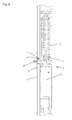
- Fig. 2 is a section of the drive housing 3 is shown with a drive 1 in a horizontal longitudinal section.
- the drive 1 has a motor unit 10, which may also include a transmission and control electronics.
- the guide contour 7 of the outlet element 6, the outlet guide 5 of the drive 1 receives, whereby the only determination takes place in the longitudinal direction within the drive housing 3.
- the outlet element 6 may have a gradation in the guide contour 7, so that after assembly in the outlet element 6 the same continuous inner contour is formed, as in the outlet guide 5, whereby an exact guidance of the actuating element 2 is present until it leaves the outlet element 6.
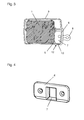
- the Fig. 3 shows a cross section through the drive housing 3 with mounted drive 1, which is guided in guides and webs in the drive housing 3 longitudinally displaceable.
- the outlet guide 5 is received in the outlet element 6, which is bolted here by means of Schenk screws with the profile of the drive housing 3.
- the end piece 8 is arranged on the retracted into the drive 1 actuator 2 and is beyond the outlet element 6 addition, whereby it can be fixed to the console on the wing or frame.
- Fig. 4 the exit element 6 is shown with the guide contour 7 in an enlarged view.
Landscapes
- Power-Operated Mechanisms For Wings (AREA)
- Window Of Vehicle (AREA)
Abstract
Description
Die Erfindung betrifft einen Antrieb eines Fensters, einer Klappe oder dergleichen nach dem Anspruch 1.The invention relates to a drive of a window, a flap or the like according to
Aus der
Nachteilig ist zur Festlegung der Antriebe eine aufwändige Spannvorrichtung erforderlich.A disadvantage is the setting of the drives an expensive clamping device required.
Der Erfindung liegt die Aufgabe zugrunde, eine einfache Möglichkeit zur Festlegung eines Antriebs in einem Antriebsgehäuse zu schaffen.The invention has for its object to provide a simple way to define a drive in a drive housing.
Die Aufgabe wird durch die Merkmale des Anspruchs 1 gelöst.The object is solved by the features of
Die Unteransprüche bilden vorteilhafte Ausgestaltungsmöglichkeiten der Erfindung.The subclaims form advantageous embodiments of the invention.
Die an sich bekannten Antriebe sind zum motorischen Öffnen und Schließen von beispielsweise Fenstern geeignet, wobei ein Betätigungselement, wie eine Kette, ein Seil oder ähnliches, zum Schwenken eines Flügels zwischen einer Offen- und einer Geschlossenstellung aus dem Antrieb heraus ausfahrbar bzw. in diesen hinein einziehbar ist. Der Antrieb kann dabei am Flügel und eine Konsole zur Aufnahme des äußeren Endes des Betätigungselements am Blendrahmen, oder umgekehrt, angeordnet sein. Für große und schwere Flügel ist es erforderlich, mehr als einen Antrieb vorzusehen. Um die Montage vor Ort zu erleichtern, sind die Antriebe vorteilhaft fertig vorbereitet in einem gemeinsamen Antriebsgehäuse angeordnet.The known drives are suitable for motorized opening and closing of, for example, windows, wherein an actuating element, such as a chain, a rope or the like, for pivoting a wing between an open and a closed position out of the drive extendable or in this is retractable. The drive can be on the wing and a console for receiving the outer end of the actuating element on the frame, or vice versa, be arranged. For large and heavy wings, it is necessary to provide more than one drive. To facilitate on-site assembly, the drives are advantageously ready prepared arranged in a common drive housing.
Das Antriebsgehäuse ist als Hohlprofil ausgebildet und kann zur Aufnahme von zwei oder mehr Antrieben vorgesehen sein. Die Antriebe werden von den Stirnseiten des Antriebsgehäuses her in das Hohlprofil eingeschoben, wobei im Hohlprofil angeordnete Führungen und Stege die Antriebe innerhalb des Hohlprofils in Längsrichtung führen können.The drive housing is designed as a hollow profile and can be provided for receiving two or more drives. The drives are inserted from the front sides of the drive housing forth in the hollow profile, wherein arranged in the hollow profile guides and webs can cause the drives within the hollow profile in the longitudinal direction.
In dem rechteckförmigen, geschlossenen Antriebsgehäuse sind Aussparungen vorgesehen, durch welche jeweils das Betätigungselement des zugeordneten Antriebs austreten kann. Die Aussparungen sind dabei nur wenig größer, als es für den Durchgriff des Betätigungselements erforderlich ist, um die Stabilität des Antriebsgehäuses nicht herabzusetzen.In the rectangular, closed drive housing recesses are provided, through which in each case the actuating element of the associated drive can emerge. The recesses are only slightly larger than is necessary for the passage of the actuating element in order not to reduce the stability of the drive housing.
Am jeweiligen Antrieb ist im Bereich des Austritts des Betätigungselements eine Austrittsführung vorgesehen, welche zur Positionierung des Antriebs im Antriebsgehäuse der Aussparung gegenüber gestellt wird. Die Festlegung und Sicherung des Antriebs in diese Position erfolgt schnell und sicher durch ein Austrittselement, das durch die Aussparung auf die Austrittsführung des Antriebs gesetzt wird. Die Aussparung begrenzt dabei den Durchgriff des Betätigungselements im Hohlprofil des Antriebsgehäuses allseitig mit einem Abstand zum Betätigungselement, wodurch das Austrittselement zur Fixierung des Antriebs im Antriebsgehäuse einsetzbar ist. Das Austrittselement nimmt zur exakten Positionierung die Austrittsführung in einer Führungskontur auf.At the respective drive an outlet guide is provided in the region of the outlet of the actuating element, which is provided for positioning of the drive in the drive housing of the recess opposite. The determination and securing of the drive in this position is done quickly and safely by an exit element, which is set by the recess on the outlet guide of the drive. The recess limits the penetration of the actuating element in the hollow profile of the drive housing on all sides with a distance from the actuating element, whereby the outlet element can be used to fix the drive in the drive housing. The outlet element accommodates the outlet guide in a guide contour for exact positioning.
Das Austrittselement ist beispielsweise mit Schrauben, Nieten oder durch eine Rastverbindung am Antriebsgehäuse festgelegt und ist das einzige Mittel zur Positionierung und Fixierung des Antriebs zumindest in der Längserstreckung des Antriebsgehäuses. Der Montageaufwand ist durch diese ausschließliche Positionierung und Festlegung des Antriebs erheblich reduziert. Zusätzlich wird vorteilhaft ein leichtes, geführtes Gleiten des Betätigungselements in der Führungskontur bewirkt, wenn ein Material mit günstigen Gleiteigenschaften gewählt wird. Nach erfolgter Montage kann noch ein Endstück am Betätigungselement angebracht werden, das der Anlenkung des Betätigungselements an die Konsole dient.The outlet element is fixed, for example with screws, rivets or by a latching connection on the drive housing and is the only means for positioning and fixing the drive, at least in the longitudinal extension of the drive housing. The assembly effort is significantly reduced by this exclusive positioning and fixing the drive. In addition, advantageously, a slight, guided sliding of the actuating element in the guide contour causes, if a material with favorable sliding properties is selected. After installation, an end piece can still be attached to the actuating element, which serves for the articulation of the actuating element to the console.
Das Antriebsgehäuse kann endseitig mit jeweils einem Seitendeckel verschlossen werden, der auch zur Durchführung einer Versorgungs- und Signalleitung zum elektrischen Anschluss der Antriebe geeignet ist.The drive housing can be closed at the ends, each with a side cover, which is also suitable for carrying a supply and signal line for the electrical connection of the drives.
Im Nachfolgenden wird ein Ausführungsbeispiel in der Zeichnung anhand der Figuren näher erläutert.In the following an embodiment in the drawing with reference to the figures will be explained in more detail.
Dabei zeigen:
- Fig. 1
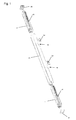
- eine Darstellung eines Antriebsgehäuses für zwei Antriebe vor der Montage;
- Fig. 2
- ein Ausschnitt des Antriebsgehäuses mit einem Antrieb in geschnittener Darstellung (Längsschnitt);
- Fig. 3
- einen Querschnitt durch das Antriebsgehäuse mit montiertem Antrieb;
- Fig. 4
- eine Schrägansicht auf ein Austrittselement.
- Fig. 1
- a representation of a drive housing for two drives before mounting;
- Fig. 2
- a section of the drive housing with a drive in a sectional view (longitudinal section);
- Fig. 3
- a cross section through the drive housing with mounted drive;
- Fig. 4
- an oblique view of an exit element.
Die an sich bekannten Antriebe 1 sind beispielsweise an Fenstern angeordnet, um ein motorisches Öffnen und Schließen eines in einem Blendrahmen schwenkbar gelagerten Flügels zu ermöglichen. Dazu kann der Antrieb 1 auf dem Flügel angeordnet sein, und eine Konsole, an welcher sich ein Betätigungselement 2 des Antriebs 1 abstützt, kann auf dem Blendrahmen angeordnet sein. Es ist auch die umgekehrte Anordnung möglich, wobei der Antrieb 1 auf dem Blendrahmen und die Konsole auf dem Flügel angeordnet ist.The known
Das Betätigungselement 2 ist zum Schwenken des Flügels zwischen einen Offen-und einer Geschlossenstellung zum Öffnen aus dem Antrieb 1 heraus ausfahrbar und zum Schließen in den Antrieb 1 hinein einziehbar. Für große und schwere Flügel ist es erforderlich, mehr als einen Antrieb 1 anzuordnen. Vorteilhaft werden dann die Antriebe 1 in einem gemeinsamen Antriebsgehäuse 3 angeordnet, um vorort die Montage zu vereinfachen. Die Antriebe 1 können dann über eine Steuerung synchron betätigt werden, um ein Verwinden des Flügels zu verhindern.The
In
Im Antriebsgehäuse 3 sind zwei Aussparungen 4 vorgesehen, durch welche jeweils ein Betätigungselement 2, wie z.B. eine Kette, des zugeordneten Antriebs 1 austreten kann. Am Antrieb 1 ist im Bereich des Austritts des Betätigungselements 2 eine Austrittsführung 5 vorgesehen. Die Aussparungen 4 sind etwas größer, als es für den Durchgriff des Betätigungselements notwendig ist, um die Stabilität des rechteckförmigen Hohlprofils des Antriebsgehäuses 3 nicht herabzusetzen. Die Aussparung kann rechteckförmig sein, aber auch kreisförmig oder unrund ausgebildet sein. Durch Einschieben des Antriebs 1 erfolgt die Positionierung im Antriebsgehäuse 3, indem die Austrittsführung 5 vor die Aussparung 4 geführt wird. Die Festlegung und Sicherung des Antriebs 1 nach dem Einschieben erfolgt ausschließlich durch ein Austrittselement 6, das in die zugeordnete, für das Austrittselement 6 passende Aussparung 4 eingesetzt wird, wobei das Austrittselement 6 die Austrittsführung 5 des Antriebs 1 in einer Führungskontur 7 aufnimmt. Das Austrittselement 6 ist beispielsweise mit Schrauben oder Nieten, welche in Bohrungen des Profis des Antriebsgehäuses 3 aufgenommen werden können, am Antriebsgehäuse 3 festgelegt. Besonders vorteilhaft kann das Austrittselement 6 am Antriebsgehäuse 3 festgelegt werden, indem das Austrittselement 6 mit einem Rastelement 13 versehen ist, welches in eine Längsnut 12 am Antriebsgehäuse 3 eingreift. In einer anderen Ausgestaltung können alternativ oder zusätzlich an der Führungskontur 7 ein oder mehrere Rastelemente 13 vorgesehen sein, welche die Profilwandung des Antriebsgehäuses 3 im Bereich der Aussparung 4 hintergreifen. Denkbar sind auch Rastelemente 13, die anstelle von Schrauben oder Nieten am Austrittselement 6 angeordnet sein können und in die Bohrungen im Antriebsgehäuse 3 eingreifen. Der Montageaufwand ist durch die ausschließliche Positionierung und Festlegung des Antriebs 1 im Antriebsgehäuse 3 mittels des Austrittselements 6 erheblich reduziert.In the
Besonders vorteilhaft dient das Austrittselement 6 neben der Positionierung und Festlegung des Antriebs 1 im Antriebsgehäuse 3 auch der Führung des Betätigungselements 2. Dazu weist das Austrittselement 6 eine Führungskontur 7 auf, welche zum Einen die Kanten der Aussparung 4 schützend abdeckt und zum Anderen ein leichtes, geführtes Gleiten des Betätigungselements 2 bewirkt. Insbesondere kann dazu auch ein Material gewählt sein, das günstige Gleiteigenschaften aufweist.Particularly advantageous is the
Nach erfolgter Montage kann ein Endstück 8 an das Betätigungselement 2 angebracht werden, welches zur Anbindung des Betätigungselements 2 an die Konsole zur Abstützung am Flügel oder am Blendrahmen dient. Weiterhin kann das Antriebsgehäuse 3 jeweils endseitig mit einem Seitendeckel 9, der mit Aussparungen zur Einführung einer Versorgungs- und Signalleitung zum elektrischen Anschluss der Antriebe 1 versehen sein kann, verschlossen sein.After installation, an
In
Die
In
- 11
- Antriebdrive
- 22
- Betätigungselementactuator
- 33
- Antriebsgehäusedrive housing
- 44
- Aussparungrecess
- 55
- Austrittsführungexit guide
- 66
- Austrittselementexit element
- 77
- Führungskonturguide contour
- 88th
- Endstücktail
- 99
- Seitendeckelside cover
- 1010
- Motoreinheitmotor unit
- 1111
- Antriebsritzelpinion
- 1212
- Längsnutlongitudinal groove
- 1313
- Rastelementlocking element
Claims (9)
dadurch gekennzeichnet,
dass das Antriebsgehäuse (3) als geschlossenes, rechteckförmiges Hohlprofil ausgebildet ist, wobei die Aussparung (4) den Durchgriff des Betätigungselements (2) im Hohlprofil des Antriebsgehäuses (3) allseitig beabstandet begrenzt, sodass der in das Hohlprofil einschiebbare Antrieb (1) mittels eines in die Aussparungen (4) einsetzbaren Austrittselements (6) im Antriebsgehäuse (3) festlegbar ist.Drive (1) a window, a flap or the like, with an actuating element (2) for pivoting a wing between an open and a closed position, with a drive housing (3), in which the drive (1) can be inserted, and with a Recess (4) for the passage of the actuating element (2);
characterized,
that the drive housing (3) is formed as a closed, rectangular hollow profile, wherein the recess (4) the passage of the actuating element (2) in the hollow profile of the drive housing (3) spaced on all sides limited, so that the insertable into the hollow profile drive (1) by means of a in the recesses (4) insertable outlet element (6) in the drive housing (3) can be fixed.
dadurch gekennzeichnet, dass der Antrieb (1) eine Austrittsführung (5) für das Betätigungselement (2) aufweist.Drive according to claim 1,
characterized in that the drive (1) has an outlet guide (5) for the actuating element (2).
dadurch gekennzeichnet, dass die Austrittsführung (5) in einer Führungskontur (7) des Austrittselements (6) zur Positionierung des Antriebs (1) und zur Führung des Betätigungselements (2) aufgenommen ist.Drive according to claim 2,
characterized in that the outlet guide (5) is received in a guide contour (7) of the outlet element (6) for positioning the drive (1) and for guiding the actuating element (2).
dadurch gekennzeichnet, dass zur exakten Führung des Betätigungselements (2) die Führungskontur (7) eine Abstufung aufweist, so dass eine durchgehende Innenkontur von Austrittsführung (5) und Austrittselement (6) ausgebildet ist.Drive according to claim 3,
characterized in that for the exact guidance of the actuating element (2) the guide contour (7) has a gradation, so that a continuous inner contour of the outlet guide (5) and outlet element (6) is formed.
dadurch gekennzeichnet, dass das Austrittselement (6) das einzige Mittel zur Positionierung und Fixierung des Antriebs (1) im Antriebsgehäuses (3) ist.Drive according to claim 1,
characterized in that the outlet element (6) is the only means for positioning and fixing the drive (1) in the drive housing (3).
dadurch gekennzeichnet, dass das Austrittselement (6) durch eine Rastverbindung am Antriebsgehäuse (1) festgelegt ist.Drive according to claim 1,
characterized in that the outlet element (6) is fixed by a latching connection on the drive housing (1).
dadurch gekennzeichnet, dass das Antriebsgehäuse (3) eine Längsnut (12) zur Aufnahme eines Rastelements (13) des Austrittselements (6) ausgebildet ist.Drive according to claim 6,
characterized in that the drive housing (3) is a longitudinal groove (12) for receiving a latching element (13) of the outlet element (6) is formed.
dadurch gekennzeichnet, dass an der Führungskontur (7) des Austrittselements (6) Rastelemente (13) angeordnet sind, welche in die Aussparung (4) zur Festlegung des Austrittselements (6) am Antriebsgehäuse (3) eingreifen.Drive according to claim 6,
characterized in that on the guide contour (7) of the outlet element (6) locking elements (13) are arranged, which engage in the recess (4) for fixing the outlet element (6) on the drive housing (3).
dadurch gekennzeichnet, dass die Rastverbindung des Austrittselement (6) in eine oder mehrere Bohrungen des Antriebsgehäuses (3) eingreift.Drive according to claim 6,
characterized in that the latching connection of the outlet element (6) engages in one or more bores of the drive housing (3).
Priority Applications (1)
| Application Number | Priority Date | Filing Date | Title |
|---|---|---|---|
| PL11157132T PL2365175T3 (en) | 2010-03-12 | 2011-03-07 | Drive for a window, flap or similar |
Applications Claiming Priority (1)
| Application Number | Priority Date | Filing Date | Title |
|---|---|---|---|
| DE102010002817.7A DE102010002817C5 (en) | 2010-03-12 | 2010-03-12 | Drive a window, a flap or the like |
Publications (3)
| Publication Number | Publication Date |
|---|---|
| EP2365175A2 true EP2365175A2 (en) | 2011-09-14 |
| EP2365175A3 EP2365175A3 (en) | 2014-08-06 |
| EP2365175B1 EP2365175B1 (en) | 2016-09-21 |
Family
ID=43877890
Family Applications (1)
| Application Number | Title | Priority Date | Filing Date |
|---|---|---|---|
| EP11157132.9A Active EP2365175B1 (en) | 2010-03-12 | 2011-03-07 | Drive for a window, flap or similar |
Country Status (3)
| Country | Link |
|---|---|
| EP (1) | EP2365175B1 (en) |
| DE (1) | DE102010002817C5 (en) |
| PL (1) | PL2365175T3 (en) |
Cited By (2)
| Publication number | Priority date | Publication date | Assignee | Title |
|---|---|---|---|---|
| CN106948703A (en) * | 2017-05-10 | 2017-07-14 | 宁波合力伟业消防科技有限公司 | Chain window-opening machine and window-opening mechanism |
| EP4177430A1 (en) * | 2021-11-04 | 2023-05-10 | EBm Konstruktioner AB | Device for actuating an openable and closable element, a system comprising the device and methods |
Families Citing this family (4)
| Publication number | Priority date | Publication date | Assignee | Title |
|---|---|---|---|---|
| DE202011050625U1 (en) * | 2011-07-04 | 2012-10-11 | D+H Mechatronic Ag | chain drive |
| DE102012203738B3 (en) * | 2012-03-09 | 2013-01-31 | Geze Gmbh | Drive device for window, has a circuit board holder having a fixed end cap which holds a pin engaged with recess formed in housing, and a holding frame having a recess for the passage of shaft of electric motor mounted with magnet |
| DE102017011091B4 (en) | 2017-11-30 | 2022-08-04 | Die Referenz für Antriebstechnik GmbH | Chain drive for loads such as windows or smoke vents |
| DE102018203295B3 (en) * | 2018-03-06 | 2019-08-14 | Geze Gmbh | Drive for a wing of a window or the like |
Citations (1)
| Publication number | Priority date | Publication date | Assignee | Title |
|---|---|---|---|---|
| EP1785570A2 (en) | 2005-11-10 | 2007-05-16 | TOPP S.p.A. | Chain-drive actuator assembly |
Family Cites Families (4)
| Publication number | Priority date | Publication date | Assignee | Title |
|---|---|---|---|---|
| DE4407276B4 (en) * | 1994-03-04 | 2005-04-28 | Geze Gmbh | Ausstellvorrichtung for a wing of a window, ventilation flap, dome light, door or the like and drive for moving two components relative to each other |
| DE60216414T3 (en) * | 2002-04-09 | 2010-09-09 | Vkr Holding A/S | Compact actuator |
| WO2005033455A1 (en) * | 2003-10-09 | 2005-04-14 | Vkr Holding A/S | Slim window actuator |
| EP2163717B1 (en) * | 2007-01-12 | 2015-10-28 | HAUTAU GmbH | End plug for the case of an actuating drive and device for fitting the case on a wing |
-
2010
- 2010-03-12 DE DE102010002817.7A patent/DE102010002817C5/en active Active
-
2011
- 2011-03-07 EP EP11157132.9A patent/EP2365175B1/en active Active
- 2011-03-07 PL PL11157132T patent/PL2365175T3/en unknown
Patent Citations (1)
| Publication number | Priority date | Publication date | Assignee | Title |
|---|---|---|---|---|
| EP1785570A2 (en) | 2005-11-10 | 2007-05-16 | TOPP S.p.A. | Chain-drive actuator assembly |
Cited By (3)
| Publication number | Priority date | Publication date | Assignee | Title |
|---|---|---|---|---|
| CN106948703A (en) * | 2017-05-10 | 2017-07-14 | 宁波合力伟业消防科技有限公司 | Chain window-opening machine and window-opening mechanism |
| EP4177430A1 (en) * | 2021-11-04 | 2023-05-10 | EBm Konstruktioner AB | Device for actuating an openable and closable element, a system comprising the device and methods |
| WO2023079009A1 (en) | 2021-11-04 | 2023-05-11 | Ebm Konstruktioner Ab | Device for actuating an openable and closable element, a system comprising the device and methods |
Also Published As
| Publication number | Publication date |
|---|---|
| PL2365175T3 (en) | 2017-08-31 |
| DE102010002817B3 (en) | 2011-05-19 |
| EP2365175A3 (en) | 2014-08-06 |
| DE102010002817C5 (en) | 2016-06-09 |
| EP2365175B1 (en) | 2016-09-21 |
Similar Documents
| Publication | Publication Date | Title |
|---|---|---|
| EP2604778B1 (en) | Folding sliding panel, drive and guide rail | |
| EP2365175B1 (en) | Drive for a window, flap or similar | |
| DE202007016531U1 (en) | Sliding window or sliding door | |
| DE202017100244U1 (en) | Shower partition with a by a spring-damper unit active in the end positions movable sliding door | |
| DE102011011113A1 (en) | Frame system of insect guard mounted in window and door of building, for preventing invasion of e.g. insect, has sliding element which is connected to guide plates along longitudinal rails of clamping element | |
| EP2639391A1 (en) | Sliding and pivoting leaf system | |
| EP1707726B1 (en) | Device for opening and closing a window or door slidably arranged on a frame | |
| DE202013009352U1 (en) | Window or door with a fitting | |
| EP2009215B1 (en) | Sensor device for a drive to operate a door or window | |
| EP2540616B1 (en) | Closing mechanism for a sliding door that closes with power assistance | |
| DE19819558A1 (en) | Automatic door installation with reduced structural height and simultaneously reduced horizontal structural depth | |
| DE102005051997B4 (en) | gate | |
| DE19934229A1 (en) | Lintel arrangement for an automatic sliding door | |
| DE1555632C3 (en) | ||
| DE10346861B4 (en) | A stay mechanism | |
| DE102012202981A1 (en) | Fitting for wing of e.g. sliding window, has adjusting arms rotatably arranged at carriages around vertical rotational axis and coupled with each other by coupling element e.g. coupling rod, where carriages move along guide | |
| DE102012218887B4 (en) | Closing piece for a window, a door or the like | |
| DE202009008840U1 (en) | door | |
| DE202019002391U1 (en) | Fitting system for a movable sash as sliding sash or sliding lifting sash of a window or door | |
| DE202007012981U1 (en) | Adjustment device for a cover device in a motor vehicle | |
| DE102020206316B4 (en) | DRIVE | |
| DE102007021706B4 (en) | Drive device for adjusting units in vehicle doors | |
| DE102011055196B4 (en) | cover | |
| DE202012004078U1 (en) | Lift guidance system for a car curtain | |
| DE102009060144B4 (en) | Device for actuating a tilt gate |
Legal Events
| Date | Code | Title | Description |
|---|---|---|---|
| PUAI | Public reference made under article 153(3) epc to a published international application that has entered the european phase |
Free format text: ORIGINAL CODE: 0009012 |
|
| AK | Designated contracting states |
Kind code of ref document: A2 Designated state(s): AL AT BE BG CH CY CZ DE DK EE ES FI FR GB GR HR HU IE IS IT LI LT LU LV MC MK MT NL NO PL PT RO RS SE SI SK SM TR |
|
| AX | Request for extension of the european patent |
Extension state: BA ME |
|
| PUAL | Search report despatched |
Free format text: ORIGINAL CODE: 0009013 |
|
| AK | Designated contracting states |
Kind code of ref document: A3 Designated state(s): AL AT BE BG CH CY CZ DE DK EE ES FI FR GB GR HR HU IE IS IT LI LT LU LV MC MK MT NL NO PL PT RO RS SE SI SK SM TR |
|
| AX | Request for extension of the european patent |
Extension state: BA ME |
|
| RIC1 | Information provided on ipc code assigned before grant |
Ipc: E05F 15/12 20060101ALI20140629BHEP Ipc: E05F 11/06 20060101AFI20140629BHEP |
|
| 17P | Request for examination filed |
Effective date: 20150203 |
|
| RBV | Designated contracting states (corrected) |
Designated state(s): AL AT BE BG CH CY CZ DE DK EE ES FI FR GB GR HR HU IE IS IT LI LT LU LV MC MK MT NL NO PL PT RO RS SE SI SK SM TR |
|
| REG | Reference to a national code |
Ref country code: DE Ref legal event code: R079 Ref document number: 502011010713 Country of ref document: DE Free format text: PREVIOUS MAIN CLASS: E05F0011060000 Ipc: E05F0015619000 |
|
| RIC1 | Information provided on ipc code assigned before grant |
Ipc: E05F 15/619 20150101AFI20160322BHEP Ipc: E05F 11/06 20060101ALI20160322BHEP |
|
| GRAP | Despatch of communication of intention to grant a patent |
Free format text: ORIGINAL CODE: EPIDOSNIGR1 |
|
| INTG | Intention to grant announced |
Effective date: 20160502 |
|
| GRAS | Grant fee paid |
Free format text: ORIGINAL CODE: EPIDOSNIGR3 |
|
| GRAA | (expected) grant |
Free format text: ORIGINAL CODE: 0009210 |
|
| AK | Designated contracting states |
Kind code of ref document: B1 Designated state(s): AL AT BE BG CH CY CZ DE DK EE ES FI FR GB GR HR HU IE IS IT LI LT LU LV MC MK MT NL NO PL PT RO RS SE SI SK SM TR |
|
| REG | Reference to a national code |
Ref country code: GB Ref legal event code: FG4D Free format text: NOT ENGLISH |
|
| REG | Reference to a national code |
Ref country code: CH Ref legal event code: EP |
|
| REG | Reference to a national code |
Ref country code: AT Ref legal event code: REF Ref document number: 831220 Country of ref document: AT Kind code of ref document: T Effective date: 20161015 |
|
| REG | Reference to a national code |
Ref country code: IE Ref legal event code: FG4D Free format text: LANGUAGE OF EP DOCUMENT: GERMAN |
|
| REG | Reference to a national code |
Ref country code: DE Ref legal event code: R096 Ref document number: 502011010713 Country of ref document: DE |
|
| REG | Reference to a national code |
Ref country code: LT Ref legal event code: MG4D Ref country code: NL Ref legal event code: MP Effective date: 20160921 |
|
| PG25 | Lapsed in a contracting state [announced via postgrant information from national office to epo] |
Ref country code: LT Free format text: LAPSE BECAUSE OF FAILURE TO SUBMIT A TRANSLATION OF THE DESCRIPTION OR TO PAY THE FEE WITHIN THE PRESCRIBED TIME-LIMIT Effective date: 20160921 Ref country code: RS Free format text: LAPSE BECAUSE OF FAILURE TO SUBMIT A TRANSLATION OF THE DESCRIPTION OR TO PAY THE FEE WITHIN THE PRESCRIBED TIME-LIMIT Effective date: 20160921 Ref country code: NO Free format text: LAPSE BECAUSE OF FAILURE TO SUBMIT A TRANSLATION OF THE DESCRIPTION OR TO PAY THE FEE WITHIN THE PRESCRIBED TIME-LIMIT Effective date: 20161221 Ref country code: FI Free format text: LAPSE BECAUSE OF FAILURE TO SUBMIT A TRANSLATION OF THE DESCRIPTION OR TO PAY THE FEE WITHIN THE PRESCRIBED TIME-LIMIT Effective date: 20160921 |
|
| PG25 | Lapsed in a contracting state [announced via postgrant information from national office to epo] |
Ref country code: NL Free format text: LAPSE BECAUSE OF FAILURE TO SUBMIT A TRANSLATION OF THE DESCRIPTION OR TO PAY THE FEE WITHIN THE PRESCRIBED TIME-LIMIT Effective date: 20160921 Ref country code: GR Free format text: LAPSE BECAUSE OF FAILURE TO SUBMIT A TRANSLATION OF THE DESCRIPTION OR TO PAY THE FEE WITHIN THE PRESCRIBED TIME-LIMIT Effective date: 20161222 Ref country code: LV Free format text: LAPSE BECAUSE OF FAILURE TO SUBMIT A TRANSLATION OF THE DESCRIPTION OR TO PAY THE FEE WITHIN THE PRESCRIBED TIME-LIMIT Effective date: 20160921 Ref country code: SE Free format text: LAPSE BECAUSE OF FAILURE TO SUBMIT A TRANSLATION OF THE DESCRIPTION OR TO PAY THE FEE WITHIN THE PRESCRIBED TIME-LIMIT Effective date: 20160921 |
|
| REG | Reference to a national code |
Ref country code: FR Ref legal event code: PLFP Year of fee payment: 7 |
|
| PG25 | Lapsed in a contracting state [announced via postgrant information from national office to epo] |
Ref country code: EE Free format text: LAPSE BECAUSE OF FAILURE TO SUBMIT A TRANSLATION OF THE DESCRIPTION OR TO PAY THE FEE WITHIN THE PRESCRIBED TIME-LIMIT Effective date: 20160921 Ref country code: RO Free format text: LAPSE BECAUSE OF FAILURE TO SUBMIT A TRANSLATION OF THE DESCRIPTION OR TO PAY THE FEE WITHIN THE PRESCRIBED TIME-LIMIT Effective date: 20160921 |
|
| PG25 | Lapsed in a contracting state [announced via postgrant information from national office to epo] |
Ref country code: PT Free format text: LAPSE BECAUSE OF FAILURE TO SUBMIT A TRANSLATION OF THE DESCRIPTION OR TO PAY THE FEE WITHIN THE PRESCRIBED TIME-LIMIT Effective date: 20170123 Ref country code: BG Free format text: LAPSE BECAUSE OF FAILURE TO SUBMIT A TRANSLATION OF THE DESCRIPTION OR TO PAY THE FEE WITHIN THE PRESCRIBED TIME-LIMIT Effective date: 20161221 Ref country code: SM Free format text: LAPSE BECAUSE OF FAILURE TO SUBMIT A TRANSLATION OF THE DESCRIPTION OR TO PAY THE FEE WITHIN THE PRESCRIBED TIME-LIMIT Effective date: 20160921 Ref country code: IS Free format text: LAPSE BECAUSE OF FAILURE TO SUBMIT A TRANSLATION OF THE DESCRIPTION OR TO PAY THE FEE WITHIN THE PRESCRIBED TIME-LIMIT Effective date: 20170121 Ref country code: CZ Free format text: LAPSE BECAUSE OF FAILURE TO SUBMIT A TRANSLATION OF THE DESCRIPTION OR TO PAY THE FEE WITHIN THE PRESCRIBED TIME-LIMIT Effective date: 20160921 Ref country code: SK Free format text: LAPSE BECAUSE OF FAILURE TO SUBMIT A TRANSLATION OF THE DESCRIPTION OR TO PAY THE FEE WITHIN THE PRESCRIBED TIME-LIMIT Effective date: 20160921 Ref country code: ES Free format text: LAPSE BECAUSE OF FAILURE TO SUBMIT A TRANSLATION OF THE DESCRIPTION OR TO PAY THE FEE WITHIN THE PRESCRIBED TIME-LIMIT Effective date: 20160921 |
|
| REG | Reference to a national code |
Ref country code: DE Ref legal event code: R097 Ref document number: 502011010713 Country of ref document: DE |
|
| PG25 | Lapsed in a contracting state [announced via postgrant information from national office to epo] |
Ref country code: IT Free format text: LAPSE BECAUSE OF FAILURE TO SUBMIT A TRANSLATION OF THE DESCRIPTION OR TO PAY THE FEE WITHIN THE PRESCRIBED TIME-LIMIT Effective date: 20160921 |
|
| PLBE | No opposition filed within time limit |
Free format text: ORIGINAL CODE: 0009261 |
|
| STAA | Information on the status of an ep patent application or granted ep patent |
Free format text: STATUS: NO OPPOSITION FILED WITHIN TIME LIMIT |
|
| PG25 | Lapsed in a contracting state [announced via postgrant information from national office to epo] |
Ref country code: DK Free format text: LAPSE BECAUSE OF FAILURE TO SUBMIT A TRANSLATION OF THE DESCRIPTION OR TO PAY THE FEE WITHIN THE PRESCRIBED TIME-LIMIT Effective date: 20160921 |
|
| 26N | No opposition filed |
Effective date: 20170622 |
|
| REG | Reference to a national code |
Ref country code: CH Ref legal event code: PL |
|
| PG25 | Lapsed in a contracting state [announced via postgrant information from national office to epo] |
Ref country code: MC Free format text: LAPSE BECAUSE OF FAILURE TO SUBMIT A TRANSLATION OF THE DESCRIPTION OR TO PAY THE FEE WITHIN THE PRESCRIBED TIME-LIMIT Effective date: 20160921 Ref country code: SI Free format text: LAPSE BECAUSE OF FAILURE TO SUBMIT A TRANSLATION OF THE DESCRIPTION OR TO PAY THE FEE WITHIN THE PRESCRIBED TIME-LIMIT Effective date: 20160921 |
|
| REG | Reference to a national code |
Ref country code: IE Ref legal event code: MM4A |
|
| PG25 | Lapsed in a contracting state [announced via postgrant information from national office to epo] |
Ref country code: LU Free format text: LAPSE BECAUSE OF NON-PAYMENT OF DUE FEES Effective date: 20170307 |
|
| PG25 | Lapsed in a contracting state [announced via postgrant information from national office to epo] |
Ref country code: LI Free format text: LAPSE BECAUSE OF NON-PAYMENT OF DUE FEES Effective date: 20170331 Ref country code: CH Free format text: LAPSE BECAUSE OF NON-PAYMENT OF DUE FEES Effective date: 20170331 Ref country code: IE Free format text: LAPSE BECAUSE OF NON-PAYMENT OF DUE FEES Effective date: 20170307 |
|
| REG | Reference to a national code |
Ref country code: BE Ref legal event code: MM Effective date: 20170331 |
|
| REG | Reference to a national code |
Ref country code: FR Ref legal event code: PLFP Year of fee payment: 8 |
|
| PG25 | Lapsed in a contracting state [announced via postgrant information from national office to epo] |
Ref country code: BE Free format text: LAPSE BECAUSE OF NON-PAYMENT OF DUE FEES Effective date: 20170331 |
|
| PG25 | Lapsed in a contracting state [announced via postgrant information from national office to epo] |
Ref country code: MT Free format text: LAPSE BECAUSE OF FAILURE TO SUBMIT A TRANSLATION OF THE DESCRIPTION OR TO PAY THE FEE WITHIN THE PRESCRIBED TIME-LIMIT Effective date: 20160921 |
|
| PG25 | Lapsed in a contracting state [announced via postgrant information from national office to epo] |
Ref country code: AL Free format text: LAPSE BECAUSE OF FAILURE TO SUBMIT A TRANSLATION OF THE DESCRIPTION OR TO PAY THE FEE WITHIN THE PRESCRIBED TIME-LIMIT Effective date: 20160921 |
|
| PG25 | Lapsed in a contracting state [announced via postgrant information from national office to epo] |
Ref country code: HU Free format text: LAPSE BECAUSE OF FAILURE TO SUBMIT A TRANSLATION OF THE DESCRIPTION OR TO PAY THE FEE WITHIN THE PRESCRIBED TIME-LIMIT; INVALID AB INITIO Effective date: 20110307 |
|
| PG25 | Lapsed in a contracting state [announced via postgrant information from national office to epo] |
Ref country code: CY Free format text: LAPSE BECAUSE OF NON-PAYMENT OF DUE FEES Effective date: 20160921 |
|
| PG25 | Lapsed in a contracting state [announced via postgrant information from national office to epo] |
Ref country code: MK Free format text: LAPSE BECAUSE OF FAILURE TO SUBMIT A TRANSLATION OF THE DESCRIPTION OR TO PAY THE FEE WITHIN THE PRESCRIBED TIME-LIMIT Effective date: 20160921 |
|
| PG25 | Lapsed in a contracting state [announced via postgrant information from national office to epo] |
Ref country code: TR Free format text: LAPSE BECAUSE OF FAILURE TO SUBMIT A TRANSLATION OF THE DESCRIPTION OR TO PAY THE FEE WITHIN THE PRESCRIBED TIME-LIMIT Effective date: 20160921 |
|
| PG25 | Lapsed in a contracting state [announced via postgrant information from national office to epo] |
Ref country code: HR Free format text: LAPSE BECAUSE OF FAILURE TO SUBMIT A TRANSLATION OF THE DESCRIPTION OR TO PAY THE FEE WITHIN THE PRESCRIBED TIME-LIMIT Effective date: 20160921 |
|
| PGFP | Annual fee paid to national office [announced via postgrant information from national office to epo] |
Ref country code: FR Payment date: 20230322 Year of fee payment: 13 |
|
| PGFP | Annual fee paid to national office [announced via postgrant information from national office to epo] |
Ref country code: PL Payment date: 20230228 Year of fee payment: 13 Ref country code: GB Payment date: 20230321 Year of fee payment: 13 |
|
| P01 | Opt-out of the competence of the unified patent court (upc) registered |
Effective date: 20230510 |
|
| PGFP | Annual fee paid to national office [announced via postgrant information from national office to epo] |
Ref country code: AT Payment date: 20240321 Year of fee payment: 14 |
|
| PGFP | Annual fee paid to national office [announced via postgrant information from national office to epo] |
Ref country code: DE Payment date: 20240331 Year of fee payment: 14 |