EP2365162A2 - Ein Schirm mit hohen Verwendbarkeit - Google Patents
Ein Schirm mit hohen Verwendbarkeit Download PDFInfo
- Publication number
- EP2365162A2 EP2365162A2 EP11157713A EP11157713A EP2365162A2 EP 2365162 A2 EP2365162 A2 EP 2365162A2 EP 11157713 A EP11157713 A EP 11157713A EP 11157713 A EP11157713 A EP 11157713A EP 2365162 A2 EP2365162 A2 EP 2365162A2
- Authority
- EP
- European Patent Office
- Prior art keywords
- plate
- elements
- shield according
- fluid
- shield
- Prior art date
- Legal status (The legal status is an assumption and is not a legal conclusion. Google has not performed a legal analysis and makes no representation as to the accuracy of the status listed.)
- Withdrawn
Links
- 239000012530 fluid Substances 0.000 claims abstract description 18
- 238000005086 pumping Methods 0.000 claims description 6
- 238000009825 accumulation Methods 0.000 claims description 4
- 239000000523 sample Substances 0.000 claims description 2
- 230000004308 accommodation Effects 0.000 claims 1
- XLYOFNOQVPJJNP-UHFFFAOYSA-N water Substances O XLYOFNOQVPJJNP-UHFFFAOYSA-N 0.000 description 4
- XEEYBQQBJWHFJM-UHFFFAOYSA-N Iron Chemical compound [Fe] XEEYBQQBJWHFJM-UHFFFAOYSA-N 0.000 description 2
- 230000005611 electricity Effects 0.000 description 2
- 238000010438 heat treatment Methods 0.000 description 2
- 230000000670 limiting effect Effects 0.000 description 2
- 239000000463 material Substances 0.000 description 2
- RYGMFSIKBFXOCR-UHFFFAOYSA-N Copper Chemical compound [Cu] RYGMFSIKBFXOCR-UHFFFAOYSA-N 0.000 description 1
- 229920004142 LEXAN™ Polymers 0.000 description 1
- XAGFODPZIPBFFR-UHFFFAOYSA-N aluminium Chemical compound [Al] XAGFODPZIPBFFR-UHFFFAOYSA-N 0.000 description 1
- 229910052782 aluminium Inorganic materials 0.000 description 1
- 238000009835 boiling Methods 0.000 description 1
- 230000005465 channeling Effects 0.000 description 1
- 229910052802 copper Inorganic materials 0.000 description 1
- 239000010949 copper Substances 0.000 description 1
- 239000008236 heating water Substances 0.000 description 1
- 229910052742 iron Inorganic materials 0.000 description 1
- 230000004048 modification Effects 0.000 description 1
- 238000012986 modification Methods 0.000 description 1
Images

Classifications
-
- E—FIXED CONSTRUCTIONS
- E04—BUILDING
- E04H—BUILDINGS OR LIKE STRUCTURES FOR PARTICULAR PURPOSES; SWIMMING OR SPLASH BATHS OR POOLS; MASTS; FENCING; TENTS OR CANOPIES, IN GENERAL
- E04H17/00—Fencing, e.g. fences, enclosures, corrals
- E04H17/14—Fences constructed of rigid elements, e.g. with additional wire fillings or with posts
- E04H17/1413—Post-and-rail fences, e.g. without vertical cross-members
-
- F—MECHANICAL ENGINEERING; LIGHTING; HEATING; WEAPONS; BLASTING
- F24—HEATING; RANGES; VENTILATING
- F24S—SOLAR HEAT COLLECTORS; SOLAR HEAT SYSTEMS
- F24S10/00—Solar heat collectors using working fluids
- F24S10/70—Solar heat collectors using working fluids the working fluids being conveyed through tubular absorbing conduits
- F24S10/75—Solar heat collectors using working fluids the working fluids being conveyed through tubular absorbing conduits with enlarged surfaces, e.g. with protrusions or corrugations
- F24S10/755—Solar heat collectors using working fluids the working fluids being conveyed through tubular absorbing conduits with enlarged surfaces, e.g. with protrusions or corrugations the conduits being otherwise bent, e.g. zig-zag
-
- F—MECHANICAL ENGINEERING; LIGHTING; HEATING; WEAPONS; BLASTING
- F24—HEATING; RANGES; VENTILATING
- F24S—SOLAR HEAT COLLECTORS; SOLAR HEAT SYSTEMS
- F24S20/00—Solar heat collectors specially adapted for particular uses or environments
- F24S20/60—Solar heat collectors integrated in fixed constructions, e.g. in buildings
- F24S20/62—Solar heat collectors integrated in fixed constructions, e.g. in buildings in the form of fences, balustrades or handrails
-
- F—MECHANICAL ENGINEERING; LIGHTING; HEATING; WEAPONS; BLASTING
- F24—HEATING; RANGES; VENTILATING
- F24S—SOLAR HEAT COLLECTORS; SOLAR HEAT SYSTEMS
- F24S20/00—Solar heat collectors specially adapted for particular uses or environments
- F24S20/60—Solar heat collectors integrated in fixed constructions, e.g. in buildings
- F24S20/66—Solar heat collectors integrated in fixed constructions, e.g. in buildings in the form of facade constructions, e.g. wall constructions
-
- Y—GENERAL TAGGING OF NEW TECHNOLOGICAL DEVELOPMENTS; GENERAL TAGGING OF CROSS-SECTIONAL TECHNOLOGIES SPANNING OVER SEVERAL SECTIONS OF THE IPC; TECHNICAL SUBJECTS COVERED BY FORMER USPC CROSS-REFERENCE ART COLLECTIONS [XRACs] AND DIGESTS
- Y02—TECHNOLOGIES OR APPLICATIONS FOR MITIGATION OR ADAPTATION AGAINST CLIMATE CHANGE
- Y02B—CLIMATE CHANGE MITIGATION TECHNOLOGIES RELATED TO BUILDINGS, e.g. HOUSING, HOUSE APPLIANCES OR RELATED END-USER APPLICATIONS
- Y02B10/00—Integration of renewable energy sources in buildings
- Y02B10/20—Solar thermal
-
- Y—GENERAL TAGGING OF NEW TECHNOLOGICAL DEVELOPMENTS; GENERAL TAGGING OF CROSS-SECTIONAL TECHNOLOGIES SPANNING OVER SEVERAL SECTIONS OF THE IPC; TECHNICAL SUBJECTS COVERED BY FORMER USPC CROSS-REFERENCE ART COLLECTIONS [XRACs] AND DIGESTS
- Y02—TECHNOLOGIES OR APPLICATIONS FOR MITIGATION OR ADAPTATION AGAINST CLIMATE CHANGE
- Y02E—REDUCTION OF GREENHOUSE GAS [GHG] EMISSIONS, RELATED TO ENERGY GENERATION, TRANSMISSION OR DISTRIBUTION
- Y02E10/00—Energy generation through renewable energy sources
- Y02E10/40—Solar thermal energy, e.g. solar towers
- Y02E10/44—Heat exchange systems
Definitions
- the present invention relates to a shield with high versatility. More specifically, the invention relates to a shield that is capable of acting as a normal perimeter fence and as a solar panel, or as a sunbreaker for buildings and as a solar panel.
- Solar panels are generally used on the roofs of buildings to collect the incident solar rays and convert the solar energy to electricity and/or heat.
- each building is usually provided with a perimeter fence that delimits the surface belonging to the building and prevents unauthorised access thereto.
- Such solar protection measures are usually constituted by support posts that are connected to each other by slats of various dimensions, fixed or mobile, or sliding, or even photovoltaic slats.
- the inclination of such slats can be varied in order to screen out sunlight or allow it to stream through, according to requirements.
- the aim of the present invention is to provide a shield that is highly reliable and which makes it possible to combine the function of perimeter fence with a function of producing hot water or a function of sunbreaker with the function of producing hot water.
- an object of the present invention is to provide a shield that makes it possible to exploit solar energy in both winter and summer.
- Another object of the present invention is to provide a shield that is highly reliable, easy to implement and at low cost.
- a shield comprising a pair of vertical posts connected by one or more plate-like elements, characterized in that each one of said plate-like elements accommodates heat exchange means adapted to allow the flow of a fluid to be heated, said fluid being conveyed within said plate-like elements through said vertical posts.
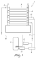
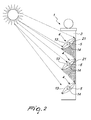
- the shield according to the present invention comprises a pair of vertical posts 2 and 3, which respectively support a plurality of plate-like elements 4 which are substantially oblong in cross-section, as shown in Figure 2 , or which have a different cross-section, for example rectangular, as shown in Figure 3 .
- Each plate-like element 4 accommodates within it heat exchange means 5 which allow the flow of a fluid internally.
- Figure 1 shows, with reference to the use of the invention as a fence, the circulation of the fluid which is pumped by pumping means 6 connected to accumulation means 7 and controlled by a controller 8.
- the pumping means 6 pump the fluid along a delivery path 9 within the post 3, which is connected to the heat exchanger accommodated inside the plate-like element 4 arranged lowest, near the ground. From the first plate-like element 4 the fluid flows into the second plate-like element, passing through the post 2, and proceeds, in a coiled manner, up until the highest plate-like element 4 and, from such element, it returns inside the post 2 in order to follow a return path 10 and flow into the accumulation means 7.
- At least one probe 11 is provided for detecting the temperature of the fluid, which preferably is water.
- each plate-like element constitutes a sort of fin which is arranged at an angle for example between 40° and 60° with respect to the horizontal, so as to be able to catch the sun rays both in winter, when the rays strike the Earth surface at an angle of 30° with respect to the Earth axis, and in summer, i.e. from April to September, when the sun rays have a different angle of incidence from that in winter.
- the above mentioned angle makes it possible, in summer, to have a partial shielding of the plate-like elements, so as to prevent the fluid that flows in the plate-like elements from excessively heating up and therefore boiling.
- the selected angle makes it possible to maintain a temperature of around 70°, which is useful for the aim of the invention.
- each plate-like element 4 is covered, on its surface that is designed to be faced towards the sun, by a high-transparency film 13, for example Lexan®, while the other side of the plate-like element is covered with a shielding film 14.
- a high-transparency film 13 for example Lexan®
- the plate-like element 4 is made with a reduced cross-section, and therefore has a reduced thickness, so as to have the greatest possible exchange of heat.
- the maximum cross-section of the plate-like element 4 is determined by the possibility of accommodating the heat exchange means 5 internally.
- Each plate-like element 4 internally accommodates a plate 21 that separates the plate-like element 4 substantially into two halves and which passes through the heat exchanger 5, so as to increase the heat exchange surface.
- the fluid that flows into the heat exchanger 5 is separated into two parts which flow into each of the two halves into which the heat exchanger 5 is divided by the plate 21.
- the fluid thus comes into contact not only with the circumference portion of the heat exchanger 5, but also with the portion of plate 21 that passes through the exchanger.
- the plate-like element 4 is substantially constituted by a covering housing 20 which accommodates the heat exchange means 5 and the plate 21 internally.
- the plate-like elements 4 can be made of different materials (iron, copper, aluminum etc.), as well as, obviously, in several different lengths and shapes.
- the shield according to the invention can perform both the function of normal fence and also the function of heating water as would happen with a normal solar panel.
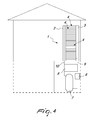
- the shield according to the invention can be used as a sunbreaker for buildings, as illustrated in Figures 3 and 4 .
- the side posts 2 and 3 are provided with fixing plates 15 and 16.
- plate-like elements there can be a variable number of plate-like elements, for example a single, large plate-like element can be provided, with an internal channeling that acts as a heat exchanger, or a plurality of plate-like elements can be provided, arranged side-by-side, as shown in the Figures.
Landscapes
- Engineering & Computer Science (AREA)
- Chemical & Material Sciences (AREA)
- Mechanical Engineering (AREA)
- General Engineering & Computer Science (AREA)
- Sustainable Energy (AREA)
- Thermal Sciences (AREA)
- Life Sciences & Earth Sciences (AREA)
- Combustion & Propulsion (AREA)
- Physics & Mathematics (AREA)
- Sustainable Development (AREA)
- Architecture (AREA)
- Civil Engineering (AREA)
- Structural Engineering (AREA)
- Dispersion Chemistry (AREA)
- Physical Or Chemical Processes And Apparatus (AREA)
- Heat-Exchange Devices With Radiators And Conduit Assemblies (AREA)
- Buildings Adapted To Withstand Abnormal External Influences (AREA)
Applications Claiming Priority (2)
| Application Number | Priority Date | Filing Date | Title |
|---|---|---|---|
| IT000400A ITMI20100400A1 (it) | 2010-03-12 | 2010-03-12 | Struttura di recinzione ad elevata versatilità. |
| IT000726A ITMI20100726A1 (it) | 2010-04-28 | 2010-04-28 | Struttura di frangisole, particolarmente per facciate di edifici e simili. |
Publications (2)
| Publication Number | Publication Date |
|---|---|
| EP2365162A2 true EP2365162A2 (de) | 2011-09-14 |
| EP2365162A3 EP2365162A3 (de) | 2011-11-16 |
Family
ID=43760053
Family Applications (1)
| Application Number | Title | Priority Date | Filing Date |
|---|---|---|---|
| EP11157713A Withdrawn EP2365162A3 (de) | 2010-03-12 | 2011-03-10 | Ein Schirm mit hohen Verwendbarkeit |
Country Status (1)
| Country | Link |
|---|---|
| EP (1) | EP2365162A3 (de) |
Family Cites Families (3)
| Publication number | Priority date | Publication date | Assignee | Title |
|---|---|---|---|---|
| EP0175836B1 (de) * | 1984-09-18 | 1989-03-15 | Sharp Kabushiki Kaisha | Heizungssystem mit Sonnenkollektoren |
| DE20209893U1 (de) * | 2002-06-26 | 2002-10-17 | Grychtolik, Alexander, 13156 Berlin | Lamellen-Sonnenkollektor |
| US20100051020A1 (en) * | 2008-08-29 | 2010-03-04 | William Robert Haas | Solar absorber fence system |
-
2011
- 2011-03-10 EP EP11157713A patent/EP2365162A3/de not_active Withdrawn
Non-Patent Citations (1)
| Title |
|---|
| None |
Also Published As
| Publication number | Publication date |
|---|---|
| EP2365162A3 (de) | 2011-11-16 |
Similar Documents
| Publication | Publication Date | Title |
|---|---|---|
| US20160072429A1 (en) | Pool solar power generator | |
| KR102825337B1 (ko) | 태양 에너지 지붕 타일, 태양 에너지 시스템 및 태양 복사로부터 에너지를 얻는 방법 | |
| US9407198B2 (en) | Support structure for solar panel | |
| EP2645013A1 (de) | System mit Tafeln zur Solarenergieumwandlung auf vertikalen Oberflächen | |
| KR101471050B1 (ko) | 음영지역이 해소되는 태양광 발전장치 | |
| ITTO20070348A1 (it) | Pannello di captazione di energia solare per tetti e simili | |
| CA2777270A1 (en) | Wall assembly with photovoltaic panel | |
| EP2365162A2 (de) | Ein Schirm mit hohen Verwendbarkeit | |
| WO2014070626A1 (en) | Sunshade with intergrated solar thermal collector | |
| KR101594001B1 (ko) | 발코니 난간에 설치된 태양열집열장치 | |
| JP2014053378A (ja) | 高効率発電ユニット及び高効率発電アレイ | |
| WO2010109508A2 (en) | Concentrating solar panel installation with azimuth orientation system | |
| KR20190143093A (ko) | 태양광 발전 차양 | |
| RU2557272C1 (ru) | Кровельная солнечная панель | |
| JP3177700U (ja) | 太陽電池パネルの自然冷却 | |
| KR101114504B1 (ko) | 공동주택용으로 태양광과 태양열을 동시적용하는 태양에너지장치의 과열방지구조 | |
| KR101080901B1 (ko) | 다방향성 에너지 흡수형 태양광발전모듈 | |
| WO2002053990A1 (en) | Covering element for roofs and walls of buildings | |
| Souliotis et al. | Experimental study of a thermosiphonic hybrid PV/T solar system | |
| EP2144013A1 (de) | Thermohydraulisches System und Betriebsverfahren davon | |
| WO2007045933A1 (en) | Pergola solar collector system constructed from long heating elements | |
| RU2738738C1 (ru) | Планарная кровельная панель с гофрированным тепловым фотоприёмником | |
| CN104481095A (zh) | 太阳能护栏 | |
| KR100879393B1 (ko) | 태양광 반사장치 | |
| CN213602581U (zh) | 一种太阳能电池板用保护结构 |
Legal Events
| Date | Code | Title | Description |
|---|---|---|---|
| PUAI | Public reference made under article 153(3) epc to a published international application that has entered the european phase |
Free format text: ORIGINAL CODE: 0009012 |
|
| AK | Designated contracting states |
Kind code of ref document: A2 Designated state(s): AL AT BE BG CH CY CZ DE DK EE ES FI FR GB GR HR HU IE IS IT LI LT LU LV MC MK MT NL NO PL PT RO RS SE SI SK SM TR |
|
| AX | Request for extension of the european patent |
Extension state: BA ME |
|
| PUAL | Search report despatched |
Free format text: ORIGINAL CODE: 0009013 |
|
| AK | Designated contracting states |
Kind code of ref document: A3 Designated state(s): AL AT BE BG CH CY CZ DE DK EE ES FI FR GB GR HR HU IE IS IT LI LT LU LV MC MK MT NL NO PL PT RO RS SE SI SK SM TR |
|
| AX | Request for extension of the european patent |
Extension state: BA ME |
|
| RIC1 | Information provided on ipc code assigned before grant |
Ipc: F24J 2/24 20060101ALI20111012BHEP Ipc: F24J 2/05 20060101ALI20111012BHEP Ipc: F24J 2/04 20060101ALI20111012BHEP Ipc: F24J 2/00 20060101ALI20111012BHEP Ipc: E04H 17/14 20060101AFI20111012BHEP |
|
| STAA | Information on the status of an ep patent application or granted ep patent |
Free format text: STATUS: THE APPLICATION IS DEEMED TO BE WITHDRAWN |
|
| 18D | Application deemed to be withdrawn |
Effective date: 20120517 |