EP2364583A1 - Landwirtschaftliche Verteilmaschine - Google Patents
Landwirtschaftliche Verteilmaschine Download PDFInfo
- Publication number
- EP2364583A1 EP2364583A1 EP11401034A EP11401034A EP2364583A1 EP 2364583 A1 EP2364583 A1 EP 2364583A1 EP 11401034 A EP11401034 A EP 11401034A EP 11401034 A EP11401034 A EP 11401034A EP 2364583 A1 EP2364583 A1 EP 2364583A1
- Authority
- EP
- European Patent Office
- Prior art keywords
- ascent
- covering
- cover
- distributor according
- reservoir
- Prior art date
- Legal status (The legal status is an assumption and is not a legal conclusion. Google has not performed a legal analysis and makes no representation as to the accuracy of the status listed.)
- Granted
Links
Images


Classifications
-
- A—HUMAN NECESSITIES
- A01—AGRICULTURE; FORESTRY; ANIMAL HUSBANDRY; HUNTING; TRAPPING; FISHING
- A01C—PLANTING; SOWING; FERTILISING
- A01C15/00—Fertiliser distributors
- A01C15/005—Undercarriages, tanks, hoppers, stirrers specially adapted for seeders or fertiliser distributors
- A01C15/006—Hoppers
-
- A—HUMAN NECESSITIES
- A01—AGRICULTURE; FORESTRY; ANIMAL HUSBANDRY; HUNTING; TRAPPING; FISHING
- A01C—PLANTING; SOWING; FERTILISING
- A01C17/00—Fertilisers or seeders with centrifugal wheels
- A01C17/001—Centrifugal throwing devices with a vertical axis
Definitions
- the invention relates to an agricultural distribution machine according to the preamble of claim 1.
- Such an agricultural distributor is, for example, by the EP 1 849 345 B1 known.
- This agricultural distribution machine is designed as a centrifugal fertilizer spreader and has a frame and reservoir with at least one upper serving as a filling container opening. In the lateral, the machine-clad walls several ascending steps of a climbing device are arranged. Such an arrangement can only be realized if the distributor has additional lateral walls.
- EP 1 504 644 B1 is another known as centrifugal fertilizer spreader distributor has become known.
- This distributor has a reservoir with a guard.
- a part of the protective bar is formed by a conductor element which can be brought into a lying position and which can be brought into an upright rise position for filling the machine.
- the invention has for its object to provide a simpler design of a conductor element, which is easy to bring in its position of rise.
- the reservoir is associated with at least one cover for covering the container opening that at the Covering a plurality of ascent stages of the ascent device are arranged, that the cover device with the ascent stages from the container opening covering position in an upright rise position for the ascent device and vice versa can be brought.
- the ascending device is automatically brought into the ascending position by opening the container opening by moving the covering device out of the covering position into the filling position. It can be this ascending device realize in all distribution, which is required with a cover device for the container opening and in which the cover of the position of covering the container opening for filling the reservoir must be brought into a container opening releasing position. Thus, therefore, the ascending device is automatically moved to the ascent position by the removal of the covering device from the covering position into the filling position.
- the ascending device can be integrated into the covering device in that the covering device is designed as a molded part, that the ascending steps are formed in the molded part.
- At least one hand-holding element is arranged next to the ascent steps on the covering device.
- the ascending steps are arranged on the outside of the covering device.
- the ascent stages are arranged on the inside of the covering device.
- a simple arrangement and bringing the cover into the respective position can be achieved in that the cover is attached by means of at least one hinge device to the reservoir
- the covering consists of two at least approximately divided in the middle of the cover cover, each with a cover to one side laterally next to the reservoir in an upright position can be brought is.
- the trained as a centrifugal fertilizer spreader according to the Fig. 1 to 3 has a storage container 2 equipped with a frame 1.
- the reservoir has two discharge funnels, which are closed by dosing.
- Below the metering rotating centrifugal discs 3 are arranged.
- the storage container 2 has an upper container opening 4, via which the storage container 2 is filled with the NASA documentden material.
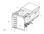
- the upper container opening 4, which forms the filling opening, is covered by the covering device 6 formed by the two cover elements 5, such as Fig. 1 shows.
- the material located in the reservoir 2 is protected against the effects of weather, such as rain, etc.
- the covering device 6 is divided in the middle into two cover elements which form cover elements 5.
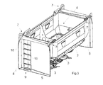
- Each cover 5 is by means of a hinge device 7, such as Fig. 2 and 3 show attached to the reservoir 2 and each to bring laterally next to the reservoir 2 in an upright position, as the Fig. 2 and 3 demonstrate.
- each cover element 5 ascent stages 8 On the inside of each cover element 5 ascent stages 8 a rise device 9 are arranged. There are several ascent stages 8 arranged in ladder form one above the other. On the side of the ascent stages 8, in each case a hand element 10, which is formed by the upright elements of the conductor element, is arranged on the covering device 6. The ascent stages 8 are arranged on the inside of the cover 6, as the Fig. 2 and 3 demonstrate.
- the covering device 6 is provided with the ascending steps 8 from the position covering the container opening 4, as in FIG Fig. 1 and 2 shown in which the container opening 4 is covered to bring in an upright rise position for the access device 9. After filling the storage container 2, the cover elements 5 of the cover 6 from the in the Fig. 2 and 3 Positions shown in the Fig. 1 and 2 shown to bring positions in which the cover 5, the container opening 4 again.
- the embodiment of the distributor according to Fig. 4 differs from the distributor according to the Fig. 1 to 3 in that the exit steps 11 of the ascent device 12 with the hand holding elements 13 are arranged on the outside of the cover elements 14 of the covering device 15.
- This cover 15 is how the Fig. 4 shows, formed as a molded part, wherein in the molded part, the ascent stages 11 are formed in a molded manner.
- the ascent stages 11 extend over the entire seen in the direction of travel 16 depth of the cover elements 14, so that when rain, the rainwater as in a roof over the obliquely downwardly extending downward surfaces 17 run to the outside can. It is also possible to attach further hand holding elements 13 to each cover element 14.
- the cover elements 14 according to the embodiment according to Fig. 4 are attached by means of a multi-linkage 18 to the reservoir 2 to bring the desired folding movement of the lid members 14 from the container opening 4 covering position in the rise position for the riser element 12 when the lid members 14 are located laterally next to the reservoir 2.
- the cover elements 14 of the on the Multi-joint linkage 18 attacking motor actuator 19, for example, a hydraulic cylinder or electric drive can be pivoted.
Landscapes
- Life Sciences & Earth Sciences (AREA)
- Soil Sciences (AREA)
- Environmental Sciences (AREA)
- Fertilizing (AREA)
Abstract
Description
- Die Erfindung betrifft eine landwirtschaftliche Verteilmaschine gemäß des Oberbegriffes des Patentanspruches 1.
- Eine derartige landwirtschaftliche Verteilmaschine wird beispielsweise durch die
EP 1 849 345 B1 bekannt. Diese landwirtschaftliche Verteilmaschine ist als Zentrifugaldüngerstreuer ausgebildet und weist einen Rahmen und Vorratsbehälter mit zumindest einer oberen als Befülleinrichtung dienen Behälteröffnung auf. In den seitlichen, die Maschine verkleidende Wänden sind mehrere Aufstiegsstufen einer Aufstiegseinrichtung angeordnet. Eine derartige Anordnung lässt sich nur verwirklichen, wenn die Verteilmaschine zusätzliche seitliche Wände aufweist. - Durch die
EP 1 504 644 B1 ist eine weitere als Zentrifugaldüngerstreuer ausgebildete Verteilmaschine bekannt geworden. Diese Verteilmaschine weist einen Vorratsbehälter mit einem Schutzbügel auf. Ein Teil des Schutzbügels wird von einem in eine liegende Position bringbaren Leiterelement gebildet, welches zum Befüllen der Maschine in eine aufrechte Aufstiegsposition bringbar ist. - Hier ist es erforderlich, dass das Leiterelement jeweils in einen separaten Arbeitsgang umstellt werden muss.
- Der Erfindung liegt die Aufgabe zugrunde, eine einfachere Ausgestaltung eines Leiterelementes zu schaffen, welches einfach in seine Aufstiegsposition bringbar ist.
- Diese Aufgabe wird erfindungsgemäß dadurch gelöst, dass dem Vorratsbehälter zumindest eine Abdeckvorrichtung zur Abdeckung der Behälteröffnung zugeordnet ist, dass an der Abdeckeinrichtung mehrere Aufstiegsstufen der Aufstiegsvorrichtung angeordnet sind, dass die Abdeckvorrichtung mit den Aufstiegsstufen aus der die Behälteröffnung deckenden Position in eine aufrechte Aufstiegsposition für die Aufstiegsvorrichtung und umgekehrt bringbar ist. Infolge dieser Maßnahmen wird durch das Öffnen der Behälteröffnung durch Verbringen der Abdeckvorrichtung aus der Abdeckposition in die Befüllposition automatisch die Aufstiegsvorrichtung in die Aufstiegsposition gebracht. Es lässt sich diese Aufstiegsvorrichtung bei allen Verteilmaschinen verwirklichen, welche mit einer Abdeckvorrichtung für die Behälteröffnung erforderlich ist und bei denen die Abdeckvorrichtung der Position des Abdeckens der Behälteröffnung zum Befüllen des Vorratsbehälters in eine die Behälteröffnung freigebende Position gebracht werden muss. Somit wird also durch das Verbringen der Abdeckvorrichtung aus der Abdeckposition in die Befüllposition automatisch die Aufstiegsvorrichtung in die Aufstiegsposition verbracht.
- In einfacher Weise lässt sich die Aufstiegsvorrichtung in die Abdeckvorrichtung dadurch integrieren, dass die Abdeckeinrichtung als Formteil ausgebildet ist, dass in dem Formteil die Aufstiegsstufen eingeformt ausgebildet sind.
- Um einen sicheren Aufstieg auf der Aufstiegsvorrichtung entsprechend den Sicherheitsnormen und -vorschriften zu gewährleisten, ist vorgesehen, dass neben den Aufstiegsstufen an der Abdeckeinrichtung zumindest ein Handhalteelement angeordnet ist.
- In einer Ausgestaltung ist vorgesehen, dass die Aufstiegsstufen auf der Außenseite der Abdeckvorrichtung angeordnet sind.
- In einer anderen Ausgestaltung ist vorgesehen, dass die Aufstiegsstufen auf der Innenseite der Abdeckvorrichtung angeordnet sind.
- Eine einfache Anordnung und Verbringen der Abdeckvorrichtung in die jeweilige Position lässt sich dadurch erreichen, dass die Abdeckvorrichtung mittels zumindest einer Gelenkvorrichtung am Vorratsbehälter befestigt ist
- Auch ist es möglich, um die Abdeckvorrichtung mit der Aufstiegsvorrichtung in die jeweils gewünschte Position zu verbringen, dass die Abdeckvorrichtung mittels eines Mehrgelenkgestänges an dem Vorratsbehälter befestigt ist.
- Bei Vorratsbehältern mit großen Befüllöffnungen, die durch entsprechend große Abdeckvorrichtungen abgedeckt werden müssen, ist vorgesehen, dass die Abdeckeinrichtung aus zwei zumindest annähernd in der Mitte der Abdeckeinrichtung geteilten Abdeckelementen besteht, wobei jeweils ein Abdeckelement zu einer Seite seitlich neben dem Vorratsbehälter in eine aufrechte Stellung bringbar ist.
- Auch ist es möglich, die Abdeckvorrichtung in eine aufrechte Position hinter oder vor dem Vorratsbehälter zu verbringen.
- Weitere Einzelheiten der Erfindung sind der
Beispielsbeschreibung und den Zeichnungen zu entnehmen. Hierbei zeigen - Fig. 1
- die als Zentrifugaldüngerstreuer ausgebildete Verteilmaschine mit den sich in Abdeckposition befindlichen als Deckelelemente ausgebildeten Abdeckelementen in perspektivischer Ansicht,
- Fig. 2
- die Verteilmaschine gemäß
Fig. 1 , wobei die in Fahrtrichtung gesehen linke Hälfte der Abdeckeinrichtung in die die Befüllöffnung freigegebende Position geklappt ist, - Fig. 3
- die Verteilmaschine gemäß
Fig. 1 , wobei beide Hälften der Abdeckeinrichtung in die die Befüllöffnung freigegebenden Positionen geklappt sind und - Fig. 4
- eine weitere Verteilmaschine in perspektivischer Darstellung, wobei das in Fahrtrichtung gesehen linke Deckelelement in die die Behälteröffnung freigegebende Position geklappt ist.
- Die als Schleuderdüngerstreuer ausgebildete Verteilmaschine gemäß den
Fig. 1 bis 3 weist einen mit einem Rahmen 1 ausgestatteten Vorratsbehälter 2 auf. Der Vorratsbehälter weist zwei Auslauftrichter auf, die durch Dosierelemente abgeschlossen sind. Unterhalb der Dosierelemente sind rotierend angeordnete Schleuderscheiben 3 angeordnet. Der Vorratsbehälter 2 weist eine obere Behälteröffnung 4 auf, über welche der Vorratsbehälter 2 mit dem auszubringenden Material befüllt wird. Die obere Behälteröffnung 4, die Befüllöffnung bildet, wird über die von den beiden Deckelelementen 5 gebildete Abdeckeinrichtung 6 abgedeckt, wieFig. 1 zeigt. Hierdurch ist das sich in dem Vorratsbehälter 2 befindliche Material gegen Witterungseinflüsse, wie Regen etc. geschützt. - Die Abdeckeinrichtung 6 ist in der Mitte in zwei Abdeckelemente, die Deckelelemente 5 bilden, geteilt. Jedes Abdeckelement 5 ist mittels einer Gelenkvorrichtung 7, wie
Fig. 2 und3 zeigen an dem Vorratsbehälter 2 befestigt und jeweils seitlich neben dem Vorratsbehälter 2 in eine aufrechte Stellung zu bringen, wie dieFig. 2 und3 zeigen. - Auf der Innenseite jedes Deckelelementes 5 sind Aufstiegsstufen 8 einer Aufstiegsvorrichtung 9 angeordnet. Es sind mehrere Aufstiegsstufen 8 in Leiterform übereinander angeordnet. Seitlich neben den Aufstiegsstufen 8 ist an der Abdeckeinrichtung 6 jeweils ein Handelement 10 angeordnet, welches von den aufrechten Elementen des Leiterelementes gebildet wird. Die Aufstiegsstufen 8 sind auf der Innenseite der Abdeckeinrichtung 6 angeordnet, wie die
Fig. 2 und3 zeigen. Die Abdeckeinrichtung 6 ist mit den Aufstiegesstufen 8 aus der die Behälteröffnung 4 abdeckenden Position, wie inFig. 1 und2 gezeigt, in welcher die Behälteröffnung 4 abgedeckt wird, in eine aufrechte Aufstiegsposition für die Aufstiegseinrichtung 9 zu bringen. Nach dem Befüllen des Vorratsbehälters 2 sind die Deckelelemente 5 der Abdeckeinrichtung 6 aus den in denFig. 2 und3 gezeigten Positionen in die inFig. 1 und2 gezeigten Positionen zu bringen, in welcher die Abdeckelemente 5 die Behälteröffnung 4 wieder abdecken. - Die Ausgestaltung der Verteilmaschine gemäß
Fig. 4 unterscheidet sich von der Verteilmaschine gemäß denFig. 1 bis 3 dadurch, dass die Ausstiegsstufen 11 der Aufstiegsvorrichtung 12 mit den Handhaltelementen 13 auf der Außenseite der Deckelemente 14 der Abdeckvorrichtung 15 angeordnet sind. Diese Abdeckeinrichtung 15 ist, wie dieFig. 4 zeigt, als Formteil ausgebildet, wobei in dem Formteil die Aufstiegsstufen 11 in eingeformter Weise ausgebildet sind. Hierbei verlaufen die Aufstiegsstufen 11 über die gesamte in Fahrtrichtung 16 gesehene Tiefe der Deckelelemente 14 , damit bei Regen das Regenwasser wie bei einem Dach über die schräg nach hinten unten verlaufenden Flächen 17 nach außen ablaufen kann. Es ist auch noch möglich, weitere Handhalteelemente 13 an jedem Deckelelement 14 anzubringen. - Die Deckelelemente 14 gemäß dem Ausführungsbeispiel nach
Fig. 4 sind mittels eines Mehrgelenkgestänges 18 an dem Vorratsbehälter 2 befestigt, um die gewünschte Klappbewegung der Deckelelemente 14 aus der die Behälteröffnung 4 abdeckenden Position in die Aufstiegsposition für das Aufstiegselement 12, wenn die Deckelelemente 14 seitlich neben dem Vorratsbehälter 2 befinden zu bringen. Hierbei können die Deckelelemente 14 von dem an dem
Mehrgelenkgestänge 18 angreifenden motorischen Stellelement 19, beispielsweise einem Hydraulikzylinder oder Elektroantrieb, verschwenkt werden. - An Stelle die Abdeckelemente 5, 14 bzw. die Abdeckvorrichtung seitlich neben dem Vorratsbehälter 2 zu verschwenken, ist es selbstverständlich auch möglich, wenn die Maschine entsprechend ausgestaltet ist, die Abdeckeinrichtung 5, 14 mit den Aufstiegseinrichtungen 9, 12 in eine aufrechte Position vor oder hinter dem Vorratsbehälter 2 zu bringen.
Claims (10)
- Landwirtschaftliche Verteilmaschine zum Ausbringen von insbesondere körnigen Materialien mit einem Rahmen, Vorratsbehälter mit zumindest einer oberen als Befüllöffnung dienenden Behälteröffnung, zugeordneten Dosiervorrichtungen, Materialausbringelementen und zumindest einer mehrere Aufstiegsstufen ausweisenden Aufstiegsvorrichtung, dadurch gekennzeichnet, dass dem Vorratsbehälter (2) zumindest eine Abdeckvorrichtung (5, 6, 14, 15) zur Abdeckung der Behälteröffnung (4)zugeordnet ist, dass an der Abdeckeinrichtung (5, 6, 14, 15) mehrere Aufstiegsstufen (8, 11) der Aufstiegsvorrichtung (9, 12) angeordnet sind, dass die Abdeckvorrichtung (5, 6, 14, 15) mit den Aufstiegsstufen (8, 11) aus der die Behälteröffnung (4) abdeckenden Position in eine aufrechte Aufstiegsposition für die Aufstiegsvorrichtung (9, 12) und umgekehrt bringbar ist.
- Verteilmaschine nach Anspruch 1, dadurch gekennzeichnet, dass die Abdeckeinrichtung (14) als Formteil ausgebildet ist, dass in dem Formteil die Aufstiegsstufen (11) eingeformt ausgebildet sind.
- Verteilmaschine nach zumindest einem der vorstehenden Ansprüche, dadurch gekennzeichnet, dass neben den Aufstiegsstufen (8, 11) an der Abdeckeinrichtung (5, 6, 14, 15) zumindest ein Handhalteelement (10, 13) angeordnet ist.
- Verteilmaschine nach zumindest einem der vorstehenden Ansprüche, dadurch gekennzeichnet, dass die Aufstiegsstufen (11) auf der Außenseite der Abdeckvorrichtung (14, 15) angeordnet sind.
- Verteilmaschine nach zumindest einem der vorstehenden Ansprüche, dadurch gekennzeichnet, dass die Aufstiegsstufen (8) auf der Innenseite der Abdeckvorrichtung (5,6) angeordnet sind.
- Verteilmaschine nach zumindest einem der vorstehenden Ansprüche, dadurch gekennzeichnet, dass die Abdeckvorrichtung (5, 6, 14, 15) mittels zumindest einer Gelenkvorrichtung (7, 18) am Vorratsbehälter (2) befestigt ist.
- Verteilmaschine nach zumindest einem der vorstehenden Ansprüche, dadurch gekennzeichnet, dass die Abdeckvorrichtung (14, 15) mittels eines Mehrgelenkgestänges (18) an dem Vorratsbehälter (2) befestigt ist.
- Verteilmaschine nach zumindest einem der vorstehenden Ansprüche, dadurch gekennzeichnet, dass die Abdeckeinrichtung (5, 6, 14, 15) aus zwei zumindest annähernd in der Mitte der Abdeckeinrichtung (6, 15) geteilten Abdeckelementen (5, 14) besteht, wobei jeweils ein Abdeckelement (5, 14) zu einer Seite seitlich neben dem Vorratsbehälter (2) in eine aufrechte Stellung bringbar ist.
- Verteilmaschine nach Anspruch 1, dadurch gekennzeichnet, dass die Abdeckeinrichtung (6, 15) in eine aufrechte Position in Fahrtrichtung gesehen hinter dem Vorratsbehälter (2) bringbar ist.
- Verteilmaschine nach Anspruch 1, dadurch gekennzeichnet, dass die Abdeckeinrichtung (6, 15) in eine aufrechte Position in Fahrtrichtung gesehen vor dem Vorratsbehälter (2) bringbar ist.
Applications Claiming Priority (1)
| Application Number | Priority Date | Filing Date | Title |
|---|---|---|---|
| DE201010015863 DE102010015863A1 (de) | 2010-03-09 | 2010-03-09 | Landwirtschaftliche Verteilmaschine |
Publications (2)
| Publication Number | Publication Date |
|---|---|
| EP2364583A1 true EP2364583A1 (de) | 2011-09-14 |
| EP2364583B1 EP2364583B1 (de) | 2013-12-25 |
Family
ID=44118504
Family Applications (1)
| Application Number | Title | Priority Date | Filing Date |
|---|---|---|---|
| EP20110401034 Not-in-force EP2364583B1 (de) | 2010-03-09 | 2011-02-28 | Landwirtschaftliche Verteilmaschine |
Country Status (2)
| Country | Link |
|---|---|
| EP (1) | EP2364583B1 (de) |
| DE (1) | DE102010015863A1 (de) |
Cited By (1)
| Publication number | Priority date | Publication date | Assignee | Title |
|---|---|---|---|---|
| EP2586348A1 (de) | 2011-10-27 | 2013-05-01 | Achton A/S | Ausgabe mit Bremsmechanismus für eine Papierrolle |
Citations (5)
| Publication number | Priority date | Publication date | Assignee | Title |
|---|---|---|---|---|
| EP1504644B1 (de) | 2003-08-05 | 2007-03-21 | Amazonen-Werke H. Dreyer GmbH & Co. KG | Schleuderdüngerstreuer |
| EP1849345A1 (de) * | 2006-04-26 | 2007-10-31 | Amazonen-Werke H. Dreyer GmbH & Co. KG | Vorrichtung zum Streuen körniger Stoffe |
| US7467591B1 (en) * | 2007-08-29 | 2008-12-23 | Cnh America, Llc | Planter with retractable access |
| DE202008013948U1 (de) * | 2008-10-18 | 2009-01-08 | Rauch Landmaschinenfabrik Gmbh | Landmaschine, insbesondere Verteilmaschine |
| EP2232975A1 (de) * | 2009-03-18 | 2010-09-29 | Amazonen-Werke H. Dreyer GmbH & Co. KG | Vorratsbehältereinheit |
-
2010
- 2010-03-09 DE DE201010015863 patent/DE102010015863A1/de not_active Withdrawn
-
2011
- 2011-02-28 EP EP20110401034 patent/EP2364583B1/de not_active Not-in-force
Patent Citations (6)
| Publication number | Priority date | Publication date | Assignee | Title |
|---|---|---|---|---|
| EP1504644B1 (de) | 2003-08-05 | 2007-03-21 | Amazonen-Werke H. Dreyer GmbH & Co. KG | Schleuderdüngerstreuer |
| EP1849345A1 (de) * | 2006-04-26 | 2007-10-31 | Amazonen-Werke H. Dreyer GmbH & Co. KG | Vorrichtung zum Streuen körniger Stoffe |
| EP1849345B1 (de) | 2006-04-26 | 2009-06-17 | Amazonen-Werke H. Dreyer GmbH & Co. KG | Vorrichtung zum Streuen körniger Stoffe |
| US7467591B1 (en) * | 2007-08-29 | 2008-12-23 | Cnh America, Llc | Planter with retractable access |
| DE202008013948U1 (de) * | 2008-10-18 | 2009-01-08 | Rauch Landmaschinenfabrik Gmbh | Landmaschine, insbesondere Verteilmaschine |
| EP2232975A1 (de) * | 2009-03-18 | 2010-09-29 | Amazonen-Werke H. Dreyer GmbH & Co. KG | Vorratsbehältereinheit |
Cited By (1)
| Publication number | Priority date | Publication date | Assignee | Title |
|---|---|---|---|---|
| EP2586348A1 (de) | 2011-10-27 | 2013-05-01 | Achton A/S | Ausgabe mit Bremsmechanismus für eine Papierrolle |
Also Published As
| Publication number | Publication date |
|---|---|
| DE102010015863A1 (de) | 2011-09-15 |
| EP2364583B1 (de) | 2013-12-25 |
Similar Documents
| Publication | Publication Date | Title |
|---|---|---|
| DE2603468C3 (de) | Vorrichtung zum Füllen von Filterzellen mit körnigem, insbesondere schwerbeweglichem Adsorberstoff | |
| EP2832202B1 (de) | Sämaschine | |
| EP1570716A2 (de) | Landwirtschaftliche Dossiervorrichtung | |
| DE202008013948U1 (de) | Landmaschine, insbesondere Verteilmaschine | |
| EP2364583B1 (de) | Landwirtschaftliche Verteilmaschine | |
| EP2807915A1 (de) | Landwirtschaftliche Verteilmaschine | |
| EP3262913B1 (de) | Landwirtschaftliche verteilmaschine mit bedienzentrum | |
| EP3124194A1 (de) | Mischmaschine, insbesondere baumischmaschine, zum mischen von mischgut, insbesondere zum mischen von mörteln, putzen, estrichen oder beton und verfahren zur bedienung einer solchen mischmaschine | |
| EP2353359B1 (de) | Landwirtschaftliche Vorrichtung | |
| EP2777375A1 (de) | Kombinierte landwirtschaftliche Verteilmaschine | |
| DE3000719A1 (de) | Fuetterungsvorrichtung insbesondere fuer schweine | |
| EP3979781B1 (de) | Pneumatische saatgut- und/oder duengerverteilmaschine | |
| EP2353360A1 (de) | Zentrifugalstreuer | |
| EP3666052B1 (de) | Tankbehälter für eine sämaschine und sämaschine | |
| DE102010000298A1 (de) | Zweischeibenstreuer | |
| EP2353358B1 (de) | Landwirtschaftliche Vorrichtung | |
| EP3143858B1 (de) | Gezogene verteilmaschine | |
| DE102009043843A1 (de) | Träger aus Karton od. dgl. | |
| EP2687076B1 (de) | Landwirtschaftliche verteilmaschine | |
| DE102008022646A1 (de) | Scheibenstreuer | |
| EP2574224A1 (de) | Siebartige Abdeck- und Schutzeinrichtung | |
| DE8014879U1 (de) | Vorrats- und Abfuellbehaelter | |
| DE19749229A1 (de) | Verteilmaschine | |
| DE202008016014U1 (de) | Tragevorrichtung | |
| DE19906428A1 (de) | Schleuderdüngerstreuer |
Legal Events
| Date | Code | Title | Description |
|---|---|---|---|
| PUAI | Public reference made under article 153(3) epc to a published international application that has entered the european phase |
Free format text: ORIGINAL CODE: 0009012 |
|
| AK | Designated contracting states |
Kind code of ref document: A1 Designated state(s): AL AT BE BG CH CY CZ DE DK EE ES FI FR GB GR HR HU IE IS IT LI LT LU LV MC MK MT NL NO PL PT RO RS SE SI SK SM TR |
|
| AX | Request for extension of the european patent |
Extension state: BA ME |
|
| 17P | Request for examination filed |
Effective date: 20120302 |
|
| GRAP | Despatch of communication of intention to grant a patent |
Free format text: ORIGINAL CODE: EPIDOSNIGR1 |
|
| RIC1 | Information provided on ipc code assigned before grant |
Ipc: A01C 17/00 20060101ALI20130906BHEP Ipc: A01C 15/00 20060101AFI20130906BHEP |
|
| INTG | Intention to grant announced |
Effective date: 20131007 |
|
| GRAS | Grant fee paid |
Free format text: ORIGINAL CODE: EPIDOSNIGR3 |
|
| GRAA | (expected) grant |
Free format text: ORIGINAL CODE: 0009210 |
|
| AK | Designated contracting states |
Kind code of ref document: B1 Designated state(s): AL AT BE BG CH CY CZ DE DK EE ES FI FR GB GR HR HU IE IS IT LI LT LU LV MC MK MT NL NO PL PT RO RS SE SI SK SM TR |
|
| REG | Reference to a national code |
Ref country code: GB Ref legal event code: FG4D Free format text: NOT ENGLISH |
|
| REG | Reference to a national code |
Ref country code: CH Ref legal event code: EP |
|
| REG | Reference to a national code |
Ref country code: AT Ref legal event code: REF Ref document number: 646071 Country of ref document: AT Kind code of ref document: T Effective date: 20140115 |
|
| REG | Reference to a national code |
Ref country code: IE Ref legal event code: FG4D Free format text: LANGUAGE OF EP DOCUMENT: GERMAN |
|
| REG | Reference to a national code |
Ref country code: DE Ref legal event code: R096 Ref document number: 502011001876 Country of ref document: DE Effective date: 20140213 |
|
| PG25 | Lapsed in a contracting state [announced via postgrant information from national office to epo] |
Ref country code: FI Free format text: LAPSE BECAUSE OF FAILURE TO SUBMIT A TRANSLATION OF THE DESCRIPTION OR TO PAY THE FEE WITHIN THE PRESCRIBED TIME-LIMIT Effective date: 20131225 Ref country code: SE Free format text: LAPSE BECAUSE OF FAILURE TO SUBMIT A TRANSLATION OF THE DESCRIPTION OR TO PAY THE FEE WITHIN THE PRESCRIBED TIME-LIMIT Effective date: 20131225 Ref country code: LT Free format text: LAPSE BECAUSE OF FAILURE TO SUBMIT A TRANSLATION OF THE DESCRIPTION OR TO PAY THE FEE WITHIN THE PRESCRIBED TIME-LIMIT Effective date: 20131225 Ref country code: HR Free format text: LAPSE BECAUSE OF FAILURE TO SUBMIT A TRANSLATION OF THE DESCRIPTION OR TO PAY THE FEE WITHIN THE PRESCRIBED TIME-LIMIT Effective date: 20131225 Ref country code: NO Free format text: LAPSE BECAUSE OF FAILURE TO SUBMIT A TRANSLATION OF THE DESCRIPTION OR TO PAY THE FEE WITHIN THE PRESCRIBED TIME-LIMIT Effective date: 20140325 |
|
| REG | Reference to a national code |
Ref country code: NL Ref legal event code: VDEP Effective date: 20131225 |
|
| REG | Reference to a national code |
Ref country code: LT Ref legal event code: MG4D |
|
| PG25 | Lapsed in a contracting state [announced via postgrant information from national office to epo] |
Ref country code: RS Free format text: LAPSE BECAUSE OF FAILURE TO SUBMIT A TRANSLATION OF THE DESCRIPTION OR TO PAY THE FEE WITHIN THE PRESCRIBED TIME-LIMIT Effective date: 20131225 Ref country code: LV Free format text: LAPSE BECAUSE OF FAILURE TO SUBMIT A TRANSLATION OF THE DESCRIPTION OR TO PAY THE FEE WITHIN THE PRESCRIBED TIME-LIMIT Effective date: 20131225 |
|
| PG25 | Lapsed in a contracting state [announced via postgrant information from national office to epo] |
Ref country code: EE Free format text: LAPSE BECAUSE OF FAILURE TO SUBMIT A TRANSLATION OF THE DESCRIPTION OR TO PAY THE FEE WITHIN THE PRESCRIBED TIME-LIMIT Effective date: 20131225 Ref country code: IS Free format text: LAPSE BECAUSE OF FAILURE TO SUBMIT A TRANSLATION OF THE DESCRIPTION OR TO PAY THE FEE WITHIN THE PRESCRIBED TIME-LIMIT Effective date: 20140425 |
|
| PG25 | Lapsed in a contracting state [announced via postgrant information from national office to epo] |
Ref country code: NL Free format text: LAPSE BECAUSE OF FAILURE TO SUBMIT A TRANSLATION OF THE DESCRIPTION OR TO PAY THE FEE WITHIN THE PRESCRIBED TIME-LIMIT Effective date: 20131225 Ref country code: CZ Free format text: LAPSE BECAUSE OF FAILURE TO SUBMIT A TRANSLATION OF THE DESCRIPTION OR TO PAY THE FEE WITHIN THE PRESCRIBED TIME-LIMIT Effective date: 20131225 Ref country code: ES Free format text: LAPSE BECAUSE OF FAILURE TO SUBMIT A TRANSLATION OF THE DESCRIPTION OR TO PAY THE FEE WITHIN THE PRESCRIBED TIME-LIMIT Effective date: 20131225 Ref country code: RO Free format text: LAPSE BECAUSE OF FAILURE TO SUBMIT A TRANSLATION OF THE DESCRIPTION OR TO PAY THE FEE WITHIN THE PRESCRIBED TIME-LIMIT Effective date: 20131225 Ref country code: PT Free format text: LAPSE BECAUSE OF FAILURE TO SUBMIT A TRANSLATION OF THE DESCRIPTION OR TO PAY THE FEE WITHIN THE PRESCRIBED TIME-LIMIT Effective date: 20140428 Ref country code: SK Free format text: LAPSE BECAUSE OF FAILURE TO SUBMIT A TRANSLATION OF THE DESCRIPTION OR TO PAY THE FEE WITHIN THE PRESCRIBED TIME-LIMIT Effective date: 20131225 Ref country code: CY Free format text: LAPSE BECAUSE OF FAILURE TO SUBMIT A TRANSLATION OF THE DESCRIPTION OR TO PAY THE FEE WITHIN THE PRESCRIBED TIME-LIMIT Effective date: 20131225 |
|
| BERE | Be: lapsed |
Owner name: AMAZONEN-WERKE H. DREYER G.M.B.H. & CO. KG Effective date: 20140228 |
|
| REG | Reference to a national code |
Ref country code: DE Ref legal event code: R097 Ref document number: 502011001876 Country of ref document: DE |
|
| PG25 | Lapsed in a contracting state [announced via postgrant information from national office to epo] |
Ref country code: MC Free format text: LAPSE BECAUSE OF FAILURE TO SUBMIT A TRANSLATION OF THE DESCRIPTION OR TO PAY THE FEE WITHIN THE PRESCRIBED TIME-LIMIT Effective date: 20131225 Ref country code: LU Free format text: LAPSE BECAUSE OF FAILURE TO SUBMIT A TRANSLATION OF THE DESCRIPTION OR TO PAY THE FEE WITHIN THE PRESCRIBED TIME-LIMIT Effective date: 20140228 |
|
| REG | Reference to a national code |
Ref country code: CH Ref legal event code: PL |
|
| PG25 | Lapsed in a contracting state [announced via postgrant information from national office to epo] |
Ref country code: LI Free format text: LAPSE BECAUSE OF NON-PAYMENT OF DUE FEES Effective date: 20140228 Ref country code: CH Free format text: LAPSE BECAUSE OF NON-PAYMENT OF DUE FEES Effective date: 20140228 Ref country code: DK Free format text: LAPSE BECAUSE OF FAILURE TO SUBMIT A TRANSLATION OF THE DESCRIPTION OR TO PAY THE FEE WITHIN THE PRESCRIBED TIME-LIMIT Effective date: 20131225 |
|
| PLBE | No opposition filed within time limit |
Free format text: ORIGINAL CODE: 0009261 |
|
| STAA | Information on the status of an ep patent application or granted ep patent |
Free format text: STATUS: NO OPPOSITION FILED WITHIN TIME LIMIT |
|
| PG25 | Lapsed in a contracting state [announced via postgrant information from national office to epo] |
Ref country code: PL Free format text: LAPSE BECAUSE OF FAILURE TO SUBMIT A TRANSLATION OF THE DESCRIPTION OR TO PAY THE FEE WITHIN THE PRESCRIBED TIME-LIMIT Effective date: 20131225 |
|
| 26N | No opposition filed |
Effective date: 20140926 |
|
| REG | Reference to a national code |
Ref country code: IE Ref legal event code: MM4A |
|
| REG | Reference to a national code |
Ref country code: DE Ref legal event code: R097 Ref document number: 502011001876 Country of ref document: DE Effective date: 20140926 |
|
| PG25 | Lapsed in a contracting state [announced via postgrant information from national office to epo] |
Ref country code: IE Free format text: LAPSE BECAUSE OF NON-PAYMENT OF DUE FEES Effective date: 20140228 Ref country code: BE Free format text: LAPSE BECAUSE OF NON-PAYMENT OF DUE FEES Effective date: 20140228 |
|
| PG25 | Lapsed in a contracting state [announced via postgrant information from national office to epo] |
Ref country code: SI Free format text: LAPSE BECAUSE OF FAILURE TO SUBMIT A TRANSLATION OF THE DESCRIPTION OR TO PAY THE FEE WITHIN THE PRESCRIBED TIME-LIMIT Effective date: 20131225 |
|
| GBPC | Gb: european patent ceased through non-payment of renewal fee |
Effective date: 20150228 |
|
| REG | Reference to a national code |
Ref country code: FR Ref legal event code: PLFP Year of fee payment: 6 |
|
| PG25 | Lapsed in a contracting state [announced via postgrant information from national office to epo] |
Ref country code: GB Free format text: LAPSE BECAUSE OF NON-PAYMENT OF DUE FEES Effective date: 20150228 |
|
| PG25 | Lapsed in a contracting state [announced via postgrant information from national office to epo] |
Ref country code: MT Free format text: LAPSE BECAUSE OF FAILURE TO SUBMIT A TRANSLATION OF THE DESCRIPTION OR TO PAY THE FEE WITHIN THE PRESCRIBED TIME-LIMIT Effective date: 20131225 |
|
| PG25 | Lapsed in a contracting state [announced via postgrant information from national office to epo] |
Ref country code: SM Free format text: LAPSE BECAUSE OF FAILURE TO SUBMIT A TRANSLATION OF THE DESCRIPTION OR TO PAY THE FEE WITHIN THE PRESCRIBED TIME-LIMIT Effective date: 20131225 |
|
| PG25 | Lapsed in a contracting state [announced via postgrant information from national office to epo] |
Ref country code: BG Free format text: LAPSE BECAUSE OF FAILURE TO SUBMIT A TRANSLATION OF THE DESCRIPTION OR TO PAY THE FEE WITHIN THE PRESCRIBED TIME-LIMIT Effective date: 20131225 Ref country code: GR Free format text: LAPSE BECAUSE OF FAILURE TO SUBMIT A TRANSLATION OF THE DESCRIPTION OR TO PAY THE FEE WITHIN THE PRESCRIBED TIME-LIMIT Effective date: 20140326 |
|
| PG25 | Lapsed in a contracting state [announced via postgrant information from national office to epo] |
Ref country code: TR Free format text: LAPSE BECAUSE OF FAILURE TO SUBMIT A TRANSLATION OF THE DESCRIPTION OR TO PAY THE FEE WITHIN THE PRESCRIBED TIME-LIMIT Effective date: 20131225 Ref country code: HU Free format text: LAPSE BECAUSE OF FAILURE TO SUBMIT A TRANSLATION OF THE DESCRIPTION OR TO PAY THE FEE WITHIN THE PRESCRIBED TIME-LIMIT; INVALID AB INITIO Effective date: 20110228 |
|
| REG | Reference to a national code |
Ref country code: FR Ref legal event code: PLFP Year of fee payment: 7 |
|
| REG | Reference to a national code |
Ref country code: AT Ref legal event code: MM01 Ref document number: 646071 Country of ref document: AT Kind code of ref document: T Effective date: 20160228 |
|
| PG25 | Lapsed in a contracting state [announced via postgrant information from national office to epo] |
Ref country code: AT Free format text: LAPSE BECAUSE OF NON-PAYMENT OF DUE FEES Effective date: 20160228 |
|
| REG | Reference to a national code |
Ref country code: FR Ref legal event code: PLFP Year of fee payment: 8 |
|
| PGFP | Annual fee paid to national office [announced via postgrant information from national office to epo] |
Ref country code: DE Payment date: 20180214 Year of fee payment: 8 |
|
| PGFP | Annual fee paid to national office [announced via postgrant information from national office to epo] |
Ref country code: FR Payment date: 20180111 Year of fee payment: 8 Ref country code: IT Payment date: 20180221 Year of fee payment: 8 |
|
| PG25 | Lapsed in a contracting state [announced via postgrant information from national office to epo] |
Ref country code: MK Free format text: LAPSE BECAUSE OF FAILURE TO SUBMIT A TRANSLATION OF THE DESCRIPTION OR TO PAY THE FEE WITHIN THE PRESCRIBED TIME-LIMIT Effective date: 20131225 |
|
| PG25 | Lapsed in a contracting state [announced via postgrant information from national office to epo] |
Ref country code: AL Free format text: LAPSE BECAUSE OF FAILURE TO SUBMIT A TRANSLATION OF THE DESCRIPTION OR TO PAY THE FEE WITHIN THE PRESCRIBED TIME-LIMIT Effective date: 20131225 |
|
| REG | Reference to a national code |
Ref country code: DE Ref legal event code: R119 Ref document number: 502011001876 Country of ref document: DE |
|
| PG25 | Lapsed in a contracting state [announced via postgrant information from national office to epo] |
Ref country code: DE Free format text: LAPSE BECAUSE OF NON-PAYMENT OF DUE FEES Effective date: 20190903 |
|
| PG25 | Lapsed in a contracting state [announced via postgrant information from national office to epo] |
Ref country code: FR Free format text: LAPSE BECAUSE OF NON-PAYMENT OF DUE FEES Effective date: 20190228 Ref country code: IT Free format text: LAPSE BECAUSE OF NON-PAYMENT OF DUE FEES Effective date: 20190228 |