EP2364070A2 - Electrode with cooling pipe for a plasma cutting device - Google Patents
Electrode with cooling pipe for a plasma cutting device Download PDFInfo
- Publication number
- EP2364070A2 EP2364070A2 EP10015592A EP10015592A EP2364070A2 EP 2364070 A2 EP2364070 A2 EP 2364070A2 EP 10015592 A EP10015592 A EP 10015592A EP 10015592 A EP10015592 A EP 10015592A EP 2364070 A2 EP2364070 A2 EP 2364070A2
- Authority
- EP
- European Patent Office
- Prior art keywords
- electrode body
- stop
- electrode
- recess
- cooling tube
- Prior art date
- Legal status (The legal status is an assumption and is not a legal conclusion. Google has not performed a legal analysis and makes no representation as to the accuracy of the status listed.)
- Granted
Links
Images


Classifications
-
- H—ELECTRICITY
- H05—ELECTRIC TECHNIQUES NOT OTHERWISE PROVIDED FOR
- H05H—PLASMA TECHNIQUE; PRODUCTION OF ACCELERATED ELECTRICALLY-CHARGED PARTICLES OR OF NEUTRONS; PRODUCTION OR ACCELERATION OF NEUTRAL MOLECULAR OR ATOMIC BEAMS
- H05H1/00—Generating plasma; Handling plasma
- H05H1/24—Generating plasma
- H05H1/26—Plasma torches
- H05H1/32—Plasma torches using an arc
- H05H1/34—Details, e.g. electrodes, nozzles
- H05H1/3436—Hollow cathodes with internal coolant flow
Definitions
- the invention relates to a spacer for the cooling tube of an electrode of a plasma cutting device.
- the EP 2 082 622 shows an internal, cylindrically shaped cooling tube that has a predetermined position relative to the electrode body. This is achieved by a radially projecting shoulder on the peripheral surface of the cooling tube in conjunction with a mating stop on the electrode housing side. The cooling tube is thus held in the upper region and so selectively positioned relative to the electrode body.
- the invention provides to displace the axial movement of the cooling tube limiting stop in the inside of the electrode body and that in the vicinity of the end face of the electrode body.
- the stop is thus laid in the circumferential annular recess in the vicinity of the end face of the electrode body inside.
- an inner Ringnutenground 14 On the radially opposite side forms between the stop 10 and the inner surface 7 of the receptacle 5 on the base 25 of the recess 6, an inner Ringnutenground 14.
- Fig.2 shows a second embodiment of the invention essential plasma electrode.
- the same reference numerals as in FIG. 1 the same reference numerals as in FIG. 1 ,
- FIG. 3 a third embodiment is shown.
- the stop 10b extends, starting from the centrally arranged receptacle 5 radially in the direction of the inner wall of the electrode body 2.
- the stopper 10b is thus directed with its longitudinal extent radially outward.
- an annular gap 17 is formed, which is followed by a radial undercut 15 in the direction of the longitudinal axis.
- the stopper 10b is thus formed as a freestanding, radial stop, around which the cooling water can circulate
- the longitudinal axis (27) of the stop (10b) is formed perpendicular to the longitudinal axis of the electrode body (2).
- Ringnutengrund 13 forms.
- the coolant can largely circulate in the recess 6 of the electrode body 2.
- the stop 10d is in this case designed so that it cooperates with its side surface 24 and the end face 26 of the cooling tube 2 and this distance from the bottom 25 of the recess 6. By this one-sided spacing, it is possible for the coolant to circulate in the remaining recess 6.
- FIG. 9 a further embodiment of the electrode body according to the invention is shown.
- the electrode body 2 has in its interior in the recess 6, a stopper 10e, which has a continuous shoulder between the inner wall of the electrode body 2 and the receptacle 5 forms.
- the stop 10e is in this case offset from the end face 22 by the distance 21 back.
- a double-sided internal stop 10f is shown.
- the stop 10f is either circumferential or is formed by two, single paragraphs. Decisive in this embodiment is that the stopper 10f is a part of the electrode body 2 and the receptacle 5 and is designed as a step, which spaces the cooling tube 2 in the axial direction relative to the base 25 of the recess 6.
- annular groove 13 is formed, in which the cooling water can circulate.
- the longitudinal axis (27) of the at least one stop (10f) is formed parallel to the longitudinal axis of the electrode body (2).
- paragraphs 10d are arranged so that they cooperate with their end face 20 with the end face 26 of the cooling tube 3 and this space in the axial direction of the base 25 of the recess 6.
- the longitudinal axis (27) of the stop (10d) is formed perpendicular to the longitudinal axis of the electrode body (2).
- an outer annular groove bottom 13 is arranged, which is followed in the axial direction by an annular gap.
- the electrode body 2 has in its interior in the recess 6, a stop 10 e, which forms a continuous shoulder or a continuous connection between the inner wall of the electrode body 2 and the receptacle 5.
- the cooling tube 3 is here shown in dashed lines and lies with its front side on one side on the stop 10e and is thereby spaced from the bottom of the recess 6.
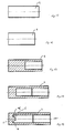
- a first process step ( FIG. 15 ) is the respective blank for the subsequent electrode body 2 of a rod-shaped material to the right one Length to cut.
- the electrode body 2 is now in its original form.
- a second process step ( FIG. 16 ) the blank is cold formed for the first time.
- an external, axial force acts on the blank.
- a fourth process step ( FIG. 18 ) another cupping process takes place, whereby the cavity within the electrode body is further increased.
Landscapes
- Physics & Mathematics (AREA)
- Engineering & Computer Science (AREA)
- Plasma & Fusion (AREA)
- Spectroscopy & Molecular Physics (AREA)
- Plasma Technology (AREA)
- Arc Welding In General (AREA)
Abstract
Description
Gegenstand der Erfindung ist ein Abstandshalter für das Kühlrohr einer Elektrode einer Plasmaschneidvorrichtung.The invention relates to a spacer for the cooling tube of an electrode of a plasma cutting device.
Plasmaschneider werden zum Trennen sämtlicher elektrisch leitfähigen Werkstoffe eingesetzt. Der Plasmaschneider besteht dabei beispielsweise aus einem Inverter, einem Handstück, einem Massekabel, einer Stromzuleitung und einer Druckluftzuleitung.Plasma cutters are used to separate all electrically conductive materials. The plasma cutter consists for example of an inverter, a handpiece, a ground cable, a power supply line and a compressed air supply line.
Folgende Punkte haben sich beim Plasmaschneiden als wesentliche Vorteile herausgestellt:
- Hervorragende Eignung im dünnen und mittleren Baustahlbereich (bis 30 mm)
- Schneiden hochfester Baustähle mit geringer Wärmeeinbringung
- Hohe Schneidgeschwindigkeiten
- Sehr gute, Automatisierbarkeit.
- Excellent suitability in thin and medium structural steel area (up to 30 mm)
- Cutting high strength structural steels with low heat input
- High cutting speeds
- Very good, automatable.
Ein Plasma ist ein elektrisch leitfähiges Gas, wobei ein Lichtbogen fast ausschließlich mit einer Hochfrequenzzündung gezündet wird und am Austritt durch eine isolierte, in der Regel wassergekühlte, Kupferdüse eingeschnürt wird. Durch die hohe Energiedichte schmilzt das Metall. Die Metallschmelze wird durch einen Gasrtrahl weggeblasen, wodurch die Schnittfuge entsteht.A plasma is an electrically conductive gas in which an arc is ignited almost exclusively with high-frequency ignition and is pinched at the outlet by an insulated, usually water-cooled, copper nozzle. The high energy density melts the metal. The molten metal is blown away by a gas stream, creating the kerf.
Die Elektrode einer Plasmaschneldvorrichtung weist einen länglichen Hohlkörper mit einem offenen Ende und einem geschlossenen Ende auf. Sie ist bevorzugt aus Kupfer ausgebildet, es sind jedoch andere Materialien wie Kupfer- und Silberlegierungen möglich. Im unteren Bereich der Elektrode ist mittig ein zylindrischer Einsatz aus einem Material mit hoher thermionischer Emissionsfähigkeit in einer Bohrung eingepresst. Dies Material stellt den Elektrodenkern dar und besteht bevorzugt aus z. B. Hafnium, Zirkonium oder Wolfram.The electrode of a plasma snap device has an elongated hollow body with an open end and a closed end. It is preferably formed of copper, but other materials such as copper and silver alloys are possible. At the bottom of the electrode is a cylindrical insert made of a material with high thermionic center Emissivity pressed in a hole. This material represents the electrode core and is preferably made of z. Hafnium, zirconium or tungsten.
Aus dem Stand der Technik ist es somit bereits bekannt, dass die Kühlflüssigkeit, über ein in der Elektrode innenliegendes Kühlrohr, zum unteren Ende der Elektrode geleitet wird. Durch die zirkulierende Flüssigkeit findet eine ausreichende Kühlung der Elektrode statt.It is thus already known from the state of the art that the cooling liquid is conducted to the lower end of the electrode via a cooling tube lying in the electrode. Due to the circulating liquid, sufficient cooling of the electrode takes place.
Das innenliegende Kühlrohr benötigt gegenüber der Elektrode eine relativ feste Position, um die Eigenschaft der zirkulierenden Kühlströmung gut auszunutzen. Dies stellt einen wichtigen Punkt in Bezug auf die Erhöhung der Lebensdauer der Elektrode dar.The internal cooling tube requires a relatively fixed position relative to the electrode in order to make good use of the characteristic of the circulating cooling flow. This is an important point in terms of increasing the life of the electrode.
Aus dem Stand der Technik ist bereits eine bestimmte Positionierung des Kühlrohres gegenüber dem Elektrodenkörper bekannt.From the prior art, a certain positioning of the cooling tube relative to the electrode body is already known.
Die
Diese Ausführungsform ist jedoch nur sehr aufwendig und kostenintensiv zu produzieren. Durch den Absatz auf der Umfangsfläche des Kühlrohres und den dafür benötigten Anschlag auf der Elektrodenkörperseite ist eine genaue Positionierung schwer möglich.However, this embodiment is very expensive and expensive to produce. Due to the heel on the peripheral surface of the cooling tube and the required stop on the electrode body side accurate positioning is difficult.
Der Erfindung liegt deshalb die Aufgabe zugrunde einen einfachen und universellen Anschlag für das Kühlrohr bereit zustellen.The invention is therefore based on the task of a simple and universal stop for the cooling tube ready.
Zur Lösung der gestellten Aufgabe ist die Erfindung durch die technische Lehre des Anspruches 1 gekennzeichnet.To solve the problem, the invention is characterized by the technical teaching of
Die Lösung der gestellten Aufgabe erfolgt durch die technische Lehre des Anspruches 1.The solution of the problem is achieved by the technical teaching of claim. 1
Wesentliches Merkmal der Erfindung ist, dass auf der Innenseite des Elektrodenkörpers mindestens ein axialer Anschlag für das Kühlrohr ausgebildet ist.An essential feature of the invention is that at least one axial stop for the cooling tube is formed on the inside of the electrode body.
Obwohl die Erfindung auch die Anordnung mehrerer Anschläge vorsieht, wird der einfacheren Beschreibung wegen nur die Anordnung eines einzigen Anschlages näher beschrieben. Dies soll jedoch nicht den Offenbarungsumfang der Erfindung begrenzen. Wenn demnach in der folgenden Beschreibung von einem einzigen Anschlag die Rede ist, so ist dies als "ein oder.mehrere Anschläge" zu verstehen.Although the invention also provides for the arrangement of a plurality of stops, the simpler description will be described only for the arrangement of a single stop closer. However, this is not intended to limit the scope of disclosure of the invention. Thus, if in the following description of a single attack is mentioned, this is to be understood as "one or more attacks".
In einer ersten bevorzugten Ausführungsform besitzt der Elektrodenkörper im unteren Bereich eine mittige Bohrung, die einen Elektrodenkern aufnimmt. Der Elektrodenkern erstreckt sich in Richtung des Innenraums des Elektrodenkörpers und wird durch eine zylindrisch ausgebildete Aufnahme im Elektrodenkörper gehalten. Um eine bessere Kühlung der Elektrode zu gewährleisten, wird im Innenraum des Elektrodenkörpers die Aufnahme des Elektrodenkerns von einer ringförmigen Ausnehmung umgeben, in der die Kühlflüssigkeit zirkulieren kann. Dies ermöglicht eine gute Wärmeableitung und verlängert somit die Lebensdauer der Elektrode.In a first preferred embodiment, the electrode body has a central bore in the lower region, which accommodates an electrode core. The electrode core extends in the direction of the interior of the electrode body and is held by a cylindrically shaped receptacle in the electrode body. To ensure better cooling of the electrode, the receptacle of the electrode core is surrounded by an annular recess in the interior of the electrode body, in which the cooling liquid can circulate. This allows good heat dissipation and thus extends the life of the electrode.
Neu bei der Erfindung ist nun, dass das Kühlrohr durch einen Anschlag in der ringförmigen Ausnehmung auf der Seite der Elektrode beabstandet wird. Dies ermöglicht eine gute Zirkulation der Kühlflüssigkeit im unteren Bereich des Elektrodenkörpers.New in the invention is now that the cooling tube is spaced by a stop in the annular recess on the side of the electrode. This allows a good circulation of the cooling liquid in the lower region of the electrode body.
Somit sieht die Erfindung vor, den die axiale Bewegung des Kühlrohres begrenzenden Anschlag in die Innenseite des Elektrodenkörpers und zwar in die Nähe der Stirnseite des Elektrodenkörpers zu verlagern. Der Anschlag wird also in die umlaufende ringförmige Ausnehmung in der Nähe der Stirnseite des Elektrodenkörpers hinein verlegt.Thus, the invention provides to displace the axial movement of the cooling tube limiting stop in the inside of the electrode body and that in the vicinity of the end face of the electrode body. The stop is thus laid in the circumferential annular recess in the vicinity of the end face of the electrode body inside.
Der Anschlag befindet sich somit auf der Elektrodenseite und kann vorzugsweise als rechteckiger oder runder, sich in axialer Richtung erstreckender Zahn ausgebildet sein. Entscheidend ist, dass die Größe des Anschlags weitgehend nicht den Strömungsfluss der Kühlflüssigkeit beeinträchtigt. Die vordere Stirnseite des Kühlrohres liegt nun an der Stirnseite des in die Kühlflüssigkeit eintauchenden, in axialer Richtung weisenden Zahnes auf.The stop is thus located on the electrode side and may preferably be formed as a rectangular or round, extending in the axial direction tooth. It is crucial that the size of the stop largely does not affect the flow of the cooling liquid. The front end side of the cooling tube is now on the front side of the dipping into the cooling liquid, pointing in the axial direction tooth.
Um eine gute Qualität der Elektrode zusammen mit dem Anschlag zu erreichen, kann in einer bevorzugten Ausführungsform die Elektrode durch ein Pressverfahren hergestellt werden. Mithilfe des Pressverfahrens lässt sich die spezielle Bauform der Elektrode zusammen mit dem axial ausgerichteten Anschlag spanlos herstellen und verringert so eine aufwendige, spanabhebende Nachbearbeitung. Ebenso ist es möglich, den Anschlag für das Kühlrohr in einem zweiten Prozess an den Elektrodenkörper anzubringen.In order to achieve a good quality of the electrode together with the stop, in a preferred embodiment the electrode can be produced by a pressing process. By means of the pressing process, the special design of the electrode can be produced without cutting, together with the axially aligned stop, thus reducing the need for costly, post-machining machining. It is also possible to attach the stop for the cooling tube in a second process to the electrode body.
Statt eines Pressverfahrens kann der zahnförmige Anschlag auch durch eine spanabhebende Bearbeitung der ringförmigen Ausnehmung an der Innenseite des Elektrodenkörpers erreicht werden. In diesem Fall fährt ein in axialer Richtung ausgerichteter Stirnfräser in die zentrale Innenbohrung des Elektrodenkörpers und fräst den Boden der ringförmigen Ausnehmung in Umfangsrichtung fortschreitend um einen Umfangswinkel von z.B. 355 Grad ab, sodass im verbleibenden Winkelbereich von 5 Grad der zahnförmige Anschlag als Materialerhöhung stehen bleibt.Instead of a pressing process, the tooth-shaped stop can also be achieved by a machining of the annular recess on the inside of the electrode body. In this case, an axially aligned end mill travels into the central inner bore of the electrode body and progressively mills the bottom of the annular recess in the circumferential direction by a circumferential angle of e.g. 355 degrees, so that in the remaining angular range of 5 degrees, the tooth-shaped stop stops as material increase.
In einer weiteren Ausführungsform sind in der ringförmigen Ausnehmung am Elektrodenkörper mehrere Anschläge bzw. Anschlagzähne vorhanden, die das Kühlrohr an der Stirnseite anschlagbegrenzend gegenüber der Elektrode positionieren.In a further embodiment, a plurality of stops or stop teeth are present in the annular recess on the electrode body, which position the cooling tube on the front side stop limiting with respect to the electrode.
Statt der Ausbildung von einem oder mehreren axial gerichteten Anschlägen kann auch vorgesehen sein, dass der Anschlag nicht auf dem Grund der ringförmigen Ausnehmung im Elektrodenkörper angeordnet ist, sondern stattdessen an den Seitenwänden der ringförmigen Ausnehmung, wobei sich dann ein in radialer Richtung in den Innenraum der ringförmigen Ausnehmung vorstehender Zahn ergibt.Instead of the formation of one or more axially directed attacks can also be provided that the stop is not located on the bottom of the annular recess in the electrode body, but instead on the side walls of the annular recess, which then in a radial direction in the interior of the annular recess protruding tooth results.
Alle oben beschriebenen Ausführungen beziehen sich darauf, dass der Anschlag werkstoffeinstückig aus dem Material des Elektrodenkörpers heraus gearbeitet ist. Darauf ist die Erfindung nicht beschränkt. Es kann in einer Weiterbildung vorgesehen sein, dass der (axiale oder radiale) Anschlag als Anschlagschraube oder Anschlagstift ausgebildet in dem Material des Elektrodenkörpers verankert ist. Eine solche Verankerung kann lösbar oder unlösbar ausgebildet sein. Sie kann als Klebung, Schweißung, Bohrung oder Verschraubung ausgebildet sein. Hierbei kann ein solcher Anschlag auch aus einem anderen Material als das Material des Elektrodenkörpers bestehen.All the above-described embodiments relate to the fact that the stop is made of one piece material from the material of the electrode body out. The invention is not limited thereto. It may be provided in a development that the (axial or radial) stop is anchored as a stop screw or stop pin anchored in the material of the electrode body. Such an anchoring can be made detachable or non-detachable. It can be designed as gluing, welding, drilling or screwing. In this case, such a stop also consist of a different material than the material of the electrode body.
Schließlich ist in einer weiteren Ausgestaltung vorgesehen, dass der Anschlag an einem Ring angeordnet ist, der in die ringförmige, umlaufende Ausnehmung in den Elektrodenkörper eingelegt oder eingepresst oder in anderer Weise festgelegt ist. Der Ring kann natürlich auch in diese Ausnehmung durch Spannmittel festgelegt sein, um ein Losschlagen oder Ausschwemmen mit der Kühlflüssigkeit zu vermeiden.Finally, it is provided in a further embodiment that the stop is arranged on a ring which is inserted or pressed into the annular, circumferential recess in the electrode body or fixed in some other way. Of course, the ring can also be fixed in this recess by means of clamping means in order to avoid strike-off or flushing with the cooling liquid.
Im Folgenden wird die Erfindung anhand von lediglich einen Ausführungsweg darstellenden Zeichnungen näher erläutert. Hierbei gehen aus den Zeichnungen und ihrer Beschreibung weitere erfindungswesentliche Merkmale und Vorteile der Erfindung hervor.In the following the invention will be explained in more detail with reference to drawings showing only one embodiment. Here are from the drawings and their description further features essential to the invention and advantages of the invention.
Es zeigen:
- Fig. 1:
- Schematische Darstellung einer Plasmaelektrode mit stirnseitigem Anschlag am Elektrodenkörper
- Fig. 2:
- Schematische Darstellung einer Plasmaelektrode mit radialem Anschlag an der Innenwand des Elektrodenkörpers
- Fig.3:
- Schematische Darstellung einer Plasmaelektrode mit einem radialen Anschläg an der Wand der mittigen Aufnahme
- Fig.4:
- Schematische Darstellung einer Plasmaelektrode mit einem radialen, stirnseitigen Anschlag
- Flg.5:
- Schematische Darstellung einer Plasmaelektrode mit einem radialen, stirnseitigen Anschlage
- Fig.6:
- Darstellung einer geschnitten Ansicht der Ausführungsform aus
Figur 1 - Fig.7:
- Perspektivische Darstellung eines Rings mit einem Anschlag für ein Kühlrohr
- Fig.8:
- Darstellung einer abgewandelten Ausführung eines Rings mit zwei radialen, innenliegenden Anschlägen
- Figur 9:
- Schematische Darstellung einer Plasmaelektrode mit einem einseitigen, durchgehenden Anschlag
- Figur 10:
- Schematische Darstellung einer Plasmaelektrode mit einem beidseitigen, mittigen Anschlag
- Figur 11:
- Schematische Darstellung einer Plasmaelektrode mit einem beidseitigen, außenseitigen Anschlag
- Figur 12:
- Schnitt durch den Elektrodenkörper mit randseitigen Anschlägen
- Figur 13:
- Schnitt durch den Elektrodenkörper mit an der mittigen Aufnahme angeordneten Anschlägen
- Figur 14:
- Schnitt durch den Elektrodenkörper mit einem durchgängigen, einseitigen Absatz
Figuren 15 bis 19:- Schematischer Verfahrensablauf einer Herstellung eines Elektrodenkörpers
- Fig. 1:
- Schematic representation of a plasma electrode with an end stop on the electrode body
- Fig. 2:
- Schematic representation of a plasma electrode with a radial stop on the inner wall of the electrode body
- Figure 3:
- Schematic representation of a plasma electrode with a radial Anschläg on the wall of the central receptacle
- Figure 4:
- Schematic representation of a plasma electrode with a radial, end stop
- Flg.5:
- Schematic representation of a plasma electrode with a radial, front stop
- Figure 6:
- Representation of a sectional view of the embodiment of
FIG. 1 - Figure 7:
- Perspective view of a ring with a stop for a cooling tube
- Figure 8:
- Representation of a modified version of a ring with two radial, internal attacks
- FIG. 9:
- Schematic representation of a plasma electrode with a one-sided, continuous stop
- FIG. 10:
- Schematic representation of a plasma electrode with a double-sided, central stop
- FIG. 11:
- Schematic representation of a plasma electrode with a two-sided, outside stop
- FIG. 12:
- Section through the electrode body with marginal attacks
- FIG. 13:
- Section through the electrode body with arranged on the central receptacle attacks
- FIG. 14:
- Section through the electrode body with a continuous, one-sided paragraph
- FIGS. 15 to 19:
- Schematic procedure of a production of an electrode body
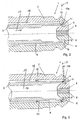
Der längliche, axial verlaufende Elektrodenkörper 2 wird in einer bevorzugten Ausführungsform aus Kupfer hergestellt. Es sind jedoch ebenso Werkstoffe wie beispielsweise Silber- oder Kupferlegierungen möglich.The elongated, axially extending
Der Elektrodenkörper 2 weist ein offenes und ein geschlossenes Ende auf, wobei sich das geschlossene Ende im unteren Bereich befindet.The
Im unteren Bereich weist der Elektrodenkörper 2 eine nach Innen axial erstreckende Aufnahme 5 auf. In der Mitte des Elektrodenkörpers 2 ist eine Bohrung 8 vorhanden und dient zur Aufnahme des Elektrodenkerns 9. Die Bohrung 8 kann entweder als Sackloch- oder Durchgangsbohrung ausgebildet sein.In the lower region, the
Der Elektrodenkern 9 ist in einer bevorzugten Ausführungsform eingepresst. Hierbei ist die Erfindung nicht auf eine Presspassung beschränkt. Es ist ebenso ein Löten, Schweißen oder eine andere Verbindungstechnik möglich. Die Aufnahme 5 für den Elektrodenkern 9 ist Im Innenraum des Elektrodenkörpers 2 radial ausgebildet und bildet ein Teil mit dem Elektrodenkörper 2 aus.The
Der Elektrodenkern 9 ist als Einsatz ausgebildet und besteht aus einem Material mit hoher thermionischer Emissionsfähigkeit. Hierfür kann z. B. Hafnium, Zirkonium oder Wolfram eingesetzt werden. Der Elektrodenkern erstreckt sich ausgehend von dem unteren Ende axial durch die Bohrung 5 in Richtung des Innenraums des Elektrodenkörpers 2.The
Im Innenraum des Elektrodenkörpers 2 erstreckt sich die axiale Aufnahme 5, wobei sich eine ringförmige Ausnehmung 6 zwischen der Aufnahme 5 und der Gehäusewand des Elektrodenkörpers 2 ausbildet. Die ringförmige Ausnehmung 6 dient zur besseren Zirkulation der Kühlflüssigkeit und ermöglicht so eine effektivere Wärmeabfuhr von der Elektrode weg.In the interior of the
Das in die zentrale Mittenbohrung des Elektrodenkörpers 2 eingesetzte Kühlrohr 3 ist dünnwandig, hohl, zylindrisch und vorzugsweise austauschbar.
Aufgrund seines Durchmessers bildet das Kühlrohr 3 in seinem Innenraum einen Flüssigkeitskanal 4 aus, welcher das Strömen einer Kühlflüssigkeit in Pfeilrichtung 19 ermöglicht. Der Außendurchmesser des Kühlrohres 3 ist so ausgebildet, dass er einen Rückfluss der Kühlflüssigkeit zwischen der Innenwand des Elektrodenkörpers 2 und der Außenwand des Kühlrohres 3 durch einen radialen Ringspalt 18 in Pfeilrichtung 23 ermöglicht wird. Somit findet eine Zirkulation der Kühlflüssigkeit innerhalb des Elektrodenkörpers 2 statt.The cooling
Due to its diameter, the cooling
Durch die Bauform des Kühlrohres 3 wird die Kühlflüssigkeit durch den Flüssigkeitskanal 4 in Pfeilrichtung 19 eingeleitet und trifft auf den Elektrodenkern 8 sowie die Aufnahme 5 mit ihrer Innenfläche 7. Danach fließt die Kühlflüssigkeit entlang der Innenfläche 7 der Aufnahme 5 in die ringförmige Ausnehmung 6 und wird aufgrund der Ausbildung des Elektrodenkörpers 2 in den radial außen liegenden Ringraum umgelenkt.Due to the design of the
Die Zirkulation bzw. Umlenkung der Kühlflüssigkeit in der ringförmigen Ausnehmung 6 erfordert eine gewisse axiale Positionierung des Kühlrohrs 3 gegenüber dem Elektrodenkörper 2. Dies wird erfindungsgemäß durch mindestens einen Anschlag 10 erreicht, der sich am Grund der ringförmigen Ausnehmung 25 des Elektrodenkörpers 2 befindet.The circulation or deflection of the cooling liquid in the
Entsprechend der
In einer bevorzugten Ausgestaltung ist der Anschlag 10 als axiale, rechteckige Erhebung ausgebildet und beabstandet, bedingt durch seine Bauform und Position, das Kühlrohr 3 im unteren Bereich des Elektrodenkörpers 2.In a preferred embodiment, the
Der Anschlag 10 weist eine Längsachse 27 auf, welche parallel zur Längsachse des Elektrodenkörpers 2 ist.The
In einer bevorzugten Ausführungsform ist der Anschlag 10 aus dem Material des Elektrodenkörpers 2 gebildet.In a preferred embodiment, the
Durch die Positionierung des Anschlages 10 am Grund 25 der Ausnehmung 6 bildet sich zwischen der Innenseite des Elektrodenkörpers 2 und dem Anschlag 10 ein äußerer Ringnutengrund 13 aus.Due to the positioning of the
Auf der radial, gegenüberliegenden Seite bildet sich zwischen dem Anschlag 10 und der Innenfläche 7 der Aufnahme 5 am Grund 25 der Ausnehmung 6 ein innerer Ringnutengrund 14 aus.On the radially opposite side forms between the
Der Anschlag 10 erstreckt sich in axialer Richtung und weist einen axialen Abstand 21 auf. Der Abstand 21 ergibt sich aus der Stirnseite 22 der Aufnahme 5 und der Stirnseite 20 des Abschlages 10. in einer bevorzugten Ausführungsform der Erfindung beträgt der Abstand 21 etwas 2/3 der axialen Gesamtlänge der Aufnahme 5. Die Erfindung soll jedoch nicht auf diese Längenangabe beschränkt werden. Es ist vielmehr jeder beliebige Abstand möglich.
Neben der rechteckigen Form des Anschlages 10 soll für die vorliegende Erfindung jede andere Form beansprucht werden, die auf Seite des Elektrodenkörpers 2 ausgebildet ist.The
In addition to the rectangular shape of the
Entscheidend bei dieser Ausführungsform ist, dass der Anschlag 10 Teil des Elektrodenkörpers 2 ist und axial, bodenseitig in der Ausnehmung 6 des Elektrodenkörpers 2 angeordnet ist.Decisive in this embodiment is that the
In einer bevorzugten Ausführungsform ist der Anschlag 10 einseitig und als rechteckiger Absatz am Grund 25 derAusnehmung 6 ausgebildet.In a preferred embodiment, the
Durch die Ausbildung und Positionierung des Anschlages 10 ist das Kühlrohr 3 mit seiner Stirnfläche 26 in direkten Kontakt mit der Stirnseite des einseitig ausgebildeten Anschlags 10. In dieser Position ist nDue to the design and positioning of the
Das Kühlwasser kann somit in Pfeilrichtung 19 durch den Flüssigkeitskanal 4 einströmen, trifft auf den Grund 25 der Ausnehmung 6, wird hier umgelenkt und fließt anschließend durch den Ringspalt 18 In Pfeilrichtung 23 wieder ab.The cooling water can thus flow in the direction of
Dadurch, dass der Anschlag 10 nur als einzelner, kleiner, rechteckiger Absatz am Grund der Ausnehmung 6 ausgebildet ist, kann das Kühlmittel fast ohne Widerstand zirkulieren.Characterized in that the
Neu bei dieser Ausführungsform ist, dass sich der Anschlag 10a, ausgehend von der Innenfläche des Elektrodenkörpers 2, radial in Richtung der mittigen Längsachse des Elektrodenkörpers 2 erstreckt. Der Anschlag 10a ist somit mit seiner Längserstreckung radial einwärts gerichtet.What is new in this embodiment is that the
Die Seitenfläche 24 des radial einwärts gerichteten Anschlag 10a ist in direkten Kontakt mit der Stirnfläche 26 des Kühlrohres 3 und wird dadurch von dem Grund 25 der Ausnehmung beabstandet.The
Die Längsachse (27) des Anschlages (10a) Ist senkrecht zur Längsachse des Elektrodenkörpers (2) ausgebildet.The longitudinal axis (27) of the stop (10a) is formed perpendicular to the longitudinal axis of the electrode body (2).
Zwischen dem radial einwärts gerichteten Anschlag 10a und der Aufnahme 5 ist ein Ringspalt 16 ausgebildet, welcher in axialer Richtung von einer radialen Hinterschneidung 15 gefolgt ist. Die Hinterschneidung 15 ermöglicht dem Kühlmittel trotz des Anschlages 10a in der Ausnehmung 6 zu zirkulieren.Between the radially inwardly directed
In einer bevorzugten Ausführungsform ist der Anschlag 10a als einseitiger, einzelner Absatz ausgebildet, welcher an einem Punkt das gesamte Kühlrohr 3 auf Abstand hält. Durch diese Anordnung kann das Kühlmittel weitgehend frei innerhalb der Ausnehmung 6 bzw. des gesamten Elektrodenkörpers 2 zirkulieren.In a preferred embodiment, the
In
Die Längsachse (27) des Anschlages (10b) ist senkrecht zur Längsachse des Elektrodenkörpers (2) ausgebildet.The longitudinal axis (27) of the stop (10b) is formed perpendicular to the longitudinal axis of the electrode body (2).
Entscheidend bei allen Ausführungsbeispielen ist, dass die Anzahl der Anschläge 10, 10', 10a, 10b, 10c, 10d, 10e, 10f nicht auf einen beschränkt ist, ebenso können mehrere Anschläge abstandsbegrenzend für das Kühlrohr 3 innerhalb des Elektrodenkörper 2 angeordnet sein.Decisive in all embodiments is that the number of
In einer bevorzugten Ausführungsform ist der Anschlag 10c als einseitiger Absatz ausgebildet, welcher mit der Stirnfläche 26 des Kühlrohres 3 zusammen wirkt und diese beabstandet.
In a preferred embodiment, the
Zwischen dem Absatz 10c und der Innenwand des Elektrodenkörpers 2 bildet sich ein Ringnutengrund 13 aus.Between the
Durch die einseitige, nicht umlaufende Ausführungsform des Absatzes 10c kann das Kühlmittel weitgehend in der Ausnehmung 6 des Elektrodenkörpers 2 zirkulieren.Due to the one-sided, non-circumferential embodiment of
Die Längsachse (27) des Anschlages (10c) ist parallel zur Längsachse des Elektrodenkörpers (2) ausgebildet.The longitudinal axis (27) of the stop (10c) is formed parallel to the longitudinal axis of the electrode body (2).
Zwischen dem Absatz 10d und der Aufnahme 5 ist eine Ringnut 14 ausgebildet, die ein Zirkulieren des Kühlwassers ermöglicht. Die Ringnut 14 erstreckt sich axial in Richtung des Grundes 25 der Ausnehmung 6.Between the
Der Anschlag 10d ist hierbei so ausgebildet, dass er mit seiner Seitenfläche 24 und der Stirnfläche 26 des Kühlrohres 2 zusammen wirkt und dieses von dem Grund 25 der Ausnehmung 6 beabstandet. Durch diese einseitige Beabstandung ist es dem Kühlmittel möglich, in der verbleibenden Ausnehmung 6 zu zirkulieren.The
Die Längsachse (27) des Anschlages (10d) ist senkrecht zur Längsachse des Elektrodenkörpers (2) ausgebildet.The longitudinal axis (27) of the stop (10d) is formed perpendicular to the longitudinal axis of the electrode body (2).
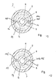
In
Das Kühlrohr 3 ist in diesem Ausführungsbeispiel gestrichelt dargestellt und ist mit in Kontakt mit mindestens einem Anschlag 10 bzw. 10'.The cooling
Der Anschlag 10 erstreckt sich in axialer Richtung und wirkt mit mindestens einer Stelle der Stirnseite des Kühlrohres 3 zusammen.The
Zwischen dem Kühlrohr 3 und der mittleren Aufnahme 5 ist ein innerer Ringnutengrund 14 und zwischen der mittleren Aufnahme 5 und der Innenwand des Elektrodenkörpers 2 ist ein äußerer Rinanutengrund 13 ausgebildetBetween the cooling
An den inneren Ringnutengrund 14 schließt sich in axialer Richtung ein Flüssigkeitskanal 4 an, welcher Teil des Kühlrohres 3 ist. Und an den äußeren Ringnutengrund 13 schließt sich in axialer Richtung ein Ringspalt 18 an, durch welchen das Kühlmittel wieder abfließt.A
In einer weiteren Ausführungsform sind mehrere Anschläge 10' in der ringförmigen Ausnehmung 6 dargestellt, die in
Im eingebauten Zustand kann mithilfe des Rings 11 und dem Anschlagzahn 12 das Kühlrohr 3 fluchtend gegenüber dem Elektrodenkörper 2 in axialer Richtung positioniert werden. Dies ermöglicht eine Zirkulation der Flüssigkeit zwischen der vorderen Stirnseite des Kühlrohrs 3 und dem Elektrodenkörper 2, wobei die ringförmige Ausnehmung 6 die Richtungsumkehr des Kühlmittelstromes bewerkstelligt.When installed, the cooling
Mit der
Der Elektrodenkörper 2 weist in seinem Innenraum in der Ausnehmung 6, einen Anschlage 10e auf, welcher einen durchgehenden Absatz zwischen der Innenwand des Elektrodenkörpers 2 und der Aufnahme 5 ausbildet. Der Anschlag 10e ist hierbei gegenüber der Stirnseite 22 um den Abstand 21 zurück versetzt.With the
The
In einer bevorzugten Ausführungsform ist der Anschlag 10e einseitig bzw. nur in einem Teilbereich der Ausnehmung 6 ausgebildet. Der Teilbereich kann hierbei beispielsweise 30° betragen.In a preferred embodiment, the stop 10e is formed on one side or only in a partial region of the
Entscheidend ist, dass der Anschlag 10e mit seiner Stirnseite 20 mit der Stirnseite des Kühlrohres 3 zusammenwirkt und dieses in axialer Richtung gegenüber dem Grund 25 der Ausnehmung beabstandet.It is crucial that the stop 10e cooperates with its
Auf der gegenüberliegenden, radialen Seite weißt der Elektrodenkörper 2 zwischen der Aufnahmen 5 und der Innenwand des Elektrodenkörpers 2 eine Ausnehmung 6 auf, die eine Zirkulation des Kühlwassers erlaubt.On the opposite, radial side of the
Das Kühlrohr 2 wird somit einseitig durch den Anschlag 10e auf Abstand gehalten, während die Ausnehmung 6 frei ist und ein zirkulieren des Kühlwassers ermöglicht.The cooling
Mit der
Zwischen dem Anschlag 10f und der Innenwand des Elektrodenkörpers 2 ist eine Ringnut 13 ausgebildet, in welcher das Kühlwasser zirkulieren kann.Between the
Die Längsachse (27) des mindestens einen Anschlages (10f) ist parallel zur Längsachse des Elektrodenkörpers (2) ausgebildet.The longitudinal axis (27) of the at least one stop (10f) is formed parallel to the longitudinal axis of the electrode body (2).
Die
Es ist jedoch auch eine Ausführungsform mit nur einem Anschlag 10a möglich.However, an embodiment with only one
Zwischen den Anschlägen 10d und der mittigen Aufnahme 5 weißt der Elektrodenkörper 2 eine Ringnutgrund 14 auf, in der das Kühlwasser zirkulieren kann,Between the
Die Absätze 10d sind so angeordnet, dass sie mit ihrer Stirnseite 20 mit der Stirnfläche 26 des Kühlrohres 3 zusammen wirken und dieses in axialer Richtung von dem Grund 25 der Ausnehmung 6 beabstanden.The
Die Absätze 10d können hierbei entweder vollkommen umlaufend oder auch nur in bestimmten Teilbereichen um die Aufnahme 5 angeordnet sein.The
Die Längsachse (27) des Anschlages (10d) ist senkrecht zur Längsachse des Elektrodenkörpers (2) ausgebildet.The longitudinal axis (27) of the stop (10d) is formed perpendicular to the longitudinal axis of the electrode body (2).
Die
Die Anschläge 10d sind gegenüberliegend, radial nach außen erstreckend an der mittleren Aufnahme 5 angeordnet.The
Zwischen dem Anschlag 10d und der mittleren Aufnahme 5 ist ein Ringnutengrund 14 ausgebildet, welcher sich In axialer Richtung in Form eines Flüssigkeitskanals 4 fortsetzt.Between the
Das Kühlrohr 3 ist gestrichelt dargestellt und ist mit seiner Stirnseite an mindestens zwei Stellen mit den mindestens zwei Anschlägen 10d in Kontakt. Zwischen der Innenwand und dem Kühlrohr 3 bildet sich ein Ringspalt 18 aus.The cooling
Die
Ausgehend von der mittigen Aufnahme 5 erstrecken sich in radialer Richtung mindestens ein Anschlag 10b, 10f.Starting from the
Zwischen den Anschlägen 10f und der Innenwand des Elektrodenkörpers 2 ist ein äußerer Ringnutengrund 13 angeordnet, welcher in axialer Richtung von einem Ringspalt gefolgt wird.Between the
Entscheidend bei allen oben genannten Ausführungsformen ist, dass es sich immer um mindestens einen Anschlag handelt - es können jedoch auch mehr als ein Anschlag Verwendung finden.Crucial in all the above embodiments is that it is always at least one stop - but it can also find more than one stop use.
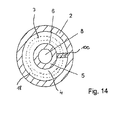
Mit der
Der Elektrodenkörper 2 weist in seinem Innenraum in der Ausnehmung 6, einen Anschlag 10e auf, welcher einen durchgehenden Absatz bzw. eine durchgehende Verbindung zwischen der Innenwand des Elektrodenkörpers 2 und der Aufnahme 5 ausbildet.The
Das Kühlrohr 3 ist hierbei gestrichelt dargestellt und liegt mit seiner Stirnseite einseitige auf dem Anschlag 10e auf und wird dadurch von dem Grund der Ausnehmung 6 beabstandet.The cooling
Mit den
Bei der Herstellung des Elektrodenkörpers handelt es sich um eine KaltUmformung. Hierbei wird der Werkstoff in eine geometrische Form gebracht.The production of the electrode body is a cold forming. Here, the material is brought into a geometric shape.
In einem ersten Verfahrensschritt (
In einem zweiten Verfahrensschritt (
In einem dritten Verfahrensschritt (
Unter Napfen versteht man allgemein eine Massivumformung, bei der das Werkstück bzw. der Rohling in einer Presse zwischen einem Pressstempel und einer Matrize mit erheblichem Drücken verformt wird. ist zwischen Matrizeninnenseite und Stempel ein Hohlraum, in den der Werkstoff durch das Pressen fließt, entsteht im Werkstück eine napfförmige Ausbuchtung entsprechend der Form des Stempels. Je nach Fließrichtung des Werkstoffes spricht man vom Vorwärts- oder Rückwärtsfließpressen.The term "cupping" generally refers to a massive forming in which the workpiece or the blank is deformed in a press between a pressing die and a die with considerable pressure. is between the female inside and punch a cavity into which the material flows by pressing, arises in the workpiece a cup-shaped bulge corresponding to the shape of the punch. Depending on the direction of flow of the material, this is referred to as forward or reverse extrusion.
In einem vierten Verfahrensschritt (
In einem fünften Verfahrensschritt (
Entscheidend ist, dass die Erfindung auf den Ablauf der oben genannten Verfahrensschritte nicht beschränkt ist, es sind auch nur einzelne Verfahrensschritte möglich, um den erfindungswesentlichen Elektrodenkörper herzustellen.It is crucial that the invention is not limited to the sequence of the above-mentioned method steps, but only individual method steps are possible in order to produce the electrode body essential to the invention.
- 1.1.
- Plasmaelektrodeplasma electrode
- 2.Second
- Elektrodenkörperelectrode body
- 3,3,
- Kühlrohrcooling pipe
- 4.4th
- Flüssigkeitskanalliquid channel
- 5.5th
- Aufnahme (unterer Bereich)Recording (lower area)
- 6.6th
- Ausnehmungrecess
- 7.7th
- Innenflächepalm
- 8.8th.
- Bohrungdrilling
- 9.9th
- Elektrodenkernelectrode core
- 10.10th
- Anschlag (10a, b, c, d, e, f)Stop (10a, b, c, d, e, f)
- 11.11th
- Ringring
- 12.12th
- Anschlagzahnstop tooth
- 13.13th
- Ringnutgrund (außen) von 18Ringnutgrund (outside) of 18
- 14.14th
- Ringnutnutgrund (innen)Ring groove groove (inside)
- 15.15th
- Hinterschneidungundercut
- 16.16th
- Ringspalt (innen)Annular gap (inside)
- 17.17th
- Ringspalt (außen)Annular gap (outside)
- 18.18th
- Ringspaltannular gap
- 19.19th
- Pfeilrichtungarrow
- 20.20th
- Stirnseite von 10Front side of 10
- 21.21st
- Abstanddistance
- 22.22nd
- Stirnseite von 5Front side of 5
- 23.23rd
- Pfeilrichtungarrow
- 24.24th
- Seitenfläche von 10Side area of 10
- 25.25th
-
Grund der Ausnehmung 6Base of the
recess 6 - 26.26th
- Stirnfläche von 3Face of 3
- 27.27th
- Längsachse (Anschlag)Longitudinal axis (stop)
Claims (10)
Applications Claiming Priority (1)
| Application Number | Priority Date | Filing Date | Title |
|---|---|---|---|
| DE102009059108A DE102009059108A1 (en) | 2009-12-18 | 2009-12-18 | Electrode with cooling tube for a plasma cutting device |
Publications (3)
| Publication Number | Publication Date |
|---|---|
| EP2364070A2 true EP2364070A2 (en) | 2011-09-07 |
| EP2364070A3 EP2364070A3 (en) | 2013-10-23 |
| EP2364070B1 EP2364070B1 (en) | 2016-04-20 |
Family
ID=43754970
Family Applications (1)
| Application Number | Title | Priority Date | Filing Date |
|---|---|---|---|
| EP10015592.8A Not-in-force EP2364070B1 (en) | 2009-12-18 | 2010-12-14 | Electrode with cooling pipe for a plasma cutting device |
Country Status (2)
| Country | Link |
|---|---|
| EP (1) | EP2364070B1 (en) |
| DE (1) | DE102009059108A1 (en) |
Cited By (2)
| Publication number | Priority date | Publication date | Assignee | Title |
|---|---|---|---|---|
| CN109862682A (en) * | 2019-03-28 | 2019-06-07 | 成都金创立科技有限责任公司 | Plasma generator water-cooled cathode head |
| WO2021155874A1 (en) * | 2020-02-05 | 2021-08-12 | B&Bartoni, spol. s r.o. | Electrode assembly for plasma arc torch with the improved electric current transfer |
Families Citing this family (5)
| Publication number | Priority date | Publication date | Assignee | Title |
|---|---|---|---|---|
| DE102010006786A1 (en) | 2010-02-04 | 2011-08-04 | Holma Ag | Nozzle for a liquid-cooled plasma cutting torch |
| EP2640167B1 (en) * | 2012-03-15 | 2018-02-14 | Manfred Hollberg | Plasma electrode for a plasma cutting device |
| US9114475B2 (en) | 2012-03-15 | 2015-08-25 | Holma Ag | Plasma electrode for a plasma cutting device |
| DE102015001455A1 (en) | 2014-07-15 | 2016-01-21 | Linde Aktiengesellschaft | Electrode for a welding torch for tungsten arc welding and welding torch with such electrode |
| CN116115794A (en) * | 2022-12-08 | 2023-05-16 | 珠海格力电器股份有限公司 | Sterilizing water generating device and cleaning equipment |
Citations (1)
| Publication number | Priority date | Publication date | Assignee | Title |
|---|---|---|---|---|
| EP2082622A1 (en) | 2007-11-27 | 2009-07-29 | Hypertherm, INC. | Method and apparatus for alignment of components of a plasma arc torch |
Family Cites Families (11)
| Publication number | Priority date | Publication date | Assignee | Title |
|---|---|---|---|---|
| GB8904858D0 (en) * | 1989-03-03 | 1989-04-12 | Tetronics Research & Dev Co Li | Improvements in or relating to plasma arc torches |
| US5097111A (en) * | 1990-01-17 | 1992-03-17 | Esab Welding Products, Inc. | Electrode for plasma arc torch and method of fabricating same |
| US5416296A (en) * | 1994-03-11 | 1995-05-16 | American Torch Tip Company | Electrode for plasma arc torch |
| US6215090B1 (en) * | 1998-03-06 | 2001-04-10 | The Esab Group, Inc. | Plasma arc torch |
| US6156995A (en) * | 1998-12-02 | 2000-12-05 | The Esab Group, Inc. | Water-injection nozzle assembly with insulated front end |
| ITRM20010291A1 (en) * | 2001-05-29 | 2002-11-29 | Ct Sviluppo Materiali Spa | PLASMA TORCH |
| US6946617B2 (en) * | 2003-04-11 | 2005-09-20 | Hypertherm, Inc. | Method and apparatus for alignment of components of a plasma arc torch |
| US7081597B2 (en) * | 2004-09-03 | 2006-07-25 | The Esab Group, Inc. | Electrode and electrode holder with threaded connection |
| US7538294B2 (en) * | 2005-05-17 | 2009-05-26 | Huys Industries Limited | Welding electrode and method |
| US7256366B2 (en) * | 2005-12-21 | 2007-08-14 | The Esab Group, Inc. | Plasma arc torch, and methods of assembling and disassembling a plasma arc torch |
| FR2910224A1 (en) * | 2006-12-13 | 2008-06-20 | Air Liquide | PLASMA CUTTING TORCH WITH ADAPTIVE PLUNGER TUBE COOLING CIRCUIT |
-
2009
- 2009-12-18 DE DE102009059108A patent/DE102009059108A1/en not_active Withdrawn
-
2010
- 2010-12-14 EP EP10015592.8A patent/EP2364070B1/en not_active Not-in-force
Patent Citations (1)
| Publication number | Priority date | Publication date | Assignee | Title |
|---|---|---|---|---|
| EP2082622A1 (en) | 2007-11-27 | 2009-07-29 | Hypertherm, INC. | Method and apparatus for alignment of components of a plasma arc torch |
Cited By (2)
| Publication number | Priority date | Publication date | Assignee | Title |
|---|---|---|---|---|
| CN109862682A (en) * | 2019-03-28 | 2019-06-07 | 成都金创立科技有限责任公司 | Plasma generator water-cooled cathode head |
| WO2021155874A1 (en) * | 2020-02-05 | 2021-08-12 | B&Bartoni, spol. s r.o. | Electrode assembly for plasma arc torch with the improved electric current transfer |
Also Published As
| Publication number | Publication date |
|---|---|
| EP2364070B1 (en) | 2016-04-20 |
| EP2364070A3 (en) | 2013-10-23 |
| DE102009059108A1 (en) | 2011-06-22 |
Similar Documents
| Publication | Publication Date | Title |
|---|---|---|
| EP2364070B1 (en) | Electrode with cooling pipe for a plasma cutting device | |
| DE2448160C2 (en) | ||
| EP0223909B1 (en) | Extrusion die for manufacturing a drill blank of hard metal or ceramics | |
| DE19710261B4 (en) | Method of making a hose coupling | |
| EP2809497B1 (en) | Expansion head for expansion tools and expansion tool comprising said expansion head | |
| EP0739454A1 (en) | Self-boring, thread-milling screw with a flow forming | |
| EP2362508B1 (en) | Method for sheathing an electrical wire with an elastic sealing element | |
| WO2011023428A1 (en) | Tool | |
| DE1121151B (en) | Socket | |
| DE19800097A1 (en) | Manufacturing procedure for cutting tool | |
| EP1668236A1 (en) | Combustion chamber comprising a cooling unit and method for producing said combustion chamber | |
| DE2240148A1 (en) | METHOD AND DEVICE FOR MANUFACTURING PIPES OR TUBE-SHAPED BODIES WITH IRREGULAR SHAPED INNER WALLS | |
| DE2137990B2 (en) | Fuse | |
| DE102009012938A1 (en) | Cutting tool for deep hole boring, has cylindrical shaft and shaft end with cut part in front side, and sleeve mounted at shaft in longitudinally-movable manner, where inner diameter of sleeve is slightly larger than outer diameter of shaft | |
| DE2404129C3 (en) | Electric arc torch | |
| DE102017208039B4 (en) | Process for manufacturing a rotary tool and rotary tool | |
| EP2640167B1 (en) | Plasma electrode for a plasma cutting device | |
| DE102008010192A1 (en) | A method of connecting an exhaust pipe to a flange and a flange-exhaust pipe connection and resistance pressure welding device produced thereby | |
| DE102014000661B4 (en) | cable end sleeve | |
| DE10144516B4 (en) | plasma torch | |
| EP2642831A1 (en) | Plasma electrode for a plasma arc torch and method for its manufacture | |
| DE7517897U (en) | Crimp sleeve connection | |
| WO2009030431A2 (en) | Laser machining head for machining a work piece by means of a laser beam, said laser machining head having a housing that is connected thereto in a detachable fashion, receiving device and nozzle; nozzle element having a rounded off tapered section; receiving device | |
| DE19955666A1 (en) | Connecting coaxial cable by pushing against lugs which bend, to penetrate insulation when cable withdrawn | |
| DE102007004118A1 (en) | pierce nut |
Legal Events
| Date | Code | Title | Description |
|---|---|---|---|
| PUAI | Public reference made under article 153(3) epc to a published international application that has entered the european phase |
Free format text: ORIGINAL CODE: 0009012 |
|
| AK | Designated contracting states |
Kind code of ref document: A2 Designated state(s): AL AT BE BG CH CY CZ DE DK EE ES FI FR GB GR HR HU IE IS IT LI LT LU LV MC MK MT NL NO PL PT RO RS SE SI SK SM TR |
|
| AX | Request for extension of the european patent |
Extension state: BA ME |
|
| RAP1 | Party data changed (applicant data changed or rights of an application transferred) |
Owner name: HOLLBERG, MANFRED |
|
| PUAL | Search report despatched |
Free format text: ORIGINAL CODE: 0009013 |
|
| AK | Designated contracting states |
Kind code of ref document: A3 Designated state(s): AL AT BE BG CH CY CZ DE DK EE ES FI FR GB GR HR HU IE IS IT LI LT LU LV MC MK MT NL NO PL PT RO RS SE SI SK SM TR |
|
| AX | Request for extension of the european patent |
Extension state: BA ME |
|
| RIC1 | Information provided on ipc code assigned before grant |
Ipc: H05H 1/34 20060101AFI20130918BHEP |
|
| 17P | Request for examination filed |
Effective date: 20140120 |
|
| RBV | Designated contracting states (corrected) |
Designated state(s): AL AT BE BG CH CY CZ DE DK EE ES FI FR GB GR HR HU IE IS IT LI LT LU LV MC MK MT NL NO PL PT RO RS SE SI SK SM TR |
|
| GRAP | Despatch of communication of intention to grant a patent |
Free format text: ORIGINAL CODE: EPIDOSNIGR1 |
|
| INTG | Intention to grant announced |
Effective date: 20160104 |
|
| GRAS | Grant fee paid |
Free format text: ORIGINAL CODE: EPIDOSNIGR3 |
|
| GRAA | (expected) grant |
Free format text: ORIGINAL CODE: 0009210 |
|
| AK | Designated contracting states |
Kind code of ref document: B1 Designated state(s): AL AT BE BG CH CY CZ DE DK EE ES FI FR GB GR HR HU IE IS IT LI LT LU LV MC MK MT NL NO PL PT RO RS SE SI SK SM TR |
|
| REG | Reference to a national code |
Ref country code: GB Ref legal event code: FG4D Free format text: NOT ENGLISH |
|
| REG | Reference to a national code |
Ref country code: CH Ref legal event code: EP |
|
| REG | Reference to a national code |
Ref country code: AT Ref legal event code: REF Ref document number: 793659 Country of ref document: AT Kind code of ref document: T Effective date: 20160515 |
|
| REG | Reference to a national code |
Ref country code: IE Ref legal event code: FG4D Free format text: LANGUAGE OF EP DOCUMENT: GERMAN |
|
| REG | Reference to a national code |
Ref country code: DE Ref legal event code: R096 Ref document number: 502010011461 Country of ref document: DE |
|
| REG | Reference to a national code |
Ref country code: NL Ref legal event code: FP |
|
| REG | Reference to a national code |
Ref country code: LT Ref legal event code: MG4D |
|
| PG25 | Lapsed in a contracting state [announced via postgrant information from national office to epo] |
Ref country code: LT Free format text: LAPSE BECAUSE OF FAILURE TO SUBMIT A TRANSLATION OF THE DESCRIPTION OR TO PAY THE FEE WITHIN THE PRESCRIBED TIME-LIMIT Effective date: 20160420 Ref country code: PL Free format text: LAPSE BECAUSE OF FAILURE TO SUBMIT A TRANSLATION OF THE DESCRIPTION OR TO PAY THE FEE WITHIN THE PRESCRIBED TIME-LIMIT Effective date: 20160420 Ref country code: FI Free format text: LAPSE BECAUSE OF FAILURE TO SUBMIT A TRANSLATION OF THE DESCRIPTION OR TO PAY THE FEE WITHIN THE PRESCRIBED TIME-LIMIT Effective date: 20160420 Ref country code: NO Free format text: LAPSE BECAUSE OF FAILURE TO SUBMIT A TRANSLATION OF THE DESCRIPTION OR TO PAY THE FEE WITHIN THE PRESCRIBED TIME-LIMIT Effective date: 20160720 |
|
| PG25 | Lapsed in a contracting state [announced via postgrant information from national office to epo] |
Ref country code: ES Free format text: LAPSE BECAUSE OF FAILURE TO SUBMIT A TRANSLATION OF THE DESCRIPTION OR TO PAY THE FEE WITHIN THE PRESCRIBED TIME-LIMIT Effective date: 20160420 Ref country code: RS Free format text: LAPSE BECAUSE OF FAILURE TO SUBMIT A TRANSLATION OF THE DESCRIPTION OR TO PAY THE FEE WITHIN THE PRESCRIBED TIME-LIMIT Effective date: 20160420 Ref country code: GR Free format text: LAPSE BECAUSE OF FAILURE TO SUBMIT A TRANSLATION OF THE DESCRIPTION OR TO PAY THE FEE WITHIN THE PRESCRIBED TIME-LIMIT Effective date: 20160721 Ref country code: PT Free format text: LAPSE BECAUSE OF FAILURE TO SUBMIT A TRANSLATION OF THE DESCRIPTION OR TO PAY THE FEE WITHIN THE PRESCRIBED TIME-LIMIT Effective date: 20160822 Ref country code: LV Free format text: LAPSE BECAUSE OF FAILURE TO SUBMIT A TRANSLATION OF THE DESCRIPTION OR TO PAY THE FEE WITHIN THE PRESCRIBED TIME-LIMIT Effective date: 20160420 Ref country code: HR Free format text: LAPSE BECAUSE OF FAILURE TO SUBMIT A TRANSLATION OF THE DESCRIPTION OR TO PAY THE FEE WITHIN THE PRESCRIBED TIME-LIMIT Effective date: 20160420 Ref country code: SE Free format text: LAPSE BECAUSE OF FAILURE TO SUBMIT A TRANSLATION OF THE DESCRIPTION OR TO PAY THE FEE WITHIN THE PRESCRIBED TIME-LIMIT Effective date: 20160420 |
|
| REG | Reference to a national code |
Ref country code: DE Ref legal event code: R097 Ref document number: 502010011461 Country of ref document: DE |
|
| PG25 | Lapsed in a contracting state [announced via postgrant information from national office to epo] |
Ref country code: SK Free format text: LAPSE BECAUSE OF FAILURE TO SUBMIT A TRANSLATION OF THE DESCRIPTION OR TO PAY THE FEE WITHIN THE PRESCRIBED TIME-LIMIT Effective date: 20160420 Ref country code: RO Free format text: LAPSE BECAUSE OF FAILURE TO SUBMIT A TRANSLATION OF THE DESCRIPTION OR TO PAY THE FEE WITHIN THE PRESCRIBED TIME-LIMIT Effective date: 20160420 Ref country code: EE Free format text: LAPSE BECAUSE OF FAILURE TO SUBMIT A TRANSLATION OF THE DESCRIPTION OR TO PAY THE FEE WITHIN THE PRESCRIBED TIME-LIMIT Effective date: 20160420 Ref country code: DK Free format text: LAPSE BECAUSE OF FAILURE TO SUBMIT A TRANSLATION OF THE DESCRIPTION OR TO PAY THE FEE WITHIN THE PRESCRIBED TIME-LIMIT Effective date: 20160420 |
|
| PLBE | No opposition filed within time limit |
Free format text: ORIGINAL CODE: 0009261 |
|
| STAA | Information on the status of an ep patent application or granted ep patent |
Free format text: STATUS: NO OPPOSITION FILED WITHIN TIME LIMIT |
|
| PG25 | Lapsed in a contracting state [announced via postgrant information from national office to epo] |
Ref country code: SM Free format text: LAPSE BECAUSE OF FAILURE TO SUBMIT A TRANSLATION OF THE DESCRIPTION OR TO PAY THE FEE WITHIN THE PRESCRIBED TIME-LIMIT Effective date: 20160420 |
|
| 26N | No opposition filed |
Effective date: 20170123 |
|
| PG25 | Lapsed in a contracting state [announced via postgrant information from national office to epo] |
Ref country code: SI Free format text: LAPSE BECAUSE OF FAILURE TO SUBMIT A TRANSLATION OF THE DESCRIPTION OR TO PAY THE FEE WITHIN THE PRESCRIBED TIME-LIMIT Effective date: 20160420 Ref country code: BE Free format text: LAPSE BECAUSE OF NON-PAYMENT OF DUE FEES Effective date: 20161231 |
|
| REG | Reference to a national code |
Ref country code: CH Ref legal event code: PL |
|
| PG25 | Lapsed in a contracting state [announced via postgrant information from national office to epo] |
Ref country code: MC Free format text: LAPSE BECAUSE OF FAILURE TO SUBMIT A TRANSLATION OF THE DESCRIPTION OR TO PAY THE FEE WITHIN THE PRESCRIBED TIME-LIMIT Effective date: 20160420 |
|
| REG | Reference to a national code |
Ref country code: FR Ref legal event code: ST Effective date: 20170831 |
|
| REG | Reference to a national code |
Ref country code: IE Ref legal event code: MM4A |
|
| PG25 | Lapsed in a contracting state [announced via postgrant information from national office to epo] |
Ref country code: LI Free format text: LAPSE BECAUSE OF NON-PAYMENT OF DUE FEES Effective date: 20161231 Ref country code: LU Free format text: LAPSE BECAUSE OF NON-PAYMENT OF DUE FEES Effective date: 20161214 Ref country code: FR Free format text: LAPSE BECAUSE OF NON-PAYMENT OF DUE FEES Effective date: 20170102 Ref country code: CH Free format text: LAPSE BECAUSE OF NON-PAYMENT OF DUE FEES Effective date: 20161231 |
|
| PG25 | Lapsed in a contracting state [announced via postgrant information from national office to epo] |
Ref country code: IE Free format text: LAPSE BECAUSE OF NON-PAYMENT OF DUE FEES Effective date: 20161214 |
|
| REG | Reference to a national code |
Ref country code: BE Ref legal event code: MM Effective date: 20161231 |
|
| REG | Reference to a national code |
Ref country code: AT Ref legal event code: MM01 Ref document number: 793659 Country of ref document: AT Kind code of ref document: T Effective date: 20161214 |
|
| PG25 | Lapsed in a contracting state [announced via postgrant information from national office to epo] |
Ref country code: AT Free format text: LAPSE BECAUSE OF NON-PAYMENT OF DUE FEES Effective date: 20161214 Ref country code: HU Free format text: LAPSE BECAUSE OF FAILURE TO SUBMIT A TRANSLATION OF THE DESCRIPTION OR TO PAY THE FEE WITHIN THE PRESCRIBED TIME-LIMIT; INVALID AB INITIO Effective date: 20101214 Ref country code: CY Free format text: LAPSE BECAUSE OF FAILURE TO SUBMIT A TRANSLATION OF THE DESCRIPTION OR TO PAY THE FEE WITHIN THE PRESCRIBED TIME-LIMIT Effective date: 20160420 |
|
| PG25 | Lapsed in a contracting state [announced via postgrant information from national office to epo] |
Ref country code: MK Free format text: LAPSE BECAUSE OF FAILURE TO SUBMIT A TRANSLATION OF THE DESCRIPTION OR TO PAY THE FEE WITHIN THE PRESCRIBED TIME-LIMIT Effective date: 20160420 Ref country code: TR Free format text: LAPSE BECAUSE OF FAILURE TO SUBMIT A TRANSLATION OF THE DESCRIPTION OR TO PAY THE FEE WITHIN THE PRESCRIBED TIME-LIMIT Effective date: 20160420 Ref country code: IS Free format text: LAPSE BECAUSE OF FAILURE TO SUBMIT A TRANSLATION OF THE DESCRIPTION OR TO PAY THE FEE WITHIN THE PRESCRIBED TIME-LIMIT Effective date: 20160420 |
|
| PG25 | Lapsed in a contracting state [announced via postgrant information from national office to epo] |
Ref country code: BG Free format text: LAPSE BECAUSE OF FAILURE TO SUBMIT A TRANSLATION OF THE DESCRIPTION OR TO PAY THE FEE WITHIN THE PRESCRIBED TIME-LIMIT Effective date: 20160420 |
|
| PG25 | Lapsed in a contracting state [announced via postgrant information from national office to epo] |
Ref country code: MT Free format text: LAPSE BECAUSE OF FAILURE TO SUBMIT A TRANSLATION OF THE DESCRIPTION OR TO PAY THE FEE WITHIN THE PRESCRIBED TIME-LIMIT Effective date: 20160420 |
|
| PG25 | Lapsed in a contracting state [announced via postgrant information from national office to epo] |
Ref country code: AL Free format text: LAPSE BECAUSE OF FAILURE TO SUBMIT A TRANSLATION OF THE DESCRIPTION OR TO PAY THE FEE WITHIN THE PRESCRIBED TIME-LIMIT Effective date: 20160420 |
|
| PGFP | Annual fee paid to national office [announced via postgrant information from national office to epo] |
Ref country code: NL Payment date: 20191217 Year of fee payment: 10 |
|
| PGFP | Annual fee paid to national office [announced via postgrant information from national office to epo] |
Ref country code: GB Payment date: 20201222 Year of fee payment: 11 Ref country code: DE Payment date: 20201216 Year of fee payment: 11 Ref country code: CZ Payment date: 20201203 Year of fee payment: 11 |
|
| PGFP | Annual fee paid to national office [announced via postgrant information from national office to epo] |
Ref country code: IT Payment date: 20201230 Year of fee payment: 11 |
|
| REG | Reference to a national code |
Ref country code: NL Ref legal event code: MM Effective date: 20210101 |
|
| PG25 | Lapsed in a contracting state [announced via postgrant information from national office to epo] |
Ref country code: NL Free format text: LAPSE BECAUSE OF NON-PAYMENT OF DUE FEES Effective date: 20210101 |
|
| REG | Reference to a national code |
Ref country code: DE Ref legal event code: R119 Ref document number: 502010011461 Country of ref document: DE |
|
| PG25 | Lapsed in a contracting state [announced via postgrant information from national office to epo] |
Ref country code: CZ Free format text: LAPSE BECAUSE OF NON-PAYMENT OF DUE FEES Effective date: 20211214 |
|
| GBPC | Gb: european patent ceased through non-payment of renewal fee |
Effective date: 20211214 |
|
| PG25 | Lapsed in a contracting state [announced via postgrant information from national office to epo] |
Ref country code: GB Free format text: LAPSE BECAUSE OF NON-PAYMENT OF DUE FEES Effective date: 20211214 Ref country code: DE Free format text: LAPSE BECAUSE OF NON-PAYMENT OF DUE FEES Effective date: 20220701 |
|
| PG25 | Lapsed in a contracting state [announced via postgrant information from national office to epo] |
Ref country code: IT Free format text: LAPSE BECAUSE OF NON-PAYMENT OF DUE FEES Effective date: 20211214 |