EP2364051B1 - Procédé et appareil permettant d'indiquer les impératifs de places pour communiquer les capacités d'un dispositif - Google Patents
Procédé et appareil permettant d'indiquer les impératifs de places pour communiquer les capacités d'un dispositif Download PDFInfo
- Publication number
- EP2364051B1 EP2364051B1 EP10290108.9A EP10290108A EP2364051B1 EP 2364051 B1 EP2364051 B1 EP 2364051B1 EP 10290108 A EP10290108 A EP 10290108A EP 2364051 B1 EP2364051 B1 EP 2364051B1
- Authority
- EP
- European Patent Office
- Prior art keywords
- mobile station
- capabilities
- radio access
- network
- data transfer
- Prior art date
- Legal status (The legal status is an assumption and is not a legal conclusion. Google has not performed a legal analysis and makes no representation as to the accuracy of the status listed.)
- Active
Links
Images


Classifications
-
- H—ELECTRICITY
- H04—ELECTRIC COMMUNICATION TECHNIQUE
- H04W—WIRELESS COMMUNICATION NETWORKS
- H04W8/00—Network data management
- H04W8/22—Processing or transfer of terminal data, e.g. status or physical capabilities
- H04W8/24—Transfer of terminal data
-
- H—ELECTRICITY
- H04—ELECTRIC COMMUNICATION TECHNIQUE
- H04W—WIRELESS COMMUNICATION NETWORKS
- H04W4/00—Services specially adapted for wireless communication networks; Facilities therefor
- H04W4/70—Services for machine-to-machine communication [M2M] or machine type communication [MTC]
-
- H—ELECTRICITY
- H04—ELECTRIC COMMUNICATION TECHNIQUE
- H04W—WIRELESS COMMUNICATION NETWORKS
- H04W60/00—Affiliation to network, e.g. registration; Terminating affiliation with the network, e.g. de-registration
-
- H—ELECTRICITY
- H04—ELECTRIC COMMUNICATION TECHNIQUE
- H04W—WIRELESS COMMUNICATION NETWORKS
- H04W72/00—Local resource management
- H04W72/04—Wireless resource allocation
-
- H—ELECTRICITY
- H04—ELECTRIC COMMUNICATION TECHNIQUE
- H04W—WIRELESS COMMUNICATION NETWORKS
- H04W72/00—Local resource management
- H04W72/04—Wireless resource allocation
- H04W72/044—Wireless resource allocation based on the type of the allocated resource
- H04W72/0453—Resources in frequency domain, e.g. a carrier in FDMA
-
- H—ELECTRICITY
- H04—ELECTRIC COMMUNICATION TECHNIQUE
- H04W—WIRELESS COMMUNICATION NETWORKS
- H04W72/00—Local resource management
- H04W72/20—Control channels or signalling for resource management
- H04W72/23—Control channels or signalling for resource management in the downlink direction of a wireless link, i.e. towards a terminal
-
- H—ELECTRICITY
- H04—ELECTRIC COMMUNICATION TECHNIQUE
- H04W—WIRELESS COMMUNICATION NETWORKS
- H04W8/00—Network data management
- H04W8/22—Processing or transfer of terminal data, e.g. status or physical capabilities
Definitions
- the present disclosure relates generally to network communications and, more particularly, to methods and apparatus to indicate space requirements for communicating capabilities of a device.
- Mobile communication devices exchange information with mobile communication networks by signaling requests to connect with the mobile communication networks. Such is the case when placing telephone calls and/or transmitting data using mobile communication devices.
- a mobile communication device can establish such a data transfer session with a network by signaling its communication capabilities to the network and requesting that the network allocate a data channel for use by the mobile communication device to transfer its data to the network.
- Document US2002/0080758 discloses that a mobile station can request an assignment of a block for transmitting information related to radio capability in the uplink direction, repeating the request if the information is too long to fit.
- the invention relates to a method, an apparatus and a computer readable medium to communicate capabilities of a device, as defined respectively in claim 1 , claim 8 and claim 15.
- Optional features of the invention are further defined in claims 2 to 7 and 9 to 14.
- Mobile stations such as mobile communication devices, mobile computing devices, or any other element, entity, device, or service capable of communicating wirelessly with a wireless network.
- Mobile stations also referred to as terminals, wireless terminals, or user equipment (UE)
- UE may include mobile smart phones (e.g., a BlackBerry® smart phone), wireless personal digital assistants (PDA), laptop/notebook/netbook computers with wireless adapters, etc.
- mobile smart phones e.g., a BlackBerry® smart phone
- PDA personal digital assistants
- laptop/notebook/netbook computers with wireless adapters etc.
- the example methods and apparatus described herein can be used to signal capabilities of mobile stations (e.g., access-stratum radio access capabilities) for data transfer sessions between the mobile stations and access networks.
- the example methods and apparatus are described herein as being implemented in connection with GSM (Global System for Mobile communications) networks, General Packet Radio Service (GPRS) networks, Enhanced Data Rates for GSM Evolution (EDGE) networks (or Enhanced GPRS (EGPRS)), and other mobile communication networks to implement data transfers between such networks and mobile stations.
- GSM Global System for Mobile communications
- GPRS General Packet Radio Service
- EDGE Enhanced Data Rates for GSM Evolution
- GPRS Enhanced GPRS
- the example methods and apparatus may additionally or alternatively be implemented in connection with other types of wireless networks including other types of mobile communication networks to implement data transfers.
- the example methods and apparatus disclosed herein can be used in connection with different types of data transfer sessions including, for example, small data transfer (SDT) sessions, machine-to-machine data transfer sessions, uplink data transfer sessions, and/or any other type of data transfer sessions including any combination thereof.
- Data transfers enable mobile stations to send data to networks on an as-needed basis and can be triggered by different subsystems of a mobile station upon the need to send information to a network. Such information may be generated by the mobile station (e.g., mobile station status information) or may be user-generated information (e.g., messaging, profile changes).
- a mobile station may request a connection (e.g., one or more resources for uplink transmission) with a network.
- a network may allocate resources (e.g., data channels, timeslots, spreading codes, etc.) to a mobile station in accordance with radio access capabilities (RACs) of the mobile station.
- resources e.g., data channels, timeslots, spreading codes, etc.
- a temporary block flow (TBF) is an example of a data transfer session.
- the capabilities of the mobile station that are known to the network affect the manner in which the network communicates with the mobile station. For instance, the network may limit a connection with the mobile station to particular features or may enable further features for the connection based on the capabilities of the mobile station. Therefore, the mobile station may perform a capabilities signaling to communicate information concerning its radio access capabilities to a radio access network. Such capabilities can be related to packet switched radio access capabilities or circuit switched radio access capabilities.
- Examples of different types of radio access capabilities communicated by the mobile station to the network include supported GSM frequency bands (e.g., GSM 900, GSM 1800, GSM 1900), multislot classes associated with different modes of operation (e.g., GPRS multislot class, EGPRS multislot class, dual transfer mode (DTM) multislot class for GPRS or EGPRS, high multislot class), radio transmission capabilities (e.g., radio frequency (RF) power capabilities, 8 phase shift keying (8PSK) power capabilities, Gaussian minimum shift keying (GMSK) / 8PSK power profile), supported features (e.g., Downlink Advanced Receiver Performance (DARP), packet-switched (PS) handover, flexible timeslot assignment, reduced latency, downlink dual carrier, uplink / downlink EGPRS2), and additional supported radio access technologies (e.g., Universal Mobile Telecommunications System (UMTS) frequency-division duplexing (FDD) or time-division duplexing (TDD), code division multiple access (
- Radio access capabilities of a mobile station may be signaled or sent to an access network using a two-phase access procedure or a one-phase access procedure.
- a two-phase access procedure enables sending relatively more capabilities information of a mobile station to an access network prior to setting up a data transfer session between the mobile station and the access network than does a one-phase access procedure.
- Example two-phase and one-phase access procedures are depicted in FIGS. 2 and 3 and are described below in connection with the example methods and apparatus disclosed herein.
- a drawback of using known capabilities signaling techniques in connection with the two-phase access or one-phase access procedures is that mobile stations, in some instances, cannot communicate all of their radio access capabilities in order to perform data transfer sessions.
- a single message (a channel request message) is used by the mobile station to obtain a data channel allocation from an access network to allow the mobile station to perform its data transfer.
- the channel request message in the one-phase access procedure provides limited space (e.g., two bits) for communicating the radio access capabilities of the mobile station. Thus, relatively little information to describe the capabilities of the mobile station can be communicated to the access network using the one-phase access procedure.
- the two-phase access procedure provides one or two messages for use by the mobile station to communicate its radio access capabilities to the access network prior to establishing a data transfer session.
- known capabilities signaling techniques associated with the two-phase access procedure also often do not provide sufficient space to transfer the complete radio access capabilities of a mobile station.
- Two previously specified and accepted techniques for the two-phase access procedure are used in known systems.
- the first technique requires that a mobile station repeats all capabilities for each GSM frequency band (i.e., an Access Technology Type) supported by the mobile station, even though the capabilities may be the same across every frequency band supported by that mobile station. Thus, use of the first technique can result in a relatively high rate of redundancy.
- a mobile station In the second technique, a mobile station must include the full capabilities only for one GSM frequency band and communicate a reduced capabilities set for other bands for which the mobile station has the same basic capabilities. Thus, in the second technique, the mobile station need not repeat capabilities that are common to all of its supported frequency bands.
- MS radio access capability IE mobile station radio access capability information element
- the MS radio access capability IE can be truncated as required, depending on the available space in a message in which it is being sent by a mobile station. Newer capabilities information is typically appended to the end of the MS radio access capability IE in chronological order of the specification of the corresponding feature/capability. Truncating the MS radio access capability IE affects the ability to communicate relatively newer (e.g., more recently specified) capabilities to an access network while a mobile station attempts to establish a data transfer session. Thus, a truncated MS radio access capability IE may result in the access network not advantageously using features that the mobile station supports. That is, upon receiving a MS radio access capability IE from a mobile station, an access network must assume that the mobile station does not support any feature and/or frequency band which is not explicitly indicated (e.g., truncated capabilities) as being supported.
- the data transfer setup signaling messages may require transmitting more information than the relatively small quantity (e.g., a quantity of data below a pre-determined threshold characteristic of small data transfers) of data transmitted during a small data transfer session such that the signaling overhead to establish communications may become relatively significant in comparison to the transmitted data.
- the impact of such inefficient signaling can have a significantly negative impact on battery life of a mobile station, on the utilization of network resources, and on the time required for performing the data transfer.
- the example methods and apparatus disclosed herein provide relatively more efficient procedures and data formats that can be used to communicate radio access capabilities of mobile stations to access networks for establishing data transfer connections.
- the example techniques disclosed herein involve omitting capabilities from a MS radio access capabilities IE that are not relevant to a type of use for a particular data transfer session and/or omitting legacy radio access capabilities.
- Relevant capabilities may include, for example, relevant multislot classes, relevant switching times, and relevant packet switched handover capabilities indicated by a mobile station to an access network as supported by the mobile station.
- the techniques described herein enable or facilitate omitting capabilities not related to GSM communications (or not relevant to an access technology used between a mobile station and an access network and/or core network).
- some techniques described herein may be used to implicitly or expressly inform an access network when radio access capabilities information communicated by a mobile station is not complete and may further indicate that further (e.g., complete) radio access capabilities of the mobile station can be obtained from a core network.
- some omitted legacy radio access capabilities are mandatory capabilities that are assumed by access networks as being supported by mobile stations (e.g., based on the indicated support of other, non-mandatory features, or based on the use of any of the techniques described herein), while other omitted legacy radio access capabilities are those that are typically no longer used to establish data transfer connections with access networks.
- the mobile station can generate a message having a structural format that is adaptable or changeable to indicate different radio access capabilities information of the mobile station.
- the mobile station can indicate a relevant subset of its different radio access capabilities in the message.
- the indicated subset can be associated with a specific type of use (e.g., a machine-to-machine data transfer use, an uplink data transfer use, a small data transfer use) by the mobile station for the data transfer session.
- the mobile station can then send the message to the network to request a data channel resource for a data transfer connection.
- Example use-type capabilities structures include a machine type communication (MTC) capabilities structure, an uplink capabilities structure, a small data transfer (SDT) capabilities structure, and a general capabilities structure.
- MTC capabilities structure can be used by a mobile station to communicate relevant radio access capabilities when establishing a machine-to-machine data transfer session.
- the uplink capabilities structure can be used by a mobile station to communicate relevant radio access capabilities when establishing a data transfer session for an uplink only data transfer.
- the SDT capabilities structure can be used by a mobile station to communicate relevant radio access capabilities when establishing a data transfer session for a small data transfer.
- the general capabilities structure (e.g., an exhaustive or complete capabilities structure) can be used to communicate an exhaustive or full list of radio access capabilities of a mobile station when establishing a data transfer session.
- the general capabilities structure can be used when a use-type of a data transfer session is undetermined, when the data transfer session is to be used for multiple types of uses (e.g., a multi-purpose data transfer), or when a radio access capabilities structure for a particular use-type is not supported by an access network.
- a mobile station can use use-type radio access capabilities structures in a mutually exclusive manner based on their relevancy to particular types of data transfer sessions. For example, when establishing a machine-to-machine data transfer session, a mobile station can communicate radio access capabilities of a MTC capabilities structure without communicating capabilities described in other use-type structures.
- a mobile station selects a use-type capabilities structure from a group of different use-type capabilities structures, each of which is indicative of a different set of radio access capabilities that the mobile station supports (and which further may implicitly indicate the mobile station's support of one or more additional features or capabilities) and that are relevant to a particular type of data transfer session between the mobile station and the wireless network.
- the mobile station can then format a structural format of a message or an information element (e.g., an information field) in a message based on the selected use-type capabilities structure to indicate the radio access capabilities information corresponding to the selected use-type capabilities structure.
- the mobile station includes a code in the message that is indicative of the presence of the selected use-type capabilities structure in the message.
- the mobile station 102 sends the message to the wireless network to request a data channel resource based on the indicated radio access capabilities.
- RAC configuration IDs radio access capabilities configuration identifiers
- a mobile station can inform a network of its support of the radio access capabilities corresponding to a particular RAC configuration ID using only a few bits. For example, the mobile station can generate a message to initiate a data transfer session between itself and a network.
- the mobile station can select a code value from a plurality of code values, each of the code values pre-defined to indicate a respective subset of radio access capabilities of the mobile station.
- the mobile station can include the selected code value in the message and send the message to the network.
- the mobile station can select and include multiple such code values in the message to indicate a particular combination of pre-defined radio access capabilities.
- a mobile station can request a particular quantity of communication blocks to be allocated by a network for use by the mobile station to communicate its radio access capabilities.
- the quantity of blocks requested by the mobile station can be of sufficient and pertinent length to accommodate all of its radio access capabilities that are, for example, relevant to a particular use without having to truncate those capabilities and without having to use more communication block resources than necessary.
- the mobile station then receives an allocation of the requested quantity of blocks on the data channel from the access network and generates one or more messages based on the allocated quantity of blocks.
- the mobile station then sends radio access capability information of the mobile station in the one or more messages to the access network on the data channel via the allocated blocks to initiate a data transfer session.
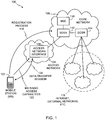
- the mobile communications network 100 includes an access network 104 and a core network 106.
- the access network 104 includes an access network interface 108 in communication with the mobile station 102 to enable the mobile station 102 to exchange information with the core network 106.
- the access network interface 108 can be implemented using a processor-based device or a controller such as, for example, a packet control unit (PCU) for a GSM enhanced radio access network (GERAN), a radio network controller (RNC) for a UMTS radio access network (UMTS RAN), or any other type of controller for any other type of access network.
- PCU packet control unit
- GERAN GSM enhanced radio access network
- RNC radio network controller
- UMTS RAN UMTS radio access network
- the core network 106 can be a GPRS core network or a core network of any other communication technology type.
- the core network 106 includes a mobile switching center (MSC) server 110, a serving GPRS support node (SGSN) 112, and a gateway GPRS support node (GGSN) 114.
- MSC mobile switching center
- SGSN serving GPRS support node
- GGSN gateway GPRS support node
- the SGSN 112 manages subscriber-specific data during subscriber sessions and the GGSN 114 establishes and maintains connections between the core network 106 and external packet data networks 116 (e.g., the Internet, private networks, etc.).
- packet data networks 116 e.g., the Internet, private networks, etc.
- the mobile station 102 registers with the core network 106 upon discovering the access network 104 by performing a registration process 118 using non-access stratum signaling. During the registration process 118, the mobile station 102 sends an initial communication including all or a subset of its radio access capabilities to the core network 106.
- the mobile station 102 may send an exhaustive list of its radio access capabilities to the core network 106, while in other example implementations, the mobile station 102 can send radio access capabilities relevant only to downlink data transfers (in which case uplink-relevant capability information can be communicated when the mobile station 102 subsequently requests the access network 104 to establish a data transfer session), or omitting capabilities which are exclusively applicable to uplink data transfers (e.g., the support of extended dynamic allocation (EDA)).
- EDA extended dynamic allocation
- the core network 106 can communicate the list of radio access capabilities received from the mobile station 102 to the access network interface 108 after the registration process 118 such as when initiating a downlink transfer.
- some or all of the indications of radio access capabilities sent by the mobile station 102 to the core network 106 are different from the radio access capability indications sent by the mobile station 102 to the access network 104 during signaling procedures to request resources for establishing uplink data transfers.
- Such indications of radio access capabilities sent during different events can differ either in scope (e.g., capabilities sent to the access network 104 may be those that are only applicable to uplink data transfers and/or capabilities sent to the core network 106 may omit such capabilities or may be exhaustive) or in format (e.g., the capabilities signaled to the core network 106 may use an first structural format in a message or information element, while capabilities signaled to the access network 104 may use a second structural format different from the first structural format).
- the mobile station 102 can subsequently, at one or more times while it is registered, request connections with the access network interface 108 to request the access network interface 108 to establish data transfer sessions between the mobile station 102 and the access network 104. For example, as shown in FIG. 1 , the mobile station 102 establishes a data transfer session 120 with the access network 104. During a process to establish the data transfer session 120 or after the data transfer session 120 has been established, the mobile station 102 sends mobile station (MS) radio access capabilities information 122 to the access network interface device 108.
- MS mobile station
- the mobile station 102 may send an exhaustive list of its capabilities to the access network 104 during the registration process 118 using non-access stratum signaling, when the mobile station 102 subsequently requests the data transfer session 120, it uses access stratum signaling to send to the access network 104 only the subset of the radio access capabilities that the mobile station 102 intends to use for the data transfer session 120. For example, if the data transfer session 120 is intended for a small data transfer, the MS radio access capabilities 122 communicated by the mobile station 102 to the access network interface 108 will indicate only those radio access capabilities relevant to small data transfers. In this manner, the mobile station 102 need not communicate the exhaustive list of its radio access capabilities every time it requests a data transfer session.
- access stratum signaling is latency critical and can occur relatively more frequently.
- reducing the subset of radio access capabilities sent by the mobile station 102 to the access network interface 104 while establishing data transfer sessions can improve the performance and efficiency of data transfer sessions between the mobile station 102 and the access network 104.
- the data transfer session 120 can be a small data transfer session, a machine-to-machine data transfer session, an uplink data transfer session, and/or any other type of data transfer session including any combination thereof.
- the mobile station 102 can establish the data transfer session 120 by requesting the access network 108 to establish a TBF in accordance with the example methods and apparatus disclosed herein to perform a small data transfer, a machine-to-machine data transfer, an uplink data transfer, etc.
- the example methods and apparatus disclosed herein facilitate signaling the MS radio access capabilities information 122 to the access network interface 108 using techniques that are relatively more efficient than known techniques.
- FIG. 2 depicts example signaling of a two-phase access procedure 200
- FIG. 3 depicts example signaling of a one-phase access procedure 300.
- the access procedures 200 and 300 can be used to establish a data transfer session (e.g., the data transfer session 120 of FIG. 1 ) with a GERAN.
- the mobile station 102 initiates the two-phase access procedure 200 by sending a channel request message 202 to the access network interface 108 via a random access channel (RACH) (or any other suitable available channel).
- RACH random access channel
- the access network interface 108 responds by sending an immediate assignment message 204 to the mobile station 102 via a common control channel (CCCH).
- the immediate assignment message 204 assigns a quantity (N) of blocks allocated on an uplink data channel for use by the mobile station 102 to send its radio access capabilities (e.g., the MS radio access capabilities information 122 of FIG. 1 ) to the access network interface device 108.
- the mobile station 102 then generates and sends a packet resource request (PRR) message 206 to the access network interface device 108.
- the mobile station 102 sends the PRR message 206 via a packet associated control channel (PACCH) using one of the blocks allocated by the access network interface device 108.
- the PRR message 206 includes a MS radio access capabilities IE including the radio access capabilities of the mobile station 102. Example implementations of the PRR message 206 are described below in connection with FIG. 4 .
- the mobile station 102 If additional space is required to communicate the radio access capabilities of the mobile station 102 to the access network interface device 108, the mobile station 102 generates and sends an additional MS radio access capabilities (AMSRAC) message 208 to the access network interface 108 via the PACCH.
- the AMSRAC message 208 includes another instance of the MS radio access capabilities IE with the additional radio access capabilities of the mobile station 102.
- the access network interface 108 can use the received capabilities of the mobile station 102 to allocate an uplink data channel based on the received radio access capabilities for use by the mobile station 102 during a data transfer session (e.g., the data transfer session 120 of FIG. 1 ).
- the access network interface 108 then communicates a packet uplink assignment message 210 to the mobile station 102 via a packet associated control channel (PACCH).
- PACCH packet associated control channel
- the packet uplink assignment message 210 indicates a data uplink channel allocated to the mobile station 102 for use during the data transfer session 120.
- the one-phase access procedure 300 of FIG. 3 enables allocation of a data uplink channel to the mobile station 102 without needing the mobile station 102 to send a PRR message to the access network interface device 108.
- the mobile station 102 sends a channel request message 302 to the access network interface 108 via a RACH (or any other available suitable channel).
- the mobile station 102 requests to perform a one-phase access procedure and can indicate its radio access capabilities.
- the amount of information that the mobile station 102 can include in the channel request message 302 to indicate its radio access capabilities may be relatively limited depending on the amount of space available in the channel request message 302.
- the access network interface 108 can determine whether to grant a one-phase access procedure or to require a two-phase access procedure. For example, the access network interface 108 can require a two-phase access procedure if it requires further radio access capabilities information from the mobile station 102.
- the access network interface 108 responds by sending an immediate assignment message 304 via a CCCH (or any other available suitable channel). If the access network interface 108 elects to grant the one-phase access procedure, the immediate assignment message 304 will indicate an allocation of an uplink data channel for use by the mobile station 102 to implement the data transfer session 120. In this manner, the mobile station 102 can immediately begin its data transfer.
- a CCCH or any other available suitable channel
- the immediate assignment message 304 will be substantially similar to the immediate assignment message 204 of FIG. 2 allocating a quantity (N) of blocks for use by the mobile station 102 to communicate further radio access capabilities.
- the mobile station 102 can communicate its radio access capabilities messages to the access network interface 108 using a PRR message 306 (substantially similar or identical to the PRR message 206 of FIG. 2 ) and optionally an AMSRAC message 308 (substantially similar or identical to the AMSRAC message 208 of FIG. 2 ) if necessary to communicate additional radio access capabilities that did not fit in the PRR message 306.
- the access network interface 108 may then send a packet uplink assignment message 310 (substantially similar or identical to the packet uplink assignment message 210 of FIG. 2 ).
- the access network interface 108 may elect to grant the one-phase access procedure but request a full or exhaustive listing of radio access capabilities from the mobile station 102.
- the immediate assignment message 304 allocates an uplink data channel to the mobile station 102, and the mobile station 102 communicates the requested radio access capabilities to the access network interface 108 in the PRR message 306 (and the AMSRAC message 308, if more space is required) via the allocated data channel.
- the access network interface 108 would not necessarily communicate the packet uplink assignment message 310, because the immediate assignment message 304 already allocated the uplink data channel to the mobile station 102.
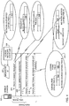
- FIG. 4 depicts different example configurations of example messages in accordance with the example methods and apparatus disclosed herein that can be used to communicate mobile station radio access capabilities during a data transfer setup procedure (e.g., the procedures 200 and/or 300 of FIGS. 2 and 3 ).
- a one-phase access typically involves exchanging a channel request message 402 and an immediate assignment message 408 between the mobile station 102 and the access network interface 108.
- a two-phase access typically involves exchanging the channel request message 402, the immediate assignment message 408, a packet resource request message 412, and, when additional space is required, an additional MS radio access capabilities message 418.
- the messages are shown in FIG.
- FIG. 4 shows the different information fields in connection with particular types of messages, in other example implementations, the information fields may be provided in others of the messages illustrated in FIG. 4 or may be provided in other types of messages not shown in FIG. 4 . Thus, the placements of the information fields are shown by way of example in FIG. 4 in connection with particular messages; however, such information fields may additionally or alternatively be placed in other messages.
- the access network interface 108 can broadcast system information (SI) messages 401 to communicate the radio access capabilities supported by the access network 104 ( FIG. 1 ) via a broadcast control channel (BCCH).
- SI system information
- the broadcast SI messages 401 can be configured to include a network-supported capabilities field 410 (or fields) in which the access network interface 108 can indicate the radio access capabilities supported by the access network 104.
- the broadcast SI message 401 may also be used to indicate whether the access network 104 supports only specific use-type capability structures (e.g., the MTC capabilities structure 806, but not the SDT capabilities structure 810 of FIG. 8 ).
- the network-supported capabilities information can then be used by the mobile station 102 to determine whether it can connect to the access network 104 for a particular use-type data transfer session. Additionally or alternatively, the mobile station 102 can use the network-supported capabilities to filter its radio access capabilities to identify those that are supported by the access network 104 and, thus, communicate only those capabilities to the access network interface device 108. Additionally or alternatively, the access network interface 108 may communicate the network-supported capabilities field(s) 410 to the mobile station 102 via the immediate assignment message 408 or any other message suitable for this purpose.
- the mobile station 102 uses a channel request message 402 during a two-phase access procedure (e.g., the two-phase access procedure 200 of FIG. 2 ) to indicate a quantity (N) of blocks required for the mobile station 102 to send its radio access capabilities to the access network interface device 108.
- a two-phase access procedure e.g., the two-phase access procedure 200 of FIG. 2
- the channel request message 402 can be defined to include a requested block quantity field 404 to indicate the quantity (N) of blocks on an uplink data channel that the mobile station 102 intends to use to send its capabilities.
- the mobile station 102 may determine a quantity (N) of blocks value for the requested block quantity field 404 based on a quantity of data or data size required to send the radio access capabilities information (e.g., radio access capabilities relevant for a particular type of use of a data transfer session or radio access capabilities that are commonly supported by the mobile station 102 and the access network 104, which may be for a particular type of use of a data transfer session) of the mobile station 102 to the access network interface 108.
- the radio access capabilities information e.g., radio access capabilities relevant for a particular type of use of a data transfer session or radio access capabilities that are commonly supported by the mobile station 102 and the access network 104, which may be for a particular type of use of a data transfer session
- the channel request message 402 can include one or more capabilities configuration ID field(s) 406.
- the mobile station 102 can use the one or more capabilities configuration ID field(s) 406 of the channel request message 402 during a one-phase access procedure (e.g., the one-phase access procedure 300 of FIG. 3 ) to send one or more radio access capabilities configuration IDs (e.g., RAC configuration IDs 702 and 706 of FIGS. 7A and 7B ) pre-defined to represent a particular radio access capabilities configuration or configurations of the mobile station 102.
- the pre-defined capabilities configuration IDs can be defined by industry standards, network-assigned, or network-negotiated such that any access network could determine the capabilities configuration of any mobile station based on a capabilities configuration IDs.
- the mobile station 102 uses a PRR message 412 to send its radio access capabilities in a MS radio access capabilities IE field 414 structured or arranged as shown in FIGS. 5 and 8A-8C .
- the mobile station 102 can set an AMSRAC message indicator 416 in the PRR message 412 to indicate that the mobile station 102 will send an AMSRAC message 418 including its additional radio access capabilities using another instance of the MS radio access capabilities IE field 414.
- an example information arrangement 500 of the PRR message 412 shows the arrangement of the MS radio access capabilities IE field 414 and the AMSRAC message indicator 416 in the content of the PRR message 412.
- the MS radio access capabilities IE field 414 includes a coding form field 420 and a capabilities structure field 422 to include capabilities information from radio access capabilities structures.
- the radio access capabilities structures can be use-type structures, each of which indicates radio access capabilities associated with or relevant to a particular type of use (e.g., a machine-to-machine communication session, an uplink-only communication session, a small data transfer session, a general or multi-use communication session) for a data transfer session.
- values stored in the coding form field 420 indicate which type of radio access capabilities structures is reflected in the capabilities structure field 422.
- the coding form field 420 can serve as a key for the access network interface 108 to identify the structural format used to represent radio access capabilities information in the capabilities structure field 422. That is, for each form code value (e.g., use-type codes 602 of FIG. 6 ) that can be stored in the coding form field 420, a different format structure can be used to store radio access capabilities in the capabilities structure field 422 to accommodate the specific types of capabilities applicable for each type of use for a data transfer session.
- form code value e.g., use-type codes 602 of FIG. 6
- FIG. 6 is a table 600 showing example use-type codes 602 that can be used in connection with the PRR message 412 and the AMSRAC message 418 of FIGS. 4 and 5 (or the PRR messages 206 and 306 and the AMSRAC messages 208 and 308 of FIGS. 2 and 3 ) to identify respective use-type radio access capabilities structures encoded in the PRR message 412.
- the use-type codes 602 are shown as sequentially numbered values, each of which is indicative of a respective use-type radio access capabilities structure 604.
- the mobile station 102 can write or insert the use-type code 602 in the coding form field 420 of the MS radio access capabilities IE 414 shown in FIG. 4 to identify the type of radio access capability structure coding in the capabilities structure field 422.
- the use-type codes 602 and corresponding use-type radio access capabilities structures 604 may be implemented using the structures shown in FIGS. 8A-8C .
- the use-type radio access capabilities structures 604 are listings, sets, subsets, or groupings of capabilities referred to as a type A structure 604a, a type B structure 604b, a type C structure 604c, and a type D structure 604d.
- the type A structure 604a can be a general capabilities structure indicative of radio access capabilities to establish data transfer sessions between the mobile station 102 and the access network interface 108 of FIGS. 1-4 when a particular type of use for the data transfer is not specified or does not pertain to any of the other radio access capabilities structures.
- the type B structure 604b can be, for example, a machine type communications (MTC) structure indicative of radio access capabilities relevant to (or which may be relevant to) data transfer sessions for use in machine-to-machine data transfers.
- the type C structure 604c can be, for example, an uplink communications structure indicative of radio access capabilities relevant to data transfer sessions for use in uplink-only data transfers.
- the types 604a, 604b, and 604d can provide capabilities information related to uplink and downlink communications (e.g., uplink/downlink capabilities for MTC or SDT data transfers)
- the type C structure 604c can be indicative of capabilities related only to uplink communications to establish uplink-specific data transfer sessions.
- the type D structure 604d can be, for example, a SDT structure indicative of radio access capabilities applicable to small data transfer sessions.
- the mobile station 102 can send one of the use-type codes 602 and a corresponding one of the use-type radio access capabilities structures 604 when it intends one type of use for a data transfer session.
- the use-type codes 602 and corresponding use-type radio access capabilities structures 604 can advantageously be used in the example methods and apparatus disclosed herein to minimize the quantity of radio access capabilities sent by the mobile station 102 to the access network interface 108 to only relevant capabilities when requesting a data transfer session (e.g., the data transfer session 120 of FIG. 1 ).
- the use-type codes 602 can also advantageously be used in the example methods and apparatus disclosed herein to facilitate or enable future expansion or future changes of the types of capabilities that can be communicated in the MS radio access capabilities IE 414 of FIG. 4 to accommodate capabilities developed or standardized in the future.
- a capability when a capability is added to (or removed from) one of the use-type radio access capabilities structures 604, its corresponding use-type code 602 can remain unchanged while identifying the updated use-type radio access capabilities structure 604 in the capabilities structure field 422 of FIG. 4 .
- subsequently added use-type codes 602 can be specified to identify different use-type capability structures that are supported or standardized in the future.
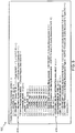
- FIGS. 7A and 7B depict tables 700 and 701 showing example pre-defined radio access capability configurations that may be used to indicate the capabilities of the mobile station 102.
- the table 700 shows radio access capabilities (RAC) configuration IDs 702, each of which is used to indicate a respective configuration of radio access capabilities settings 704 for GPRS capability subsets.
- RAC configuration ID 706 is used to indicate a respective configuration of radio access capabilities settings 708 for DTM capability subsets.
- Each of the radio access capabilities settings 704 and 708 is a listing, set, subset, or grouping of different types of radio access capabilities (e.g., two or more of a multislot classes capabilities type, a supported modulation schemes capabilities type, a packet switched handover capabilities type, a DTM capabilities type, a power class capabilities type, a latency reduction capabilities type, and/or any other suitable types of radio access capabilities) that can be pre-defined in accordance with industry standards, assigned by the access network 108, or negotiated between the mobile station 102 and the access network interface 108. In this manner, the mobile station 102 can inform the access network interface 108 of particular radio access capabilities settings by communicating one or more of the RAC configuration IDs 702 and/or 706 corresponding to its radio access capabilities.
- a multislot classes capabilities type e.g., a supported modulation schemes capabilities type, a packet switched handover capabilities type, a DTM capabilities type, a power class capabilities type, a latency reduction capabilities type, and/or any other suitable types
- the mobile station 102 need not explicitly communicate all of its radio access capabilities but can instead exclude from (or not include in) a capabilities signaling message (e.g., the channel request message 402 or the PRR message 412 of FIG. 4 ) the individual radio access capabilities information indicated by the one or more RAC configuration IDs 702 and 706.
- a capabilities signaling message e.g., the channel request message 402 or the PRR message 412 of FIG. 4
- the RAC configuration IDs 702 and 706 can be advantageously used in connection with the one-phase access procedure 300 of FIG. 3 because each RAC configuration ID 702 and 706 requires only minimal space in a message (e.g., in the channel request message 302) to indicate radio access capabilities of the mobile station 102.
- the mobile station 102 can communicate one or more of the RAC configuration IDs 702 and 706 in the capabilities configuration ID field(s) 406 of the channel request message 402 of FIG. 4 .
- the RAC configuration IDs 702 and 706 can be advantageously used to reduce or eliminate the need to re-convey capabilities information during the same signaling procedure (e.g., the signaling procedures 200 and 300 of FIGS.
- communicating one or more of the RAC configuration IDs 702 and 706 from the mobile station 102 to the access network interface 108 once in the channel request message 402 would be sufficient for the access network interface 108 to establish a data transfer session for the mobile station 102 without requiring the mobile station 102 to re-convey explicit indications of its capabilities via the packet resource request message 412 or any other subsequent message.
- the RAC configuration IDs 702 and 706 disclosed herein can be advantageously communicated in a payload-carrying data packet via a normal burst (e.g., a GSM normal burst via any data channel).
- a normal burst e.g., a GSM normal burst via any data channel.
- the example methods and apparatus disclosed herein can be used to communicate the RAC configuration IDs 702 and 706 from the mobile station 102 to the access network interface 108 using any data packet without needing to use a channel request message (e.g., the channel request messages 202, 302, and 402 of FIGS. 2-4 ).
- a channel request message e.g., the channel request messages 202, 302, and 402 of FIGS. 2-4 .
- the RAC configuration IDs 702 and 706 can be advantageously used to inform access networks of radio access capabilities of mobile stations via channel request messages or payload-carrying data packets, in other example implementations, the RAC configuration IDs 702 and 706 can alternatively or additionally be communicated in the PRR message 412 and/or the AMSRAC message 418 of FIG. 4 .
- the RAC configuration IDs 702 and 706 can be pre-defined in a hierarchical configuration such that ones of the RAC configuration IDs 702 and 706 having higher values (or lower-values in a numerically descending hierarchy) implicitly indicate that capabilities corresponding to lower valued (or higher valued in a numerically descending hierarchy) ones of the RAC configuration IDs 702 and 706 are also supported by a mobile station.
- the mobile station 102 can send only a single one of the RAC configuration IDs 702 and 706 to inform the access network interface 108 that the mobile station 102 supports the capabilities indicated by that one of the RAC configuration IDs 702 and 706 and all of the capabilities indicated by the lower-valued ones of the RAC configuration IDs 702 and 706, but that were not explicitly communicated by the mobile station 102.
- such hierarchies may be pre-defined (or allocated by the access network 104) such that higher-valued (or lower-valued in a numerically descending hierarchy) ones of the RAC configuration IDs 702 and 706 implicitly indicate support of capabilities corresponding to the lower-valued (or higher-valued in a numerically descending hierarchy) ones of the RAC configuration IDs 702 and 706 because support for the higher-valued capabilities requires support for the lower-valued capabilities.
- the radio access capabilities settings 704 and 708 can be defined or configured based on different industry standards including radio access technology standards.
- the radio access capabilities settings 704 of FIG. 7A are shown as having first, second, and third GPRS capability settings 704a, 704b, and 704c and the radio access capabilities settings 708 of FIG. 7B are shown as having first and second DTM capability settings 708a and 708b.
- each of the GPRS capability settings 704a, 704b, and 704c indicates different capability settings with respect to the GPRS radio access technology capabilities subset of the table 700 (e.g., different frequency bands, different multislot classes, different shift keying, different timing, etc.).
- each of the DTM capability settings 708a and 708b indicates different capability settings with respect to DTM communications.
- other types of radio access capabilities subsets can additionally or alternatively be implemented for features or capability types other than GPRS and DTM.
- the mobile station 102 can send a complete listing of its capabilities (e.g., using a general capabilities structure 804 of FIGS. 8A and 8B ) to the access network interface 108.
- the access network interface 108 can then send the RAC configuration IDs 702 and 706 corresponding to different radio access capabilities settings configurations that the mobile station 102 is capable of supporting. In this manner, the mobile station 102 can use the RAC configuration IDs 702 and 706 assigned by the access network 104 when establishing subsequent data transfer sessions.
- each of the radio access capabilities settings 704 and 708 can be use-type configurations.
- one of the RAC configuration IDs 702 can be indicative of MTC radio access capabilities of the mobile station 102 while other ones of the RAC configuration IDs 702 can be indicative of uplink radio access capabilities and/or small data transfer capabilities of the mobile station 102.
- the mobile station 102 when the mobile station 102 intends to use a data transfer session (e.g., the data transfer session 120 of FIG. 1 ) for a particular type of use, the mobile station 102 can indicate its radio access capabilities to the access network interface 108 using a respective one of the RAC configuration IDs 702 and/or 706.
- the RAC configuration IDs 702 and 706 can be indicative of radio access technologies for respective technology types (e.g., capabilities of respective frequency bands) and/or can be indicative of device classes associated with, for example, different MTC or SDT capabilities.
- the mobile station 102 intends to communicate over a data transfer session (e.g., the data transfer session 120 of FIG. 1 ) using a particular type of access technology or device class capabilities, the mobile station 102 can indicate its radio access capabilities for the access technology type to the access network interface 108 using a respective one of the RAC configuration IDs 702 and 706.
- the mobile station 102 can send one of the RAC configuration IDs 702 and/or 706 to indicate a single one of the radio access capabilities settings 704 and/or 708. In other instances, the mobile station 102 can send two or more of the RAC configuration IDs 702 and/or 706 to indicate multiple ones of the radio access capabilities settings 704 and/or 708.
- the mobile station 102 can send two of the RAC configuration IDs 702 related to GPRS capabilities (e.g., send GPRS#01 and GPRS#02) or the mobile station 102 can send one or more of the RAC configuration IDs 702 and one or more of the RAC configuration IDs 706 to indicate GPRS and DTM capabilities (e.g., send GPRS#01 and DTM#02).
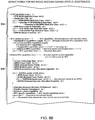
- FIGS. 8A-8C depict example structural formats that can be used to send radio access capabilities information of the mobile system 102 ( FIGS. 1-4 ) to the access network interface 108 ( FIGS. 1-4 ) in the MS radio access capabilities IE 414 ( FIG. 4 ) during the example signaling exchanges of FIGS. 2-4 .
- use-type radio access capabilities structures shown in FIGS. 8A-8C can be advantageously used to limit the multislot classes, switching times, and packet switched handover capabilities indicated to the access network 104 as supported by the mobile station 102 to only those capabilities relevant to a requested data transfer session.
- the mobile station 102 implicitly or expressly informs the access network 104 that the radio access capabilities information indicated thereby is not complete (e.g., support for one or more radio access capabilities may be implicit in the use of some or any of the use-type radio access capabilities structures). Additionally or alternatively, the mobile station 102 informs (e.g., implicitly through the use of some or any of the use-type radio access capabilities structures shown in FIGS. 8A-8C ) the access network 104 that further radio access capabilities of the mobile station 102 can be obtained from the core network 106 ( FIG. 1 ). Also, some of the use-type radio access capabilities structures can enable or facilitate omitting capabilities not related to GSM communications.
- an MS radio access capabilities value part structure 802 specifies example formats for encoding the use-type codes 602 of FIG. 6 in the coding form field 420 of the MS radio access capabilities IE 414 of FIG. 4 .
- a general capabilities structure 804 of FIGS. 8A and 8B specifies example formats for encoding an exhaustive or complete listing of radio access capabilities of the mobile station 102 in the capabilities structure field 422 of the MS radio access capabilities IE 414 of FIG. 4 .
- the general capabilities structure 804 can be used to implement the type A structure 604a of FIG. 6 .
- the general radio access capabilities can be used to establish a data transfer session between the mobile station 102 and the access network interface device 108 when a particular type of use for the data transfer session is not indicated or does not pertain to any other available radio access capabilities structure of the mobile station 102.
- a MTC capabilities structure 806 shown in FIG. 8B specifies example formats for encoding MTC radio access capabilities of the mobile station 102 in the capabilities structure field 422 of the MS radio access capabilities IE 414 of FIG. 4 .
- the MTC capabilities structure 806 can be used to implement the type B structure 604b of FIG. 6 to establish data transfer sessions for use in machine-to-machine data transfers.
- An uplink capabilities structure 808 shown in FIG. 8C specifies example formats for encoding uplink-specific radio access capabilities of the mobile station 102 in the capabilities structure field 422 of the MS radio access capabilities IE 414 of FIG. 4 .
- the uplink capabilities structure 808 can be indicative of capabilities related only to uplink communications to establish uplink-specific data transfer sessions.
- the uplink capabilities structure 808 can be used to implement the type C structure 604c of FIG. 6 to establish data transfer sessions for use in uplink data transfers.
- An SDT capabilities structure 810 shown in FIG. 8C specifies example formats for encoding small data transfer radio access capabilities of the mobile station 102 in the capabilities structure field 422 of the MS radio access capabilities IE 414 of FIG. 4 .
- the SDT capabilities structure 810 can be used to implement the type D structure 604d of FIG. 6 to establish data transfer sessions for use in small data transfers. For purposes of brevity, some radio access capabilities information of the SDT capabilities structure 810 is not shown in detail.
- An additional access technologies structure 812 shown in FIG. 8C specifies whether other access technology types (e.g., other frequency bands) are supported by the mobile station 102.
- the additional access technologies structure 812 can be encoded in the capabilities structure field 422 of the MS radio access capabilities IE 414 of FIG. 4 in connection with any of the capabilities structures 804, 806, 808, or 810 to indicate different access technology types for which the mobile station 102 supports the radio access capabilities of the capabilities structures 804, 806, 808, or 810.
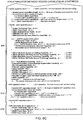
- FIGS. 9-13 depict example flow diagrams representative of example processes that may be implemented using hardware and/or computer readable instructions that may be used to communicate radio access capabilities of a mobile station (e.g., the mobile station 102 of FIGS. 1-4 ) to an access network (e.g., the access network 104 of FIG. 1 ).
- the example operations of FIGS. 9-13 may be performed using a processor, a controller and/or any other suitable processing device.
- the example operations of FIGS. 9-13 may be implemented using coded instructions stored on a tangible medium such as a flash memory, a read-only memory (ROM) and/or random-access memory (RAM) associated with a processor (e.g., the processor 1402 of FIG. 14 ).
- FIGS. 9-13 may be implemented using any combination(s) of application specific integrated circuit(s) (ASIC(s)), programmable logic device(s) (PLD(s)), field programmable logic device(s) (FPLD(s)), discrete logic, hardware, firmware, etc. Also, some or all of the example operations of FIGS. 9-13 may be implemented manually or as any combination(s) of any of the foregoing techniques, for example, any combination of firmware, software, discrete logic and/or hardware. Further, although the example operations of FIGS. 9-13 are described with reference to the flow diagrams of FIGS. 9-13 , other methods of implementing the operations of FIGS. 9-13 may be employed.
- any or all of the example operations of FIGS. 9-13 may be performed sequentially and/or in parallel by, for example, separate processing threads, processors, devices, discrete logic, circuits, etc.
- FIGS. 9-13 are described in connection with the example signaling diagram of FIG. 400. Some implementations of the flow diagrams can be implemented using two-phase access procedures such as the two-phase access procedure 200 of FIG. 2 , while other implementations of the flow diagrams can be implemented using one-phase access procedures such as the one-phase access procedure 300 of FIG. 3 .
- FIG. 9 is a flow diagram representative of an example process that may be implemented using machine readable instructions to select and communicate radio access control information of the mobile station 102 of FIGS. 1-4 .
- the mobile station 102 registers with the core network 106 of FIG. 1 (block 901).
- the mobile station 102 can perform the registration process 118 ( FIG. 1 ) using non-access stratum signaling and send an exhaustive list of its radio access capabilities or a list of downlink radio access capabilities to the core network 106 ( FIG. 1 ).
- the mobile station 102 When the mobile station 102 intends to perform a data transfer, the mobile station 102 sends the channel request message 402 of FIG. 4 to the access network interface 108 (block 902).
- the mobile station 102 requests in the channel request message 402 to perform a two-phase access procedure (e.g., the two-phase access procedure 200 of FIG. 2 ).
- the mobile station 102 may also use the channel request message 402 to request a quantity (N) of blocks to be allocated on an uplink data channel to it by the access network 104 to use for communicating its radio access capabilities.
- N a quantity of blocks to be allocated on an uplink data channel to it by the access network 104 to use for communicating its radio access capabilities.
- Such an allocation of blocks can be requested using, for example, the requested block quantity field 404 of FIG. 4 .
- the mobile station 102 may determine a quantity (N) of blocks value for the requested block quantity field 404 based on a quantity of data or data size required to send the radio access capabilities information (e.g., radio access capabilities relevant for a particular type of use of a data transfer session or radio access capabilities that are commonly supported by the mobile station 102 and the access network 104, which may be for a particular type of use of a data transfer session) of the mobile station 102 to the access network interface 108.
- the radio access capabilities information e.g., radio access capabilities relevant for a particular type of use of a data transfer session or radio access capabilities that are commonly supported by the mobile station 102 and the access network 104, which may be for a particular type of use of a data transfer session
- the mobile station 102 receives the immediate assignment message 408 from the access network interface 108 (block 904).
- the immediate assignment message 408 indicates a quantity (N) of blocks allocated to the mobile station 102 on an uplink data channel to communicate its radio access capabilities to the access network 104.
- the quantity (N) of blocks may be a quantity requested by the mobile station 102, while in other example implementations, the quantity (N) of blocks may be allocated by the access network 104 regardless of a particular quantity requested by the mobile station 102.
- the mobile station 102 selects its mobile station radio access capabilities information to send to the access network interface 108 (block 906).
- the mobile station 102 can use any of the techniques described above in connection with FIGS. 4-7 and 8A-8C to select the radio access capabilities information.
- the example flow diagrams of FIGS. 10-12 described below can be used to implement block 906.
- the mobile station 102 generates the mobile station radio access capabilities information element (MS RAC IE) 414 of FIGS. 4 and 5 for the PRR message 412 of FIG. 4 (block 908).
- the mobile station 102 then generates the PRR message 412 of FIG. 4 to include the MS RAC IE 414 (block 910).
- the mobile station 102 determines whether it needs additional space for additional radio access capabilities information (block 912). For example, the mobile station 102 may require further space than available in the PRR message 412 to communicate its capabilities. If the mobile station 102 determines that it does not need additional space (block 912), the mobile station 102 sends the PRR message 412 to the access network interface 108 (block 914).
- the mobile station 102 determines that it needs additional space (block 912)
- the mobile station 102 sets a value in the AMSRAC indicator field 416 ( FIG. 4 ) of the PRR message 412 (block 916) to indicate that it will communicate additional radio access capability information in the AMSRAC message 418 of FIG. 4 to the network access interface device 108.
- the mobile station 102 generates another instance of the MS RAC IE 414 with the additional capabilities for the AMSRAC message 418 (block 918).
- the mobile station 102 then generates the AMSRAC message 418 (block 920) including the additional instance of the MS RAC IE 414 with the additional radio access capabilities.
- the mobile station 102 sends the PRR message 412 and the AMSRAC message 418 to the access network interface 108 (block 922).
- the access network interface 108 can be configured to decode and use the capabilities information in the PRR message 412 and the AMSRAC message 418 in a number of ways. For example, the access network interface 108 can begin decoding and using the access capabilities in the PRR message 412 to begin allocating an uplink data channel prior to receiving the AMSRAC message 418 and then decode the AMSRAC message 418 to finish allocating and configuring the uplink data channel in accordance with the radio access capabilities indicated by the mobile station 102. Alternatively, the access network interface 108 can wait until it has received both the PRR message 412 and the AMSRAC message 418 before decoding and using the radio access capabilities information to allocate and configure the uplink data channel for the mobile station 102.
- the mobile station 102 After the mobile station 102 sends the PRR message 412 and the AMSRAC message 418 at block 922 or after the mobile station 102 sends the PRR message 412 at block 914 without setting the AMSRAC indicator field 416, the mobile station 102 receives a packet uplink assignment message (e.g., the packet uplink assignment message 210) (block 924) from the access network interface device 108.
- the packet uplink assignment message indicates an uplink data channel allocated to the mobile device 102 via which to perform the data transfer session 120 ( FIG. 1 ).
- the access network interface 108 allocates and configures the uplink data channel in accordance with the radio access capabilities provided by the mobile station 102.
- the example process of FIG. 9 then ends.
- FIG. 10 is a flow diagram representative of an example process that may be implemented using machine readable instructions to select radio access capabilities information of the mobile station 102 of FIGS. 1-4 .
- the example process of FIG. 10 can be used to implement block 906 of FIG. 9 .
- radio access capabilities are selected using the use-type codes 602 of FIG. 6 and their associated use-type radio access capabilities structures 604.
- the mobile station 102 determines whether and which of the use-type coding forms (e.g., the use-type codes 602 and associated capabilities structures 604 of FIG. 6 ) are supported by the access network 104 (block 1002).
- the access network 104 may communicate an indication of support for such coding forms in the broadcast SI message 401 ( FIG. 4 ) (or in any other suitable message).
- the broadcast SI message 401 may also be used to indicate whether the access network 104 supports only some (but not all) use-type capability structures (e.g., the access network 104 supports the MTC capabilities structure 806, but not the SDT capabilities structure 810 of FIG. 8 ) and their identities.
- networks could be configured to have default support for the general capabilities structure 804 ( FIGS. 8A and 8B ) and networks that support optimized capabilities for MTC and/or SDT could additionally support the MTC capabilities structure 806 and/or the SDT capabilities structure 810. Additionally or alternatively, particular use-type capabilities could be implicitly supported by an access network on specific channel types supported by the access network. In some instances, some types of channels that can be allocated by access networks may support only MTC communications, while other types of channels may support only SDT communications.
- the mobile station 102 selects the corresponding type of use for the data transfer session it is establishing (block 1004).
- Example types of uses may be a machine-to-machine data transfer use, an uplink data transfer use, a small data transfer use, or any other type of use.
- the mobile station 102 selects a MS radio access capabilities structure (e.g., one of the use-type radio access capabilities structures 604 of FIG. 6 or structures 804, 806, 808, and 810 of FIG. 8 ) and a corresponding use-type code (e.g., one of the use-type codes 602 of FIG. 6 ) pertaining to the type of use for the data transfer session (block 1006).
- the mobile station 102 applies a corresponding formatting of the selected MS radio access capabilities structure to the structural format of the capabilities structure field 422 of the MS radio access capabilities IE 414 of FIG. 4 (block 1008). In this manner, the mobile station 102 can encode the MS radio access capabilities IE 414 at block 908 of FIG. 9 with one of the use-type codes 602 and the corresponding radio access capabilities information in accordance with a structural format of the selected MS radio access capabilities structure.
- the mobile station 102 can select radio access capability information based on legacy capabilities formats (block 1010).
- the mobile station 102 can then encode the radio access capabilities information in the MS radio access capabilities IE 414 at block 908 of FIG. 9 in accordance with a legacy structural format.
- the example process of FIG. 10 ends and/or returns control to a calling function or process such as the example process of FIG. 9 .
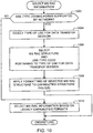
- FIG. 11 is a flow diagram representative of another example process that may be implemented using machine readable instructions to select radio access capabilities information of the mobile station 102 of FIGS. 1-4 .
- the example process of FIG. 11 can be used to implement block 906 of FIG. 9 or block 1302 of FIG. 13 .
- radio access capabilities are selected using the RAC configuration IDs 702 and/or 706 of FIGS. 7A and 7B .
- the mobile station 102 selects one or more RAC configuration ID(s) 702, 706 (block 1102). As discussed above in connection with FIGS. 7A and 7B , the RAC configuration IDs 702, 706 correspond to different ones of the radio access capabilities settings 704, 708. In this manner, the mobile station 102 can insert the selected RAC configuration ID(s) 702,706 in the channel request message 402 or the PRR message 412 of FIG. 4 to indicate its capabilities to the access network 104.
- the example process of FIG. 11 ends and/or returns control to a calling function or process such as the example process of FIG. 9 or the example process of FIG. 13 .
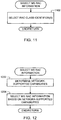
- FIG. 12 is a flow diagram representative of another example process that may be implemented using machine readable instructions to select radio access capability information of the mobile station 102 of FIGS. 1-4 .
- the example process of FIG. 12 can be used to implement block 906 of FIG. 9 .
- radio access capabilities are selected based on radio access capabilities supported by the access network 104.
- the mobile station 102 determines which radio access capabilities are supported by the access network 104 (block 1202). For example, the mobile station 102 can receive the broadcast SI messages 401 ( FIG. 4 ) from the access network interface 108 indicating the radio access capabilities that are supported by the access network 104. For example, the access network interface 108 can indicate such supported capabilities using the network-supported capabilities field(s) 410 of FIG. 4 . The mobile station 102 then selects its radio access capabilities (using, for example, one or more of the techniques disclosed herein) based on the network-supported capabilities (block 1204). The example process of FIG. 12 ends and/or returns control to a calling function or process such as the example process of FIG. 9 .
- FIG. 13 is a flow diagram representative of an example process that may be implemented using machine readable instructions to implement an example radio access capabilities signaling exchange in which the mobile station 102 requests a one-phase access procedure (e.g., the one-phase access procedure 300 of FIG. 3 ).
- the mobile station 102 registers with the core network 106 of FIG. 1 (block 1301).
- the mobile station 102 can perform the registration process 118 ( FIG. 1 ) using non-access stratum signaling and send an exhaustive list of its radio access capabilities or a list of downlink radio access capabilities to the core network interface 106 ( FIG. 1 ).
- the mobile station 102 selects its radio access capabilities information (block 1302) to indicate to the access network 104.
- the mobile station 102 selects radio access capabilities based on the RAC configuration IDs 702 and/or 706 of FIGS. 7A and 7B as described above in connection with FIG. 11 . In this manner, the mobile station 102 can communicate its radio access capabilities to the access network 104 using a relatively small quantity of bits in the channel request message 402 ( FIG. 4 ).
- the mobile station 102 generates the channel request message 402 (block 1304).
- the mobile station 102 includes the mobile station radio access capabilities information selected at block 1302 and a request to establish a data transfer session using a one-phase access procedure (e.g., the one-phase access procedure 300 of FIG. 3 ).
- the mobile station 102 can set a selected one or more of the RAC configuration IDs 702, 706 in the capabilities configuration ID field(s) 406 ( FIG. 4 ) of the channel request message 402.
- the mobile station 102 sends the channel request message 402 to the access network interface 108 (block 1306).
- the mobile station 102 receives the immediate assignment message 408 from the access network interface 108 (block 1312).
- the immediate assignment message 408 indicates an uplink data channel allocated for use by the mobile station 102 to perform the data transfer session 120 ( FIG. 1 ).
- the uplink data channel is allocated and configured in accordance with the radio access capabilities provided by the mobile station 102.
- the access network 104 may grant the one-phase access procedure requested by the mobile station 102, but will require further radio access capabilities information from the mobile station 102 (e.g., a full or exhaustive listing of radio access capabilities of the mobile station 102). If the mobile station 102 determines that the access network 104 has not requested further radio access capabilities information from the mobile station 102 (block 1314), then the data transfer session 120 is established between the mobile station 102 and the access network 104 (based on a one-phase access procedure), and the example process of FIG. 13 ends.
- further radio access capabilities information e.g., a full or exhaustive listing of radio access capabilities of the mobile station 102
- the mobile station 102 determines that the access network 104 has requested further radio access capabilities information from the mobile station 102 (block 1314)
- the mobile station 102 sends the further radio access capabilities information on the allocated data channel using a PRR message (e.g., the PRR message 412 of FIG. 4 ) or PRR and AMSRAC messages (the PRR message 412 and the AMSRAC message 418 of FIG. 4 ) (block 1316).
- the mobile station 102 may use the PRR message 412 and the AMSRAC message 418 when the PRR message 412 does not provide sufficient space to communicate all of the requested radio access capabilities to the access network 104.
- block 1316 may be implemented using operations similar or identical to the operations described above in connection with blocks 906, 908, 910, 912, 914, 916, 918, 920, and 922 of FIG. 9 .
- the example process of FIG. 13 then ends.
- the mobile station 102 includes a processor 1402 that may be used to control the overall operation of the mobile station 102.
- the processor 1402 may be implemented using a controller, a general purpose processor, a digital signal processor, dedicated hardware, or any combination thereof.
- the example mobile station 102 also includes a FLASH memory 1404, a random access memory (RAM) 1406, and an expandable memory interface 1408 communicatively coupled to the processor 1402.
- the FLASH memory 1404 can be used to, for example, store computer readable instructions and/or data.
- the FLASH memory 1404 can be used to store one or more of the data structures of FIGS. 5-7 and 8A-8C .
- the RAM 1406 can also be used to, for example, store data and/or instructions.
- the mobile station 102 is also provided with an external data I/O interface 1410.
- the external data I/O interface 1410 may be used by a user to transfer information to and from the mobile station 102 through a wired medium.
- the mobile station 102 is provided with a wireless communication subsystem 1412 to enable wireless communications with wireless networks such as mobile communication networks, cellular communications networks, wireless local area networks (WLANs), etc.
- wireless networks such as mobile communication networks, cellular communications networks, wireless local area networks (WLANs), etc.
- the mobile station 102 is provided with a speaker 1414, a microphone 1416, a display 1418, and a user input interface 1420.
- the display 1418 can be an LCD display, an e-paper display, etc.
- the user input interface 1420 could be an alphanumeric keyboard and/or telephone-type keypad, a multi-direction actuator or roller wheel with dynamic button pressing capability, a touch panel, etc.
- the mobile station 102 is also provided with a real-time clock (RTC) 1422 to track dates and a current time of day and/or to implement time-based and/or date-based operations.
- RTC real-time clock
- the mobile station 102 is a battery-powered device and is, thus, provided with a battery 1424 and a battery interface 1426.
Claims (15)
- Procédé pour communiquer les capacités d'un dispositif, comprenant :- l'envoi d'une demande à un réseau (902, 922), la demande demandant une quantité de blocs pour une communication à allouer pour une utilisation par une station mobile, la quantité de blocs étant déterminée sur la base d'une taille de données pour identifier des capacités d'accès radio de la station mobile ;- la réception d'une allocation de la quantité de blocs en provenance du réseau (904, 924) ; et- l'envoi d'informations de capacité d'accès radio de la station mobile via les blocs alloués (604, 704, 708).
- Procédé selon la revendication 1, dans lequel la demande est un message de demande de canal envoyé par la station mobile au réseau, dans lequel l'allocation de la quantité de blocs est reçue au niveau de la station mobile dans un message d'assignation, et dans lequel les informations de capacité d'accès radio de la station mobile sont envoyées au réseau via un canal de contrôle associé.
- Procédé selon la revendication 1, dans lequel la quantité de blocs est demandée par la station mobile en envoyant une valeur de quantité dans un message de demande de canal.
- Procédé selon la revendication 1, dans lequel l'envoi des informations de capacité d'accès radio de la station mobile au réseau comprend l'envoi des informations de capacité d'accès radio au cours d'un processus d'établissement de flux de blocs temporaire.
- Procédé selon la revendication 1, dans lequel les capacités d'accès radio se rapportent à un type spécifique d'utilisation par la station mobile pour la session de transfert de données.
- Procédé selon la revendication 1, dans lequel la quantité de blocs est déterminée sur la base de capacités d'accès radio qui sont supportées par le réseau et la station mobile.
- Procédé selon la revendication 1, dans lequel l'envoi des informations de capacité d'accès radio de la station mobile au réseau se produit après que la station mobile s'enregistre auprès d'un réseau coeur du réseau au cours d'un processus d'enregistrement, et dans lequel tout en s'enregistrant auprès du réseau coeur au cours du processus d'enregistrement, la station mobile envoie l'un d'un listage exhaustif de capacités d'accès radio ou d'un listage de capacités d'accès radio concernant uniquement des communications de liaison descendante vers le réseau coeur.
- Appareil pour communiquer les capacités d'un dispositif, comprenant :un processeur (1402) configuré pour :- envoyer une demande à un réseau (902, 922), la demande demandant une quantité de blocs pour une communication à allouer pour une utilisation par une station mobile, la quantité de blocs étant déterminée sur la base d'une taille de données pour identifier des capacités d'accès radio de la station mobile ;- recevoir une allocation de la quantité de blocs en provenance du réseau (904, 924) ; et- envoyer des informations de capacité d'accès radio de la station mobile via les blocs alloués (604, 704, 708).
- Appareil selon la revendication 8, dans lequel la demande est un message de demande de canal envoyé par la station mobile au réseau, dans lequel l'allocation de la quantité de blocs est reçue au niveau de la station mobile dans un message d'assignation, et dans lequel les informations de capacité d'accès radio de la station mobile sont envoyées au réseau via un canal de contrôle associé.
- Appareil selon la revendication 8, dans lequel la quantité de blocs est demandée par la station mobile en envoyant une valeur de quantité dans un message de demande de canal.
- Appareil selon la revendication 8, dans lequel le processeur est configuré pour envoyer les informations de capacité d'accès radio de la station mobile au réseau au cours d'un processus d'établissement de flux de blocs temporaire.
- Appareil selon la revendication 8, dans lequel les capacités d'accès radio se rapportent à un type spécifique d'utilisation par la station mobile pour la session de transfert de données.
- Appareil selon la revendication 8, dans lequel le processeur est configuré pour déterminer la quantité de blocs sur la base de capacités d'accès radio qui sont supportées par le réseau et la station mobile.
- Appareil selon la revendication 8, dans lequel le processeur est configuré pour envoyer les informations de capacité d'accès radio de la station mobile au réseau après que la station mobile s'enregistre auprès d'un réseau coeur du réseau au cours d'un processus d'enregistrement, et dans lequel au cours du processus d'enregistrement, le processeur est configuré pour envoyer l'un d'un listage exhaustif de capacités d'accès radio ou d'un listage de capacités d'accès radio concernant uniquement des communications de liaison descendante vers le réseau coeur.
- Support lisible par ordinateur sur lequel sont stockées des instructions qui, lorsqu'elles sont exécutées, amènent une machine à mettre en oeuvre le procédé selon l'une quelconque des revendications 1 à 7.
Priority Applications (10)
| Application Number | Priority Date | Filing Date | Title |
|---|---|---|---|
| EP17153623.8A EP3179809B1 (fr) | 2010-03-03 | 2010-03-03 | Procédé et appareil pour signaler des capacités spécifiques de stations mobiles afin d'établir des sessions de transfert de données |
| EP10290108.9A EP2364051B1 (fr) | 2010-03-03 | 2010-03-03 | Procédé et appareil permettant d'indiquer les impératifs de places pour communiquer les capacités d'un dispositif |
| EP19175890.3A EP3550916B1 (fr) | 2010-03-03 | 2010-03-03 | Procédé et appareil pour signaler des capacités spécifiques d'utilisation de stations mobiles afin d'établir des sessions de transfert de données |
| TW100106772A TWI481282B (zh) | 2010-03-03 | 2011-03-01 | 指示用於一裝置之通信能力之空間需求的方法及裝置 |
| CA2791824A CA2791824C (fr) | 2010-03-03 | 2011-03-01 | Procedes et dispositifs permettant d'indiquer des exigences en termes d'espace en relation avec des capacites de communication d'un dispositif |
| CN201180022121.0A CN102884853B (zh) | 2010-03-03 | 2011-03-01 | 指示用于传送设备能力的空间需求的方法和装置 |
| US13/038,151 US9173198B2 (en) | 2010-03-03 | 2011-03-01 | Methods and apparatus to indicate space requirements for communicating capabilities of a device |
| PCT/IB2011/050867 WO2011107938A1 (fr) | 2010-03-03 | 2011-03-01 | Procédés et dispositifs permettant d'indiquer des exigences en termes d'espace en relation avec des capacités de communication d'un dispositif |
| US14/919,485 US10292046B2 (en) | 2010-03-03 | 2015-10-21 | Methods and apparatus to indicate space requirements for communicating capabilities of a device |
| US16/397,636 US20190253877A1 (en) | 2010-03-03 | 2019-04-29 | Methods and Apparatus to Indicate Space Requirements for Communicating Capabilities of a Device |
Applications Claiming Priority (1)
| Application Number | Priority Date | Filing Date | Title |
|---|---|---|---|
| EP10290108.9A EP2364051B1 (fr) | 2010-03-03 | 2010-03-03 | Procédé et appareil permettant d'indiquer les impératifs de places pour communiquer les capacités d'un dispositif |
Related Child Applications (3)
| Application Number | Title | Priority Date | Filing Date |
|---|---|---|---|
| EP19175890.3A Division EP3550916B1 (fr) | 2010-03-03 | 2010-03-03 | Procédé et appareil pour signaler des capacités spécifiques d'utilisation de stations mobiles afin d'établir des sessions de transfert de données |
| EP17153623.8A Division EP3179809B1 (fr) | 2010-03-03 | 2010-03-03 | Procédé et appareil pour signaler des capacités spécifiques de stations mobiles afin d'établir des sessions de transfert de données |
| EP17153623.8A Division-Into EP3179809B1 (fr) | 2010-03-03 | 2010-03-03 | Procédé et appareil pour signaler des capacités spécifiques de stations mobiles afin d'établir des sessions de transfert de données |
Publications (2)
| Publication Number | Publication Date |
|---|---|
| EP2364051A1 EP2364051A1 (fr) | 2011-09-07 |
| EP2364051B1 true EP2364051B1 (fr) | 2017-05-03 |
Family
ID=42545442
Family Applications (3)
| Application Number | Title | Priority Date | Filing Date |
|---|---|---|---|
| EP17153623.8A Active EP3179809B1 (fr) | 2010-03-03 | 2010-03-03 | Procédé et appareil pour signaler des capacités spécifiques de stations mobiles afin d'établir des sessions de transfert de données |
| EP10290108.9A Active EP2364051B1 (fr) | 2010-03-03 | 2010-03-03 | Procédé et appareil permettant d'indiquer les impératifs de places pour communiquer les capacités d'un dispositif |
| EP19175890.3A Active EP3550916B1 (fr) | 2010-03-03 | 2010-03-03 | Procédé et appareil pour signaler des capacités spécifiques d'utilisation de stations mobiles afin d'établir des sessions de transfert de données |
Family Applications Before (1)
| Application Number | Title | Priority Date | Filing Date |
|---|---|---|---|
| EP17153623.8A Active EP3179809B1 (fr) | 2010-03-03 | 2010-03-03 | Procédé et appareil pour signaler des capacités spécifiques de stations mobiles afin d'établir des sessions de transfert de données |
Family Applications After (1)
| Application Number | Title | Priority Date | Filing Date |
|---|---|---|---|
| EP19175890.3A Active EP3550916B1 (fr) | 2010-03-03 | 2010-03-03 | Procédé et appareil pour signaler des capacités spécifiques d'utilisation de stations mobiles afin d'établir des sessions de transfert de données |
Country Status (6)
| Country | Link |
|---|---|
| US (3) | US9173198B2 (fr) |
| EP (3) | EP3179809B1 (fr) |
| CN (1) | CN102884853B (fr) |
| CA (1) | CA2791824C (fr) |
| TW (1) | TWI481282B (fr) |
| WO (1) | WO2011107938A1 (fr) |
Families Citing this family (23)
| Publication number | Priority date | Publication date | Assignee | Title |
|---|---|---|---|---|
| EP3179809B1 (fr) | 2010-03-03 | 2019-07-10 | BlackBerry Limited | Procédé et appareil pour signaler des capacités spécifiques de stations mobiles afin d'établir des sessions de transfert de données |
| WO2012150888A1 (fr) * | 2011-05-03 | 2012-11-08 | Telefonaktiebolaget L M Ericsson (Publ) | Procédé et nœuds de réseau dans un système de télécommunication |
| US9001679B2 (en) | 2011-11-07 | 2015-04-07 | Qualcomm Incorporated | Supporting voice for flexible bandwidth systems |
| US20130114571A1 (en) | 2011-11-07 | 2013-05-09 | Qualcomm Incorporated | Coordinated forward link blanking and power boosting for flexible bandwidth systems |
| US9516531B2 (en) | 2011-11-07 | 2016-12-06 | Qualcomm Incorporated | Assistance information for flexible bandwidth carrier mobility methods, systems, and devices |
| US9848339B2 (en) | 2011-11-07 | 2017-12-19 | Qualcomm Incorporated | Voice service solutions for flexible bandwidth systems |
| US9055496B2 (en) | 2011-12-09 | 2015-06-09 | Qualcomm Incorporated | Providing for mobility for flexible bandwidth carrier systems |
| GB2502275B (en) * | 2012-05-21 | 2017-04-19 | Sony Corp | Telecommunications systems and methods |
| CN103516472B (zh) * | 2012-06-27 | 2017-04-05 | 华为技术有限公司 | 一种上行数据传输方法及通信设备、移动台 |
| US9185606B1 (en) * | 2012-10-12 | 2015-11-10 | Sprint Spectrum L.P. | Assignment of wireless network resources |
| WO2014175919A1 (fr) | 2013-04-26 | 2014-10-30 | Intel IP Corporation | Réattribution de spectre partagé dans un contexte de partage du spectre |
| PT3301847T (pt) * | 2013-05-31 | 2019-09-12 | Huawei Tech Co Ltd | Método de comunicação, estação base e equipamento de utilizador |
| EP3025540A4 (fr) * | 2013-07-26 | 2017-03-15 | Intel IP Corporation | Signalisation d'informations d'interférence pour aider un matériel utilisateur |
| KR102071535B1 (ko) | 2013-08-26 | 2020-01-30 | 삼성전자주식회사 | 무선 통신 시스템에서 매크로 셀과 스몰 셀 간 스위칭을 위한 자원 할당 장치 및 방법 |
| US9794780B2 (en) * | 2014-03-21 | 2017-10-17 | Telefonaktiebolaget Lm Ericsson (Publ) | Mobile station, access node and various methods for implementing an accelerated system access procedure |
| FR3043522A1 (fr) | 2015-11-10 | 2017-05-12 | Orange | Transmission de donnees de volume variable dans un reseau mobile de communication |
| WO2019028699A1 (fr) * | 2017-08-09 | 2019-02-14 | 华为技术有限公司 | Procédé d'émission de signal et dispositif correspondant |
| US10939280B2 (en) * | 2018-04-05 | 2021-03-02 | Qualcomm Incorporated | Optimization of user equipment radio capability signaling |
| EP3579593A1 (fr) * | 2018-06-07 | 2019-12-11 | Gemalto M2M GmbH | Procédé de signalisation d'informations de capacité radio |
| CN110602687A (zh) * | 2018-06-13 | 2019-12-20 | 华为技术有限公司 | 一种发送、接收能力信息的方法及装置 |
| US20220007176A1 (en) * | 2019-02-14 | 2022-01-06 | Telefonaktiebolaget Lm Ericsson (Publ) | Methods, apparatus and computer-readable mediums relating to capability reporting in a wireless network |
| JP7328452B2 (ja) * | 2019-11-15 | 2023-08-16 | ソニーグループ株式会社 | 無線ネットワークにおいて能力を処理するための方法 |
| US20220377532A1 (en) | 2020-02-12 | 2022-11-24 | Apple Inc. | Methods and apparatus for support of reduced capability devices in wireless communication |
Family Cites Families (107)
| Publication number | Priority date | Publication date | Assignee | Title |
|---|---|---|---|---|
| FI91701C (fi) | 1992-08-14 | 1994-07-25 | Nokia Telecommunications Oy | Menetelmä käyttäjädatan siirtämiseksi pakettimuodossa solukkoradiojärjestelmässä sekä liikkuva asema solukkoradiojärjestelmää varten |
| US5818829A (en) | 1995-10-18 | 1998-10-06 | Telefonaktiebolaget Lm Ericsson | Method for increasing throughput capacity in a communication system |
| US6006091A (en) * | 1996-12-12 | 1999-12-21 | Telefonaktiebolaget Lm Ericsson (Publ) | System and method of informing a radio telecommunications network of the operating capabilities of a mobile terminal located therein |
| EP0951192A1 (fr) | 1998-04-17 | 1999-10-20 | Alcatel | Système de télécommunications sans fil avec transmission des données utiles sur un canal d'appel |
| EP1159846A1 (fr) * | 1999-03-08 | 2001-12-05 | Nokia Corporation | Procede permettant d'etablir une communication entre un appareil utilisateur et un reseau radio |
| FI111319B (fi) | 1999-06-21 | 2003-06-30 | Nokia Corp | Yhteydenmuodostusmenetelmä ja radiojärjestelmä |
| US6633559B1 (en) | 1999-08-11 | 2003-10-14 | Ericsson Inc. | Apparatus and methods for extended base station range using staggered uplink frame structures |
| US6781970B1 (en) | 1999-08-27 | 2004-08-24 | Telefonaktiebolaget Lm Ericsson (Publ) | Transport format combination indicator mapping for telecommunications |
| US6772112B1 (en) | 1999-12-10 | 2004-08-03 | Lucent Technologies Inc. | System and method to reduce speech delay and improve voice quality using half speech blocks |
| US6963544B1 (en) | 1999-12-10 | 2005-11-08 | Lucent Technologies Inc. | System for statistically multiplexing real-time and non-real-time voice and data traffic in a wireless system |
| AU2001239859A1 (en) | 2000-02-23 | 2001-09-03 | Tantivy Communications, Inc. | Reverse link initial power setting |
| DE10009401C2 (de) | 2000-02-28 | 2003-07-24 | Siemens Ag | Verfahren, Mobilfunksystem und Station zur Ermittlung einer Vorhaltezeit für eine Verbindung zwischen zwei Stationen |
| US20060072520A1 (en) | 2000-03-23 | 2006-04-06 | Chitrapu Prabhakar R | Time synchronized standby state to the GPRS medium access control protocol with applications to mobile satellite systems |
| US6870858B1 (en) | 2000-05-12 | 2005-03-22 | Nokia Corporation | Training sequence based signalling for enhanced general packet radio service (EGPRS) |
| US7349371B2 (en) | 2000-09-29 | 2008-03-25 | Arraycomm, Llc | Selecting random access channels |
| FR2818864B1 (fr) * | 2000-12-21 | 2003-04-04 | Cit Alcatel | Procede pour reporter des informations de capacite d'acces radio d'une station mobile, a un reseau de radiocommunications mobiles en mode paquet |
| US6438114B1 (en) | 2001-02-05 | 2002-08-20 | Motorola, Inc. | Method and apparatus for enabling multimedia calls using session initiation protocol |
| JP4368680B2 (ja) | 2001-09-03 | 2009-11-18 | 富士通株式会社 | 移動通信システム |
| GB0124958D0 (en) | 2001-10-17 | 2001-12-05 | Nokia Corp | A handover message |
| FR2831009A1 (fr) * | 2001-10-17 | 2003-04-18 | Evolium Sas | Procede pour la reprise de transfert sur une connexion temporaire en mode paquet dans un systeme de radiocommunications mobiles |
| US7392051B2 (en) | 2001-10-17 | 2008-06-24 | Nokia Corporation | Handover method |
| US6961595B2 (en) | 2002-08-08 | 2005-11-01 | Flarion Technologies, Inc. | Methods and apparatus for operating mobile nodes in multiple states |
| JP2005020400A (ja) | 2003-06-26 | 2005-01-20 | Hitachi Communication Technologies Ltd | 無線基地局、無線通信システム、無線基地局の通信制御方法、および、無線通信網の構築方法 |
| US7260087B2 (en) | 2003-04-02 | 2007-08-21 | Cellco Partnership | Implementation methodology for client initiated parameter negotiation for PTT/VoIP type services |
| FR2858162A1 (fr) | 2003-07-23 | 2005-01-28 | Nortel Networks Ltd | Procede d'acces a des ressources d'un systeme de radiocommunication, terminal mobile et station de base pour la mise en oeuvre du procede |
| US6940844B2 (en) | 2003-10-17 | 2005-09-06 | Interdigital Technology Corporation | Method and apparatus for reporting WLAN capabilities of a dual mode GPRS/WLAN or UMTS/WLAN WTRU |
| US7599665B2 (en) * | 2003-12-19 | 2009-10-06 | Nokia Corporation | Selection of radio resources in a wireless communication device |
| ATE460031T1 (de) | 2004-04-14 | 2010-03-15 | Telecom Italia Spa | Verfahren und system zum verteilen von multimedia-inhalt durch ein drahtloses kommunikationsnetz, insbesondere ein mobil-fernsprechnetz |
| US8023451B2 (en) | 2004-08-13 | 2011-09-20 | Research In Motion Limited | Apparatus, and associated method, for identifying radio network service availability |
| JP4651441B2 (ja) * | 2005-04-11 | 2011-03-16 | 株式会社エヌ・ティ・ティ・ドコモ | 移動通信システムおよび移動機 |
| DE102005026660A1 (de) | 2005-05-31 | 2006-12-28 | T-Mobile International Ag & Co. Kg | Verfahren zur Vergrößerung der Bandbreite eines Gruppenrufs |
| US20070064665A1 (en) | 2005-08-23 | 2007-03-22 | Interdigital Technology Corporation | Method and apparatus for accessing an uplink random access channel in a single carrier frequency division multiple access system |
| CN100440838C (zh) | 2005-11-10 | 2008-12-03 | 中兴通讯股份有限公司 | 一种终端无线接入方法及其系统 |
| KR100996087B1 (ko) | 2005-11-24 | 2010-11-22 | 삼성전자주식회사 | 이동통신 시스템에서 공용 채널을 이용하기 위한 통신의 초기화 방법 및 장치 |
| US7698269B2 (en) | 2005-11-29 | 2010-04-13 | Yahoo! Inc. | URL shortening and authentication with reverse hash lookup |
| US8254316B2 (en) | 2005-12-15 | 2012-08-28 | Interdigital Technology Corporation | QOS-based multi-protocol uplink access |
| TW200729990A (en) | 2005-12-22 | 2007-08-01 | Interdigital Tech Corp | Method and system for adjusting uplink transmission timing immediately for long term evolution handover |
| USRE44283E1 (en) | 2005-12-23 | 2013-06-11 | Lg Electronics Inc. | Method and procedures for unsynchronized, synchronized, and synchronization stand by communications in E-UTRA systems |
| US8000305B2 (en) | 2006-01-17 | 2011-08-16 | Motorola Mobility, Inc. | Preamble sequencing for random access channel in a communication system |
| US8848653B2 (en) | 2006-03-20 | 2014-09-30 | Qualcomm Incorporated | Extended capability transfer between a user equipment and a wireless network |
| JP4531722B2 (ja) | 2006-05-01 | 2010-08-25 | 株式会社エヌ・ティ・ティ・ドコモ | ユーザ装置、送信方法及び移動通信システム |
| CN101079666B (zh) * | 2006-05-26 | 2011-04-20 | 大唐移动通信设备有限公司 | 一种在通信系统中分配无线资源的方法 |
| JP4745391B2 (ja) | 2006-06-01 | 2011-08-10 | シャープ株式会社 | 移動局と基地局との間の接続処理方法、移動局、基地局、マルチキャリア移動体通信システムおよびランダムアクセスチャネルのマッピング方法 |
| TW200805910A (en) | 2006-06-19 | 2008-01-16 | Interdigital Tech Corp | Method and apparatus for performing random access in a wireless communication system |
| US8295243B2 (en) | 2006-08-21 | 2012-10-23 | Qualcomm Incorporated | Method and apparatus for random access in an orthogonal multiple-access communication system |
| US8184609B2 (en) | 2006-08-25 | 2012-05-22 | Samsung Electronics Co., Ltd. | System and method for random access in a wireless communication system |
| EP1901496B1 (fr) * | 2006-09-12 | 2010-09-01 | Panasonic Corporation | Adaptation de liaison dépendant de la signalisation de contrôle |
| CN101154992B (zh) | 2006-09-30 | 2012-04-25 | 华为技术有限公司 | 一种分组数据传输的实现方法和系统 |
| US20080080627A1 (en) | 2006-10-02 | 2008-04-03 | Korhonen Juha S | Controlling filter in connection with cyclic transmission format |
| US20080084849A1 (en) | 2006-10-06 | 2008-04-10 | Interdigital Technology Corporation | Autonomous timing advance adjustment during handover |
| EP2092660B1 (fr) | 2006-10-25 | 2012-08-08 | LG Electronics Inc. | Procédé de réglage de l'émission rach efficace contre le glissement de fréquence |
| WO2008056889A1 (fr) | 2006-11-07 | 2008-05-15 | Lg Electronics Inc. | Exécution de service de présence dans un système de communication sans fil |
| US8223700B2 (en) | 2007-01-08 | 2012-07-17 | Samsung Electronics Co., Ltd. | Filtering and guard band for non-synchronized transmission |
| EP2116087B1 (fr) | 2007-02-02 | 2013-01-02 | Interdigital Technology Corporation | Resélection/actualisation de cellule à l'état amélioré cell_fach |
| WO2008097626A1 (fr) | 2007-02-08 | 2008-08-14 | Interdigital Technology Corporation | Procédé et appareil d'indication de capacités de collaboration de systèmes 3gpp et non-3gpp d'une unité wtru multimode |
| WO2008104098A1 (fr) | 2007-02-28 | 2008-09-04 | Huawei Technologies Co., Ltd. | Système et procédé de détermination d'une durée de transmission dans un système de radiocommunication |
| WO2008115451A1 (fr) | 2007-03-16 | 2008-09-25 | Interdigital Technology Corporation | Mappage de ressources à accès aléatoire pour évolution à long terme |
| EP1973276A1 (fr) | 2007-03-19 | 2008-09-24 | Nokia Siemens Networks Gmbh & Co. Kg | Procédé pour la fourniture d'une identité à un équipement utilisateur et appareil correspondant |
| US9295003B2 (en) * | 2007-03-19 | 2016-03-22 | Apple Inc. | Resource allocation in a communication system |
| JP5118128B2 (ja) | 2007-03-23 | 2013-01-16 | 株式会社エヌ・ティ・ティ・ドコモ | 送信再開方法、移動局及び無線基地局 |
| US9380503B2 (en) | 2007-04-30 | 2016-06-28 | Google Technology Holdings LLC | Method and apparatus for handover in a wireless communication system |
| GB2448889B (en) | 2007-05-01 | 2009-09-23 | Nec Corp | Uplink timing recovery |
| WO2008136294A1 (fr) * | 2007-05-01 | 2008-11-13 | Ntt Docomo, Inc. | Dispositif utilisateur, dispositif de station de base, et procédé de contrôle de communication dans un système de communication mobile |
| US9357564B2 (en) | 2007-06-19 | 2016-05-31 | Texas Instruments Incorporated | Signaling of random access preamble parameters in wireless networks |
| EP2145493B1 (fr) | 2007-06-19 | 2015-08-12 | LG Electronics Inc. | Amélioration de la procédure d'accès aléatoire lte |
| CN101330452A (zh) | 2007-06-19 | 2008-12-24 | 中兴通讯股份有限公司 | 非cell_dch状态下的用户设备能力指示方法 |
| US8773968B2 (en) | 2007-08-06 | 2014-07-08 | Texas Instruments Incorporated | Signaling of random access preamble sequences in wireless networks |
| EP2023548A1 (fr) | 2007-08-09 | 2009-02-11 | Nokia Siemens Networks Oy | Terminal de communication mobile, système de communication, réseau de communication et procédé de communication |
| EP2031921A1 (fr) | 2007-08-14 | 2009-03-04 | Alcatel Lucent | Appareil et procédé pour la manipulation d'informations de capacité de terminal mobile |
| US8644206B2 (en) | 2007-08-17 | 2014-02-04 | Qualcomm Incorporated | Ad hoc service provider configuration for broadcasting service information |
| EP2043391A1 (fr) | 2007-09-25 | 2009-04-01 | Nokia Siemens Networks Oy | Omission de l'identifiant de l'UE sur un processus RACH amélioré |
| WO2009055577A1 (fr) | 2007-10-25 | 2009-04-30 | Interdigital Patent Holdings, Inc. | Sélection de paramètres de transmission pour un accès basé sur une contention dans des systèmes sans fil |
| US9893859B2 (en) | 2007-10-30 | 2018-02-13 | Texas Instruments Incorporated | Transmission of sounding reference signal and scheduling request in single carrier systems |
| CN101426253B (zh) | 2007-10-31 | 2013-08-07 | 华为技术有限公司 | 一种实现信息传输的方法、装置及系统 |
| US8411664B2 (en) | 2007-11-05 | 2013-04-02 | Telefonaktiebolaget Lm Ericsson (Publ) | Random access preamble collision detection |
| EP3203799B1 (fr) | 2007-11-05 | 2018-08-15 | Telefonaktiebolaget LM Ericsson (publ) | Alignement amélioré de la synchronisation dans un système lte |
| US8223721B2 (en) | 2007-11-29 | 2012-07-17 | Nokia Siemens Networks Oy | Mobile station handover using transferrable virtual access point address for wireless networks |
| CN101188465B (zh) * | 2007-12-24 | 2011-05-11 | 中兴通讯股份有限公司 | 一种多媒体广播/组播业务中电子业务指南获取方法 |
| US20090196261A1 (en) | 2008-01-04 | 2009-08-06 | Qualcomm, Incorporated | Resource allocation for enhanced uplink using a shared control channel |
| KR101514079B1 (ko) | 2008-01-07 | 2015-04-21 | 엘지전자 주식회사 | 상향링크 시간 동기 타이머의 재구성 방법 |
| EP2232736B1 (fr) * | 2008-01-09 | 2018-06-13 | LG Electronics Inc. | Procédé de demande et de rapport d'une qualité de liaison dans un système egprs2 |
| CN101217791B (zh) * | 2008-01-15 | 2011-03-02 | 中兴通讯股份有限公司 | 基于arq使能连接的上行带宽分配请求方法 |
| US8243667B2 (en) | 2008-01-28 | 2012-08-14 | Lg Electronics Inc. | Method for transmitting scheduling request effectively in wireless communication system |
| US8045501B2 (en) | 2008-02-01 | 2011-10-25 | Motorola Mobility, Inc. | Method and apparatus for signaling uplink scheduling information |
| ES2618152T3 (es) | 2008-02-11 | 2017-06-21 | Nokia Corporation | Respuesta de preámbulo RACH con asignación de enlace ascendente flexible |
| KR100925333B1 (ko) | 2008-03-14 | 2009-11-04 | 엘지전자 주식회사 | 랜덤 액세스 과정에서 상향링크 동기화를 수행하는 방법 |
| JP5153395B2 (ja) | 2008-03-17 | 2013-02-27 | 株式会社日立製作所 | セルラ無線通信システムの基地局および移動局 |
| US8265682B2 (en) | 2008-03-18 | 2012-09-11 | Texas Instruments Incorporated | Scheduling request usage in DRX mode in wireless networks |
| EP2104339A3 (fr) | 2008-03-19 | 2011-05-11 | Fujinon Corporation | Système autofocus |
| KR101171624B1 (ko) | 2008-06-02 | 2012-08-07 | 후지쯔 가부시끼가이샤 | 타이밍 조정 방법, 이동국, 기지국 및 이동 통신 시스템 |
| GB2461158B (en) | 2008-06-18 | 2011-03-02 | Lg Electronics Inc | Method for performing random access procedures and terminal therof |
| CN101616493B (zh) | 2008-06-27 | 2011-12-07 | 华为技术有限公司 | 一种数据传输方法、网络系统及相应装置 |
| KR101381776B1 (ko) | 2008-08-13 | 2014-04-07 | 삼성전자주식회사 | 광대역 무선통신 시스템에서 페이징 방법 및 장치 |
| US8130667B2 (en) | 2008-09-19 | 2012-03-06 | Texas Instruments Incorporated | Preamble group selection in random access of wireless networks |
| US8271025B2 (en) | 2008-10-20 | 2012-09-18 | At&T Mobility Ii Llc | Device network technology selection and display in multi-technology wireless environments |
| KR100990395B1 (ko) | 2008-11-11 | 2010-10-29 | 한국전자통신연구원 | 무선 통신 시스템에서 데이터 송신 장치 및 방법 |
| US8615230B2 (en) | 2008-12-19 | 2013-12-24 | Htc Corporation | Method of reporting radio access technology capability and related apparatus |
| US8943305B2 (en) | 2009-01-30 | 2015-01-27 | Texas Instruments Incorporated | Frame structure for medium access in body area networks (BAN) |
| AU2010200331B2 (en) | 2009-01-30 | 2014-12-04 | Elster Solutions, Llc | Other protocol message routing over a wireless network of metering devices |
| KR20100090632A (ko) | 2009-02-06 | 2010-08-16 | 엘지전자 주식회사 | Ndi를 이용한 임의접속 수행 방법 및 이를 위한 단말 장치 |
| US8284725B2 (en) | 2009-10-30 | 2012-10-09 | Intel Corporation | Techniques to negotiate capabilities between networked devices |
| US8489958B2 (en) | 2009-11-03 | 2013-07-16 | Cisco Technology, Inc. | DOCSIS MAC-PHY downstream convergence layer |
| EP2364041B1 (fr) | 2010-03-03 | 2012-09-19 | Research In Motion Limited | Procédé et appareil pour signaler des capacités spécifiques de stations mobiles afin d'établir des sessions de transfert de données |
| EP3179809B1 (fr) | 2010-03-03 | 2019-07-10 | BlackBerry Limited | Procédé et appareil pour signaler des capacités spécifiques de stations mobiles afin d'établir des sessions de transfert de données |
| EP2364040A1 (fr) | 2010-03-03 | 2011-09-07 | Research In Motion Limited | Procédé et appareil pour initier des transferts de données entre stations mobiles et réseau à l'aide de configurations de capacités prédéfinies |
| EP2364039A1 (fr) | 2010-03-03 | 2011-09-07 | Research In Motion Limited | Procédé et appareil pour signaler les capacités de strates d'accès de stations mobiles pour des sessions de transfert de données |
| US8897267B2 (en) | 2011-04-04 | 2014-11-25 | Qualcomm Incorporated | System and method for enabling softer handover by user equipment in a non-dedicated channel state |
-
2010
- 2010-03-03 EP EP17153623.8A patent/EP3179809B1/fr active Active
- 2010-03-03 EP EP10290108.9A patent/EP2364051B1/fr active Active
- 2010-03-03 EP EP19175890.3A patent/EP3550916B1/fr active Active
-
2011
- 2011-03-01 TW TW100106772A patent/TWI481282B/zh active
- 2011-03-01 WO PCT/IB2011/050867 patent/WO2011107938A1/fr active Application Filing
- 2011-03-01 CN CN201180022121.0A patent/CN102884853B/zh active Active
- 2011-03-01 US US13/038,151 patent/US9173198B2/en active Active
- 2011-03-01 CA CA2791824A patent/CA2791824C/fr active Active
-
2015
- 2015-10-21 US US14/919,485 patent/US10292046B2/en active Active
-
2019
- 2019-04-29 US US16/397,636 patent/US20190253877A1/en active Pending
Non-Patent Citations (1)
| Title |
|---|
| None * |
Also Published As
| Publication number | Publication date |
|---|---|
| EP3179809B1 (fr) | 2019-07-10 |
| TW201146062A (en) | 2011-12-16 |
| US20110217980A1 (en) | 2011-09-08 |
| WO2011107938A1 (fr) | 2011-09-09 |
| TWI481282B (zh) | 2015-04-11 |
| US20190253877A1 (en) | 2019-08-15 |
| US10292046B2 (en) | 2019-05-14 |
| CN102884853A (zh) | 2013-01-16 |
| EP3179809A1 (fr) | 2017-06-14 |
| CA2791824C (fr) | 2017-01-03 |
| CA2791824A1 (fr) | 2011-09-09 |
| US20160044500A1 (en) | 2016-02-11 |
| CN102884853B (zh) | 2016-03-09 |
| US9173198B2 (en) | 2015-10-27 |
| EP2364051A1 (fr) | 2011-09-07 |
| EP3550916A1 (fr) | 2019-10-09 |
| EP3550916B1 (fr) | 2021-01-20 |
Similar Documents
| Publication | Publication Date | Title |
|---|---|---|
| US20190253877A1 (en) | Methods and Apparatus to Indicate Space Requirements for Communicating Capabilities of a Device | |
| CA2791857C (fr) | Procedes et dispositifs pour la signalisation de capacites specifiques a l'utilisation de stations mobiles dans le but d'etablir des sessions de transfert de donnees | |
| EP2364040A1 (fr) | Procédé et appareil pour initier des transferts de données entre stations mobiles et réseau à l'aide de configurations de capacités prédéfinies | |
| US20110216718A1 (en) | Methods and apparatus to signal access-stratum capabilities of mobile stations for data transfer sessions | |
| CN112019316B (zh) | 传输上行控制信息的方法、装置、网络设备及存储介质 | |
| WO2004054287A1 (fr) | Procede et appareil permettant de supporter de multiples connexions de service de donnees par paquets | |
| CN114175835A (zh) | 早期下行链路有效载荷数据传输的配置 | |
| JP7142757B2 (ja) | 接続確立方法及び装置 |
Legal Events
| Date | Code | Title | Description |
|---|---|---|---|
| PUAI | Public reference made under article 153(3) epc to a published international application that has entered the european phase |
Free format text: ORIGINAL CODE: 0009012 |
|
| 17P | Request for examination filed |
Effective date: 20100320 |
|
| AK | Designated contracting states |
Kind code of ref document: A1 Designated state(s): AT BE BG CH CY CZ DE DK EE ES FI FR GB GR HR HU IE IS IT LI LT LU LV MC MK MT NL NO PL PT RO SE SI SK SM TR |
|
| AX | Request for extension of the european patent |
Extension state: AL BA ME RS |
|
| RIN1 | Information on inventor provided before grant (corrected) |
Inventor name: FAURIE, RENE Inventor name: HOLE, DAVID PHILIP Inventor name: KREUZER, WERNER KARL |
|
| RIN1 | Information on inventor provided before grant (corrected) |
Inventor name: HOLE, DAVID PHILIP Inventor name: FAURIE, RENE Inventor name: KREUZER, WERNER KARL |
|
| RAP1 | Party data changed (applicant data changed or rights of an application transferred) |
Owner name: BLACKBERRY LIMITED |
|
| RAP1 | Party data changed (applicant data changed or rights of an application transferred) |
Owner name: BLACKBERRY LIMITED |
|
| GRAP | Despatch of communication of intention to grant a patent |
Free format text: ORIGINAL CODE: EPIDOSNIGR1 |
|
| RIC1 | Information provided on ipc code assigned before grant |
Ipc: H04W 72/04 20090101ALI20160901BHEP Ipc: H04W 8/22 20090101ALN20160901BHEP Ipc: H04W 4/00 20090101AFI20160901BHEP |
|
| RIC1 | Information provided on ipc code assigned before grant |
Ipc: H04W 4/00 20090101AFI20160905BHEP Ipc: H04W 8/22 20090101ALN20160905BHEP Ipc: H04W 72/04 20090101ALI20160905BHEP |
|
| INTG | Intention to grant announced |
Effective date: 20160919 |
|
| GRAS | Grant fee paid |
Free format text: ORIGINAL CODE: EPIDOSNIGR3 |
|
| GRAJ | Information related to disapproval of communication of intention to grant by the applicant or resumption of examination proceedings by the epo deleted |
Free format text: ORIGINAL CODE: EPIDOSDIGR1 |
|
| GRAL | Information related to payment of fee for publishing/printing deleted |
Free format text: ORIGINAL CODE: EPIDOSDIGR3 |
|
| REG | Reference to a national code |
Ref country code: DE Ref legal event code: R079 Ref document number: 602010041990 Country of ref document: DE Free format text: PREVIOUS MAIN CLASS: H04W0072040000 Ipc: H04W0004000000 |
|
| GRAR | Information related to intention to grant a patent recorded |
Free format text: ORIGINAL CODE: EPIDOSNIGR71 |
|
| INTC | Intention to grant announced (deleted) | ||
| RIC1 | Information provided on ipc code assigned before grant |
Ipc: H04W 4/00 20090101AFI20170201BHEP Ipc: H04W 72/04 20090101ALI20170201BHEP Ipc: H04W 8/22 20090101ALN20170201BHEP |
|
| INTG | Intention to grant announced |
Effective date: 20170203 |
|
| GRAA | (expected) grant |
Free format text: ORIGINAL CODE: 0009210 |
|
| AK | Designated contracting states |
Kind code of ref document: B1 Designated state(s): AT BE BG CH CY CZ DE DK EE ES FI FR GB GR HR HU IE IS IT LI LT LU LV MC MK MT NL NO PL PT RO SE SI SK SM TR |
|
| REG | Reference to a national code |
Ref country code: GB Ref legal event code: FG4D |
|
| REG | Reference to a national code |
Ref country code: AT Ref legal event code: REF Ref document number: 891206 Country of ref document: AT Kind code of ref document: T Effective date: 20170515 Ref country code: CH Ref legal event code: EP |
|
| REG | Reference to a national code |
Ref country code: IE Ref legal event code: FG4D |
|
| REG | Reference to a national code |
Ref country code: DE Ref legal event code: R096 Ref document number: 602010041990 Country of ref document: DE |
|
| REG | Reference to a national code |
Ref country code: DE Ref legal event code: R082 Ref document number: 602010041990 Country of ref document: DE Representative=s name: MERH-IP MATIAS ERNY REICHL HOFFMANN PATENTANWA, DE |
|
| REG | Reference to a national code |
Ref country code: NL Ref legal event code: MP Effective date: 20170503 |
|
| REG | Reference to a national code |
Ref country code: AT Ref legal event code: MK05 Ref document number: 891206 Country of ref document: AT Kind code of ref document: T Effective date: 20170503 |
|
| REG | Reference to a national code |
Ref country code: LT Ref legal event code: MG4D |
|
| PG25 | Lapsed in a contracting state [announced via postgrant information from national office to epo] |
Ref country code: LT Free format text: LAPSE BECAUSE OF FAILURE TO SUBMIT A TRANSLATION OF THE DESCRIPTION OR TO PAY THE FEE WITHIN THE PRESCRIBED TIME-LIMIT Effective date: 20170503 Ref country code: FI Free format text: LAPSE BECAUSE OF FAILURE TO SUBMIT A TRANSLATION OF THE DESCRIPTION OR TO PAY THE FEE WITHIN THE PRESCRIBED TIME-LIMIT Effective date: 20170503 Ref country code: AT Free format text: LAPSE BECAUSE OF FAILURE TO SUBMIT A TRANSLATION OF THE DESCRIPTION OR TO PAY THE FEE WITHIN THE PRESCRIBED TIME-LIMIT Effective date: 20170503 Ref country code: GR Free format text: LAPSE BECAUSE OF FAILURE TO SUBMIT A TRANSLATION OF THE DESCRIPTION OR TO PAY THE FEE WITHIN THE PRESCRIBED TIME-LIMIT Effective date: 20170804 Ref country code: HR Free format text: LAPSE BECAUSE OF FAILURE TO SUBMIT A TRANSLATION OF THE DESCRIPTION OR TO PAY THE FEE WITHIN THE PRESCRIBED TIME-LIMIT Effective date: 20170503 Ref country code: ES Free format text: LAPSE BECAUSE OF FAILURE TO SUBMIT A TRANSLATION OF THE DESCRIPTION OR TO PAY THE FEE WITHIN THE PRESCRIBED TIME-LIMIT Effective date: 20170503 Ref country code: NO Free format text: LAPSE BECAUSE OF FAILURE TO SUBMIT A TRANSLATION OF THE DESCRIPTION OR TO PAY THE FEE WITHIN THE PRESCRIBED TIME-LIMIT Effective date: 20170803 |
|
| PG25 | Lapsed in a contracting state [announced via postgrant information from national office to epo] |
Ref country code: IS Free format text: LAPSE BECAUSE OF FAILURE TO SUBMIT A TRANSLATION OF THE DESCRIPTION OR TO PAY THE FEE WITHIN THE PRESCRIBED TIME-LIMIT Effective date: 20170903 Ref country code: NL Free format text: LAPSE BECAUSE OF FAILURE TO SUBMIT A TRANSLATION OF THE DESCRIPTION OR TO PAY THE FEE WITHIN THE PRESCRIBED TIME-LIMIT Effective date: 20170503 Ref country code: LV Free format text: LAPSE BECAUSE OF FAILURE TO SUBMIT A TRANSLATION OF THE DESCRIPTION OR TO PAY THE FEE WITHIN THE PRESCRIBED TIME-LIMIT Effective date: 20170503 Ref country code: SE Free format text: LAPSE BECAUSE OF FAILURE TO SUBMIT A TRANSLATION OF THE DESCRIPTION OR TO PAY THE FEE WITHIN THE PRESCRIBED TIME-LIMIT Effective date: 20170503 Ref country code: PL Free format text: LAPSE BECAUSE OF FAILURE TO SUBMIT A TRANSLATION OF THE DESCRIPTION OR TO PAY THE FEE WITHIN THE PRESCRIBED TIME-LIMIT Effective date: 20170503 Ref country code: BG Free format text: LAPSE BECAUSE OF FAILURE TO SUBMIT A TRANSLATION OF THE DESCRIPTION OR TO PAY THE FEE WITHIN THE PRESCRIBED TIME-LIMIT Effective date: 20170803 |
|
| PG25 | Lapsed in a contracting state [announced via postgrant information from national office to epo] |
Ref country code: CZ Free format text: LAPSE BECAUSE OF FAILURE TO SUBMIT A TRANSLATION OF THE DESCRIPTION OR TO PAY THE FEE WITHIN THE PRESCRIBED TIME-LIMIT Effective date: 20170503 Ref country code: SK Free format text: LAPSE BECAUSE OF FAILURE TO SUBMIT A TRANSLATION OF THE DESCRIPTION OR TO PAY THE FEE WITHIN THE PRESCRIBED TIME-LIMIT Effective date: 20170503 Ref country code: EE Free format text: LAPSE BECAUSE OF FAILURE TO SUBMIT A TRANSLATION OF THE DESCRIPTION OR TO PAY THE FEE WITHIN THE PRESCRIBED TIME-LIMIT Effective date: 20170503 Ref country code: DK Free format text: LAPSE BECAUSE OF FAILURE TO SUBMIT A TRANSLATION OF THE DESCRIPTION OR TO PAY THE FEE WITHIN THE PRESCRIBED TIME-LIMIT Effective date: 20170503 Ref country code: RO Free format text: LAPSE BECAUSE OF FAILURE TO SUBMIT A TRANSLATION OF THE DESCRIPTION OR TO PAY THE FEE WITHIN THE PRESCRIBED TIME-LIMIT Effective date: 20170503 |
|
| REG | Reference to a national code |
Ref country code: DE Ref legal event code: R097 Ref document number: 602010041990 Country of ref document: DE |
|
| PG25 | Lapsed in a contracting state [announced via postgrant information from national office to epo] |
Ref country code: IT Free format text: LAPSE BECAUSE OF FAILURE TO SUBMIT A TRANSLATION OF THE DESCRIPTION OR TO PAY THE FEE WITHIN THE PRESCRIBED TIME-LIMIT Effective date: 20170503 Ref country code: SM Free format text: LAPSE BECAUSE OF FAILURE TO SUBMIT A TRANSLATION OF THE DESCRIPTION OR TO PAY THE FEE WITHIN THE PRESCRIBED TIME-LIMIT Effective date: 20170503 |
|
| PLBE | No opposition filed within time limit |
Free format text: ORIGINAL CODE: 0009261 |
|
| STAA | Information on the status of an ep patent application or granted ep patent |
Free format text: STATUS: NO OPPOSITION FILED WITHIN TIME LIMIT |
|
| REG | Reference to a national code |
Ref country code: FR Ref legal event code: PLFP Year of fee payment: 9 |
|
| 26N | No opposition filed |
Effective date: 20180206 |
|
| PG25 | Lapsed in a contracting state [announced via postgrant information from national office to epo] |
Ref country code: SI Free format text: LAPSE BECAUSE OF FAILURE TO SUBMIT A TRANSLATION OF THE DESCRIPTION OR TO PAY THE FEE WITHIN THE PRESCRIBED TIME-LIMIT Effective date: 20170503 |
|
| REG | Reference to a national code |
Ref country code: CH Ref legal event code: PL |
|
| PG25 | Lapsed in a contracting state [announced via postgrant information from national office to epo] |
Ref country code: MC Free format text: LAPSE BECAUSE OF FAILURE TO SUBMIT A TRANSLATION OF THE DESCRIPTION OR TO PAY THE FEE WITHIN THE PRESCRIBED TIME-LIMIT Effective date: 20170503 |
|
| REG | Reference to a national code |
Ref country code: BE Ref legal event code: MM Effective date: 20180331 |
|
| REG | Reference to a national code |
Ref country code: IE Ref legal event code: MM4A |
|
| PG25 | Lapsed in a contracting state [announced via postgrant information from national office to epo] |
Ref country code: LU Free format text: LAPSE BECAUSE OF NON-PAYMENT OF DUE FEES Effective date: 20180303 |
|
| PG25 | Lapsed in a contracting state [announced via postgrant information from national office to epo] |
Ref country code: IE Free format text: LAPSE BECAUSE OF NON-PAYMENT OF DUE FEES Effective date: 20180303 |
|
| PG25 | Lapsed in a contracting state [announced via postgrant information from national office to epo] |
Ref country code: LI Free format text: LAPSE BECAUSE OF NON-PAYMENT OF DUE FEES Effective date: 20180331 Ref country code: BE Free format text: LAPSE BECAUSE OF NON-PAYMENT OF DUE FEES Effective date: 20180331 Ref country code: CH Free format text: LAPSE BECAUSE OF NON-PAYMENT OF DUE FEES Effective date: 20180331 |
|
| PG25 | Lapsed in a contracting state [announced via postgrant information from national office to epo] |
Ref country code: MT Free format text: LAPSE BECAUSE OF NON-PAYMENT OF DUE FEES Effective date: 20180303 |
|
| PG25 | Lapsed in a contracting state [announced via postgrant information from national office to epo] |
Ref country code: TR Free format text: LAPSE BECAUSE OF FAILURE TO SUBMIT A TRANSLATION OF THE DESCRIPTION OR TO PAY THE FEE WITHIN THE PRESCRIBED TIME-LIMIT Effective date: 20170503 |
|
| PG25 | Lapsed in a contracting state [announced via postgrant information from national office to epo] |
Ref country code: HU Free format text: LAPSE BECAUSE OF FAILURE TO SUBMIT A TRANSLATION OF THE DESCRIPTION OR TO PAY THE FEE WITHIN THE PRESCRIBED TIME-LIMIT; INVALID AB INITIO Effective date: 20100303 Ref country code: PT Free format text: LAPSE BECAUSE OF FAILURE TO SUBMIT A TRANSLATION OF THE DESCRIPTION OR TO PAY THE FEE WITHIN THE PRESCRIBED TIME-LIMIT Effective date: 20170503 |
|
| PG25 | Lapsed in a contracting state [announced via postgrant information from national office to epo] |
Ref country code: CY Free format text: LAPSE BECAUSE OF FAILURE TO SUBMIT A TRANSLATION OF THE DESCRIPTION OR TO PAY THE FEE WITHIN THE PRESCRIBED TIME-LIMIT Effective date: 20170503 Ref country code: MK Free format text: LAPSE BECAUSE OF NON-PAYMENT OF DUE FEES Effective date: 20170503 |
|
| PGFP | Annual fee paid to national office [announced via postgrant information from national office to epo] |
Ref country code: FR Payment date: 20230328 Year of fee payment: 14 |
|
| PGFP | Annual fee paid to national office [announced via postgrant information from national office to epo] |
Ref country code: GB Payment date: 20230327 Year of fee payment: 14 Ref country code: DE Payment date: 20230329 Year of fee payment: 14 |