EP2363940A2 - Gleichstromversorgung eines elektrischen Systems und Verfahren dazu - Google Patents
Gleichstromversorgung eines elektrischen Systems und Verfahren dazu Download PDFInfo
- Publication number
- EP2363940A2 EP2363940A2 EP20110305222 EP11305222A EP2363940A2 EP 2363940 A2 EP2363940 A2 EP 2363940A2 EP 20110305222 EP20110305222 EP 20110305222 EP 11305222 A EP11305222 A EP 11305222A EP 2363940 A2 EP2363940 A2 EP 2363940A2
- Authority
- EP
- European Patent Office
- Prior art keywords
- power supply
- management module
- electrical system
- failure
- electrical
- Prior art date
- Legal status (The legal status is an assumption and is not a legal conclusion. Google has not performed a legal analysis and makes no representation as to the accuracy of the status listed.)
- Granted
Links
- 238000000034 method Methods 0.000 title claims abstract description 15
- 230000008569 process Effects 0.000 title description 2
- 238000004146 energy storage Methods 0.000 claims abstract description 16
- 230000010365 information processing Effects 0.000 claims description 56
- 230000005540 biological transmission Effects 0.000 claims description 8
- 238000007599 discharging Methods 0.000 claims description 3
- 230000009467 reduction Effects 0.000 claims description 2
- 239000003990 capacitor Substances 0.000 description 13
- 230000007704 transition Effects 0.000 description 9
- 238000009434 installation Methods 0.000 description 4
- 101100536354 Drosophila melanogaster tant gene Proteins 0.000 description 3
- 229940082150 encore Drugs 0.000 description 3
- 239000000446 fuel Substances 0.000 description 3
- 230000005669 field effect Effects 0.000 description 2
- 238000009499 grossing Methods 0.000 description 2
- 240000008042 Zea mays Species 0.000 description 1
- 238000006243 chemical reaction Methods 0.000 description 1
- 238000001514 detection method Methods 0.000 description 1
- 230000001627 detrimental effect Effects 0.000 description 1
- 230000005611 electricity Effects 0.000 description 1
- 238000005265 energy consumption Methods 0.000 description 1
- 238000005516 engineering process Methods 0.000 description 1
- 239000003623 enhancer Substances 0.000 description 1
- 230000007613 environmental effect Effects 0.000 description 1
- 238000009472 formulation Methods 0.000 description 1
- 230000010354 integration Effects 0.000 description 1
- 230000007257 malfunction Effects 0.000 description 1
- 239000000463 material Substances 0.000 description 1
- 239000000203 mixture Substances 0.000 description 1
- 238000012986 modification Methods 0.000 description 1
- 230000004048 modification Effects 0.000 description 1
- 230000002787 reinforcement Effects 0.000 description 1
- ZOKXUAHZSKEQSS-UHFFFAOYSA-N tribufos Chemical compound CCCCSP(=O)(SCCCC)SCCCC ZOKXUAHZSKEQSS-UHFFFAOYSA-N 0.000 description 1
- 238000011144 upstream manufacturing Methods 0.000 description 1
Images
Classifications
-
- H—ELECTRICITY
- H02—GENERATION; CONVERSION OR DISTRIBUTION OF ELECTRIC POWER
- H02J—CIRCUIT ARRANGEMENTS OR SYSTEMS FOR SUPPLYING OR DISTRIBUTING ELECTRIC POWER; SYSTEMS FOR STORING ELECTRIC ENERGY
- H02J9/00—Circuit arrangements for emergency or stand-by power supply, e.g. for emergency lighting
- H02J9/04—Circuit arrangements for emergency or stand-by power supply, e.g. for emergency lighting in which the distribution system is disconnected from the normal source and connected to a standby source
- H02J9/06—Circuit arrangements for emergency or stand-by power supply, e.g. for emergency lighting in which the distribution system is disconnected from the normal source and connected to a standby source with automatic change-over, e.g. UPS systems
- H02J9/061—Circuit arrangements for emergency or stand-by power supply, e.g. for emergency lighting in which the distribution system is disconnected from the normal source and connected to a standby source with automatic change-over, e.g. UPS systems for DC powered loads
-
- G—PHYSICS
- G06—COMPUTING; CALCULATING OR COUNTING
- G06F—ELECTRIC DIGITAL DATA PROCESSING
- G06F1/00—Details not covered by groups G06F3/00 - G06F13/00 and G06F21/00
- G06F1/26—Power supply means, e.g. regulation thereof
- G06F1/263—Arrangements for using multiple switchable power supplies, e.g. battery and AC
-
- G—PHYSICS
- G06—COMPUTING; CALCULATING OR COUNTING
- G06F—ELECTRIC DIGITAL DATA PROCESSING
- G06F1/00—Details not covered by groups G06F3/00 - G06F13/00 and G06F21/00
- G06F1/26—Power supply means, e.g. regulation thereof
- G06F1/30—Means for acting in the event of power-supply failure or interruption, e.g. power-supply fluctuations
-
- H—ELECTRICITY
- H02—GENERATION; CONVERSION OR DISTRIBUTION OF ELECTRIC POWER
- H02J—CIRCUIT ARRANGEMENTS OR SYSTEMS FOR SUPPLYING OR DISTRIBUTING ELECTRIC POWER; SYSTEMS FOR STORING ELECTRIC ENERGY
- H02J1/00—Circuit arrangements for dc mains or dc distribution networks
- H02J1/10—Parallel operation of dc sources
-
- H—ELECTRICITY
- H02—GENERATION; CONVERSION OR DISTRIBUTION OF ELECTRIC POWER
- H02J—CIRCUIT ARRANGEMENTS OR SYSTEMS FOR SUPPLYING OR DISTRIBUTING ELECTRIC POWER; SYSTEMS FOR STORING ELECTRIC ENERGY
- H02J9/00—Circuit arrangements for emergency or stand-by power supply, e.g. for emergency lighting
- H02J9/04—Circuit arrangements for emergency or stand-by power supply, e.g. for emergency lighting in which the distribution system is disconnected from the normal source and connected to a standby source
- H02J9/06—Circuit arrangements for emergency or stand-by power supply, e.g. for emergency lighting in which the distribution system is disconnected from the normal source and connected to a standby source with automatic change-over, e.g. UPS systems
- H02J9/068—Electronic means for switching from one power supply to another power supply, e.g. to avoid parallel connection
Definitions
- the present invention relates to a DC power supply system of an electrical system. It also relates to a method implemented by this system.
- the invention relates to a power supply system comprising at least two DC power supply devices each comprising means for electrical connection to an AC power source and an AC / DC AC current converter. continued.
- an information processing system comprising at least one computer to be powered at very low voltage.
- the DC power supply of such an information processing system is generally intended to be connected to at least one AC power supply network via such a power supply system whose devices for supply supply a very low voltage current.
- very low voltage is meant a voltage generally referred to as a “safety voltage” that allows an operator to safely handle any electrical component under this voltage. Such a voltage is further generally adapted to the electronic components of an information processing system.
- TBT TBTS, TBTP, TBTF
- TBTF Several domains are defined legally in France and in Europe (TBT, TBTS, TBTP, TBTF) but place all the very low voltages under the threshold of 120 V in direct current and under the threshold of 50 V in alternating current.
- the voltage of an alternating current distributed by an electricity distribution network is generally of the order of 220/230 V which therefore represents a priori a danger for an operator.
- a voltage of 50 V or less is safe to handle.
- the transmission data processing systems are generally subjected to a voltage of about 48 V.
- the on-board components are generally subjected to a DC voltage of about 28 V.
- a computer-type information processing system is generally subjected to a DC voltage of about 12 V.
- An information processing system is for example a set of computer servers interconnected in a local area network, thus forming a high-performance computer, generally referred to as an HPC (High Performance Computing) computer.
- HPC High Performance Computing
- the micro-cuts are quite common, the AC power network manager may need punctually to offload parts of the network. They generally have a duration equivalent to a few periods of alternating current: for an alternating current of 50 Hertz, a micro-break of ten to twelve periods thus lasts between 200 and 250 milliseconds.
- the restart of a DC power supply following a micro-cut can also take 100 to 200 milliseconds, which gives a micro-cut, seen from the electrical system, can last up to 450 milliseconds .
- each DC power supply device comprises a capacitor or set of capacitors, called “holdup” capacitor block, capable a priori of resisting for several tens of milliseconds, for example about 20 ms, at a power failure. But the failures (including power outages) of a power device often reach several hundred milliseconds and a transition from one device to another too. The capacitor block "holdup” therefore does not ensure a transition without risk of damage to the powered electrical system.
- this solution is similar to automatic switching power supply double feed systems, using a switching management module, as they can be offered by companies such as Schneider Electric. But these systems, generally proposed for vital installations such as a medical equipment park of a hospital, are not suitable for facilities more sensitive to cuts such as servers or computer centers.
- the invention thus relates to a DC power supply system of an electrical system, comprising at least two DC power supply devices, each comprising means for electrical connection to an AC power source and AC direct current AC / DC converter, an electrical system power management module adapted to, after receiving a failure information of a first active power supply device, transmit a start command of a second inactive supply device, and an electrical energy storage backup device electrically connected in shunt between the supply devices on the one hand and the electrical system on the other hand, characterized in that the module management is further adapted to receive the failure information from the backup device and / or the electrical system and to transmit re the start command of the second feeder during a discharge phase of the backup device.
- the presence of the backup device makes it possible to consider safe transitions from one power supply device to another when this transition is performed during a discharge phase of this backup device. In normal operation, it therefore makes it possible to optimize the operation of each active DC power supply device while keeping one or more other devices that are ready to be started in their case inactive in case of failure. Furthermore, by being designed to receive the failure information, not only of the faulty power supply itself, but also of the backup device and / or the electrical system, the management module makes the power system particularly reliable. .
- the device for proposed backup has a reduced footprint by better integration with the electrical system that it is intended to supply temporarily in case of failure.
- the management module is connected, using a digital data transmission bus, to the power supply devices, the backup device and the electrical system so as to receive and transmit information data. and / or control from and to these power devices, this backup device and this electrical system.
- the electrical system comprises an information processing system to at least one computer powered at very low voltage.
- the electrical energy storage means of the backup device comprise at least one electrochemical double layer supercapacitor.
- the electrical energy storage means of the emergency device comprise at least one supercapacitor circuit arranged in series.
- the invention also relates to a direct current supply method of an electrical system, using at least two direct current supply devices, each comprising means for electrical connection to a source of power.
- AC power supply and a DC AC / DC converter an electric system power management module adapted to, after receiving failure information of a first active power supply device , transmitting a start command of a second idle supply device, and a backup energy storage device electrical connector electrically connected in shunt between the supply devices on the one hand and the electrical system on the other hand, characterized in that, the management module being designed to receive the failure information from the backup device and / or the electrical system, the start command of the second feed device is transmitted by the management module during a discharge phase of the backup device.
- the necessary start time of the second idle supply device is determined to be the time between the sending by the management module of a start command of the second feed device and a time when this second feed device is effectively able to supply the electrical system with said predetermined substantially constant voltage.
- a power supply method may further comprise, following the reception by the management module of the failure information of the first active power supply device, a transmission, by the management module. to the electrical system, a command to switch to a reduced computer consumption mode, especially in a mode of reduction of a frequency and a computer operating voltage, when the electrical system comprises an information processing system to at least one computer powered at very low voltage.
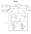
- the installation represented on the figure 1 comprises an electrical system 10, for example an information processing system with at least one computer 12.
- This information processing system 10 is intended to be supplied with direct current, at an intensity that it imposes according to its consumption at each instant and at a predetermined constant voltage.
- the information processing system 10 is a set of computer servers forming an HPC calculator. It is for example designed to be supplied with maximum continuous current of 700 A at a substantially constant voltage of 12 V.
- substantially constant is meant a DC voltage whose variations are sufficiently small around its reference value (in this case 12 V in the application in question) for the information processing system 10 to be able to support them without damage to its information processing components. Since the information processing systems, for example of calculator type, are provided with an internal conversion stage which regulates the current they consume as a function of the voltage they use to provide a very regular voltage which can go down to less than 1V, variations of 10 to 15% around the reference value of the so-called constant constant voltage supplied at the input of these systems are acceptable. Thus, for example, it is acceptable to consider that a substantially constant DC voltage of 12 V can vary between 11 and 13 V. Such a substantially constant voltage is for example obtained by a regulation of the DC voltage supplied to the processing system. information 10 using a maximum threshold voltage and a minimum threshold threshold voltage.
- the information processing system 10 is more precisely supplied with current by a DC power supply system comprising at least two DC power supply devices 14 1 and 14 2 , each comprising means of electrical connection to a source.
- AC power supply 16 1 or 16 2 and a DC AC / DC converter (not shown).
- the DC power supply system comprises a first DC power supply device 14 1 connected to a first AC power source 16 1 and a second power supply device.
- DC 14 2 connected to a second AC power source 16 2 .
- an optional but advantageous precautionary measure consists in providing that the AC power sources 16 1 and 16 2 are different.
- more than two feeding devices such as those described above could be provided.
- AC power sources 16 1 and 16 2 typically deliver a current at 50 Hz under a voltage of 230 V.
- the AC / DC converter of each device d The DC power supply converts the alternating current at 50 Hz into a voltage of 230 V into a DC current delivered at a voltage of 12 V.
- Each of the two DC power supplies 14 1 and 14 2 is chosen to have a maximum efficiency (typically 92 to 94%) when it provides 700 A at a substantially constant voltage of 12 V, ie ie when it provides what is consumed to the maximum by the information processing system 10.
- Each DC power supply device is optimized for the expected consumption of the information processing system 10 in full operating mode .
- the DC power supply system further comprises a power management module 18 of the information processing system 10.
- management module 18 is connected, for example by means of a digital data transmission bus, to the supply devices 14 1 and 14 2 and to the information processing system 10 so as to receive and transmit data information and / or control from and to these supply devices 14 1 and 14 2 and this information processing system 10.
- the data bus is not directly illustrated on the figure 1 but is functionally represented by the double arrows in bold type symbolizing the data exchanges from and to the management module 18. It can be any suitable data transmission bus in the context of the application illustrated: for example a I 2 C bus (developed by Philips), SPI (developed by Motorola), JTag (standardized by IEEE) or other.
- the management module 18 may be of a software or hardware nature and, if it is of a material nature, may comprise a dedicated hardware hardware or programmed chip. It can be integrated in the information processing system 10, in particular integrated in an HPC control server when the system 10 is an HPC computer.
- the information processing system 10 is connected to the power supply devices 14 1 and 14 2 by means of a first power supply circuit 20.
- a second branch circuit 22 of a part of the direct current supplied by one or the other of the supply devices 14 1 and 14 2 is arranged in the supply system parallel to the first circuit 20 between the devices. supply 14 1 and 14 2 and the information processing system 10.
- This second circuit 22 comprises a device 24 for backup electrical energy storage able to supply the information processing system 10 in case of failure in the circuit 20.
- the backup device 24 can draw a portion of the DC current delivered for the information processing system 10 by one or the other of the supply devices 14 1 and 14 2 in order to store data. electrical energy, and to provide, in the event of failure of an active power supply device or of the AC supply network (micro-cut-off), direct current, pulsed from the stored electrical energy, information processing system 10.
- the backup device 24 is designed to take over from the active feeder in the event of a failure.
- the emergency device 24 comprises means 26 for storing electrical energy.
- These storage means 26 may comprise one or more conventional batteries.
- Accumulator batteries generally have a good ratio of stored energy per unit volume. On the other hand, they have a bad ratio of peak power emitted per unit of volume, which makes them not very advantageous for applications where the information processing system 10 is consuming a high intensity direct current. This is particularly the case when the information processing system 10 is an HPC computer since a direct current of 700 A may be necessary.
- the means 26 for storing electrical energy advantageously comprise at least one supercapacitor, preferably at least one supercapacitor circuit arranged in series, whose peak power ratio emitted per unit volume is much higher.
- This peak power can not, however, be emitted for a too long period, but it is more than enough to overcome the micro-cuts of a good AC power supply network or the transitions between two power supply devices.
- direct current usually not exceeding a few hundred milliseconds.
- Supercapacitors are generally of the EDLC (English Electrochemical Double Layer Capacitor) type, that is to say, designed according to the electrochemical double layer method. They have a much lower internal resistance than batteries.
- the means 26 for storing electrical energy with supercapacitors can be modeled by a series RC-type circuit (ie circuit comprising a resistor and a capacitor in series), connected on the one hand to ground and on the other hand to the second circuit. 22, resistance R and capacitance C.
- the emergency device 24 further comprises means 28 for charging the means 26 for storing electrical energy from a portion of the direct current supplied by at least one of the DC supply devices 14 1 or 14 2 .
- These charging means 28 consist of a conventional supercapacitor charger and will not be detailed. They make it possible to charge the means 26 for storing electrical energy in a few minutes, in general not more than three minutes, thus disturbing the operation of the information processing system 10 rather little.
- the emergency device 24 also comprises means 30, 32 for discharging the energy stored in the means 26 for storing electrical energy to the power supply of the information processing system 10, at a given intensity. (imposed by the information processing system 10) and a predetermined substantially constant voltage, following the detection of a failure (voltage drop below an acceptable threshold) in the supply circuit 20.
- These discharge means comprise a switch 30 controlled by a controller 32.
- the switch 30 comprises for example at least one pair of N-MOS field effect transistors arranged head to tail in series. This pairwise arrangement makes it possible to isolate the supercapacitors from the means 26 for storing electrical energy from the information processing system 10, whatever the voltage across the supercapacitors and the information processing system 10. Moreover, if at the time of discharge the current to pass through the switch 30 is greater than can support such a pair of transistors, several pairs of transistors arranged in parallel, controlled by the same controller 32, may be provided to form the switch 30 .
- the switch 30 is illustrated on the figure 1 by an ideal switch which is associated with an internal resistor 34.
- the controller 32 is, in turn, designed to be able to detect a failure as soon as the value of the voltage supplied to the information processing system 10 becomes less than a predetermined threshold voltage .
- the direct current of 700 A supplied by any of the DC power supply devices 14 1 or 14 2 to the power supply of the information processing system 10 has, for example, a voltage of 12 V on the first supply circuit 20.
- the current taken by the second branch circuit 22 therefore has a priori the same voltage of 12 V.
- the means 26 for storing electrical energy can provide a direct current to the information processing system 10 at the same voltage of 12 volts, it is necessary that they are charged to a higher voltage, due in particular to the internal resistance of the means 26 for storing electrical energy and that of the switch 30. For example, this higher voltage required may be close to 15 volts.
- the switch 30 is composed of field effect MOS transistors which must feed the gate, the controller 32 must generally provide a voltage greater than 20 volts.
- a voltage booster 36 of conventional type is provided upstream of the charger 28 and the controller 32 in the second circuit 22, to raise the voltage from 12 V to 21 V for example.
- two booster seats Different voltages could be envisaged, one for the charger 28, the other for the controller 32, since the voltages they need are not the same.
- the backup device 24 therefore advantageously comprises additional means 38 for storing electrical energy, for example consisting of simple capacitors, called smoothing capacitors, arranged in parallel at the output of the switch 30.
- the additional means 38 for storing electrical energy can, as the storage means 26 supercapacitors, be modeled by a series RC type circuit, connected firstly to the ground and secondly to the second circuit 22 at the output of the switch 30, resistance r and capacitance c.
- about twenty smoothing capacitors may be arranged at the output of the switch 30, for a resistance r of 0.5 m ⁇ and a capacitance c of 0.01 F.
- the emergency device 24, with its charger 28, its controller 32, its voltage booster 36, its switch 30, and its storage means 26 and 38, is mounted on a support card and having an internal resistance equal to 40 for example at 0.1 m ⁇ .
- the second circuit 22 is also connected to the first circuit 20 so that it allows a load of the backup device 24 with the aid of this DC current of 12 V. This load is done by a DC power consumption included generally between 0.5 and 18 A.
- the second circuit 22 also allows the controller 32 to take the value of the DC voltage supplied by the first circuit 20 so as to detect a possible failure, by the appearance of a voltage drop.
- the voltage enhancer 36 for example a switching DC / DC converter, enhances the DC voltage supplied by the second circuit 22 in a direct current at 21 V intensity between 0 and 9 A depending on the device 24 rescue is in charge or not. This current supplies the controller 32 and the charger 28.
- the charger 28 in turn provides the means 26 for storing electrical energy a direct current whose intensity varies between 0 and 12 A depending on whether the device 24 is in a charging situation or not.
- the means 26 for storing electrical energy so that, in a discharge situation, they can supply a current of 700 A for, for example, at most 480 ms at a voltage of approximately 12 V always at least greater than a predetermined limit for example fixed at 11 V.
- the means 26 for storing electrical energy comprise at least one circuit of six supercapacitors arranged in series.
- the means 26 for storing electrical energy comprise at least one circuit of six supercapacitors arranged in series.
- supercapacitors whose characteristics are as follows: a capacity equal to 600 F, an internal resistance equal to 0.83 m ⁇ and a maximum potential difference supported across the supercapacitor of 2.7 V.
- V V 0 - IT / VS - RI
- I 700 A to the current delivered by the circuit
- T 480 ms the maximum discharge time
- the charging voltage V 0 must be at least 17.85 V.
- the second circuit 22 it is thus possible for the second circuit 22 to deliver a current of 700 A under a voltage substantially constant, that is to say always between 11 and 13 V, in a situation of discharge of the backup device 24, for a maximum duration of 480 ms. It will also be noted that means 26 for storing electrical energy having these equivalent resistance and capacity parameters using supercapacitors can be charged in less than three minutes by the charger 28.
- the backup device 24 described above is also connected to the management module 18 by means of the digital data transmission bus which connects the management module 18 to the other elements of the installation.
- the management module 18 is thus able to receive and transmit information and / or control data from and to the supply devices 14 1 and 14 2 , the backup device 24 and the processing system. information 10.
- the management module 18 is programmed to, after receiving a failure information of an active feeder device 14 1 or 14 2 , transmit a start command of another device power supply (14 2 or 14 1 ) inactive so as to activate the start of the idle supply device during a discharge phase of the backup device 24.
- the management module 18 optionally receives information messages from the active elements of the installation, for example the information processing system 10 and the first device DC power supply 14 1 . It also receives status information from other elements such as the second DC power supply device 14 2 inactive and the backup device 24. This status information informs, for example, the management module 18 of the availability (ie character operational) of these other elements in case of necessity.
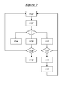
- a failure occurs in the power supply of the information processing system 10 and at least one alert is transmitted to the management module 18 from the active feeder device 14 1 , the backup device 24 when it has itself automatically detected this failure, or as a last resort of the information processing system 10.
- This failure may be due to a longer or shorter break of the source 16 1 of AC power supply or at a failure of the active feeder device 14 1 itself.
- the reduced consumption mode can be transmitted by the latter to the information processing system 10.
- This reduced consumption mode consists for example in reducing the frequency and the operating voltage of the computer 12 when the system 10 comprises at least one such computer.
- the reduced power mode may consist of operating at a frequency of 800 MHz or less with a processor core subjected to a voltage of 0.8 V or less. In this way, it is possible to immediately reduce the energy consumption of the information processing system 10 by a factor of 3 or 4.
- step 104 the management module 18 sends a stop command own information processing system 10 during the automatic discharge phase of the capacitance block "holdup" of the first DC power supply device 14 1 .
- stop stop is meant a stop following a rigorous predetermined sequence of steps to stop all processes of the information processing system 10 without risk of damaging the latter. It is assumed that this own shutdown is of duration T1 less than or equal to the duration T2 of the automatic discharge of the capacitor block "holdup".
- step 106 If the backup device 24 is available but not the second DC supply device 14 2 , in the event of a fault detected in step 102, this situation is passed to step 106 in which the device backup 24 automatically enters the discharge phase and possibly inform the management module 18. Alternatively, if the backup device 24 does not automatically enter the discharge phase, it can be caused by the management module 18 by issuing a specific order.
- the next step 108 is a waiting step, by the management module 18, of a resumption of the supply, that is to say of an end of the failure. If we note T3 the maximum duration of discharge of the backup device, that is to say the duration beyond from which it is no longer able to supply a DC current at the desired voltage to the information processing system 10, then the step 108 lasts at most T3-T1.
- step 100 If the power resumes in this step, we go to step 100 (possibly returning to the normal consumption mode of the information processing system 10 if the reduced consumption mode was activated in step 102) . Otherwise, we go to step 110 during which the management module 18 sends a clean shutdown command of the information processing system 10.
- step 112 If the second DC power supply device 14 2 and the emergency device 24 are available, in the event of a fault detected in step 102, this situation is passed to step 112 in which the emergency device 24 automatically enters the discharge phase and possibly informs the management module 18. Alternatively, if the backup device 24 does not automatically enter the discharge phase, it may be caused by the management module 18 by emission of a specific order.
- the next step 114 is a waiting step, by the management module 18, of a resumption of the supply, that is to say of an end of the failure. If we note T4 the start time of the second DC power supply device 14 2 , that is to say the time required for the latter to be able to provide a DC current at the desired voltage to the system of processing information 10 after transmission by the management module 18 of a start command, then step 114 lasts at most T3-T4.
- step 100 If the power resumes in this step, we go to step 100 (possibly returning to the normal consumption mode of the information processing system 10 if the reduced consumption mode was activated in step 102) . Otherwise, proceed to step 116 in which the management module 18 sends a start command of the second DC supply device 14 2 .
- the first DC power supply device 14 1 has not stopped by itself, because of the failure, for example, it goes to a step 118 during which the management module 18 send an order stopping the first DC power supply device 14 1 .
- the cause of the failure can then be handled by an operator.
- step 118 is followed by a return to step 100 (possibly returning to normal consumption mode of the information processing system 10 if the reduced consumption mode has been activated in step 102), with the difference that it is now the second DC power supply device 14 2 which is active and the first DC power supply device 14 1 which is inactive.
- the backup device 24 recharges to be available again in case of future failure.
Landscapes
- Engineering & Computer Science (AREA)
- Theoretical Computer Science (AREA)
- Power Engineering (AREA)
- Physics & Mathematics (AREA)
- General Engineering & Computer Science (AREA)
- General Physics & Mathematics (AREA)
- Business, Economics & Management (AREA)
- Emergency Management (AREA)
- Stand-By Power Supply Arrangements (AREA)
- Charge And Discharge Circuits For Batteries Or The Like (AREA)
Applications Claiming Priority (1)
| Application Number | Priority Date | Filing Date | Title |
|---|---|---|---|
| FR1051511A FR2957204B1 (fr) | 2010-03-02 | 2010-03-02 | Systeme et procede d'alimentation en courant continu d'un systeme electrique |
Publications (3)
| Publication Number | Publication Date |
|---|---|
| EP2363940A2 true EP2363940A2 (de) | 2011-09-07 |
| EP2363940A3 EP2363940A3 (de) | 2014-03-12 |
| EP2363940B1 EP2363940B1 (de) | 2022-01-05 |
Family
ID=43216335
Family Applications (1)
| Application Number | Title | Priority Date | Filing Date |
|---|---|---|---|
| EP11305222.9A Active EP2363940B1 (de) | 2010-03-02 | 2011-03-01 | Gleichstromversorgung eines elektrischen Systems und Verfahren dazu |
Country Status (3)
| Country | Link |
|---|---|
| US (1) | US8713332B2 (de) |
| EP (1) | EP2363940B1 (de) |
| FR (1) | FR2957204B1 (de) |
Cited By (6)
| Publication number | Priority date | Publication date | Assignee | Title |
|---|---|---|---|---|
| CN103138384A (zh) * | 2013-03-22 | 2013-06-05 | 深圳供电局有限公司 | 交流与柔性直流混合供电区域备自投配置系统及方法 |
| EP2608346A1 (de) * | 2011-12-23 | 2013-06-26 | Thales | Zufuhrsystem mit Auswahl des priorisierten Netzes |
| EP2610985A1 (de) * | 2011-12-30 | 2013-07-03 | Thales | Stromversorgungssystem mit heterogenem Mehrfacheingang |
| CN103683478A (zh) * | 2013-12-20 | 2014-03-26 | 黑龙江大学 | 单片机用锂电池式短时供电系统及供电的方法 |
| CN109863663A (zh) * | 2016-06-15 | 2019-06-07 | 卡特莱戈系统有限责任公司 | 电源充电系统 |
| US11332015B2 (en) | 2017-12-15 | 2022-05-17 | Katlego Systems, Llc | Power supply charging system |
Families Citing this family (13)
| Publication number | Priority date | Publication date | Assignee | Title |
|---|---|---|---|---|
| US20100332857A1 (en) | 2009-06-30 | 2010-12-30 | Vogman Viktor D | Reducing power losses in a redundant power supply system |
| CN103023128B (zh) | 2011-09-27 | 2016-06-15 | 台达电子企业管理(上海)有限公司 | 一种用于ups服务器的电源系统 |
| JP5962101B2 (ja) * | 2012-03-19 | 2016-08-03 | 富士通株式会社 | バックアップ電源装置、電源システム、コンピュータシステム、コンピュータシステムの電源制御方法および電源制御プログラム |
| CN103368250B (zh) * | 2012-03-27 | 2016-04-13 | 中航太克(厦门)电子有限公司 | 一种大电流切换控制装置 |
| DE102012207379A1 (de) * | 2012-05-03 | 2013-11-07 | Robert Bosch Gmbh | Vorrichtung und Verfahren zur Versorgung eines elektrischen Antriebes mit elektrischem Strom |
| US9660540B2 (en) | 2012-11-05 | 2017-05-23 | Flextronics Ap, Llc | Digital error signal comparator |
| US9494658B2 (en) * | 2013-03-14 | 2016-11-15 | Flextronics Ap, Llc | Approach for generation of power failure warning signal to maximize useable hold-up time with AC/DC rectifiers |
| US9627915B2 (en) | 2013-03-15 | 2017-04-18 | Flextronics Ap, Llc | Sweep frequency mode for multiple magnetic resonant power transmission |
| CN103365390A (zh) * | 2013-07-11 | 2013-10-23 | 浪潮电子信息产业股份有限公司 | 一种机柜的供电方法 |
| JP6163121B2 (ja) * | 2014-02-26 | 2017-07-12 | サンケン電気株式会社 | 自立運転システム |
| US9621053B1 (en) | 2014-08-05 | 2017-04-11 | Flextronics Ap, Llc | Peak power control technique for primary side controller operation in continuous conduction mode |
| US9515560B1 (en) | 2014-08-08 | 2016-12-06 | Flextronics Ap, Llc | Current controlled resonant tank circuit |
| CN107210621A (zh) * | 2015-01-23 | 2017-09-26 | 西门子股份公司 | 船舶上的电能的分配 |
Citations (3)
| Publication number | Priority date | Publication date | Assignee | Title |
|---|---|---|---|---|
| EP0402833A2 (de) | 1989-06-12 | 1990-12-19 | Siemens Aktiengesellschaft | Schaltung zum Überwachen der Spannung einer ausgewählten Gleichstromversorgungseinrichtung in einem redundanten Stromversorgungssystem |
| US20010022472A1 (en) | 1999-09-30 | 2001-09-20 | George Codina | Method and apparatus for providing uninterrupted power during transitions between a power source and a standby generator using capacitor supplied voltage |
| US20070152506A1 (en) | 2006-01-05 | 2007-07-05 | Sprint Communications Company L.P. | Telecommunications megasite with backup power system |
Family Cites Families (13)
| Publication number | Priority date | Publication date | Assignee | Title |
|---|---|---|---|---|
| US4673826A (en) | 1984-12-20 | 1987-06-16 | The United States Of America As Represented By The Secretary Of The Air Force | Autonomous uninterruptable power supply apparatus |
| DE3704426A1 (de) * | 1986-05-05 | 1987-11-12 | Siemens Ag | Einrichtung zur redundanten gleichstromspeisung elektrischer verbraucher |
| US5184025A (en) * | 1988-11-14 | 1993-02-02 | Elegant Design Solutions, Inc. | Computer-controlled uninterruptible power supply |
| US5612580A (en) | 1995-10-10 | 1997-03-18 | Northrop Grumman Corporation | Uninterruptible power system |
| US5894413A (en) * | 1997-01-28 | 1999-04-13 | Sony Corporation | Redundant power supply switchover circuit |
| US5939799A (en) * | 1997-07-16 | 1999-08-17 | Storage Technology Corporation | Uninterruptible power supply with an automatic transfer switch |
| WO2003032429A2 (en) * | 2001-10-12 | 2003-04-17 | Proton Energy Systems, Inc. | Method and system for bridging short duration power interruptions |
| DE10244608B4 (de) * | 2002-09-25 | 2008-01-24 | Siemens Ag | Stromversorgungsanlage mit Ladeschutzeinrichtung für eine Notstrom-Batterie |
| US7573232B2 (en) | 2003-08-08 | 2009-08-11 | American Power Conversion Corporation | Battery exchange apparatus and method for uninterruptible power supply |
| US20050036253A1 (en) | 2003-08-13 | 2005-02-17 | Shou-Long Tian | Modular AC power supply system with fault bypass and method of switching output modes |
| US20060192433A1 (en) * | 2005-02-28 | 2006-08-31 | Fuglevand William A | Uninterruptible power supply and method for supplying uninterruptible power to a load |
| JP4793920B2 (ja) * | 2006-02-24 | 2011-10-12 | 株式会社リコー | 電源装置および画像形成装置 |
| US8729732B2 (en) * | 2008-07-10 | 2014-05-20 | T-Mobile Usa, Inc. | Cell site power generation |
-
2010
- 2010-03-02 FR FR1051511A patent/FR2957204B1/fr active Active
-
2011
- 2011-03-01 EP EP11305222.9A patent/EP2363940B1/de active Active
- 2011-03-02 US US13/038,404 patent/US8713332B2/en active Active
Patent Citations (3)
| Publication number | Priority date | Publication date | Assignee | Title |
|---|---|---|---|---|
| EP0402833A2 (de) | 1989-06-12 | 1990-12-19 | Siemens Aktiengesellschaft | Schaltung zum Überwachen der Spannung einer ausgewählten Gleichstromversorgungseinrichtung in einem redundanten Stromversorgungssystem |
| US20010022472A1 (en) | 1999-09-30 | 2001-09-20 | George Codina | Method and apparatus for providing uninterrupted power during transitions between a power source and a standby generator using capacitor supplied voltage |
| US20070152506A1 (en) | 2006-01-05 | 2007-07-05 | Sprint Communications Company L.P. | Telecommunications megasite with backup power system |
Cited By (16)
| Publication number | Priority date | Publication date | Assignee | Title |
|---|---|---|---|---|
| EP2608346A1 (de) * | 2011-12-23 | 2013-06-26 | Thales | Zufuhrsystem mit Auswahl des priorisierten Netzes |
| FR2985103A1 (fr) * | 2011-12-23 | 2013-06-28 | Thales Sa | Systeme d'alimentation a selection de reseau priorise. |
| US9099869B2 (en) | 2011-12-23 | 2015-08-04 | Thales | Power supply system with prioritized network selection |
| EP2610985A1 (de) * | 2011-12-30 | 2013-07-03 | Thales | Stromversorgungssystem mit heterogenem Mehrfacheingang |
| FR2985392A1 (fr) * | 2011-12-30 | 2013-07-05 | Thales Sa | Systeme d'alimentation electrique a entree multiple heterogene |
| US9469411B2 (en) | 2011-12-30 | 2016-10-18 | Thales | Power supply system with heterogeneous multiple input |
| CN103138384A (zh) * | 2013-03-22 | 2013-06-05 | 深圳供电局有限公司 | 交流与柔性直流混合供电区域备自投配置系统及方法 |
| CN103138384B (zh) * | 2013-03-22 | 2014-11-26 | 深圳供电局有限公司 | 交流与柔性直流混合供电区域备自投配置系统及方法 |
| CN103683478B (zh) * | 2013-12-20 | 2015-08-19 | 黑龙江大学 | 单片机用锂电池式短时供电系统及供电的方法 |
| CN103683478A (zh) * | 2013-12-20 | 2014-03-26 | 黑龙江大学 | 单片机用锂电池式短时供电系统及供电的方法 |
| CN109863663A (zh) * | 2016-06-15 | 2019-06-07 | 卡特莱戈系统有限责任公司 | 电源充电系统 |
| US10581252B2 (en) | 2016-06-15 | 2020-03-03 | Katlego Systems, Llc | Power supply charging system |
| CN109863663B (zh) * | 2016-06-15 | 2021-07-20 | 卡特莱戈系统有限责任公司 | 电源充电系统 |
| US11101666B2 (en) | 2016-06-15 | 2021-08-24 | Katlego Systems, Llc | Power supply charging system |
| US11332015B2 (en) | 2017-12-15 | 2022-05-17 | Katlego Systems, Llc | Power supply charging system |
| US11724599B2 (en) | 2017-12-15 | 2023-08-15 | Katlego Systems, Llc | Power supply charging system |
Also Published As
| Publication number | Publication date |
|---|---|
| FR2957204B1 (fr) | 2014-11-21 |
| EP2363940A3 (de) | 2014-03-12 |
| EP2363940B1 (de) | 2022-01-05 |
| US20110213999A1 (en) | 2011-09-01 |
| US8713332B2 (en) | 2014-04-29 |
| FR2957204A1 (fr) | 2011-09-09 |
Similar Documents
| Publication | Publication Date | Title |
|---|---|---|
| EP2363940B1 (de) | Gleichstromversorgung eines elektrischen Systems und Verfahren dazu | |
| EP2351188B1 (de) | Ununterbrechbare gleichstrom-stromversorgungseinrichtung für ein datenverarbeitungssystem mit mindestens einem prozessor | |
| EP2363939B1 (de) | Unterbrechungsfreie Wechselstromversorgung einer Installation und Verfahren dazu | |
| EP2783443B1 (de) | Gesichertes und geregeltes kontinuierliches stromversorgungssystem mit mehreren eingängen | |
| EP0578531B1 (de) | Unterbrechnungsfreie Stromversorgung mit verteiltem Speichersystem | |
| WO2011138381A2 (fr) | Systeme d'equilibrage pour batterie de puissance et procede d'equilibrage de charge correspondant | |
| CA2692300C (fr) | Procede et systeme de gestion de coupures d'alimentation electrique a bord d'un aeronef | |
| FR2910141A1 (fr) | Systeme de generation d'energie electrique avec maximisation de la puissance | |
| FR2908939A1 (fr) | Dispositif de commande pour assurer la regulation en tension d'un bus d'alimentation. | |
| WO2011003975A1 (fr) | Nouvelle architecture de compensateur des facteurs de puissance et d'harmoniques pour reseau de distribution d'energie | |
| EP2961029A1 (de) | Ausgleichsmodul für kurze netzunterbrechungen der stromzufuhr zu einem server | |
| EP2395594B1 (de) | Vorrichtung und Verfahren zur Stromversorgung eines mobilen Kommunikationssystems und eine Sensoranordnung, die eine derartige Vorrichtung aufweist. | |
| EP2079147A1 (de) | Elektrischer Schaltkreis | |
| EP0970556B1 (de) | Preiswerte versorgungseinrichtung einer mehrzahl von elektronischen submodulen in einem baugruppenträger | |
| WO2006117488A2 (fr) | Circuit d'alimentation sans interruption | |
| EP3185389B1 (de) | Vorrichtung und elektrisches gerät zur erzeugung einer elektrischen spannung für eine informationsbearbeitungseinheit, und entsprechendes elektronisches system zur informationsbearbeitung | |
| FR3045973A1 (fr) | Dispositif de distribution redondante d'alimentation sans interruption et procede de commande associe | |
| FR2936221A1 (fr) | Systeme et procede de distribution electrique a bord d'un aeronef | |
| EP1432096A2 (de) | Konstantspannung-Ladungszustandsteuervorrichtung für eine Einheit mit sekundären elektrochemischen Generatoren | |
| EP0284479B1 (de) | Verfahren und Notstromversorgung, um ein ausfallendes Stromnetz zu ersetzen | |
| FR2965423A1 (fr) | Dispositif d'optimisation de la gestion d'energie pour reseau de bord de vehicule comprenant un ou une pluralite de dispositifs de maintien de tension | |
| FR2777396A1 (fr) | Dispositif et procede d'alimentation electrique securisee pour systeme de reproduction audiovisuelle | |
| WO1991018339A1 (fr) | Dispositif de protection externe de systemes informatiques a l'egard des microcoupures de l'alimentation electrique |
Legal Events
| Date | Code | Title | Description |
|---|---|---|---|
| PUAI | Public reference made under article 153(3) epc to a published international application that has entered the european phase |
Free format text: ORIGINAL CODE: 0009012 |
|
| AK | Designated contracting states |
Kind code of ref document: A2 Designated state(s): AL AT BE BG CH CY CZ DE DK EE ES FI FR GB GR HR HU IE IS IT LI LT LU LV MC MK MT NL NO PL PT RO RS SE SI SK SM TR |
|
| AX | Request for extension of the european patent |
Extension state: BA ME |
|
| PUAL | Search report despatched |
Free format text: ORIGINAL CODE: 0009013 |
|
| AK | Designated contracting states |
Kind code of ref document: A3 Designated state(s): AL AT BE BG CH CY CZ DE DK EE ES FI FR GB GR HR HU IE IS IT LI LT LU LV MC MK MT NL NO PL PT RO RS SE SI SK SM TR |
|
| AX | Request for extension of the european patent |
Extension state: BA ME |
|
| RIC1 | Information provided on ipc code assigned before grant |
Ipc: H02J 1/10 20060101ALI20140206BHEP Ipc: G06F 1/26 20060101ALI20140206BHEP Ipc: H02J 9/06 20060101AFI20140206BHEP Ipc: G06F 1/30 20060101ALI20140206BHEP |
|
| STAA | Information on the status of an ep patent application or granted ep patent |
Free format text: STATUS: REQUEST FOR EXAMINATION WAS MADE |
|
| 17P | Request for examination filed |
Effective date: 20140911 |
|
| RBV | Designated contracting states (corrected) |
Designated state(s): AL AT BE BG CH CY CZ DE DK EE ES FI FR GB GR HR HU IE IS IT LI LT LU LV MC MK MT NL NO PL PT RO RS SE SI SK SM TR |
|
| STAA | Information on the status of an ep patent application or granted ep patent |
Free format text: STATUS: EXAMINATION IS IN PROGRESS |
|
| 17Q | First examination report despatched |
Effective date: 20210223 |
|
| GRAP | Despatch of communication of intention to grant a patent |
Free format text: ORIGINAL CODE: EPIDOSNIGR1 |
|
| STAA | Information on the status of an ep patent application or granted ep patent |
Free format text: STATUS: GRANT OF PATENT IS INTENDED |
|
| INTG | Intention to grant announced |
Effective date: 20210517 |
|
| GRAJ | Information related to disapproval of communication of intention to grant by the applicant or resumption of examination proceedings by the epo deleted |
Free format text: ORIGINAL CODE: EPIDOSDIGR1 |
|
| STAA | Information on the status of an ep patent application or granted ep patent |
Free format text: STATUS: EXAMINATION IS IN PROGRESS |
|
| INTC | Intention to grant announced (deleted) | ||
| GRAP | Despatch of communication of intention to grant a patent |
Free format text: ORIGINAL CODE: EPIDOSNIGR1 |
|
| STAA | Information on the status of an ep patent application or granted ep patent |
Free format text: STATUS: GRANT OF PATENT IS INTENDED |
|
| GRAS | Grant fee paid |
Free format text: ORIGINAL CODE: EPIDOSNIGR3 |
|
| INTG | Intention to grant announced |
Effective date: 20211103 |
|
| GRAA | (expected) grant |
Free format text: ORIGINAL CODE: 0009210 |
|
| STAA | Information on the status of an ep patent application or granted ep patent |
Free format text: STATUS: THE PATENT HAS BEEN GRANTED |
|
| AK | Designated contracting states |
Kind code of ref document: B1 Designated state(s): AL AT BE BG CH CY CZ DE DK EE ES FI FR GB GR HR HU IE IS IT LI LT LU LV MC MK MT NL NO PL PT RO RS SE SI SK SM TR |
|
| REG | Reference to a national code |
Ref country code: GB Ref legal event code: FG4D Free format text: NOT ENGLISH |
|
| REG | Reference to a national code |
Ref country code: CH Ref legal event code: EP |
|
| REG | Reference to a national code |
Ref country code: AT Ref legal event code: REF Ref document number: 1461451 Country of ref document: AT Kind code of ref document: T Effective date: 20220115 |
|
| REG | Reference to a national code |
Ref country code: DE Ref legal event code: R096 Ref document number: 602011072351 Country of ref document: DE |
|
| REG | Reference to a national code |
Ref country code: IE Ref legal event code: FG4D Free format text: LANGUAGE OF EP DOCUMENT: FRENCH |
|
| REG | Reference to a national code |
Ref country code: LT Ref legal event code: MG9D |
|
| REG | Reference to a national code |
Ref country code: NL Ref legal event code: MP Effective date: 20220105 |
|
| REG | Reference to a national code |
Ref country code: AT Ref legal event code: MK05 Ref document number: 1461451 Country of ref document: AT Kind code of ref document: T Effective date: 20220105 |
|
| PG25 | Lapsed in a contracting state [announced via postgrant information from national office to epo] |
Ref country code: NL Free format text: LAPSE BECAUSE OF FAILURE TO SUBMIT A TRANSLATION OF THE DESCRIPTION OR TO PAY THE FEE WITHIN THE PRESCRIBED TIME-LIMIT Effective date: 20220105 |
|
| PG25 | Lapsed in a contracting state [announced via postgrant information from national office to epo] |
Ref country code: SE Free format text: LAPSE BECAUSE OF FAILURE TO SUBMIT A TRANSLATION OF THE DESCRIPTION OR TO PAY THE FEE WITHIN THE PRESCRIBED TIME-LIMIT Effective date: 20220105 Ref country code: RS Free format text: LAPSE BECAUSE OF FAILURE TO SUBMIT A TRANSLATION OF THE DESCRIPTION OR TO PAY THE FEE WITHIN THE PRESCRIBED TIME-LIMIT Effective date: 20220105 Ref country code: PT Free format text: LAPSE BECAUSE OF FAILURE TO SUBMIT A TRANSLATION OF THE DESCRIPTION OR TO PAY THE FEE WITHIN THE PRESCRIBED TIME-LIMIT Effective date: 20220505 Ref country code: NO Free format text: LAPSE BECAUSE OF FAILURE TO SUBMIT A TRANSLATION OF THE DESCRIPTION OR TO PAY THE FEE WITHIN THE PRESCRIBED TIME-LIMIT Effective date: 20220405 Ref country code: LT Free format text: LAPSE BECAUSE OF FAILURE TO SUBMIT A TRANSLATION OF THE DESCRIPTION OR TO PAY THE FEE WITHIN THE PRESCRIBED TIME-LIMIT Effective date: 20220105 Ref country code: HR Free format text: LAPSE BECAUSE OF FAILURE TO SUBMIT A TRANSLATION OF THE DESCRIPTION OR TO PAY THE FEE WITHIN THE PRESCRIBED TIME-LIMIT Effective date: 20220105 Ref country code: ES Free format text: LAPSE BECAUSE OF FAILURE TO SUBMIT A TRANSLATION OF THE DESCRIPTION OR TO PAY THE FEE WITHIN THE PRESCRIBED TIME-LIMIT Effective date: 20220105 Ref country code: BG Free format text: LAPSE BECAUSE OF FAILURE TO SUBMIT A TRANSLATION OF THE DESCRIPTION OR TO PAY THE FEE WITHIN THE PRESCRIBED TIME-LIMIT Effective date: 20220405 |
|
| PG25 | Lapsed in a contracting state [announced via postgrant information from national office to epo] |
Ref country code: PL Free format text: LAPSE BECAUSE OF FAILURE TO SUBMIT A TRANSLATION OF THE DESCRIPTION OR TO PAY THE FEE WITHIN THE PRESCRIBED TIME-LIMIT Effective date: 20220105 Ref country code: LV Free format text: LAPSE BECAUSE OF FAILURE TO SUBMIT A TRANSLATION OF THE DESCRIPTION OR TO PAY THE FEE WITHIN THE PRESCRIBED TIME-LIMIT Effective date: 20220105 Ref country code: GR Free format text: LAPSE BECAUSE OF FAILURE TO SUBMIT A TRANSLATION OF THE DESCRIPTION OR TO PAY THE FEE WITHIN THE PRESCRIBED TIME-LIMIT Effective date: 20220406 Ref country code: FI Free format text: LAPSE BECAUSE OF FAILURE TO SUBMIT A TRANSLATION OF THE DESCRIPTION OR TO PAY THE FEE WITHIN THE PRESCRIBED TIME-LIMIT Effective date: 20220105 Ref country code: AT Free format text: LAPSE BECAUSE OF FAILURE TO SUBMIT A TRANSLATION OF THE DESCRIPTION OR TO PAY THE FEE WITHIN THE PRESCRIBED TIME-LIMIT Effective date: 20220105 |
|
| PG25 | Lapsed in a contracting state [announced via postgrant information from national office to epo] |
Ref country code: IS Free format text: LAPSE BECAUSE OF FAILURE TO SUBMIT A TRANSLATION OF THE DESCRIPTION OR TO PAY THE FEE WITHIN THE PRESCRIBED TIME-LIMIT Effective date: 20220505 |
|
| REG | Reference to a national code |
Ref country code: DE Ref legal event code: R097 Ref document number: 602011072351 Country of ref document: DE |
|
| PG25 | Lapsed in a contracting state [announced via postgrant information from national office to epo] |
Ref country code: SM Free format text: LAPSE BECAUSE OF FAILURE TO SUBMIT A TRANSLATION OF THE DESCRIPTION OR TO PAY THE FEE WITHIN THE PRESCRIBED TIME-LIMIT Effective date: 20220105 Ref country code: SK Free format text: LAPSE BECAUSE OF FAILURE TO SUBMIT A TRANSLATION OF THE DESCRIPTION OR TO PAY THE FEE WITHIN THE PRESCRIBED TIME-LIMIT Effective date: 20220105 Ref country code: RO Free format text: LAPSE BECAUSE OF FAILURE TO SUBMIT A TRANSLATION OF THE DESCRIPTION OR TO PAY THE FEE WITHIN THE PRESCRIBED TIME-LIMIT Effective date: 20220105 Ref country code: MC Free format text: LAPSE BECAUSE OF FAILURE TO SUBMIT A TRANSLATION OF THE DESCRIPTION OR TO PAY THE FEE WITHIN THE PRESCRIBED TIME-LIMIT Effective date: 20220105 Ref country code: EE Free format text: LAPSE BECAUSE OF FAILURE TO SUBMIT A TRANSLATION OF THE DESCRIPTION OR TO PAY THE FEE WITHIN THE PRESCRIBED TIME-LIMIT Effective date: 20220105 Ref country code: DK Free format text: LAPSE BECAUSE OF FAILURE TO SUBMIT A TRANSLATION OF THE DESCRIPTION OR TO PAY THE FEE WITHIN THE PRESCRIBED TIME-LIMIT Effective date: 20220105 Ref country code: CZ Free format text: LAPSE BECAUSE OF FAILURE TO SUBMIT A TRANSLATION OF THE DESCRIPTION OR TO PAY THE FEE WITHIN THE PRESCRIBED TIME-LIMIT Effective date: 20220105 |
|
| REG | Reference to a national code |
Ref country code: CH Ref legal event code: PL |
|
| PLBE | No opposition filed within time limit |
Free format text: ORIGINAL CODE: 0009261 |
|
| STAA | Information on the status of an ep patent application or granted ep patent |
Free format text: STATUS: NO OPPOSITION FILED WITHIN TIME LIMIT |
|
| PG25 | Lapsed in a contracting state [announced via postgrant information from national office to epo] |
Ref country code: AL Free format text: LAPSE BECAUSE OF FAILURE TO SUBMIT A TRANSLATION OF THE DESCRIPTION OR TO PAY THE FEE WITHIN THE PRESCRIBED TIME-LIMIT Effective date: 20220105 |
|
| REG | Reference to a national code |
Ref country code: BE Ref legal event code: MM Effective date: 20220331 |
|
| 26N | No opposition filed |
Effective date: 20221006 |
|
| PG25 | Lapsed in a contracting state [announced via postgrant information from national office to epo] |
Ref country code: LU Free format text: LAPSE BECAUSE OF NON-PAYMENT OF DUE FEES Effective date: 20220301 Ref country code: LI Free format text: LAPSE BECAUSE OF NON-PAYMENT OF DUE FEES Effective date: 20220331 Ref country code: IE Free format text: LAPSE BECAUSE OF NON-PAYMENT OF DUE FEES Effective date: 20220301 Ref country code: CH Free format text: LAPSE BECAUSE OF NON-PAYMENT OF DUE FEES Effective date: 20220331 |
|
| REG | Reference to a national code |
Ref country code: GB Ref legal event code: 732E Free format text: REGISTERED BETWEEN 20230105 AND 20230111 |
|
| PG25 | Lapsed in a contracting state [announced via postgrant information from national office to epo] |
Ref country code: SI Free format text: LAPSE BECAUSE OF FAILURE TO SUBMIT A TRANSLATION OF THE DESCRIPTION OR TO PAY THE FEE WITHIN THE PRESCRIBED TIME-LIMIT Effective date: 20220105 Ref country code: BE Free format text: LAPSE BECAUSE OF NON-PAYMENT OF DUE FEES Effective date: 20220331 |
|
| REG | Reference to a national code |
Ref country code: DE Ref legal event code: R081 Ref document number: 602011072351 Country of ref document: DE Owner name: COMMISSARIAT A L'ENERGIE ATOMIQUE ET AUX ENERG, FR Free format text: FORMER OWNER: BULL S.A.S., LES CLAYES SOUS BOIS, FR Ref country code: DE Ref legal event code: R081 Ref document number: 602011072351 Country of ref document: DE Owner name: BULL SAS, FR Free format text: FORMER OWNER: BULL S.A.S., LES CLAYES SOUS BOIS, FR |
|
| PGFP | Annual fee paid to national office [announced via postgrant information from national office to epo] |
Ref country code: FR Payment date: 20230320 Year of fee payment: 13 |
|
| P01 | Opt-out of the competence of the unified patent court (upc) registered |
Effective date: 20230330 |
|
| PG25 | Lapsed in a contracting state [announced via postgrant information from national office to epo] |
Ref country code: IT Free format text: LAPSE BECAUSE OF FAILURE TO SUBMIT A TRANSLATION OF THE DESCRIPTION OR TO PAY THE FEE WITHIN THE PRESCRIBED TIME-LIMIT Effective date: 20220105 |
|
| PG25 | Lapsed in a contracting state [announced via postgrant information from national office to epo] |
Ref country code: HU Free format text: LAPSE BECAUSE OF FAILURE TO SUBMIT A TRANSLATION OF THE DESCRIPTION OR TO PAY THE FEE WITHIN THE PRESCRIBED TIME-LIMIT; INVALID AB INITIO Effective date: 20110301 |
|
| PG25 | Lapsed in a contracting state [announced via postgrant information from national office to epo] |
Ref country code: MK Free format text: LAPSE BECAUSE OF FAILURE TO SUBMIT A TRANSLATION OF THE DESCRIPTION OR TO PAY THE FEE WITHIN THE PRESCRIBED TIME-LIMIT Effective date: 20220105 Ref country code: CY Free format text: LAPSE BECAUSE OF FAILURE TO SUBMIT A TRANSLATION OF THE DESCRIPTION OR TO PAY THE FEE WITHIN THE PRESCRIBED TIME-LIMIT Effective date: 20220105 |
|
| PGFP | Annual fee paid to national office [announced via postgrant information from national office to epo] |
Ref country code: DE Payment date: 20240321 Year of fee payment: 14 Ref country code: GB Payment date: 20240322 Year of fee payment: 14 |